Article

Utilization of Window System as Exhaust Air Heat Recovery Device and Its Energy Performance Evaluation: A Comparative Study

1
Institute for Design Innovation, Loughborough University, Loughborough LE11 3TU, UK
2
Department of Building Environment and Energy Engineering, The Hong Kong Polytechnic University, Hong Kong 999077, China
*
Author to whom correspondence should be addressed.
Energies 2022, 15(9), 3116; https://doi.org/10.3390/en15093116
Submission received: 30 March 2022 / Revised: 21 April 2022 / Accepted: 22 April 2022 / Published: 24 April 2022
(This article belongs to the Section G: Energy and Buildings)

Abstract

:
The exhaust air glass unit (EAGU) can be treated as an integration of multilayer glazing unit and heat recovery device to utilize the exhaust air from conditioned space with a fresh air ventilation system to improve the thermal performance of window system. However, compared with the conventionally used mechanical ventilation with a heat recovery (MVHR) system, whether the use of EAGU is energy-efficient or not has not been estimated. In this paper, a numerical model, validated by experimental measurement, was used to calculate the hourly cooling and heating loads and annual energy demand of EAGU. This study compared the annual energy performance of EAGU and MVHR under various conditions, and further discusses the applicability of EAGU for different climates. The results indicate that the energy saving potential of EAGU ranges from 26.8% to 38.2% for different climate conditions. In the cooling season, the energy saving potential of EAGU performed much better than that of the commonly used MVHR. However, the EAGU was inferior to the MVHR in the heating season. Moreover, the EAGU is more suitable for application in warm climates, rather than cold climates. This study can provide some application guidelines about the selection of exhaust air heat recovery devices for maximizing the energy saving potential.

1. Introduction

The building sector has been recognized as a major driver for reducing the energy use and carbon emission [1]. It is estimated that 40% of the global total energy use results from the building sector [2]. This fact highlights the significance and necessity of investigating various building energy-saving technologies such as a high-performance building envelope [3], data-driven building energy management [4], novel energy-efficient system [5], building integrated with renewable energy sources [6], etc. Glazing systems are responsible for approximately 60% of the total energy loss of buildings [7] and can be used to passively offer natural lighting and solar heat gain in winter. Therefore, advanced glazing technologies have the potential to achieve building energy efficiency while maintaining a comfortable indoor visual/thermal environment.
Energy-efficient glazing systems are supposed to be well insulated and able to control the solar radiation. Over the past few decades, glazing systems have been widely investigated in terms of increasing the thermal insulation or controlling the solar heat gain. Typically, applying multilayer-glazing units [8] or low-emissivity coating at the glazing surface [9] may be the most common methods to decrease the U-value of the glazing system. Highly thermal insulation glazing technologies such as the gas-filled glazing [10], aerogel glazing [11], and vacuum glazing [12] have been extensively investigated to achieve very low U-value, and then reduce the cooling and heating loads. In order to respond to the various weather conditions, smart windows [13] can modulate the optical properties of glazing to dynamically control the solar heat gain through the window. These window technologies can reduce the unwanted solar heat gain in summer and utilize the solar energy to supplement heating in winter. Technologies are also developed to apply the phase change materials into glazing unit [14,15], which can absorb and release energy to moderate the diurnal temperature fluctuation of the interior surface of a window.
In recent years, integrating renewable energy systems into buildings has received considerable attention [16]. Technologies have also been extensively developed to integrate glazing systems with low-grade energy sources such as evaporative cooling water, geothermal energy, solar heat, exhaust air from conditioned space with fresh air ventilation system, and the favorable natural air. The pipe-embedded glazing system can utilize the evaporative cooling water in summer [17,18] or the ground-source water in winter [19] to remove the heat gain or reduce heat loss through the window. Integrating the semi-transparent photovoltaic (PV) thin-film into the window can provide an approach to achieve the cooling load reduction as well as the in-site electricity generation [20]. The supply-air glazing unit (SAGU) [21], developed for application in the heating season, allows the outdoor air to flow into the indoor space through the cavity between the glazing unit, and then the cold ventilation airflow is preheated by the solar heat absorbed by glazing and the conductive heat loss through the window. The water flow window [22] allows the cold/warm water stream flowing through the channel within the glass panes to prevent the heat gain/loss of the window. The solar energy and geothermal energy are used to heat and cool the circulation water stream, respectively. Mechanical or natural ventilated double skin facade (VDSF) [23,24,25] can utilize the favorable ambient air to remove the accumulated solar heat and avoid the risk of overheating the built-in shading device in the cooling season. The energy saving potential of the VDSF can be further improved by integrating the VDSF with the earth-to-air heat exchanger [26]. The above-mentioned studies fully demonstrated that utilizing the low-grade energy sources can improve the thermal and energy performance of the glazing systems.
In addition, there exists an energy-efficient glazing unit, which can be treated as an integration of a multilayer glazing unit and exhaust air heat recovery device [27]. Such a glazing system is called the exhaust air glass unit (EAGU), as shown in Figure 1. For a conditioned-space with a fresh air ventilation system, the fresh air ventilation rate for an indoor space is approximatively equal to the exhaust air rate based on mass conservation. Moreover, temperature of this exhaust air roughly equals the indoor air temperature. This window system allows the exhaust air from the conditioned space with a fresh air ventilation system to flow through the gap within the glazing system, and utilize the low-grade exhaust air to decrease the conduction heat gain in summer and heat loss in winter. Numerous studies have demonstrated that the EAGU can enhance the building energy-efficiency, reduce the energy consumption, and guarantee the indoor thermal environment.
So far, the related studies about the EAGU have mainly focused on developing the heat transfer model, evaluating the thermal/energy performance, estimating its design parameters, proposing new structures, and integration with green energy sources. Currently, the zonal model has been validated and proven to be a sufficiently reliable method to analyze the two-dimensional heat transfer processes within the EAGU [28,29,30]. Zhang et al. [27] proposed a zonal model to investigate the thermal performance of EAGU in a hot summer and cold winter climate region. The results indicate that compared to the conventional double and triple glazing unit, the EAGU can decrease 74% and 46.8% of the heat loss in the heating season and 73.5% and 71.9% of the heat gain in the cooling season, respectively. Skaff and Gosselin [31] compared the U-factor of EAGU with that of a double glazing unit based on NFRC standards. Compared with the double glazing unit, the EAGU reduced the U-factor from 3.1 W/(m2K) to 1.9 W/(m2K) with a percentage reduction of 38.7%. Chow et al.’s [32] experiments investigated the total heat gain of the EAGU, single absorptive glazing, and double absorptive glazing unit in a subtropical climate. The EAGU reduced 61.1% and 38.6% of the total heat gain compared to the single and double absorptive glazing unit, respectively. The thermal performance of the EAGU depends on various parameters such as the glazing system component, exhaust air rate, physical properties of the glass, cavity size, and weather conditions. Kim et al. [33], Ismail and Henriquez [34], and Zhang et al. [35] conducted a series of parametric studies to optimize the window design under various design parameters and weather conditions. Further enhancement of heat recovery efficiency could be achieved by adopting a U-shaped air channel to enlarge the heat exchange area between the glazing unit and exhaust air [33]. Moreover, the feasibility of using the EAGU in evaporatively-cooled buildings was also investigated by Khalvati and Omidvar [36]. All these studies demonstrate that the EAGU provides an alternative approach to utilize the low-grade energy of exhaust air from the conditioned space with a fresh air ventilation system.
However, to reduce the energy demand of cooling/heating the ventilation fresh air, mechanical ventilation with heat recovery (MVHR) systems are widely used to achieve sensible and latent heat exchange between exhaust air and fresh air in the residential, industrial, and commercial buildings [37,38,39]. This means that the practical application of the EAGU will increase the energy demand for cooling/heating the ventilation fresh air compared with the use of the MVHR. Though many studies have showed that the EAGU can utilize the exhaust air to significantly decrease the heating and cooling load of the window, the influence of using the EAGU on the energy performance of ventilation has not been considered yet. Considering the overall energy performance of the window and ventilation system, so far, whether the use of the EAGU is energy-efficient or not has not been estimated. Therefore, it is necessary to identify the overall energy saving potential and applicability of the EAGU compared to the commonly used MVHR systems, which can provide important guidelines for the practical application of this energy efficient window.
The main objective of this research was to compare the energy performance of the EAGU and MVHR under various conditions (e.g., ventilation fresh air rate, outdoor weather condition, etc.), identify whether the use of EAGU is energy-efficient or not compared with the use of conventional MVHRs, and further discuss the feasibility of its practical application in different climates. In this paper, the year-round energy performance of the EAGU was investigated in three different climate regions and compared with that of the conventional total heat recovery ventilator (THRV) and sensible heat recovery ventilator (SHRV). Moreover, the influence of the ventilation fresh air rate on the heat recovery performance of the EAGU was also estimated. From the view point of exhaust air heat recovery, some guidelines are discussed and recommended for the practical application of EAGU.

2. Methodology

2.1. Framework of Heat Recovery Assessment

MVHR systems are commonly used to reduce the energy consumption for conditioning the ventilation fresh air, while the EAGU can recover and utilize the heat/cool of exhaust air to reduce the energy demand due to the window system. As above-mentioned, the use of EAGU increases the energy demand for conditioning the ventilation air compared with the use of MVHR.
In this study, the heat recovery potential and energy saving performance of the EAGU was assessed and compared with that of the SHRV and THRV. Case studies were carried out to compare the overall energy consumption of a typical office room employed with the EAGU, SHRV, THRV, and without any heat recovery unit. Detailed information of the case studies are presented in Table 1. For case 1, no heat recovery ventilator was adopted and all of the exhaust air flows through the EAGU to reduce the heat loss/gain of the window system. For cases 2 and 3, when employing heat recovery ventilators, the double glazed unit was adopted as the window system because it is one of the most commonly used window configurations in both commercial and residential buildings. Case 4 did not have a heat recovery unit and was used as the baseline for purposes of comparison.
Therefore, the year-round overall energy consumption of the window and ventilation system for the above-mentioned four cases were calculated and compared to identify whether the use of an EAGU is energy-efficient or not compared with the use of conventional SHRV and THRV. In this study, the simulation process involves two parts: (1) developing a numerical model of EAGU to calculate its hourly cooling/heating load and year-round total energy consumption; and (2) calculating the energy consumption for conditioning the ventilation fresh air with and without heat recovery ventilators. The year-round overall energy consumption (Qtotal) of four cases included the energy requirement due to the window system (Qw) and ventilation fresh air (Qair), which can be calculated by:
Q t o t a l = Q a i r + Q w
Calculation of the Qw and Qair is described in Section 2.2 and Section 2.3, respectively.

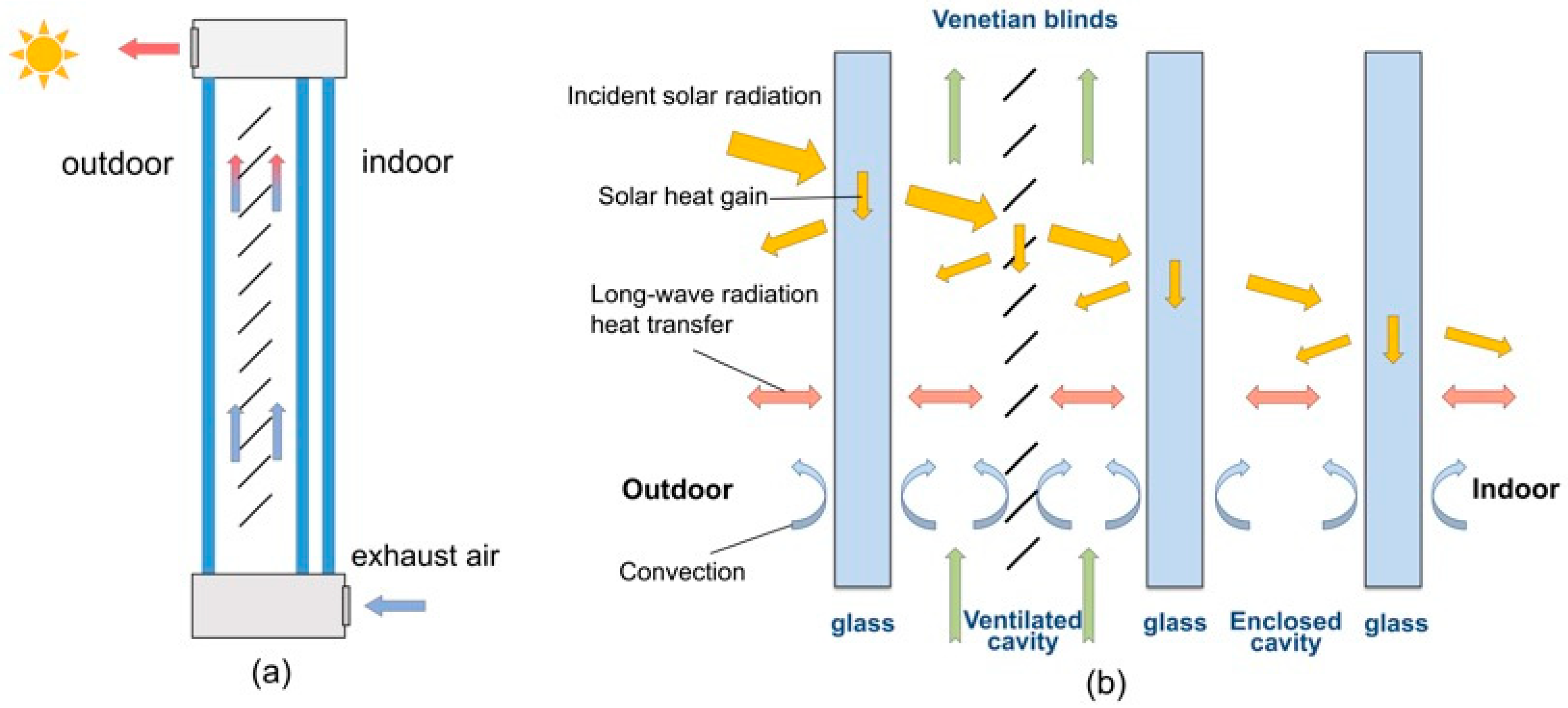
2.2. Numerical Model of EAGU

2.2.1. Energy Balance Equations

As the airflow direction between the glass panels is perpendicular to the direction of heat transfer across the window, a 2-D numerical model is needed to analyze the heat transfer characteristic of the EAGU. In this study, the zonal approach was adopted to discretize the EAGU and calculate its temperature distribution. This approach is widely used to simulate the 2-D heat transfer of thermo-active building envelopes such as the VDSF, liquid flow window, and ventilated wall, and its accuracy has been verified by experimental validation [22,28,40]. In this subsection, the development of the zonal model of EAGU in summer mode is described in detail, and this model can be modified easily to analyze the heat transfer of EAGU in winter. Figure 2 presents the discretization of the EAGU for summer mode. Seven layers in the horizontal direction and M equal sections in the vertical direction were obtained for summer mode. Moreover, the vertical conductive heat transfer was neglected for adjacent zones in each layer for simplification. The thermophysical parameters of each component were regarded as constants. The heat storage of the air was not considered in numerical modeling.
Each section consists of seven zones including three glazing panes (L1, L5, L7), venetian blinds (L3), ventilated air layers at the outside and inside of venetian blinds (L2, L4), and enclosed air layer (L6). Considering the convection, long-wave radiation, and solar radiation, energy balance equations of the seven zones for each section can be developed. In this study, the formulation of energy balance equations is explained in detail for the ith section and can be used to develop the energy balance equations for the whole window. For the ith section, the energy balance equations of seven zones are expressed as follows:
For the exterior glass layer:
h co ( T out T 1 j ) + h ro ( T out T 1 j ) + h c 12 ( T 2 j T 1 j ) + h r 13 ( T 3 j T 1 j ) + h r 15 ( T 5 j T 1 j ) + I sol α 1 = D g ρ g C g T 1 j t
For the ventilated air gap at the outside of the venetian blinds:
h c 12 ( T 1 j T 2 j ) + h c 23 ( T 3 j T 2 j ) + C a ρ a V a 2 ( T 2 j 1 T 2 j ) N H W = 0
For the venetian blinds:
h c 23 ( T 2 j T 3 j ) + h c 34 ( T 4 j T 3 j ) + h r 13 ( T 1 j T 3 j ) + h r 35 ( T 5 j T 3 j ) + I sol α 3 = m s C s T 3 j t N H W
For the ventilated air gap at the inside of the venetian blinds:
h c 34 ( T 3 j T 4 j ) + h c 45 ( T 5 j T 4 j ) + C a ρ a V a 4 ( T 4 j 1 T 4 j ) N H W = 0
For the middle glass layer:
h c 45 ( T 4 j T 5 j ) + h c 56 ( T 6 j T 5 j ) + h r 15 ( T 1 j T 5 j ) + h r 35 ( T 3 j T 5 j ) + h r 57 ( T 7 j T 5 j ) + I sol α 5 = D g ρ g C g T 5 j t
For the enclosed air gap:
h c 56 ( T 5 j T 6 j ) + h c 67 ( T 7 j T 6 j ) = 0
For the interior glass layer:
h c 67 ( T 6 j T 7 j ) + h r 57 ( T 5 j T 7 j ) + h c i ( T i n T 7 j ) + h ri ( T i n T 7 j ) + I sol α 7 = D g ρ g C g T 7 j t
where ρ and C represent the density (kg/m3) and specific heat (J/kgK); D, W, and H represent the thickness, width, and height of the glass panel (m), respectively; m represents the mass of slats in each section (kg); the subscripts of s, g, and a represent the slats, glazing, and air, respectively; hr and hc represent the radiative and convective heat transfer coefficients (W/m2K), respectively; αa represents the overall solar absorptance of the layer La; Va2 and Va4 represent the airflow volume flow at outside and inside of venetian blinds (m3/h), respectively, and Va2 is equal to Va4; Isol represents the normal total incident solar radiation (W/m2K); and Tout and Tin represent the outdoor and indoor air temperature (K), respectively. When reaching an EAGU with a built-in shading device, the incident solar radiation will be partly reflected (γIsol) and partly transmitted (τIsol), and the remaining parts are absorbed by venetian blinds (α3Isol) and three glass panels (α1Isol, α5Isol, α7Isol), respectively. Such a solar transmission process can be expressed as follows:
I sol = γ I sol + α 1 I sol + α 3 I sol + α 5 I sol + α 7 I sol + τ I sol
where γ and τ represent the overall reflectance and overall transmittance of the EAGU, respectively. In this paper, the optical properties of EAGU (γ, α1, α3, α5, α7, and τ) were determined by the WINDOW 7.4 software developed by LBNL [41]. The formulations of the convective and long-wave radiative heat transfer coefficients used in the above equations can be found in our previous study [35].
As the EAGU is segmented into M equal parts, therefore, a total of 7 × M equations can be established for the whole window in summer mode. It should be noted that the built-in shading device of EAGU will be rolled up in winter mode to maximize indoor solar heat gain, therefore, the layer of shading device was neglected in both the physical and numerical models of EAGU in winter mode. Each section of the window then contains five layers, each of which represents the exterior glass panel, ventilated gap, middle glass panel, enclosed gap, and interior glass panel, respectively. Finally, a total of 5 × M equations will be established for the EAGU in winter.
In this study, the EAGU was vertically segmented into 10 portions, which can achieve a compromise between computational efficiency and calculation accuracy. Inputting the boundary conditions (e.g., exhaust airflow rate, indoor/outdoor air temperature, and normal incident solar radiation), the equations can be sequentially solved from the bottom section to the top section to obtain the temperature distribution of EAGU. The iterative process to achieve a converged solution was carried out using a computational procedure built in the MATLAB platform.
Next, the calculated hourly interior surface temperature (Tw) can be used to determine the seasonal cumulative heating (Qw_h) and cooling (Qw_c) energy requirements of the EAGU by Equations (10) and (11), respectively.
Q h = h e a t i n g A [ ( h c i + h p i ) ( T i n T w ) I s o l τ ] d t
Q c = c o o l i n g A [ ( h c i + h p i ) ( T w T i n ) + I s o l τ ] d t
where hri and hci are the long-wave and convective heat transfer coefficients at the interior glass surface (W/m2K); A is the area of EAGU (m2); and t represents the hourly time-step.

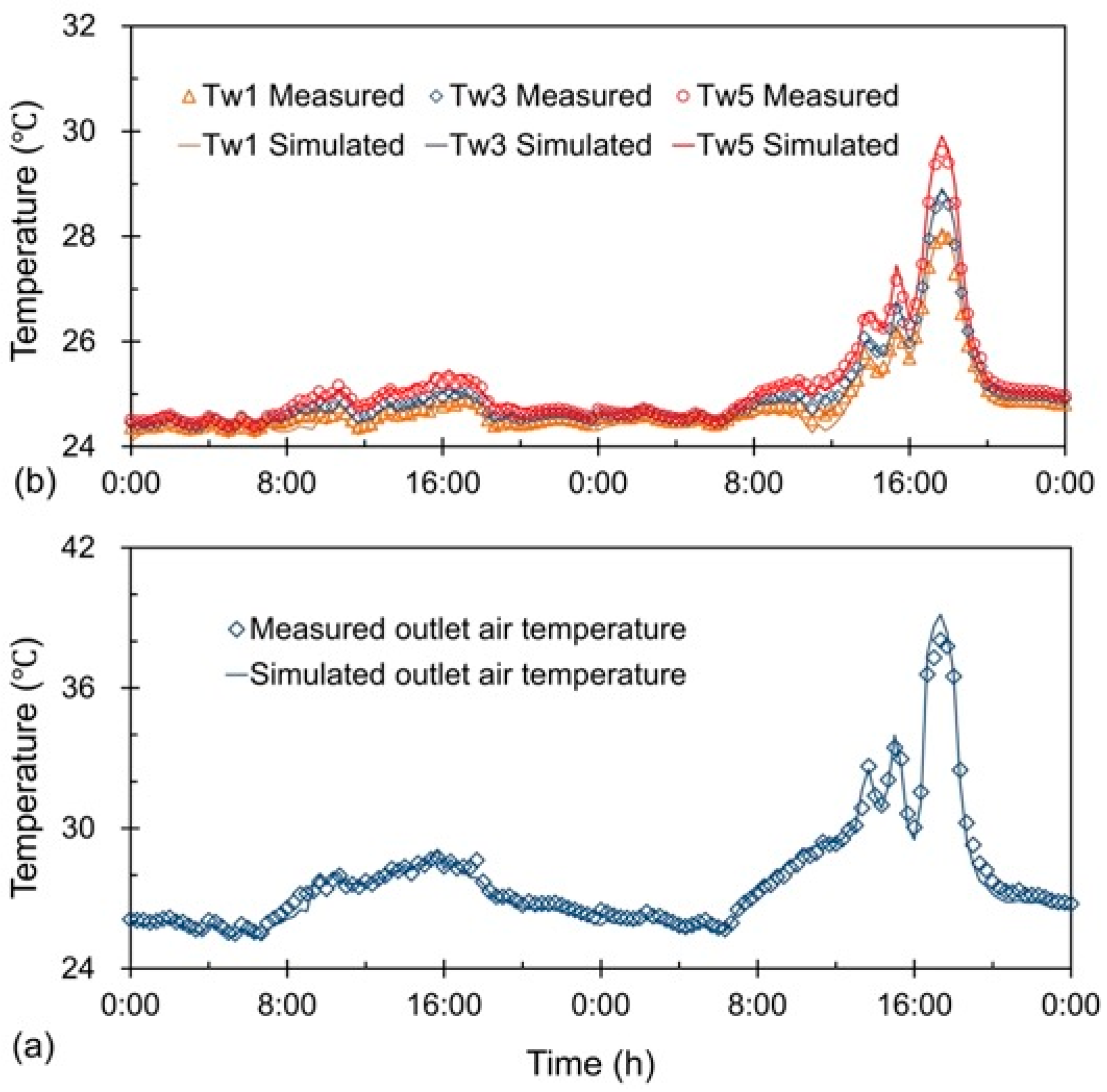
2.2.2. Model Validation

In our previous study, we designed an experimental platform to conduct the experimental analysis of the EAGU [35]. The simulation results were compared to the measured data to ensure that the zonal model was accurate enough. The schematics of the experimental platform and layout of the measurement facilities are illustrated in Figure 3 and Figure 4. To validate the numerical model, the measured boundary conditions were used as the inputs of the computational model, and then the simulated outlet air temperature and interior surface temperatures were compared with the measurement data.
The evolution of the measured and simulated temperatures is presented in Figure 5. The results indicate that the simulated outlet air temperatures and interior surface temperatures were able to completely reproduce the transient variation tendency of measurement, and the deviations in the outputs of the numerical simulation were very limited. The deviations of the simulated interior surface temperatures (Tw1, Tw3, Tw5) were generally within ±0.25 °C, and in the meanwhile, the deviations of simulated outlet air temperatures mainly ranged from −1 °C to 0.5 °C. The proposed zonal model was shown to be accurate enough to analyze the heat transfer of the EAGU. More information about the experimental setup and validation are presented in [35].

2.3. Energy Requirement of Ventilation Fresh Air

Energy consumption due to the ventilation fresh air is influenced by the outdoor and indoor air conditions. In this paper, indoor air temperature and relative humidity were set at 25 °C and 60% in the cooling season and 18 °C and 50% in the heating season, respectively. The hourly outdoor weather data for the annual energy performance evaluation are derived from the TMY database [42].
When the outdoor air temperature is close to the indoor air temperature, the air conditioning system is likely to consume very low energy, so free operations such as free cooling can be activated [43]. In this study, the air conditioning and ventilation system did not work when the air temperature difference between outdoor and indoor was lower than 2 °C. For example, the energy consumption due to the ventilation fresh air need not be considered whenever the outdoor air temperature is higher than 16 °C in winter and lower than 27 °C in summer. The cumulative energy demand to condition the ventilation fresh air with and without heat recovery ventilators can be calculated as follows [44].
Q air = days τ = 8 20 [ ρ a C a ( t e , τ t i ) V a + ρ a L ( d e , τ d i ) V a ] ( t e , τ > 27   ° C , d e , τ > 12.03   g / kg   or   t e , τ < 16   ° C , d e , τ < 6.47   g / kg )
Q air _ total = days τ = 8 20 [ ρ a C a ( t e , τ t i ) ( 1 ε s ) V a + ρ a L ( d e , τ d i ) ( 1 ε l ) V a ] ( t e , τ > 27   ° C , d e , τ > 12.03   g / kg   or   t e , τ < 16   ° C , d e , τ < 6.47   g / kg )
Q air _ sen = days τ = 8 20 [ ρ a C a ( t e , τ t i ) ( 1 ε s ) V a + ρ a L ( d e , τ d i ) V a ] ( t e , τ > 27   ° C , d e , τ > 12.03   g / kg   or   t e , τ < 16   ° C , d e , τ < 6.47   g / kg )
where Qair_sen, Qair_total, and Qair are the energy requirements of the ventilation system installed with SHRV, THRV, and without any heat recovery unit (kWh); ti and di are the indoor temperature (K) and humidity ratio (g/kg); te,τ and de,τ are the outdoor temperature (K) and humidity ratio (g/kg), respectively; L represents the latent heat of vaporization of water (KJ/kg); εs and εl represent the sensible and latent heat recovery efficiency, respectively; Va is the ventilation fresh air rate (m3/h); and τ is the operation time (8 am to 8 pm of every day) of the air-conditioning system; the subscript of days represents the cumulative operation days during the calculation process. According to the national design standard for the energy efficiency of public buildings [45], a minimum effectiveness is required for heat recovery ventilators.

3. Case Studies in Different Climate Conditions

In this study, the heat recovery performance and energy saving potential of the EAGU was assessed and compared with that of the SHRV and THRV in three different climate conditions including a cold climate, hot-summer and warm-winter (HSWW) climate, and hot-summer and cold-winter (HSCW) climate. Outdoor weather data of three representative cities of these climate conditions were derived from the above-mentioned TMY database [42]. Detailed information of the representative cities of three climate zones are listed in Table 2. The design standard of building energy efficiency [45] defined the cooling and heating seasons of these representative cities. The ventilation and air-conditioning system only operated during the working hours of each day (8 a.m. to 8 p.m.). The indoor air state was set at 18 °C and 50% relative humidity (humidity ratio: 6.47 g/kg) in the heating season and 25 °C and 60% relative humidity (humidity ratio: 12.03 g/kg) in the cooling season, respectively.
The weather data (hourly dry bulb temperature and humidity ratio) of the representative cities of cold climate, HSCW climate, and HSWW climate are presented in Figure 6. It can be seen that the weather characteristics of three representative cities showed a significant difference. In this comparative study, the EAGU was composed of a clear single glazing (6 mm) outside, a double-glazing unit (two 6 mm glazing panes with a 12 mm air gap) inside, and a 30 mm ventilated air cavity. For the built-in venetian blinds, the width and distance of slats were 25 mm. The transmittance and reflectance of slats obtained from the material library of WINDOW were 0 and 0.6, respectively. It was assumed that the venetian blinds were closed partially with a 45° tilt angle of slats in summer and rolled-up to a fully opening state for more indoor solar heat in winter, respectively. Moreover, the used double-glazed units for the comparison purpose in case 2 to case 4 had two 6 mm glazing panes with a 12 mm air gap. The calculated optical properties of the EAGU in the cooling and heating seasons are listed in Table 3.
Case studies were conducted to compare the year-round overall window and ventilation systems’ energy consumption of a typical office room (with a size of 5 m length, 4 m width, and 3 m height) employed with the EAGU, SHRV, THRV, and without any heat recovery unit. The ventilation fresh air rates in these four cases were the same. The window systems in four cases had a south-facing orientation with a size of 2 m × 2 m. In this study, the airflow rate in the ventilated air cavity was set to 0.2 m/s for the EAGU, corresponding to a volume flow rate of 43.2 m3/h. For case 1, employing the EAGU as a heat recovery unit, we assumed that all of the exhaust air completely flowed through the EAGU to the ambient. This means that the ventilation fresh air rate of the room is equal to the exhaust air rate of the EAGU.

4. Results and Discussion

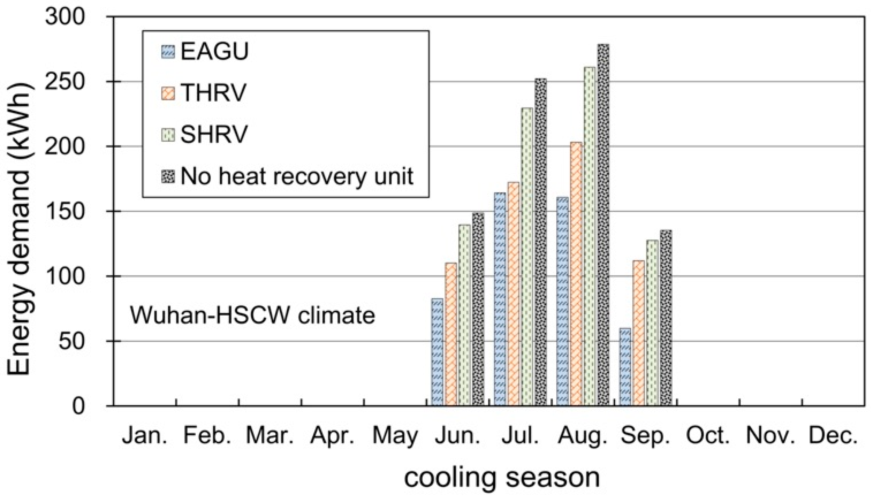
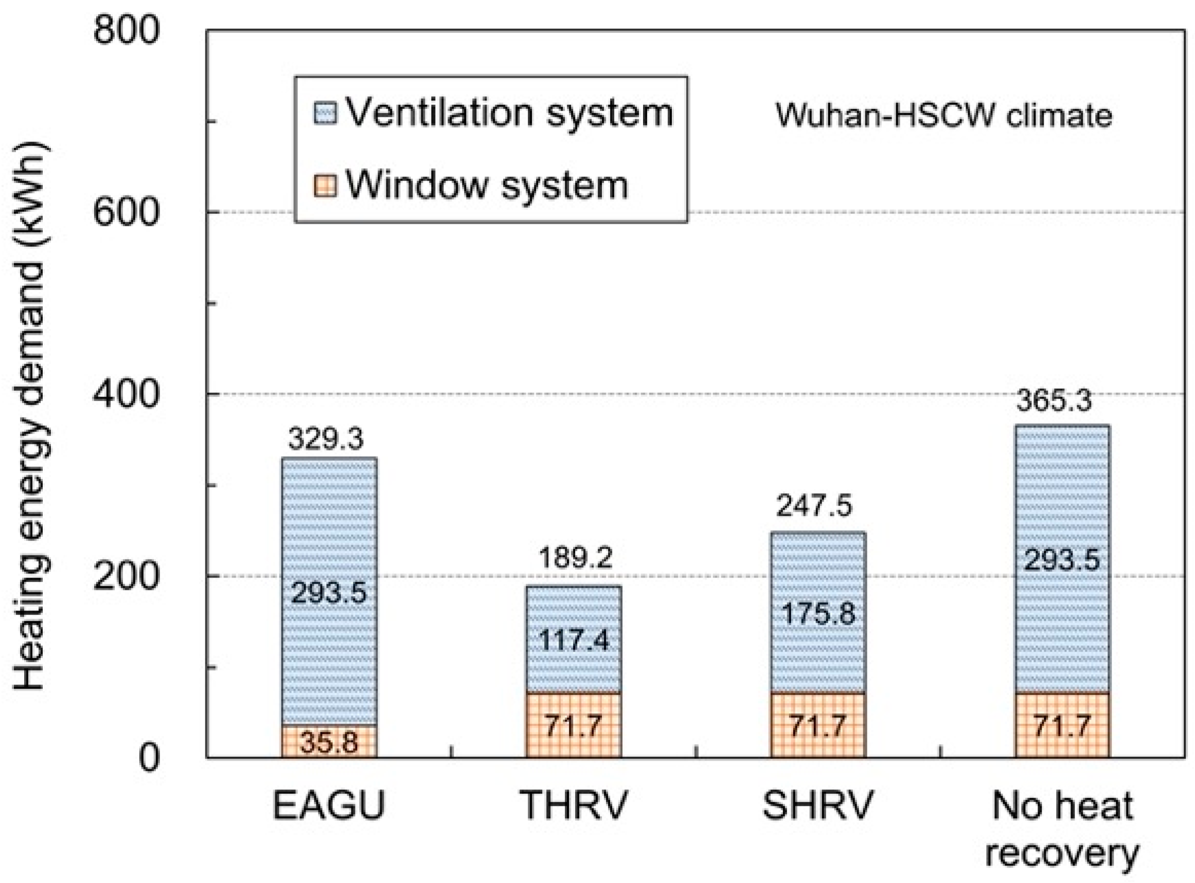
4.1. Year-Round Energy Performance Comparison

This subsection presents the detailed comparative results of year-round overall window and ventilation systems’ energy consumption of the four cases in the HSCW climate. Comparison in different climate conditions will be further described in the next subsection. Figure 7 presents the monthly energy consumption of the four cases in the cooling season. The results indicate that EAGU had a much higher heat recovery potential than THRV and STHR in the cooling season. In August, compared with the THRV and STHR, the use of EAGU could reduce the cooling energy demand from 203.2 kWh and 260.9 kWh to 160.8 kWh, respectively. Moreover, the difference between the energy demands of THRV and SHRV was very apparent in July and August. This is because the outdoor humidity ratio is very high in these two months, and THRV can significantly reduce the energy consumption for dehumidifying the ventilation humid fresh air to the required indoor air state. When the outdoor humidity ratio decreases in September, THRV performs slightly better than SHRV.
The seasonal total energy demand of the four cases in the cooling season of HSCW climate is illustrated in Figure 8. For the case without heat recovery unit, the seasonal total energy demand was 814.8 kWh, with the window and ventilation systems accounting for 452.8 kWh and 362 kWh, respectively. Employing the EAGU as an exhaust air heat recovery unit could reduce the seasonal total energy demand to 476.6 kWh, corresponding to a reduction ratio of 41.5%. For the THRV and SHRV, a reduction ratio of 26.7% and 7% could be achieved, respectively. It can be found that the SHRV shows a limited ability to reduce the overall energy demand. This is mainly because the temperature difference between the indoors and outdoors as well as the sensible cooling load of the ventilation system is relatively low in the cooling season of the HSCW climate. The superior performance of the EAGU resulted from the out-flowing cool exhaust air, which could remove the absorbed solar heat gain of venetian blinds and glass panes and also prevent the heat transferred from the outdoors to indoors in summer. Therefore, compared with the conventional THRV and SHRV, the EAGU facilitates the heat recovery of exhaust air and shows better energy saving potential.
Figure 9 and Figure 10 present the monthly and seasonal total energy demand of the four cases in the heating season of the HSCW climate. The results indicate that the heat recovery performance of the EAGU was inferior to that of the THRV and SHRV in the heating season. Compared with the baseline case without any heat recovery unit, the use of EAGU could reduce the seasonal total energy demand from 365.3 kWh to 329.3 kWh, with a reduction ratio of 9.9%. For the THRV and SHRV, this value could further decrease to 189.2 kWh and 247.5 kWh, achieving a reduction ratio of 48.2% and 32.3%, respectively. Different results could be observed in the cooling and heating seasons. In the heating season, the energy consumption of the ventilation system contributed the main proportion of the overall total energy demand because the temperature difference between the indoors and outdoors was relatively high. Moreover, the window system with a southern orientation could obtain large amounts of indoor solar heat gain during the daytime, which will offset the conductive heat loss through the window to a certain degree. Therefore, to maximize the heat recovery potential of exhaust air, the THRV performed much better than the EAGU in the heating season of the HSCW climate.

4.2. Comparison Results in Different Climate Conditions

The preceding subsection presents the detailed comparative results of different types of exhaust air heat recovery units in the HSCW climate. Therefore, the overall energy saving potential and applicability of the EAGU for different climate conditions were investigated and compared in this subsection. Table 4 summarizes the annual total energy demand of the four cases in climate conditions of cold, HSCW, and HSWW.
It can be found that outdoor climate conditions showed a considerable impact on the energy saving potential and applicability of the EAGU. The energy saving potential of the EAGU ranged from 26.8% and 38.2% for different climate conditions. For the HSWW climate, the annual total energy demand of the EAGU was 714.2 kWh, which achieved a decrease of 95 kWh and 346.4 kWh compared with the THRV and SHRV, respectively. For the HSCW climate, the EAGU performed similar to the THRV. The difference between the annual total energy demands of EAGU and THRV was very small. For the cold climate, the energy saving potential of the THRV was relatively higher than that of the EAGU, but the SHRV was still inferior to the EAGU. The energy saving potential of the EAGU was still desirable in the cold climate. This is mainly because the extremely low outdoor temperature and long heating period of a cold climate will significantly increase the energy demand of the ventilation system. This makes the energy saving potential of the window system inferior to that of the ventilation system.

4.3. Influence of Ventilation Fresh Air Rate

Increasing the ventilation fresh air rate will produce more low-grade exhaust air and increase the energy demand of the ventilation system. In this subsection, the influence of the ventilation fresh air rate on the energy performance of a typical office room employing the EAGU, THRV, SHRV, and without a heat recovery unit was estimated to determine the recommended heat recovery device for different ventilation fresh air rates.
Figure 11 and Figure 12 present the seasonal total energy demand of the four cases in the cooling and heating seasons of the HSCW climate, respectively. The ventilation fresh air rate ranged from 10.8 m3/h to 64.8 m3/h, corresponding to an exhaust airflow rate of the EAGU from 0.05 m/s to 0.3 m/s. The results in Figure 11 indicate that the seasonal total energy demand of the EAGU was consistently lower than that of the THRV and SHRV in the cooling season. However, it should be noted that the difference between the energy demands of EAGU and THRV gradually decreased with the increase in ventilation rate. This difference decreased from 271.4 kWh to 30.9 kWh, when the ventilation rate varied from 10.8 m3/h to 64.8 m3/h.
As shown in Figure 12, the results of the heating season were contrary to those of the cooling season. The energy saving potential of the EAGU is inferior to that of the THRV and SHRV under different ventilation fresh air rates. For the ventilation rate of 10.8 m3/h, the seasonal total energy demand of the EAGU was 121.2 kWh, which was slightly higher than the energy demands of THRV and SHRV. When the ventilation rate increased to 64.8 m3/h compared to the energy demand of EAGU, employing the THRV and SHRV could reduce this value from 471.6 kWh to 247.9 kWh and 335.4 kWh, respectively. To sum up, a higher ventilation rate can further decrease the heat loss or heat gain through the EAGU, but the energy demand reduction in the window system is much lower than the increase in the energy demand to condition the ventilation fresh air.
Figure 13 illustrates the relationship between the ventilation fresh air rate and annual energy saving potential of EAGU, THRV, and SHRV. It can be found that the variation trend of energy saving potential of EAGU was contrary to that of THRV and SHRV. For a low ventilation rate of 10.8 m3/h, the EAGU performed much better than THRV and SHRV. The annual energy saving potential was 14.3% and 6.4% for the THRV and SHRV, respectively. This value could be significantly improved to 50.8% by using the EAGU as a heat recovery unit. When the ventilation rate reached 64.8 m3/h, the THRV showed the highest energy saving potential, and the EAGU still performed much better than the SHRV. It should also be noticed that these must be a critical value of ventilation rate, as shown in Figure 13, which can provide an application guideline about the selection of the heat recovery unit. When the ventilation fresh air rate was lower than this critical value, the EAGU is recommended to maximize the heat recovery potential of exhaust air. Moreover, the THRV is more suitable for the case with a ventilation fresh air rate higher than the critical value. For the cold climate, the energy demand of the ventilation system will contribute to a larger proportion of overall total energy demand compared with the HSCW climate. It can be expected that this critical value of ventilation rate will show a downward trend for the cold climate. Similarly, an upward trend of critical value will be observed for the HSWW climate.

5. Conclusions

The EAGU can act as a heat recovery unit to utilize the exhaust air from conditioned space with a fresh air ventilation system to improve the thermal insulation of the window system. In this study, the year-round energy performance of the EAGU, THRV, and SHRV under various conditions (e.g., ventilation fresh air rate, outdoor weather condition, etc.) were compared to identify whether the use of EAGU is energy-efficient or not, and further discuss the feasibility of its practical application in different climates. The main findings can be concluded as follows. (1) In the cooling season, the energy saving potential of the EAGU performed much better than that of the commonly used THRV and SHRV. However, the EAGU was inferior to the THRV and SHRV in the heating season. (2) Outdoor climate conditions showed a considerable influence on the energy saving potential and applicability of the EAGU. The EAGU is more suitable for application in warm climates, rather than cold climates. (3) There was a critical value of ventilation fresh air rate, which can be used to determine the optimal heat recovery approach to maximize the energy saving potential.
For the practical application of an EAGU, condensation may occur at the interior surface of the outer single glazing in winter, when this glazing surface temperature is lower than the dew-point temperature of indoor exhaust air. Condensation on the glazing surface will cause a foggy visual sense, which is detrimental to the use of EAGU. Therefore, the probability of condensation in winter and effective measures to prevent this condensation should be systematically investigated in our future work. Moreover, a technical-economic analysis and optimization design of using an EAGU in both new buildings or the energy-retrofit of existing buildings will be investigated considering both the investment cost and operation cost to provide some important design guidelines of EAGUs under different scenarios.

Author Contributions

Conceptualization, C.Z.; methodology, C.Z.; software, J.G.; validation, C.Z.; formal analysis, J.G.; investigation, J.G.; resources, C.Z.; data curation, J.G.; writing—original draft preparation, J.G. and C.Z.; writing—review and editing, C.Z.; visualization, J.G.; supervision, C.Z.; project administration, C.Z.; funding acquisition, C.Z. All authors have read and agreed to the published version of the manuscript.

Funding

This research was funded by the Hong Kong Scholars Program (grant number XJ2019044) and the National Natural Science Foundation of China (grant number 51808239).

Institutional Review Board Statement

Not applicable.

Informed Consent Statement

Not applicable.

Data Availability Statement

Not applicable.

Conflicts of Interest

The authors declare no conflict of interest.

References

  1. Liu, Y.; Chen, S.; Jiang, K.; Kaghembega, W.S.H. The gaps and pathways to carbon neutrality for different type cities in China. Energy 2022, 244, 122596. [Google Scholar] [CrossRef]
  2. Lemmet, S. Buildings and Climate Change: Summary for Decision Makers; United Nations Environment Programme—Sustainable Buildings & Climate Initiative: Paris, France, 2009; pp. 1–62. [Google Scholar]
  3. Berardi, U.; Sprengard, C. An overview of and introduction to current researches on super insulating materials for high-performance buildings. Energy Build. 2020, 214, 109890. [Google Scholar] [CrossRef]
  4. Li, A.; Xiao, F.; Zhang, C.; Fan, C. Attention-based interpretable neural network for building cooling load prediction. Appl. Energy 2021, 299, 117238. [Google Scholar] [CrossRef]
  5. Boahen, S.; Anka, S.K.; Lee, K.H.; Choi, J.M. Performance characteristics of a cascade multi-functional heat pump in the winter season. Energy Build. 2021, 253, 111511. [Google Scholar] [CrossRef]
  6. Lyu, W.; Li, X.; Yan, S.; Jiang, S. Utilizing shallow geothermal energy to develop an energy efficient HVAC system. Renew. Energy 2020, 147, 672–682. [Google Scholar] [CrossRef]
  7. Jelle, B.P.; Hynd, A.; Gustavsen, A.; Arasteh, D.; Goudey, H.; Hart, R. Fenestration of today and tomorrow: A state-of-the-art review and future research opportunities. Sol. Energy Mater. Sol. Cells 2012, 96, 1–28. [Google Scholar] [CrossRef] [Green Version]
  8. Arıcı, M.; Tükel, M.; Yıldız, Ç.; Li, D.; Karabay, H. Is the thermal transmittance of air-filled inclined multi-glazing windows similar to that of vertical ones? Energy Build. 2020, 229, 110515. [Google Scholar] [CrossRef]
  9. Somasundaram, S.; Thangavelu, S.R.; Chong, A. Improving building efficiency using low-e coating based retrofit double glazing with solar films. Appl. Therm. Eng. 2020, 171, 115064. [Google Scholar] [CrossRef]
  10. Arıcı, M.; Kan, M. An investigation of flow and conjugate heat transfer in multiple pane windows with respect to gap width, emissivity and gas filling. Renew. Energy 2015, 75, 249–256. [Google Scholar] [CrossRef]
  11. Chen, Y.M.; Xiao, Y.L.; Zheng, S.Q.; Liu, Y.; Li, Y.P. Dynamic heat transfer model and applicability evaluation of aerogel glazing system in various climates of China. Energy 2018, 163, 1115–1124. [Google Scholar] [CrossRef]
  12. Son, H.; Song, T.H. Heat transfer and stress distribution in the central part of vacuum glazing. Appl. Therm. Eng. 2019, 159, 113926. [Google Scholar] [CrossRef]
  13. Baetens, R.; Jelle, B.P.; Gustavsen, A. Properties, requirements and possibilities of smart windows for dynamic daylight and solar energy control in buildings: A state-of-the-art review. Sol. Energy Mater. Sol. Cells 2010, 94, 87–105. [Google Scholar] [CrossRef] [Green Version]
  14. Li, D.; Zhang, C.J.; Li, Q.; Liu, C.Y.; Arıcı, M.; Wu, Y.Y. Thermal performance evaluation of glass window combining silica aerogels and phase change materials for cold climate of China. Appl. Therm. Eng. 2020, 165, 114547. [Google Scholar] [CrossRef]
  15. Wieprzkowicz, A.; Heim, D. Modelling of thermal processes in a glazing structure with temperature dependent optical properties-An example of PCM-window. Renew. Energy 2020, 160, 653–662. [Google Scholar] [CrossRef]
  16. Rezaie, B.; Esmailzadeh, E.; Dincer, I. Renewable energy options for buildings: Case studies. Energy Build. 2011, 43, 56–65. [Google Scholar] [CrossRef]
  17. Shen, C.; Li, X.T. Thermal performance of double skin façade with built-in pipes utilizing evaporative cooling water in cooling season. Sol. Energy 2016, 137, 55–65. [Google Scholar] [CrossRef]
  18. Li, L.; Zhang, C.; Xu, X.; Yu, J.; Wang, F.; Gang, W.; Wang., J. Simulation study of a dual-cavity window with gravity-driven cooling mechanism. Build. Simul. 2022, 15, 1339–1352. [Google Scholar] [CrossRef]
  19. Shen, C.; Li, X.T.; Yan, S. Numerical study on energy efficiency and economy of a pipe-embedded glass envelope directly utilizing ground-source water for heating in diverse climates. Energy Convers. Manag. 2017, 150, 878–889. [Google Scholar] [CrossRef]
  20. Huang, J.C.; Chen, X.; Yang, H.X.; Zhang, W.L. Numerical investigation of a novel vacuum photovoltaic curtain wall and integrated optimization of photovoltaic envelope systems. Appl. Energy 2018, 229, 1048–1060. [Google Scholar] [CrossRef]
  21. Michaux, G.; Greffet, R.; Salagnac, P.; Ridoret, J.B. Modelling of an airflow window and numerical investigation of its thermal performances by comparison to conventional double and triple-glazed windows. Appl. Energy 2019, 242, 27–45. [Google Scholar] [CrossRef]
  22. Li, C.Y.; Lyu, Y.L.; Li, C.M.; Qiu, Z.Z. Energy performance of water flow window as solar collector and cooling terminal under adaptive control. Sustain. Cities Soc. 2020, 59, 102152. [Google Scholar] [CrossRef]
  23. Ghaffarianhoseini, A.; Ghaffarianhoseini, A.; Berardi, U.; Tookey, J.; Li, D.H.W.; Kariminia, S. Exploring the advantages and challenges of double-skin façades (DSFs). Renew. Sustain. Energy Rev. 2016, 60, 1052–1065. [Google Scholar] [CrossRef]
  24. Wang, Y.J.; Chen, Y.M.; Li, C. Airflow modeling based on zonal method for natural ventilated double skin façade with Venetian blinds. Energy Build. 2019, 191, 211–223. [Google Scholar] [CrossRef]
  25. Srisamranrungruang, T.; Hiyama, K. Balancing of natural ventilation, daylight, thermal effect for a building with double-skin perforated facade (DSPF). Energy Build. 2020, 210, 109765. [Google Scholar] [CrossRef]
  26. Akbarpoor, A.M.; Poshtiri, A.H.; Biglari, F. Performance analysis of domed roof integrated with earth-to-air heat exchanger system to meet thermal comfort conditions in buildings. Renew. Energy 2021, 168, 1265–1293. [Google Scholar] [CrossRef]
  27. Zhang, C.; Wang, J.B.; Xu, X.H.; Zou, F.X.; Yu, J.H. Modeling and thermal performance evaluation of a switchable triple glazing exhaust air window. Appl. Therm. Eng. 2016, 92, 8–17. [Google Scholar] [CrossRef]
  28. Zanghirella, F.; Perino, M.; Serra, V. A numerical model to evaluate the thermal behaviour of active transparent façades. Energy Build. 2011, 43, 1123–1138. [Google Scholar] [CrossRef]
  29. Takemasa, Y.; Togari, S.; Miura, K.; Katoh, M.; Hiraoka, M.; Owada, J. Evaluation of calculation models for predicting thermal performance of various window systems. ASHRAE Trans. 2013, 119, 1B. [Google Scholar]
  30. Zhang, C.; Gang, W.J.; Wang, J.B.; Xu, X.H.; Du, Q.Z. Numerical and experimental study on the thermal performance improvement of a triple glazed window by utilizing low-grade exhaust air. Energy 2019, 167, 1132–1143. [Google Scholar] [CrossRef]
  31. Skaff, M.C.; Gosselin, L. Summer performance of ventilated windows with absorbing or smart glazings. Sol. Energy 2014, 105, 2–13. [Google Scholar] [CrossRef]
  32. Chow, T.T.; Li, C.Y.; Lin, Z.; Fong, K.F.; Pei, G. Experimental evaluation of ventilated glazing performance in Hong Kong. Int. J. Energy Res. 2009, 33, 526–537. [Google Scholar] [CrossRef]
  33. Kim, M.H.; Oh, C.Y.; Hwang, J.H.; Choi, H.W.; Yang, W.J. Thermal performance of the exhausting and the semi-exhausting triple-glazed airflow windows. Int. J. Energy Res. 2006, 30, 177–190. [Google Scholar] [CrossRef]
  34. Ismail, K.A.R.; Henriquez, J.R. Simplified model for a ventilated glass window under forced air flow conditions. Appl. Therm. Eng. 2006, 26, 295–302. [Google Scholar] [CrossRef]
  35. Zhang, C.; Gang, W.J.; Wang, J.B.; Xu, X.H.; Du, Q.Z. Experimental investigation and dynamic modeling of a triple-glazed exhaust air window with built-in venetian blinds in the cooling season. Appl. Therm. Eng. 2018, 140, 73–85. [Google Scholar] [CrossRef]
  36. Khalvati, F.; Omidvar, A. Summer study on thermal performance of an exhausting airflow window in evaporatively-cooled buildings. Appl. Therm. Eng. 2019, 153, 147–158. [Google Scholar] [CrossRef]
  37. Bao, L.L.; Wang, J.G.; Yang, H.X. Investigation on the performance of a heat recovery ventilator in different climate regions in China. Energy 2016, 104, 85–98. [Google Scholar] [CrossRef] [Green Version]
  38. Gil-Baez, M.; Barrios-Padura, A.; Molina-Huelva, M.; Chacartegui, R. Natural ventilation systems in 21st-century for near zero energy school buildings. Energy 2017, 137, 1186–1200. [Google Scholar] [CrossRef]
  39. Shahsavar, A.; Khanmohammadi, S. Feasibility of a hybrid BIPV/T and thermal wheel system for exhaust air heat recovery: Energy and exergy assessment and multi-objective optimization. Appl. Therm. Eng. 2019, 146, 104–122. [Google Scholar] [CrossRef]
  40. Zhang, C.; Xiao, F.; Wang, J.B. Design optimization of multi-functional building envelope for thermal insulation and exhaust air heat recovery in different climates. J. Build. Eng. 2021, 43, 103151. [Google Scholar] [CrossRef]
  41. US Department of Energy. Lawrence Berkeley National Laboratory. WINDOW 7.4. Available online: https://windows.lbl.gov/software/window (accessed on 21 April 2022).
  42. China Meteorological Bureau, Climate Information Center, Climate Data Office and Tsinghua University, Department of Building Science and Technology. China Standard Weather Data for Analyzing Building Thermal Conditions; China Architecture and Building Press: Beijing, China, 2005. [Google Scholar]
  43. Wei, J.; Zhao, J.; Chen, Q. Energy performance of a dual airflow window under different climates. Energy Build. 2010, 42, 111–122. [Google Scholar] [CrossRef] [Green Version]
  44. Zhong, K.; Kang, Y. Applicability of air-to-air heat recovery ventilators in China. Appl. Therm. Eng. 2009, 29, 830–840. [Google Scholar] [CrossRef]
  45. Ministry Housing and Urban-Rural Development of People’s Republic of China. Design Standard for Energy Efficiency of Public Buildings (GB50189-2015); Architecture & Building Press: Beijing, China, 2015.
Figure 1. Schematic and principle of the EAGU: (a) configuration; (b) heat transfer process.
Energies 15 03116 g001
Figure 2. Discretization of the EAGU in summer.
Energies 15 03116 g002
Figure 3. Overview of the experimental platform of the EAGU [35]. Reprinted with permission from ref. [35]. Copyright 2018 Elsevier.
Energies 15 03116 g003
Figure 4. Layout of the measurement facilities [35]. Reprinted with permission from ref. [35]. Copyright 2018 Elsevier.
Energies 15 03116 g004
Figure 5. Comparison of the simulated and measured temperatures of (a) outlet air and (b) interior surface of the EAGU.
Energies 15 03116 g005
Figure 6. Hourly weather conditions of the three different climate zones: (a) dry bulb temperature; (b) humidity ratio.
Energies 15 03116 g006
Figure 7. Monthly energy demand of the four cases in the cooling season.
Energies 15 03116 g007
Figure 8. Seasonal total energy demand of the four cases in the cooling season.
Energies 15 03116 g008
Figure 9. Monthly energy demand of the four cases in the heating season.
Energies 15 03116 g009
Figure 10. Seasonal total energy demand of the four cases in the heating season.
Energies 15 03116 g010
Figure 11. Effect of the ventilation fresh air rate on energy demand of the four cases in the cooling season.
Energies 15 03116 g011
Figure 12. Effect of the ventilation fresh air rate on energy demand of the four cases in the heating season.
Energies 15 03116 g012
Figure 13. Effect of ventilation fresh air rate on the energy saving potential of different exhaust air heat recovery units in the HSCW climate.
Energies 15 03116 g013
Table 1. Different types of exhaust air heat recovery units to be compared.
Type of Heat RecoveryWindow SystemHeat Recovery Ventilator
Case 1EAGUEAGUwithout
Case 2SHRVDouble glazed unitSHRV
Case 3THRVDouble glazed unitTHRV
Case 4withoutDouble glazed unitwithout
Table 2. Detailed information of the three climate conditions.
Climate ConditionCold ClimateHot-Summer and Cold-Winter (HSCW) ClimateHot-Summer and Warm-Winter (HSWW) Climate
Representative cityBeijingWuhanGuangzhou
Cooling season15 June to 15 September1 June to 30 September1 May to 30 September
Heating season15 November to 15 March15 December to 15 March1 December to 28 February
Location39°56′ N, 116°20′ E30°36′ N, 114°17′ E23°06′ N, 113°16′ E
Table 3. Optical properties of the EAGU in cooling and heating seasons [30]. Reprinted with permission from ref. [30]. Copyright 2019 Elsevier.
SeasonOverall AbsorptanceTransmittanceReflectance
Exterior GlassVenetian BlindsMid-GlassInterior Glass
Summer0.1340.31370.03750.02630.22150.2668
Winter0.1134NA0.08530.06380.57610.1614
Table 4. Annual total energy demand of the four cases in different climate conditions.
Climate ConditionAnnual Total Energy Demand (kWh)Energy Saving Potential Compared with No Heat Recovery Unit
EAGUTHRVSHRVNo Heat Recovery UnitEAGUTHRVSHRV
Cold939.9801.210331284.526.8%37.6%19.6%
Hot-summer and cold-winter (HSCW)796.9786.810051180.132.5%33.3%14.8%
Hot-summer and warm-winter (HSWW)714.2809.21060.6115638.2%30.0%8.3%
Publisher’s Note: MDPI stays neutral with regard to jurisdictional claims in published maps and institutional affiliations.

