Abstract
In this study, maximum power point tracking (MPPT) control of a grid-connected doubly fed induction generated (DFIG)-based wind energy conversion system (WECS) at variable wind speed was designed and analyzed. The real wind speed data of the Edremit/Balıkesir region in Turkey was used as the wind speed profile. A N90/2.5 MW wind turbine model of Nordex Company was used in the study. Firstly, a conventional PI controller was applied to both rotor and grid side converters. The rotor-side converter (RSC) controls the power generated from the DFIG, whereas the grid-side converter (GSC) controls the DC bus voltage. An MPPT controller was applied to the RSC to generate reference torque at instant variable wind speeds. Thus, the system’s response time, electromagnetic torque, generated power, and grid-side currents parameters were improved. In the MPPT controller, the reference torque value is produced by using the angular velocity and reference angular velocity values of the DFIG. The proposed system was modeled and simulated in Matlab/Simulink. Generated power, DC bus voltage, response time, electromagnetic torque, and grid side currents results were obtained. The results of the conventional PI controller and the results of the PI controller with MPPT were compared. The results of the proposed control were also compared with the related studies. The results showed that the proposed system is reliable, applicable, and valid for the grid-connected DFIG at variable wind speeds.
1. Introduction
WECS are becoming widespread in recent years owing to the reduction in production costs and developments in electronic technologies. Environmental problems such as greenhouse gas emissions and air pollution are increasing all around the world. Increasing environmental concerns have raised the attention in WECS [1]. The growing share of wind energy production, in the actual power system, has caused new occasions and difficulties. One of the important criteria of WECS is to ensure that the system generates the desired power under variable wind speed conditions and can respond quickly to wind speed changes. To meet these criteria, various control strategies were applied to the RSC and GSC interfaced by the DC-BUS in the literature. WECS consists of different types of generators such as permanent magnet synchronous generators (PMSG) and DFIG to produce electrical energy from wind energy [2]. Among the generators used in WECS, DFIG is the most suitable due to its many advantages over other turbines [3]. The power electronics converters used in DFIG control about 20–30% of the total generated power. This is the major advantage of DFIG. The losses in power electronics equipment and the costs of converters are higher for direct-drive synchronous generators (i.e., PMSG). The DFIG is used particularly in variable-speed wind turbine (VSWT) systems with a static converter linked between the rotor and the stator. Currently, this method covers almost 50% of WECS technologies [4]. Various algorithms are used in wind energy conversion systems. The MPPT algorithm is one of these algorithms. MPPT algorithms are widely used in renewable energy conversion systems such as PV systems and WECS. The main purpose of the MPPT algorithm is to obtain the maximum power from the WECS. MPPT algorithms can be divided into two main parts: direct power control (DPC) and indirect power control (IPC). In the IPC technique, the generated power is pre-calculated by means of the wind speed graphs, while in the DPC, the electrical power is directly examined so that the wind turbine can produce at the maximum power point [5,6]. In this paper, the IPC method was used while designing the proposed system. Direct power control (DPC) techniques were implemented to the DFIG-based WECS on Matlab/Simulink for different tests. The simulation results demonstrate that the robustness and response time of the system are improved [7]. The adaptive neuro-fuzzy inference-method-based MPPT control was added to the wind energy conversion system and the test results were compared with the traditional PI controller [8]. The fractional-order PI controller (FOPI) technique is practiced for the control of pitch angle to enhance the DFIG capacity at the upper wind speed of 18 m/s [9]. Another technique commonly used in the control of wind energy conversion systems is the sliding mode technique. It is robust to changes in system parameters and limited changes in external disturbances. Therefore, it is widely applied in wind energy conversion systems with squirrel cage induction generators [10]. This paper examines the performance of a WECS under breakdowns in the lubricant system and DC/DC converter failure. The breakdown causes the maximum power point (MPP) of the WECS to be lesser [11]. This paper offered a developed invasive weed optimization (IIWO) to produce an improved sliding mode extremum seeking control (SMESC) parameters. The technique developed a novel stochastic reproductive strategy to improve its robustness and chasten the coding phase [12]. Back-to-back converters of the DFIG were controlled by the flux oriented control (FOC) using a PI controller and sliding mode technique (SMT) on Matlab/Simulink environment. The two techniques were compared in terms of the power transmitted to the grid and the power generated by the system [13]. The integral sliding mode control (ISMC) is applied for low-rated wind speed conditions whereas a PI control is applied for high-rated wind speed conditions in [14]. The integrated MPPT-pitch angle control algorithm is performed for a VSWT system. The accuracy of the developed system was verified with simulation results in Matlab/Simulink environment [15]. With a proposed control scheme, loss minimization (LM) and MPPT are assembled in DFIG. Hence, maximum power generation is provided with the same level of wind energy potential [16]. The predictive model [PM] method was introduced as a better direct power control applied to DFIG-based WECS [17,18]. The designed adaptive controller which uses fuzzy logic-PI is adapted for RSC of DFIG-based WECS in [19]. A grid-connected DFIG-based WECS was tested at constant wind speeds with different transmission line lengths. The results were compared in terms of reactive power, active power, and power factor. It was emphasized that the increase in transmission line length affects the system negatively in terms of reactive power, and this can be solved with power electronics solutions [20]. The rotor and stator voltages, rotor speed, and torque values of the DFIG-based WECS are balanced with the MPPT controller based on the maximum tip speed ratio. The response of the system to variable speeds and reactive power change was investigated in [21].
The main focus of the present study is to enhance the response time of the WECS at variable wind speeds. For this aim, a grid-connected variable speed DFIG-based WECS was designed using Matlab/Simulink. The Nordex N90/2.5 MW wind turbine was used as a turbine model in the designed system. Real wind speed data of the Edremit/Balıkesir region in Turkey were used in simulations. To obtain the targeted power with a fast response time in the variable speed wind energy conversion system (VS-WECS), PI control was applied to the converter on the rotor side and the converter on the grid side. Then, MPPT control was added to the RSC to improve the response time and ensure that the generated power is fully compatible with the power curve of the DFIG. With the help of the MPPT controller added to the RSC, more accurate reference torque (Tem*) values were generated compared with the conventional PI controller. In this way, the response time of the system was improved, and the targeted power generation was achieved. The performance of the proposed system using MPPT control with PI was compared with a conventional PI controller in terms of response time, generated power, electromagnetic torque, grid current, and DC bus voltage parameters. The results of the proposed control system are also compared with similar research presented in [7,8,15]. Simulation results demonstrated that the proposed system offers better response time and can produce power at desired values successfully. The proposed system is reliable, applicable, and rapid for grid-connected DFIG at variable wind speeds.
The main contributions of the study are listed as follows:
- Real wind speed profiles, a commercial DFIG model, and an actual grid model of the studied region were used.
- An MPPT controller was applied to the rotor side converter to generate reference torque.
- Response time, produced power, electromagnetic torque, and grid-side currents parameters were improved with the proposed controller.
2. Wind Energy Conversion System
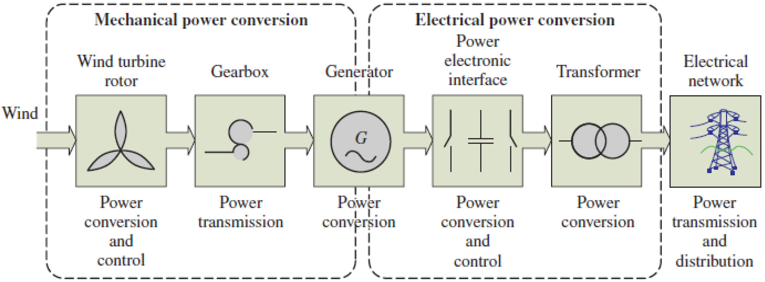
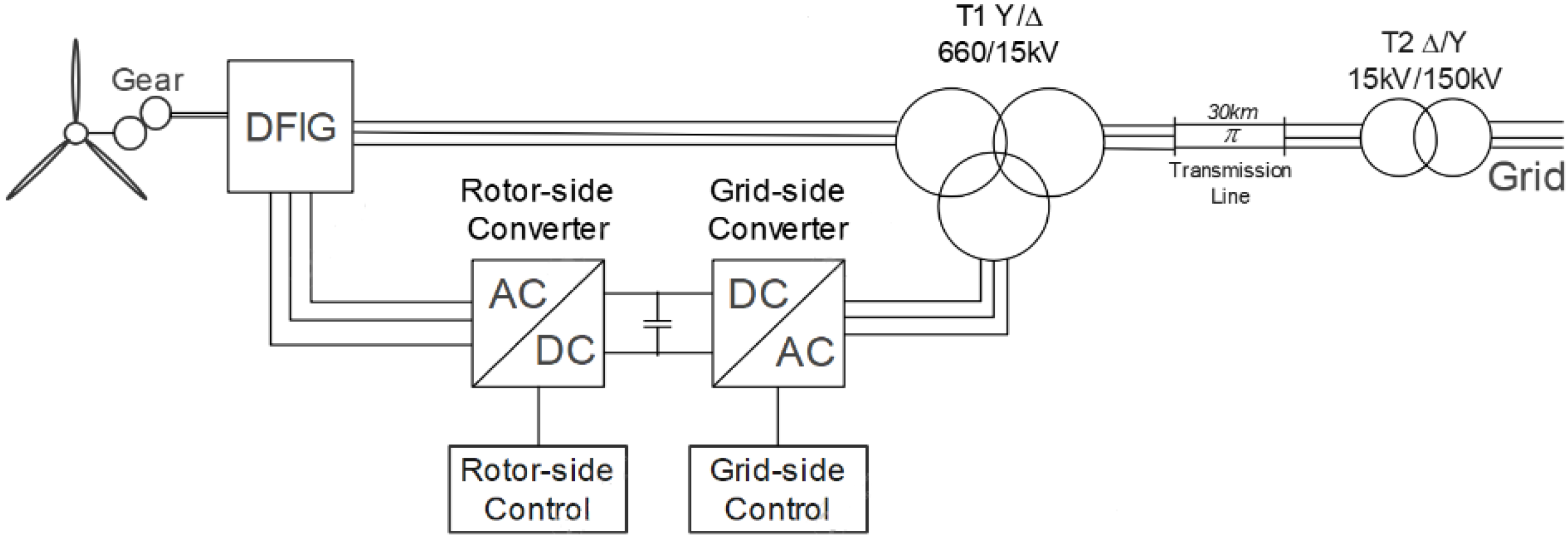
The WTS catches wind power with the help of blades and transforms it into mechanical turning power in the shaft. One of the best solutions to convert the high-torque, low-speed, mechanical power is using a gearbox [22]. A block diagram of the generation of electrical power from wind power in a wind turbine is shown in Figure 1 [23].
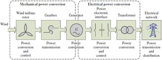
Figure 1.
Converting wind power into electrical power with a wind turbine.
The electrical energy generated by the generator is controlled by power electronic elements. Then, it is increased to the desired voltage value using transformers and transferred to the network with the help of transmission lines.
Wind turbines are examined in two groups: variable speed wind turbines (VSWT) and fixed speed wind turbines (FSWT), depending on their different operating characteristics at different wind speeds [24]. In FSWT, the generator is directly connected to the grid. Until the rotor speed catches the grid frequency, it creates uncontrollable fluctuations in the energy obtained from the wind. These fluctuations negatively affect the power quality of the grid [25]. In VSWT, rotor speed and generator can be controlled by power electronics. Using this control, power fluctuations caused by wind changes can be minimized by changing the rotor speed [26].
2.1. Aerodynamic Model of Wind Turbine
The aerodynamic model of the wind turbine represents the power generated by the rotor and the calculation of the mechanical torque, which is a function of the airflow over the blades [27].
Turbines generate torque while obtaining mechanical energy from the kinetic energy of the wind. The energy of the wind is in the state of kinetic energy, so the magnitude of its kinetic energy is affiliated with the air density and wind speed [28]. The following equations represent the torque (1) and power (2) generated by the rotor:
The power coefficient (Cp) represents the ratio of kinetic energy converted by the wind turbine into mechanical energy. This ratio is a function of the tip speed ratio (λ) and is dependent on the blade pitch angle for turbine systems.
The tip speed ratio (3) can be expressed as follows [29]:
By combining Equation (3) with (2) we have:
Here, ρ represents the air density, A represents the area swept by the rotor blades (in m2), Cp represents the power coefficient, and Vv represents the wind speed. Hereby, if the wind speed, air density, and swept area are constant, the turbine’s aerodynamic output power is identified by the power factor of the WTS. The power produced by the turbine can also be controlled by changing the blade angle (β). In this way, maximum power point tracking can be provided. When β is constant, Cp behaves like a nonlinear function of λ [30]. In this paper, the blade angle is assumed to be constant, as seen in Equation (4).
2.2. DFIG Model
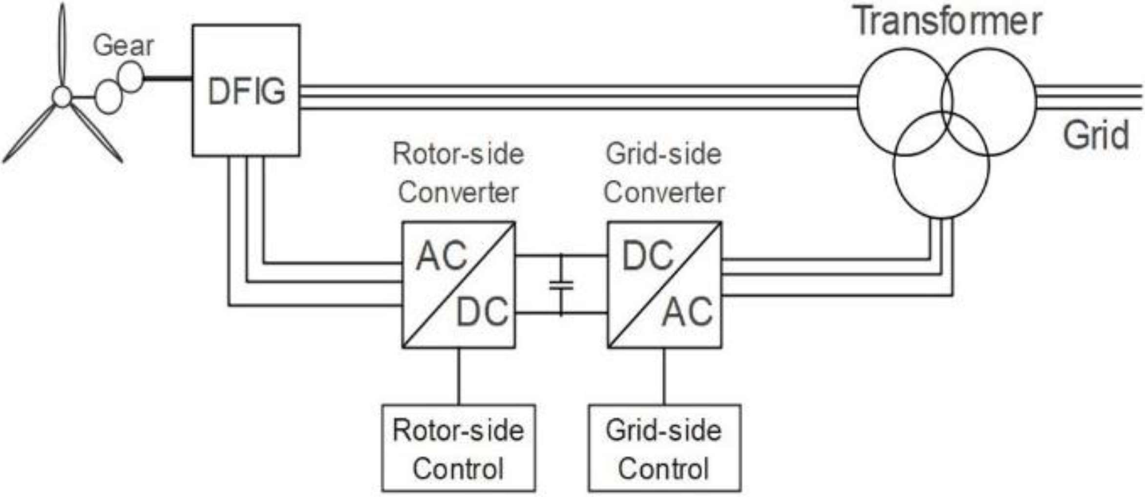
In recent years, the doubly fed induction machine (DFIG), also called wound rotor induction machine (WRIM), has been widely used at the level of megawatts in wind energy conversion systems (WECS). A classical grid-connected DFIG-based WECS is shown in Figure 2.
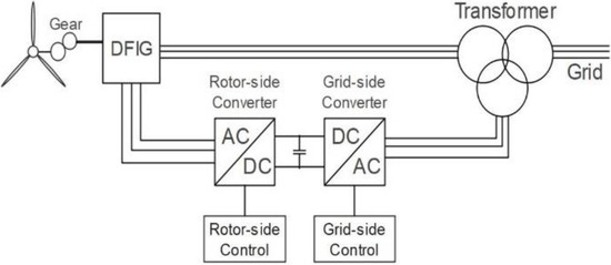
Figure 2.
Grid-connected DFIG-based WECS.
In this system, the stator windings are directly connected to the grid, meanwhile, the rotor windings are connected to the grid via power electronics converters. These converters consist of two voltage source inverters with bidirectional current flow, switching with pulse width modulation (PWM). While generated power control is performed by the RSC, the DC bus voltage is kept constant with the GSC. While constant amplitude and constant frequency energy are taken from the three-phase stator windings of the DFIG connected to the grid, energy with variable amplitude and variable frequency is implemented to the rotor windings with the help of converters. The proposed system is designed using Matlab/Simulink, considering the conventional grid-connected DFIG-based WECS shown in Figure 2.
2.3. Dynamic Model of DFIG
Important features of the DFIG dynamic model are as follows: the stator windings are spread evenly around the stator and the flux change in the air gap is assumed to be sinusoidal. The 3-phase stator windings are placed at an angle of 120 degrees [31]. Iron losses are neglected and the permeability of the magnetic parts is considered infinite. The skin effect is neglected. The variation of resistors and inductances with temperature and frequency are neglected [32].
In making up the dynamic model (αβ) of the doubly fed induction machine (DFIM), space vector theory (SVT) is implemented to the basic electric formulations of the machine model. Therefore, the 3-phase of the rotor and stator, by using SVT, can be represented by 2-phase equations.
The space vector modulation (SVM) of the DFIM can be also shown in the dq frame. When obtaining the voltage equations in the dq frame, e−jθs and e−jθr are multiplied by Equations (5) and (6), respectively:
Similarly, the fluxes yield:
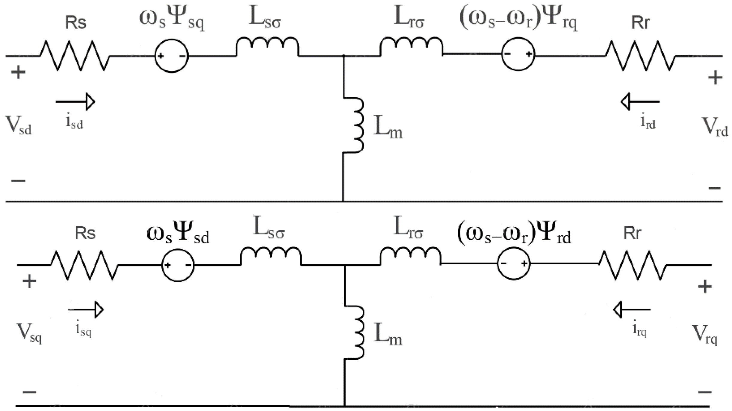
The DFIG’s equivalent circuit in dq can be achieved using Equations (7)–(14) [33] as shown in Figure 3. All magnitudes in the equivalent circuit are reduced to the stator part.

Figure 3.
DFIG: d and q axis equivalent circuits.
Here, Vds, Vqs stator voltages in dq axis set and Vdr, Vqr rotor voltages in dq axis set, isd, isq stator currents in dq axis set and idr, iqr rotor currents in dq axis set, Lsσ, Lrσ, Lm stator in dq axis set, rotor leakage inductance and magnetization inductance values, Rs, Rr stator and rotor resistances in dq axis set, ωs, ωr stator and rotor electrical speeds in dq axis set, Ψds, Ψqs, Ψdr, Ψqr, respectively, and stator and rotor flux in dq axis set.
While the equivalent circuit modeling of DFIG was designed, the circuit model was reduced from a 3-phase system to a 2-phase system as shown in Figure 3, reducing its complexity and making it easier to transfer it to the simulation environment. These equivalent circuits were used when designing the block diagrams of the GSC and RSC, which will be explained in the following sections.
3. Reference Frame and Transformation
To create the control structure of the DFIG, it is necessary to know the general mathematical equations of the asynchronous machines. The mathematical model to be created should have a structure that can accurately reflect the temporary and steady-state characteristics of the induction generator. DFIG equations are given by defining the dq axes rotating at synchronous speed. Before the model is expressed, the abc-αβ and synchronously rotating abc-dq transformations concerning a phase are provided [34].
3.1. Clarke (abc-αβ) Transformation Matrices
With the transformation technique known as Clarke transform, the 3-phase machine model with a 120-degree phase difference was reduced to a 2-phase called αβ axes with a 90-degree phase difference. The machine transformation matrix model converted from 3-phase to 2-phase is expressed in Equation (15) and the matrix model converted from 2-phase to 3-phase is expressed in Equation (16) [35]:
3.2. Park (abc-dq) Transformation Matrices
Clarke and Park’s transformations are expressed in matrix form and realized the conversion from the 3-phase machine model directly to the machine model in the 2-phase dq axis set with the matrix. The abc-dq transformation and the dq-abc transformation are expressed in Equations (17) and (18), respectively [36]:
In addition, the transformation of the machine model can be obtained with the αβ axis matrix into the dq axes of the rotor axes (19), (20):
These equations are processed in the GSC and RSC used in the proposed control system of the variable speed grid-connected DFIG-based WECS.
4. Control of DFIG-Based Wind Energy System
To control the DFIG, the RSC and GSC of the system must first be designed in Matlab/Simulink. RSC and GSC structures are designed using the transformation equations and equivalent circuits mentioned in the previous section. The role of the RSC is to control generated power. The duty of the GSC is to control the bi-directional transfer of power flow from the grid to the rotor or from the rotor to the grid by keeping the DC bus voltage constant [37].
In this section, first of all, two control structures for the RSC control and the GSC control of the DFIG will be examined in detail, and the control structures for these two converters are given in the next section.
4.1. Control of Rotor-Side Converter (RSC)
There are various control methods for RSC control. Direct vector control concerning stator flux or stator voltage is a basic method for DFIG control. In addition, indirect vector control and direct torque control methods are used. Stator and rotor flux orientation are used in the direct vector control, indirect vector control, and direct torque control methods. In the vector control method (VCM) using rotor flux orientation, the amplitude and angle of the rotor flux are calculated. The calculated angle of the rotor flux is used in 3-phase to 2-phase and 2-phase to 3-phase conversions. The difference between direct and indirect VCMs is the method of obtaining these values [38].
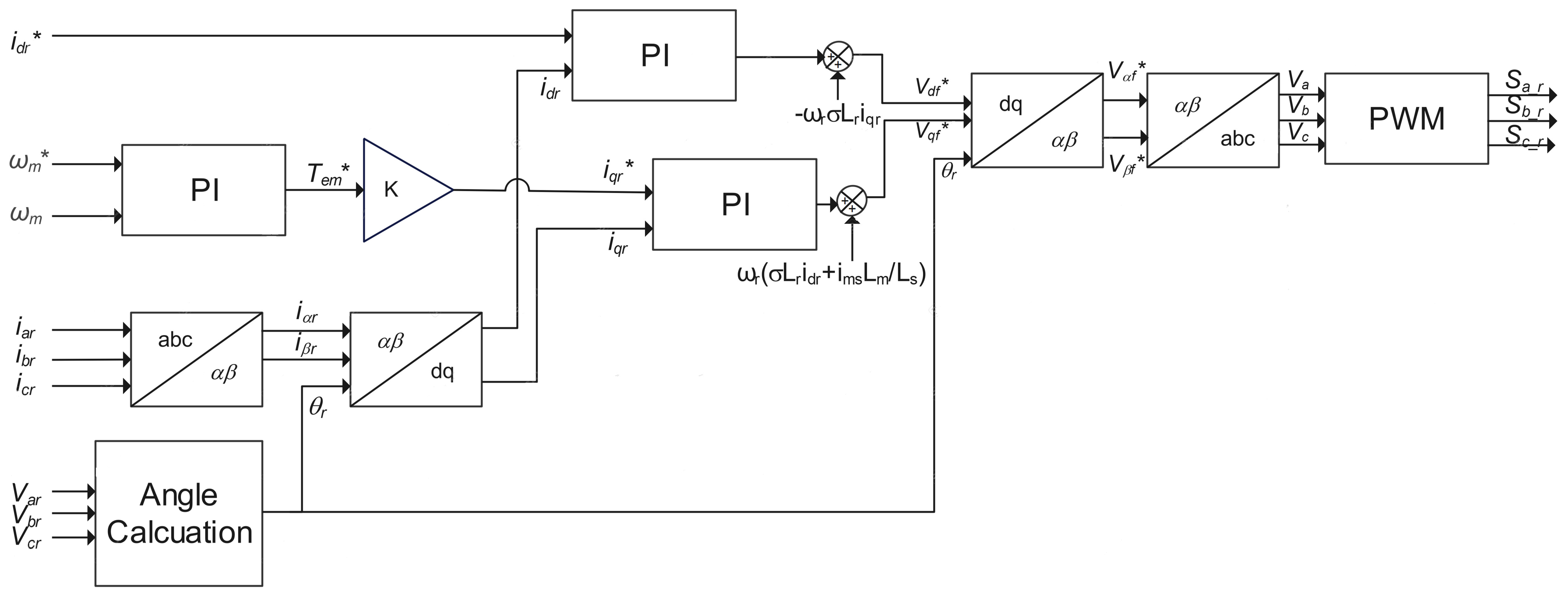
The vector control for RSC illustrated in Figure 4 is based on the principle of dq axis transformations. Using the conversion technique of the 3-phase generator model variables, they can be controlled independently of each other by transforming them into dq axes with 90-degree differences.
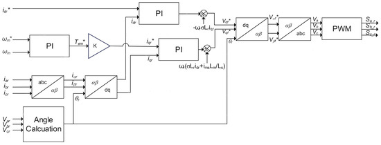
Figure 4.
Vector control of rotor-side converter.
4.2. Control of Grid-Side Converter (GSC)
VCM oriented from the grid voltage can be applied by applying abc-dq transformations as in RSC. Equations of the VCM for the GSC are expressed in (21) and (22):
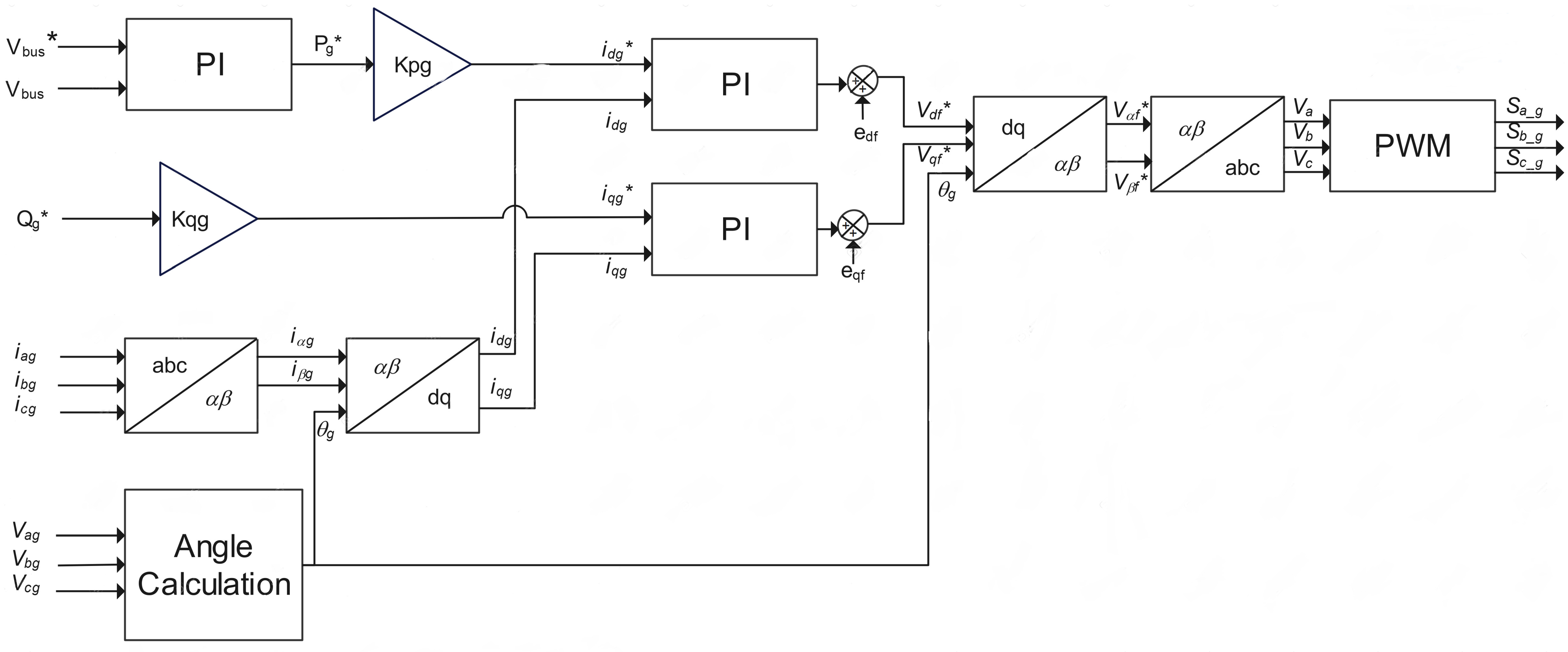
Here, Vdinv, Vqinv represents the voltage produced by the inverter, Vgd, Vgq represents the grid voltage, igd, igq the grid currents, R the resistance of the grid, Lg the line inductance of the grid, and ωg the angular velocity of the grid. Figure 5 infers the vector control block diagram of GSC.
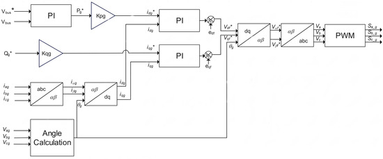
Figure 5.
Vector control of grid-side converter.
Vd* and Vq* voltage references can be obtained by performing current control with the help the of PI controller. The DC voltage is also controlled by the DC voltage control used in the upper loop. In active power, DC varies according to the change in id controlling the voltage.
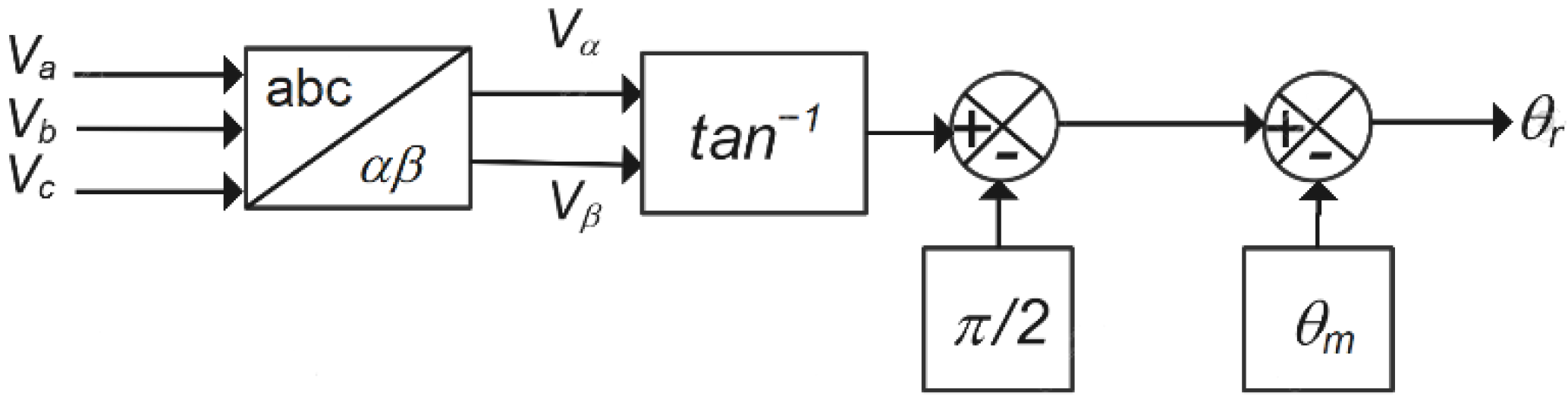
The grid voltage’s angle is determined with the help of Equation (23) and the block diagram of the angle calculation of the rotor-side voltage is given in Figure 6. With the help of Equation (23) and the block diagram illustrated in Figure 6, the angle of the voltage can be calculated:
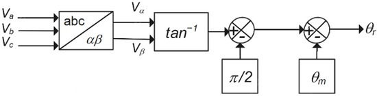
Figure 6.
Angle calculation block diagram of the rotor-side converter.
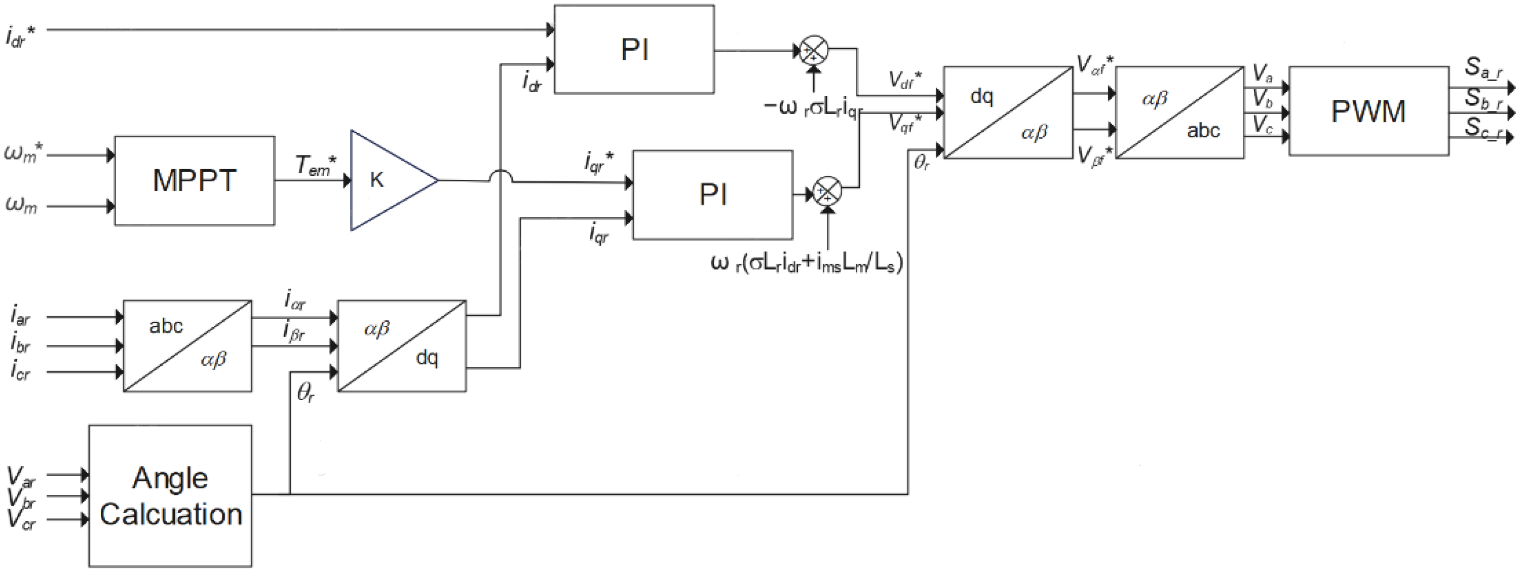
4.3. Proposed Control of Rotor-Side Converter (RSC)
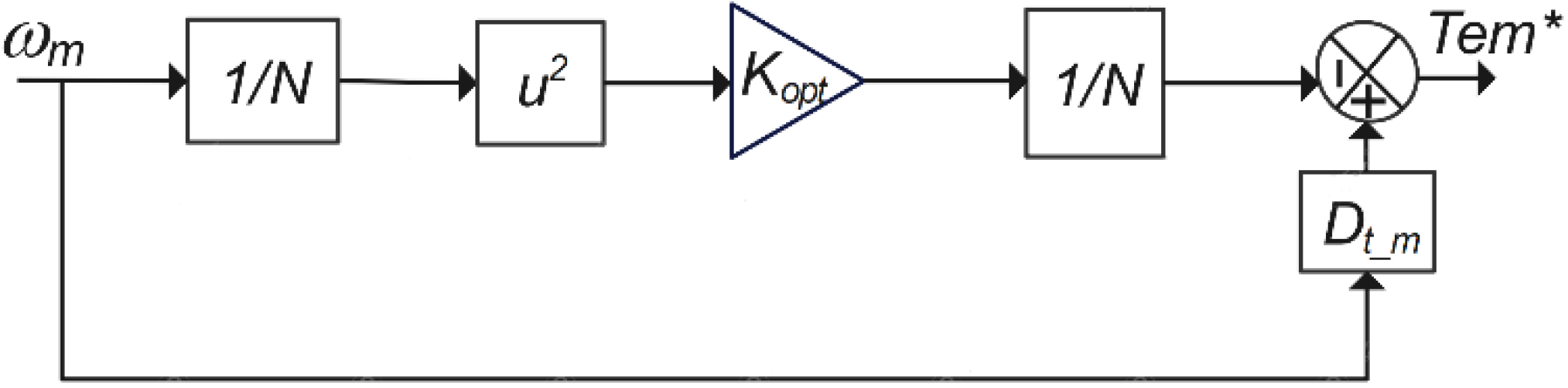
The response time, stability, and durability of control systems are very significant. At variable wind speeds, the response time of the WECS to this variation is expected to be rapid. To enhance the performance of RSC control, the MPPT control strategy was added to the RSC in addition to the PI controller. The reference torque (Tem*) value was produced using the MPPT controller block shown in Figure 7. It was aimed to obtain more appropriate results by calculating the reference torque with the MPPT controller. The proposed PI controller with MPPT applied to the RSC is shown in Figure 8.
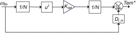
Figure 7.
MPPT controller applied to the rotor-side converter.
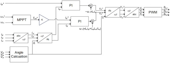
Figure 8.
Proposed controller of rotor side converter.
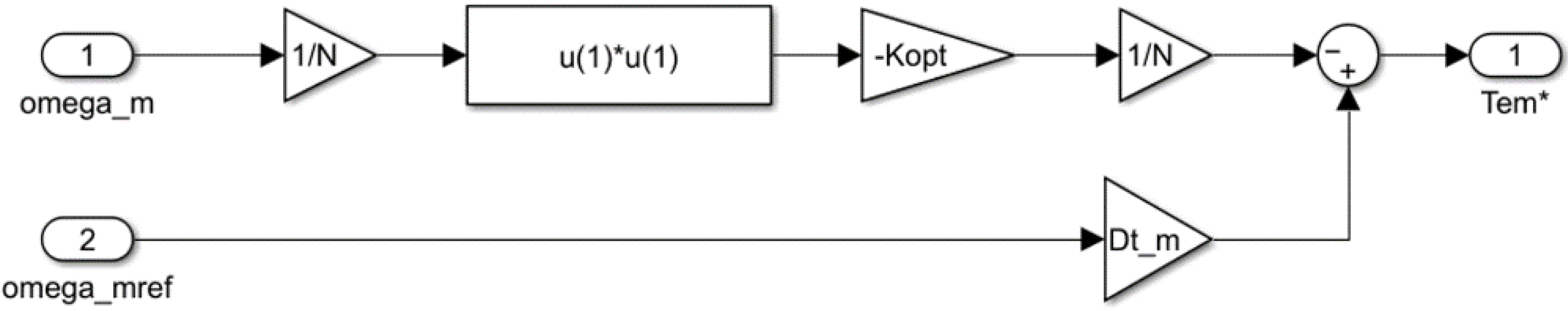
The main purpose of adding an MPPT controller to the RSC is to improve the response time of the WECS, electromagnetic torque, compatibility of the generated power with the power curve, and grid current by producing a more accurate Tem* compared with the PI controller. In the MPPT controller, the reference torque value is produced by using the angular velocity and reference angular velocity values of the DFIG. The MPPT controller designed in the Matlab/Simulink environment is shown in Figure 9.
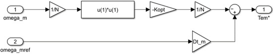
Figure 9.
MPPT controller in Simulink environment.
Here, Dt_m is the damping constant, N is the gearbox ratio, and Kopt is the optimization constant. Kopt can be stated as follows:
5. Simulation Setup
While analyzing the WECS using Matlab/Simulink, the wind speed data of the Edremit/Balikesir region in Turkey were used as the wind speed profile. The wind energy potential report published by the Ministry of Energy and Natural Resources of the Republic of Turkey in the Edremit/Balikesir region was examined. According to the report, it was observed that the transmission voltage is 154 kV in this region and the most compatible generator model for the region is the Nordex N90/2.5 MW. The WECS was designed according to setup criteria such as using real wind profile and using real parameters of the turbine model to obtain realistic and applicable results obtained from the system designed in Matlab/Simulink. Parameters of the DFIG designed in MATLAB/Simulink are listed in Table 1 and the grid-connected DFIG-based WECS designed in Matlab/Simulink is shown in Figure 10.

Table 1.
DFIG parameters.
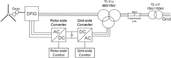
Figure 10.
Proposed grid-connected DFIG-based WECS system.
The power curve of a wind turbine expresses the relationship between the power generated by the turbine and the wind speed. Power curve aids in performance monitoring of the turbines. The power curve of the DFIG used in this study is illustrated in Figure 11. As seen in the power curve, the generator produces 2.5 MW rated power at its rated speed of 12 m/s. While the designed system is analyzed at variable wind speed, the power generated from DFIG should be compatible with the data in the power curve graphic shown in Figure 11. The simulation results at the real variable wind speed profile of the system will be given in the following section.
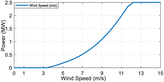
Figure 11.
Power curve of the DFIG.
6. Simulation Results
To increase the validity and applicability of the results of the present study, the real wind speed data of the Edremit/Balıkesir region, which has a wind potential that is the highest in Turkey, was used as the reference wind speed. The lookup table block in Matlab/Simulink is used to apply the real wind speed profile to the WECS as the wind speed value.
Firstly, the grid-connected WECS was designed with a conventional PI controller implemented to both rotor and grid side converters. Then, the MPPT controller was added to the rotor side converter to enhance the response time of the system and to match the generated power to the power curve of DFIG used in this study. WECS was tested at the real wind speed profile. The generated power, DC bus voltage, grid current, and response time parameters of the system were obtained. The results obtained from the conventional PI controller and proposed PI controller with MPPT were compared. In this section, the comparison of test results is discussed in detail.
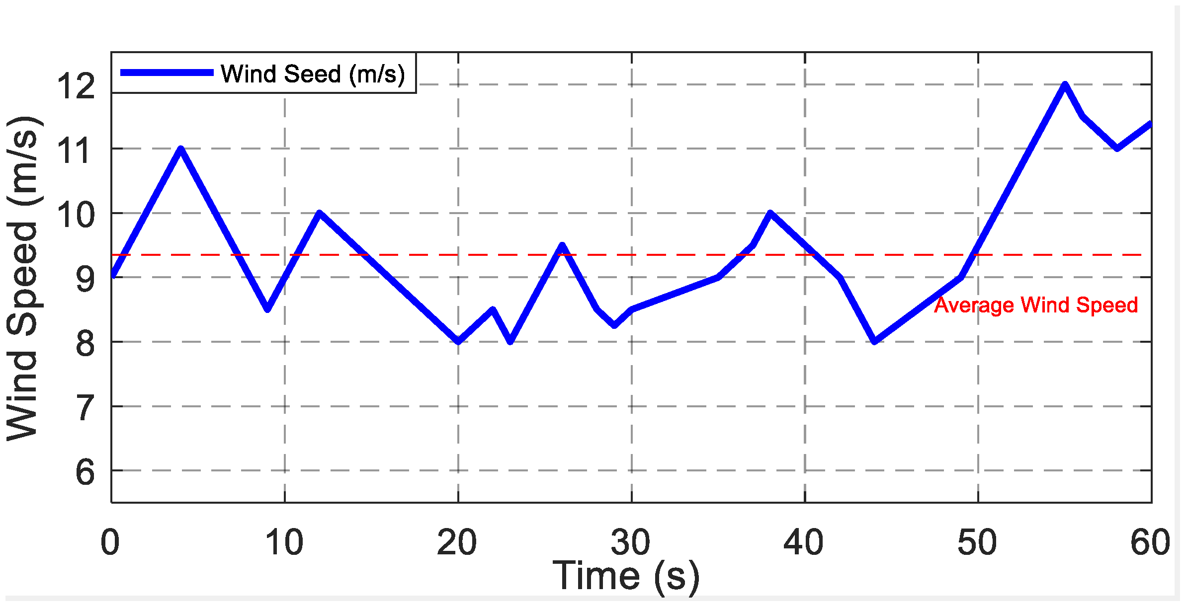
The real wind speed profile, measured on 12 January, at 09.00 a.m. at the Edremit/Balikesir region of Turkey, is illustrated in Figure 12. The average speed is 9.4 m/s in this speed profile.
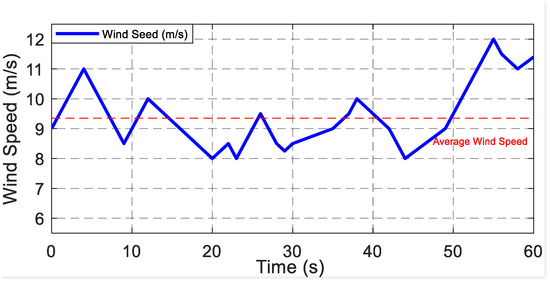
Figure 12.
The real wind speed profile (9.40 m/s average speed).
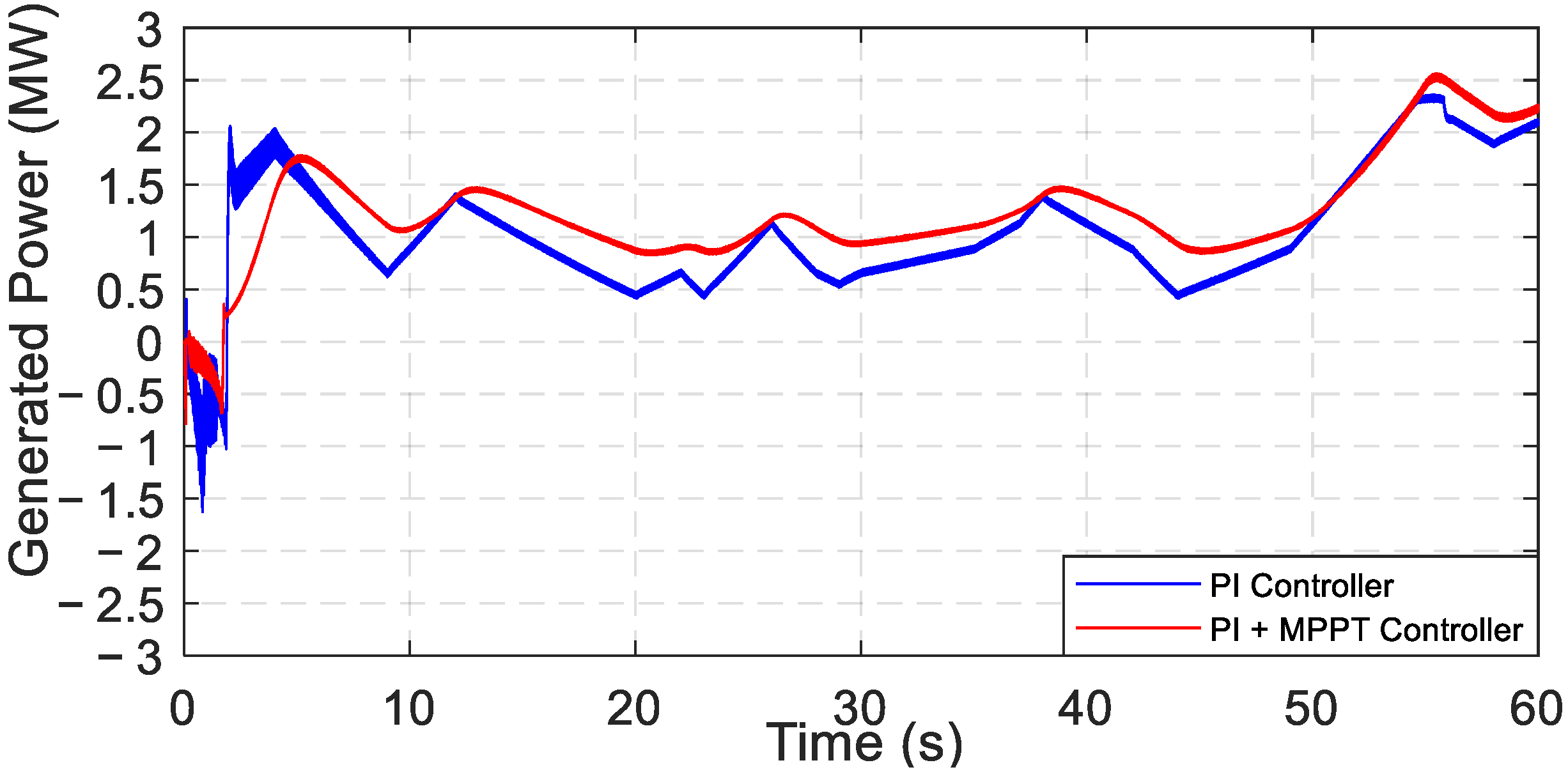
The generated active power graphics at this speed profile for both PI controller and PI with MPPT controller are shown in Figure 13.

Figure 13.
Generated power of the DFIG.
As seen from the figure, the doubly fed induction machine (DFIM) operates in motor mode in the initial condition of the test. The system with a conventional PI controller consumes more power in motor operating mode than the proposed PI+MPPT controller. While the PI-controlled system consumes a maximum of 1.6 MW power, the proposed PI+MPPT-controlled system consumes a maximum of 0.7 MW power. Then, both systems start to generate power. When the generated power according to the wind speed is compared for both controllers, it was observed that the generated power of the WECS with MPPT controller is fully compatible with the power curve of the DFIG. With respect to the PI+MPPT controller, the desired power value according to the power curve was generated at variable wind speed. According to the power curve of the DFIG, the system should generate 2.5 MW of power at the rated 12 m/s wind speed. By means of the proposed PI+MPPT controller, 2.5 MW rated power was generated, whereas 2.35 MW power was generated using a conventional PI controller. Moreover, a smoother power curve was obtained with the proposed method. It is clearly seen that the proposed control method gives better results than the conventional PI-controlled system.
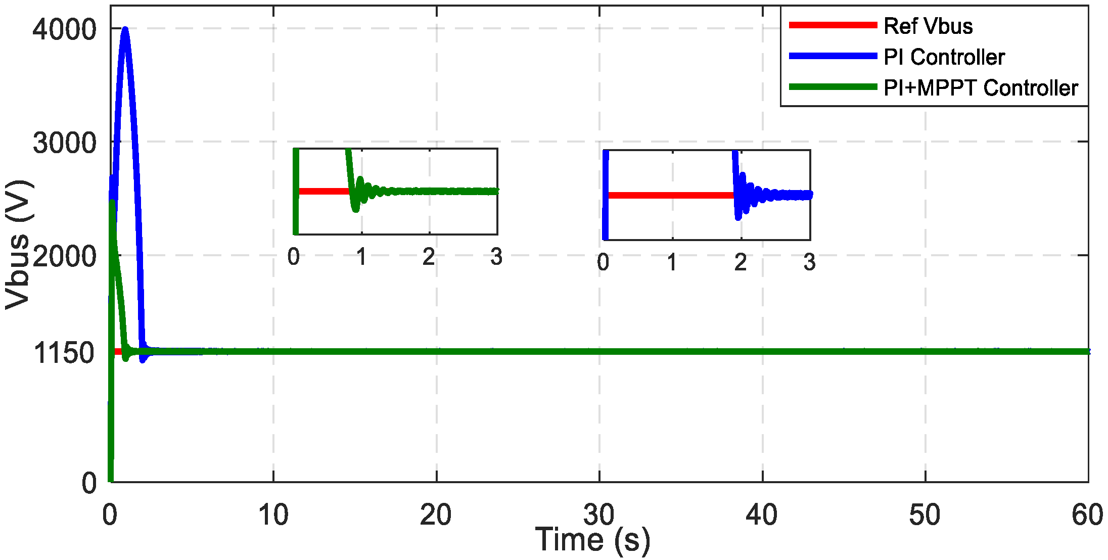
The designed system was also analyzed in terms of DC bus voltages. A DC bus voltage graphic of the designed system for both conventional PI controller and proposed PI+MPPT controller at variable wind speed are given in Figure 14.
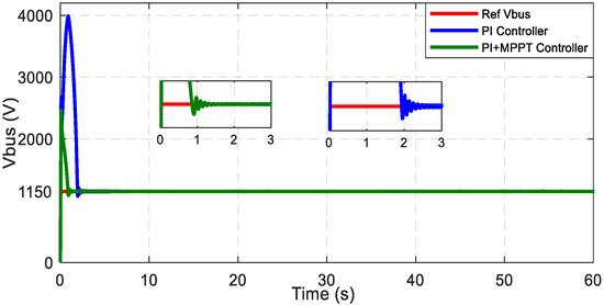
Figure 14.
DC bus voltages of WECS.
The reference DC bus voltage of the designed system is 1150 V. The PI-controlled system reached the reference DC bus voltage in 1.93 s, and it became stable in 2.4 s. Meanwhile, the PI+MPPT-controlled system reached the reference DC bus voltage in 0.80 s, and it became stable in 1.1 s. The voltage overshoot of the PI controller is quite large compared with the PI+MPPT controller. It is observed that the system using MPPT control reaches the reference 1150 V DC bus voltage faster with a lower overshoot. In terms of the security of the WECS, the proposed PI+MPPT controller provides more applicable and proper results. In this paper, generated power, response time, electromagnetic torque, and grid side currents were mainly discussed. This overshoot can be prevented with high voltage protection elements. In the literature, control systems based on artificial neural networks with MPPT angle control and using the direct power control technique are presented to overcome the response time and robustness problems of WECS [7,8,15]. When compared with these studies, the proposed PI+MPPT DFIG-based WECS follows the reference DC bus voltage with a faster response time at real variable wind speeds. In addition, the generated power of the WECS is more compatible with the power curve of the DFIG.
Moreover, the proposed system was analyzed from the viewpoint of grid 3-phase currents. The grid current graphics at the real wind speed profile given in Figure 12 for the conventional PI controller and proposed PI+MPPT controller are expressed in Figure 15 and Figure 16, respectively.
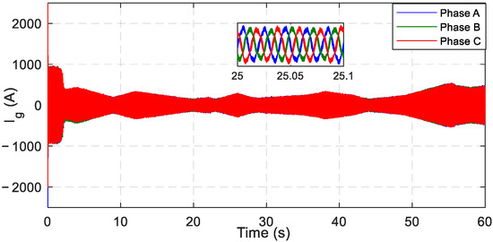
Figure 15.
Grid currents of WECS with PI controller.

Figure 16.
Grid currents of WECS with the proposed controller.
As seen from the current figures, phase currents of the PI-controlled system are 95 A higher than the proposed PI+MPPT-controlled system in the initial condition. According to the results, the response time of the PI+MPPT-controlled WECS is better than the response time of the PI-controlled WECS according to the change of wind speed. Smoother sinusoidal grid currents are obtained with the proposed PI+MPPT controller than the conventional PI controller. By examining the grid currents, it was shown that the response time of the PI+MPPT controlled system is better than the PI controlled system under the variable wind speeds.
Moreover, the proposed system was analyzed from the viewpoint of electromagnetic torque (Tem). The electromagnetic torque (Tem) graphic under the speed profile given in Figure 12 for both the PI controller and the PI+MPPT controller are shown in Figure 17.
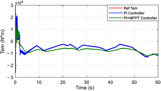
Figure 17.
Electromagnetic torque (Tem) of the DFIG.
Tem of the DFIG reached the reference torque faster with the help of the PI+MPPT controller when compared with the conventional PI controller. The reference torque value was followed successfully with the PI+MPPT controller. Moreover, a smoother Tem curve is obtained with the proposed method. The smoothness of the electromagnetic torque graph is important for the applicability of the proposed controller. By examining the Tem, it was shown that the response time of the PI+MPPT controlled system is better than the PI controlled system under the variable wind speeds.
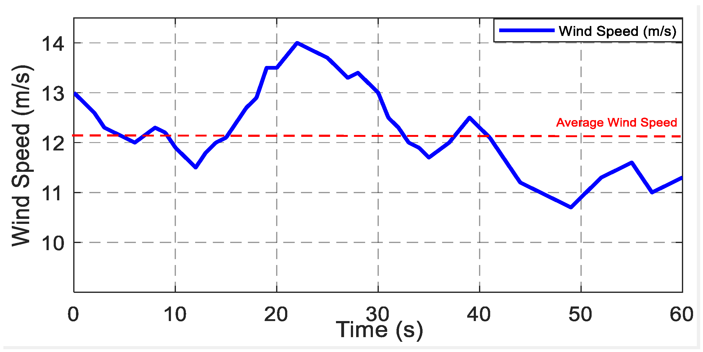
The proposed system was also tested under the rated speed of the DFIG used in this study. The real wind speed profile, measured on 20 March, at 12.30 p.m. at the Edremit/Balikesir region of Turkey, is illustrated in Figure 18. The average speed is 12.15 m/s in this speed profile.
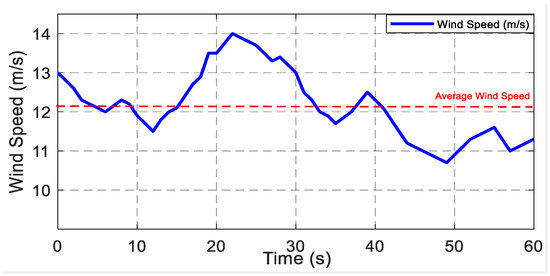
Figure 18.
The real wind speed profile (12.15 m/s average speed).
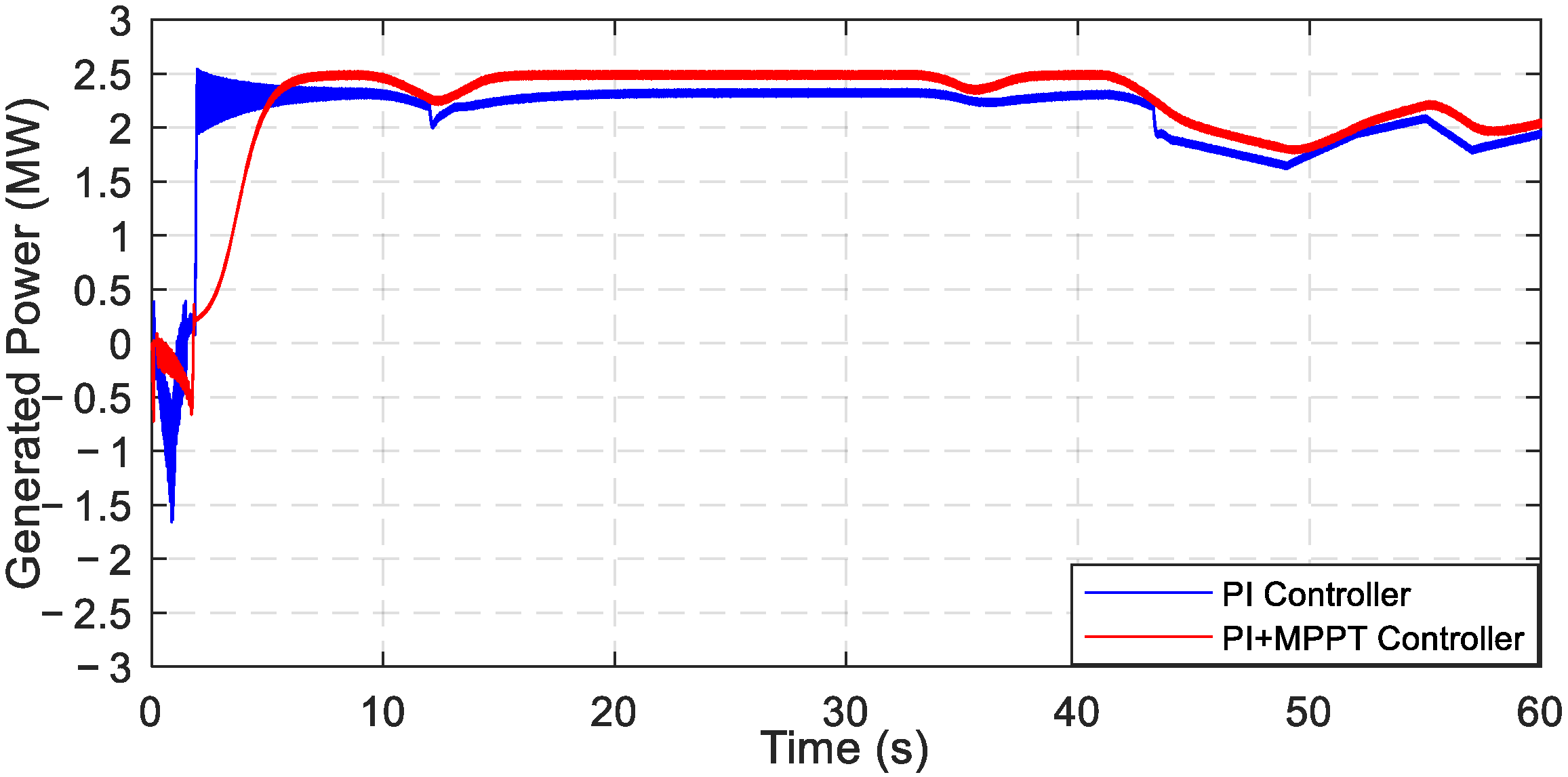
The generated active power graphics at this speed profile for both the PI controller and the PI+MPPT controller are shown in Figure 19.
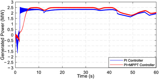
Figure 19.
Generated power of the DFIG.
The system with the conventional PI controller consumes more power in motor operating mode than the proposed PI+MPPT controller. While the PI-controlled system consumes a maximum of 1.7 MW power, the proposed PI+MPPT controlled system consumes a maximum of 0.75 MW power. Then, both systems started to generate power. When the generated power according to the wind speed is compared for both controllers, it was observed that the generated power of the WECS with MPPT controller is fully compatible with the power curve of the DFIG. With respect to the PI+MPPT controller, the desired power value according to the power curve was generated at variable wind speed. According to the DFIG power curve, the system should generate a constant 2.5 MW power at 12 m/s wind speed and higher wind speeds. By means of the proposed PI+MPPT controller, 2.5 MW rated power was generated, whereas 2.35 MW power was generated using the conventional PI controller at 12 m/s wind speed and higher wind speeds. Moreover, a smoother power curve is obtained with the proposed method. It is clearly seen that the proposed control method gives better results than the conventional PI-controlled system.
Furthermore, the designed system was analyzed in terms of DC bus voltages. The DC bus voltage graphic of the designed system for both conventional PI controller and proposed PI+MPPT controller at variable wind speed are illustrated in Figure 20.
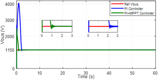
Figure 20.
DC bus voltage of WECS.
The reference DC bus voltage of the designed system is 1150 V. The PI-controlled system reached the reference DC bus voltage in 2.15 s. Then, it becomes stable in 2.4 s. Moreover, the PI+MPPT-controlled system reached the DC bus voltage in 0.86 s, and it becomes stable in 1.1 s. The voltage overshoot of the PI controller is quite large compared with the PI+MPPT controller. In this paper, generated power, response time, electromagnetic torque, and grid side currents were mainly discussed. This overshoot can be prevented with high voltage protection elements. It is observed that the system using MPPT control reaches the reference 1150 V DC bus voltage faster with a lower overshoot. In terms of the security of the WECS, the proposed PI+MPPT controller provides more applicable and proper results. It can be seen that the designed DFIG-based WECS at real variable wind speed follows the reference DC bus voltage with a fast response time.
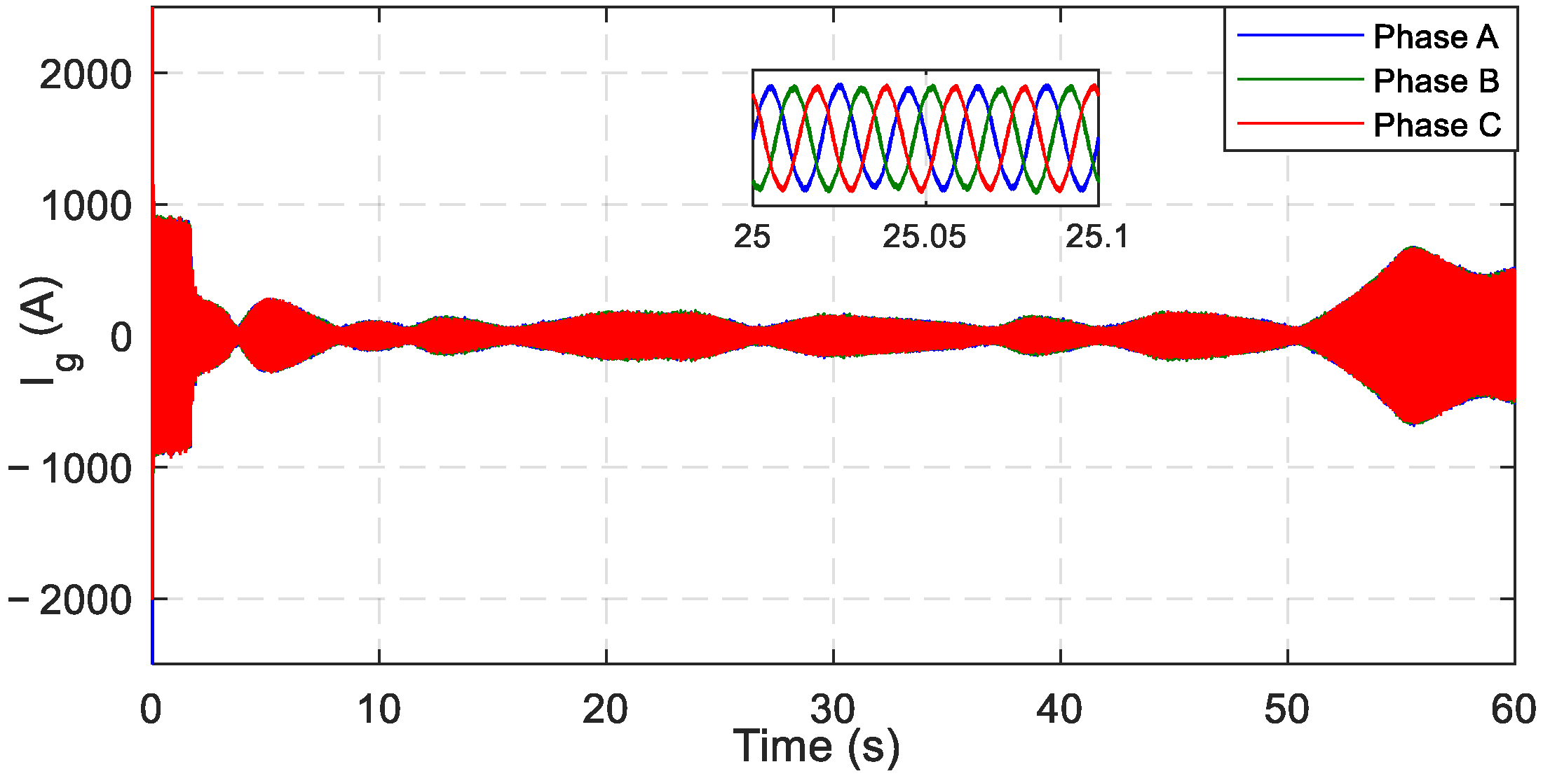
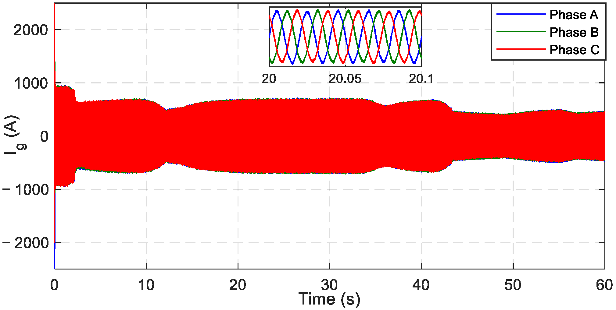
Moreover, the proposed system was analyzed from the viewpoint of grid 3-phase currents. The grid current graphics at the real wind speed profile given in Figure 18 for conventional PI controller and proposed PI+MPPT controller are expressed in Figure 21 and Figure 22, respectively.
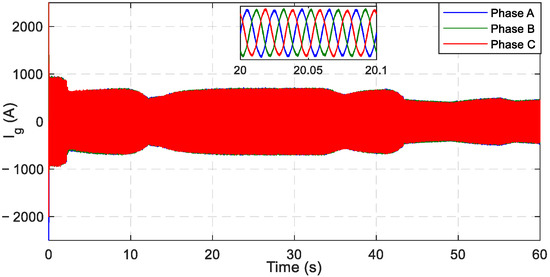
Figure 21.
Grid currents of WECS with PI controller.
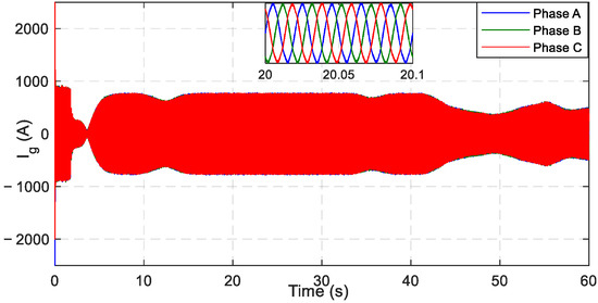
Figure 22.
Grid currents of WECS with the proposed controller.
As seen from the current figures, phase currents of the PI-controlled system are 145 A higher than the proposed PI+MPPT-controlled system in the initial condition. According to the graphs, the response time of the PI+MPPT controlled WECS is better than the response time of the PI-controlled WECS according to the change of wind speed. By examining the grid currents, it was shown that the response time of the PI+MPPT controlled WECS is better than the PI-controlled system under the variable wind speeds.
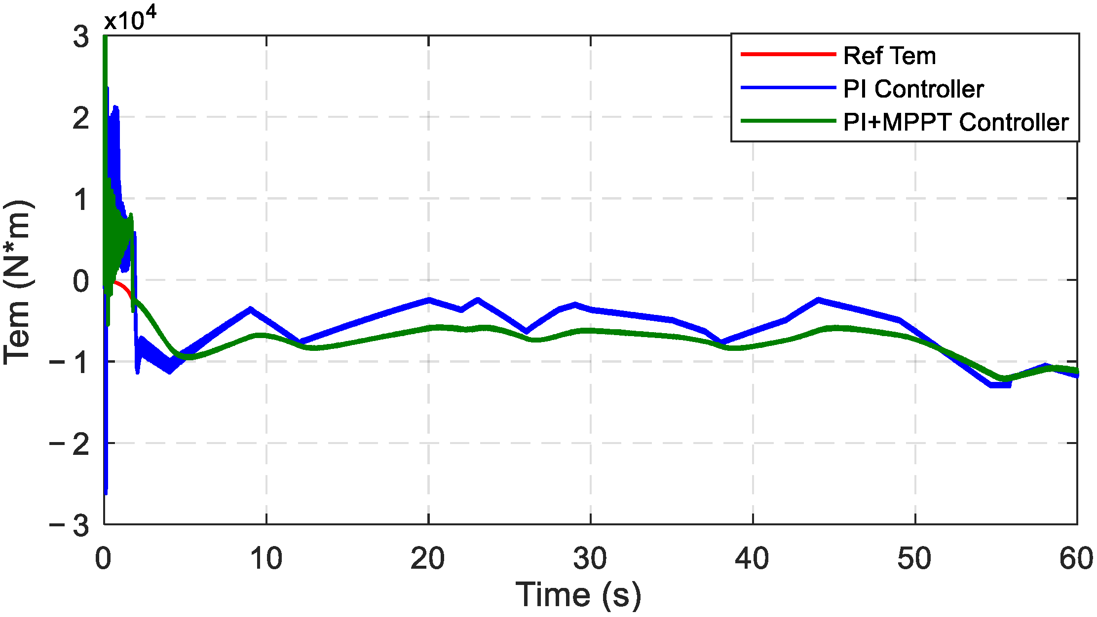
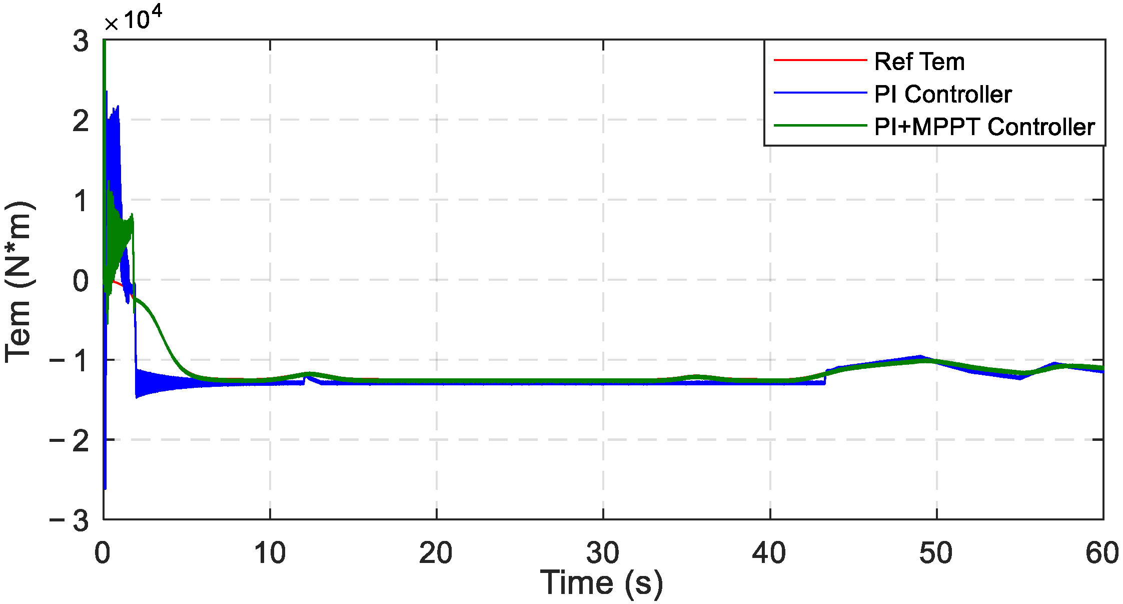
Additionally, the proposed system was analyzed in terms of electromagnetic torque (Tem). The electromagnetic torque (Tem) graphic under the speed profile given in Figure 18 for both the PI controller and PI+MPPT controller are shown in Figure 23.

Figure 23.
Electromagnetic torque (Tem) of DFIG.
The Tem of the DFIG reached the reference torque faster with the help of the PI+MPPT controller when compared with the conventional PI controller. The reference torque value was followed successfully with the PI+MPPT controller. Moreover, a smoother Tem curve is obtained with the proposed method. The smoothness of the electromagnetic torque graph is important for the applicability of the proposed controller. By examining the Tem, it was shown that the response time of the PI+MPPT-controlled WECS is better than the PI-controlled WECS under the variable wind speeds.
To make the simulation results shown in the graphics more understandable, the comparison of the test results at 20 s is given in Table 2. As previously mentioned, it is seen that the PI+MPPT controller gives more applicable and better results in terms of convergence time of the DC bus voltage, full compatibility of the generated power with the power curve, and higher electromagnetic torque.
Table 2.
Comparison table (at 20 s).
7. Conclusions
This paper presents the design and simulation of grid-connected DFIG-based WECS for the Edremit/Balikesir region of Turkey. The proposed system was tested at real variable wind speeds by using Matlab/Simulink. Firstly, a conventional PI controller was applied to both rotor side and grid side converters to produce the targeted power value with fast response time at variable wind speeds. Then, an MPPT controller was added to the RSC to achieve the generated power compatibility with the power curve and to improve the response time of the WECS. The designed system was analyzed at an average of 9.40 m/s and 12.15 m/s real measured variable wind speed profiles. Generated power, dc bus voltage, grid currents, electromagnetic torque, and response time results were obtained from the simulations. The results obtained from the conventional PI controller and from the proposed PI+MPPT controller were compared. The results of the proposed control method were also compared with the results of the related studies presented in the literature. The test and comparison results proved that adding an MPPT controller to the RSC of the DFIG improves the response time and produces active power that is fully compatible with the power curve of the DFIG. The results illustrated that the proposed PI+MPPT controller is applicable, effective, and reliable for grid-connected DFIG WECS at variable wind speed conditions.
Author Contributions
Conceptualization, E.B. and M.D.Y.; methodology, E.B. and M.D.Y.; software, E.B. and M.D.Y.; validation, E.B. and M.D.Y.; writing—original draft preparation, E.B. and M.D.Y.; writing—revising, E.B. and M.D.Y.; writing—reviewing, E.B. and M.D.Y.; supervision, E.B. All authors have read and agreed to the published version of the manuscript.
Funding
This research received no external funding.
Data Availability Statement
Not applicable.
Acknowledgments
The real measured wind speed data used in the present study were obtained from the Turkish State Meteorological Service.
Conflicts of Interest
The authors declare no conflict of interest.
References
- Fadaeinedjad, R.; Moallem, M.; Moschopoulos, G. Simulation of a wind turbine with doubly fed induction generator by FAST and Simulink. IEEE Trans. Energy Convers. 2008, 23, 690–700. [Google Scholar] [CrossRef]
- Patel, R.; Hafiz, F.; Swain, A.; Ukil, A. Nonlinear rotor side converter control of DFIG based wind energy system. Electr. Power Syst. Res. 2021, 198, 107358. [Google Scholar] [CrossRef]
- Jadhav, H.T.; Roy, R. A comprehensive review on the grid integration of doubly fed induction generator. Int. J. Electr. Power Energy Syst. 2013, 49, 8–18. [Google Scholar] [CrossRef]
- Pena, R.; Cardenas, R.; Asher, G. Overview of control systems for the operation of DFIGs in wind energy applications. IECON Proc. Ind. Electron. Conf. 2013, 60, 88–95. [Google Scholar] [CrossRef]
- Mousa, H.H.H.; Youssef, A.-R.; Mohamed, E.E.M. State of the art perturb and observe MPPT algorithms based wind energy conversion systems: A technology review. Int. J. Electr. Power Energy Syst. 2021, 126, 106598. [Google Scholar] [CrossRef]
- Pande, J.; Nasikkar, P.; Kotecha, K.; Varadarajan, V. A Review of Maximum Power Point Tracking Algorithms for Wind Energy Conversion Systems. J. Mar. Sci. Eng. 2021, 9, 1187. [Google Scholar] [CrossRef]
- Bossoufi, B.; Aroussi, H.A.; Boderbala, M. Direct Power Control of Wind Power Systems based on DFIG-Generator (WECS). In Proceedings of the 2020 12th International Conference on Electronics, Computers and Artificial Intelligence (ECAI), Bucharest, Romania, 25–27 June 2020; Volume 2, pp. 1–6. [Google Scholar] [CrossRef]
- Chhipa, A.A.; Kumar, V.; Joshi, R.R.; Chakrabarti, P.; Jasinski, M.; Burgio, A.; Leonowicz, Z.; Jasinska, E.; Soni, R.; Chakrabarti, T. Adaptive Neuro-Fuzzy Inference System-Based Maximum Power Tracking Controller for Variable Speed WECS. Energies 2021, 14, 6275. [Google Scholar] [CrossRef]
- Mahvash, H.; Taher, S.A.; Rahimi, M.; Shahidehpour, M. Enhancement of DFIG performance at high wind speed using fractional order PI controller in pitch compensation loop. Int. J. Electr. Power Energy Syst. 2019, 104, 259–268. [Google Scholar] [CrossRef]
- Zribi, M.; Alrifai, M.; Rayan, M. Sliding Mode Control of a Variable- Speed Wind Energy Conversion System Using a Squirrel Cage Induction Generator. Energies 2017, 10, 604. [Google Scholar] [CrossRef] [Green Version]
- Mehdi, H.; Farzad, R.S. Analysis and detection of a wind system failure in a micro-grid. J. Renew. Sustain. Energy 2016, 8, 043302. [Google Scholar] [CrossRef]
- Hu, L.; Xue, F.; Qin, Z.; Shi, J.; Qiao, W.; Yang, W.; Yang, T. Sliding mode extremum seeking control based on improved invasive weed optimization for MPPT in wind energy conversion system. Appl. Energy 2019, 248, 567–575. [Google Scholar] [CrossRef]
- Yasmine, I.; Chakib, E.B.; Badre, B. Improved Performance of DFIG-generators for Wind Turbines Variable-speed. Int. J. Power Electron. Drive Syst. 2018, 9, 1875. [Google Scholar] [CrossRef]
- Saravanakumar, R.; Jena, D. Validation of an integral sliding mode control for optimal control of a three blade variable speed variable pitch wind turbine. Int. J. Electr. Power Energy Syst. 2015, 69, 421–429. [Google Scholar] [CrossRef]
- Dahbi, A.; Nait-Said, N.; Nait-Said, M.S. A novel combined MPPT-pitch angle control for wide range variable speed wind turbine based on neural network. Int. J. Hydrogen Energy 2016, 41, 9427–9442. [Google Scholar] [CrossRef]
- Karakasis, N.; Tsioumas, E.; Jabbour, N.; Bazzi, A.M.; Mademlis, C. Optimal Efficiency Control in a Wind System With Doubly Fed Induction Generator. IEEE Trans. Power Electr. 2019, 34, 356–368. [Google Scholar] [CrossRef]
- Benzouaoui, A.; Khouidmi, H.; Bessedik, B. Parallel model predictive direct power control of DFIG for wind energy conversion. Int. J. Electr. Power Energy Syst. 2021, 125, 106453. [Google Scholar] [CrossRef]
- Zhang, Y.; Jiao, J.; Xu, D.; Jiang, D.; Wang, Z.; Tong, C. Model predictive direct power control of doubly fed induction generators under balanced and unbalanced network conditions. IEEE Trans. Ind. Appl. 2020, 56, 771–786. [Google Scholar] [CrossRef]
- Naik, K.A.; Gupta, C.P.; Fernandez, E. Design and implementation of interval type-2 fuzzy logic-PI based adaptive controller for DFIG based wind energy system. Int. J. Electr. Power Energy Syst. 2020, 115, 105468. [Google Scholar] [CrossRef]
- Bekiroglu, E.; Yazar, M.D. Analysis of Grid Connected Wind Power System. In Proceedings of the 2019 8th International Conference on Renewable Energy Research and Applications (ICRERA), Brasov, Romania, 3–6 November 2019; pp. 869–873. [Google Scholar] [CrossRef]
- Ananth, N.D.V.; Kumar, G.V.N. Tip speed ratio based MPPT algorithm and improved field oriented control for extracting optimal real power and independent reactive power control for grid connected doubly fed induction generator. Int. J. Electr. Comput. Eng. 2016, 6, 1319. [Google Scholar]
- Abad, G.; Iwanski, G. Properties and Control of a Doubly Fed Induction Machine. Power Electronics for Renewable Energy Systems. Transp. Ind. Appl. 2014, 18, 270–318. [Google Scholar] [CrossRef]
- Blaabjerg, F.; Iov, F.; Chen, Z.; Ma, K. Power electronics and controls for wind turbine systems. In Proceedings of the 2010 IEEE International Energy Conference, Manama, Bahrain, 18–22 December 2010; pp. 333–344. [Google Scholar] [CrossRef] [Green Version]
- Muljadi, E. Pitch-controlled variable-speed wind turbine generation. IEEE Trans. Ind. Appl. 2001, 37, 240–246. [Google Scholar] [CrossRef] [Green Version]
- Grauers, A. Efficiency of three wind energy generator systems. IEEE Trans. Energy Convers. 1996, 11, 650–657. [Google Scholar] [CrossRef] [Green Version]
- Ko, H.S.; Yoon, G.G.; Kyung, N.H.; Hong, W.P. Modeling and control of DFIG-based variable-speed wind-turbine. Electr. Power Syst. Res. 2008, 78, 1841–1849. [Google Scholar] [CrossRef]
- Abad, G.; Lopez, J.; Rodriguez, M.; Marroyo, L.; Iwanski, G. Doubly Fed Induction Machine: Modeling and Control for Wind Energy Generation Applications; Wiley-IEEE: Hoboken, NJ, USA, 2011; IEEE Press Series on Power Engineering. [Google Scholar]
- Chowdhury, B.H.; Chellapilla, S. Double-fed induction generator control for variable speed wind power generation. Electr. Power Syst. Res. 2006, 76, 786–800. [Google Scholar] [CrossRef]
- Colak, I.; Hossain, E.; Bayindir, R.; Hossain, J. Design a grid tie inverter for PMSG wind turbine using FPGA & DSP builder. In Proceedings of the 2016 IEEE International Power Electronics and Motion Control Conference (PEMC), Varna, Bulgaria, 25–28 September 2016; pp. 372–377. [Google Scholar] [CrossRef]
- Eltamaly, A.M.; Farh, H.M. Maximum power extraction from wind energy system based on fuzzy logic control. Electr. Power Syst. Res. 2013, 97, 144–150. [Google Scholar] [CrossRef]
- Mohammadi, J.; Vaez-Zadeh, S.; Ebrahimzadeh, E.; Blaabjerg, F. Combined control method for grid-side converter of doubly fed induction generatorbased wind energy conversion systems. IET Renew. Power Gener. 2018, 12, 943–952. [Google Scholar] [CrossRef]
- Muller, S.; Deicke, M.; de Doncker, R.W. Doubly Fed Induction Generator Systems. IEEE Ind. Appl. 2002, 34, 26–33. [Google Scholar] [CrossRef]
- Pura, P.; Iwański, G. Rotor Current Feedback Based Direct Power Control of a Doubly Fed Induction Generator Operating with Unbalanced Grid. Energies 2021, 14, 3289. [Google Scholar] [CrossRef]
- Amrane, F.; Chaiba, A.; Francois, B.; Babes, B. Real time implementation of grid-connection control using robust PLL for WECS in variable speed DFIG-based on HCC. In Proceedings of the 2017 5th International Conference on Electrical Engineering—Boumerdes (ICEE-B), Boumerdes, Algeria, 29–31 October 2017; pp. 1–5. [Google Scholar] [CrossRef]
- Hu, J.; Xu, H.; He, Y. Coordinated Control of DFIG’s RSC and GSC Under Generalized Unbalanced and Distorted Grid Voltage Conditions. IEEE Trans. Ind. Electr. 2013, 60, 2808–2819. [Google Scholar] [CrossRef]
- Kou, P.; Liang, D.; Li, J.; Gao, L.; Ze, Q. Finite-Control-Set Model Predictive Control for DFIG Wind Turbines. IEEE Trans. Autom. Sci. Eng. 2018, 15, 1004–1013. [Google Scholar] [CrossRef]
- Chang, Y.; Hu, J.; Tang, W.; Song, G. Fault Current Analysis of Type-3 WTs Considering Sequential Switching of Internal Control and Protection Circuits in Multi Time Scales During LVRT. IEEE Trans. Power Syst. 2018, 33, 6894–6903. [Google Scholar] [CrossRef]
- Xiao, X.Y.; Yang, R.H.; Chen, X.Y.; Zheng, Z.X.; Li, C.S. Enhancing fault ride-through capability of DFIG with modified SMES-FCL and RSC control. IET Gener. Transm. Distrib. 2018, 12, 258–266. [Google Scholar] [CrossRef]


Publisher’s Note: MDPI stays neutral with regard to jurisdictional claims in published maps and institutional affiliations. |
© 2022 by the authors. Licensee MDPI, Basel, Switzerland. This article is an open access article distributed under the terms and conditions of the Creative Commons Attribution (CC BY) license (https://creativecommons.org/licenses/by/4.0/).