Abstract
The paper presents the development of a megavolt-class SF6-insulated radial switch. The switch is used as a crowbar in a MV Tesla-type generator to produce pulsed electric fields in very large volumes, for proof-of-concept experimentation of a novel non-invasive food processing technology. The main features of the switch include: (1) Using SF6 gas as the insulation gas; (2) a breakdown channel along the radial direction, rather than axial; (3) a compact configuration with its volume limited to 3.2 L. In order to achieve a ruggedized high voltage insulation as well as an enhanced operation safety, the following design techniques were applied: (1) Structures of the switch were well designed to minimize the local electric filed in the cathode triple junctions; (2) the grooves of surface of the insulators that enclose the switch were finely optimized to keep the surface flashover under control; (3) a prolate spheroid geometry of the high voltage electrode was adopted to achieve a better control of the gas breakdown. This paper describes in detail the design and the preliminary test of this switch.
1. Introduction
The closing switch is an essential component for most pulsed power systems, since it is not only related to the performance of the system but also relevant to its overall weight and size [1,2,3,4,5,6]. Due to its importance, a great effort has been undertaken to improve the main characteristics of the closing switch such as jitter, lifetime, operating voltage, and weight. Different types of switches have been developed, such as the single gas-gap switch [7,8], the trigatron switch [9,10,11], the V/N switch (voltage-division number) [12,13,14], the corona-triggered switch [15,16,17], and the radial switch [18,19].
Each kind of closing switch has its own advantages and disadvantages. For example, the single gas-gap switch can conduct a high current up to hundreds of kilo amperes (kA), but the repetition rate is limited and the jitter can be relatively large [7,8]. The trigatron switch, designed with a needle-like electrode placed in the center of the low-voltage (LV) electrode of the gas gap to initiate the breakdown, can partially solve the problem of jitter [9,10,11]. In order to increase the repetition rate and further lower the jitter of the single gas-gap switch, the V/N switch and the corona switch were developed, the former using the technology of the LC circuit (inductance and capacitor) to revert the voltage to realize trigger [12,13,14] and the latter using the technology of corona discharge to initiate and stabilize the discharge [15,16,17]. Both switches, working in a SF6 atmosphere, can reduce the jitter within a range of 5% [12,16] and can work at a voltage level of 1 MV.
Aside from these switches, some other types of switches which can operate at a voltage higher than 1 MV were also reported, such as the 2-MV self-triggered switch [20], the 2.4-MV annulus flat water switch [21], the 3-MV UV illumination switch [22], and the 3-MV multi-channel multi-stage reduced-model switch [23]. All these types of switches were designed with the discharge channel in the axial direction, which is also the direction of the energy transmission.
Switches with radial discharging channels are needed in some specific occasions. In ref. [18], the design criteria for such a switch was reported and a wide-band switch was designed and tested. The switch in ref. [18] was used in satellite communication mobile terminals, rather than in the pulsed power domain. Later, a higher power (10 kV, 40 kA) radial switch was reported in ref. [19], working with 24-atm H2 gas as the insulation media.
Even there are two types of radial switches reported, they just operate in a relatively low voltage level. There is no radial switch which operates at a voltage either in the hundred-kilo-volts class or in the MV class reported.
In this paper, a MV-class radial switch was designed for a Tesla-type pulsed power generator. Main features of the switch are as follows: (1) Having MV-class and radial working mode; (2) using only SF6 as the insulating gas (1 atm ≈ 105 Pa = 1 bar); (3) having a gas chamber as small as 3.2 L in volume; (4) enclosing the electrodes with reliably-insulated supporting insulators. Section 2 is devoted to the general considerations for the design of such a switch. Section 3 is devoted to calculating the operating parameters of the switch. Section 4 deals with numerical simulation of the electrical characteristics and further optimization. Section 5 presents the preliminary testing of this switch. The paper ends presenting a few conclusions.
2. General Consideration
2.1. General Considerations Related to the Tesla-Based System
Small-size switches have been previously implemented in Tesla-driven generators for producing very fast impulses of high power [24,25,26], but the present work is to develop a powerful pulsed electric field (PEF) system for proof-of-concept testing a novel and non-invasive food processing technique according to ref. [27]. Figure 1a shows the 3-D model of the Tesla-based generator, which comprises three parts: a Tesla transformer, a main switch, and a load. The Tesla transformer consists of a single-turned primary winding surrounding a multi-turned secondary one without using magnetic cores. The load consists of a parallel plate capacitor and a solenoid inductor. The global envelope of the generator is 1270 mm × 600 mm, which is compact and light via mechanical estimations. The Tesla transformer charges the capacitor to about 1 MV in ~2μs. Then the switch breaks down, resulting in a sinusoidal oscillation of the high voltage across the two plates of the capacitor. High electric field with high frequency between the two plates is then produced, which is going to be used for investigations of non-invasive food processing technique.
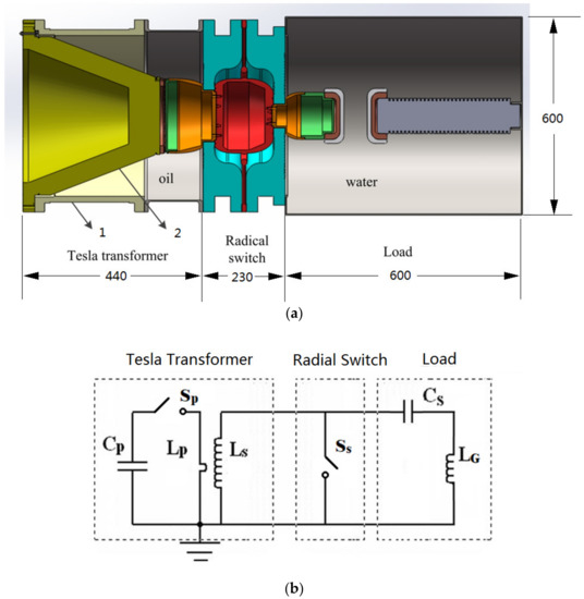
Figure 1.
3-D model (a) and equivalent circuit (b) of the Tesla transformer-driven system for PEF food processing. 1, 2—mechanical supports for primary and secondary windings; Cp, Cs—the primary and the secondary capacitors of the Tesla transformer (TT); Lp, Ls—the primary and the secondary inductors of TT; Sp, Ss—the primary and the (secondary) main switch of TT; LG—the grounding inductor of TT.
Figure 1b shows the equivalent circuit of the 1-MV Tesla-type generator. The main switch (Ss) is used to crowbar the Tesla transformer circuit separating it from the load, while the load is used to process food using the PEF generated by the secondary capacitor (Cs). An operating cycle of this generator can be described as follows: first, the primary capacitor (Cp) is charged followed by the primary switch (Sp) closure. During the Cp discharge, the output voltage from the transformer charges the secondary capacitor (Cs) to values close to 1 MV. When the voltage reaches a pre-established value, the main switch (crowbar) closes, generating fast oscillations through the LC load circuit while the PEF processes the food.
The values of Cp, Cs, charging time, inductance of the primary and secondary inductors of the Tesla transformer are optimized by circuit simulation, which is beyond the aim of this paper and will be introduced in another paper.
Since the Tesla transformer is coaxial and the main switch is used to crowbar the Tesla transformer secondary circuit, the switch must be designed having a radial, rather than axial geometry. In addition, this switch should be as compact and as light as possible, to allow the overall system to be compact and light.
2.2. General Considerations Related to the Switch Design
Figure 2 shows the generic design of the radial switch, in which the outer diameter of the main switch insulators is determined by the outer diameter of the Tesla transformer itself (490 mm), while the axial length can be adjusted as required. As the main switch needs to operate under a voltage approaching 1 MV, a high-pressure gas is chosen as a convenient insulation medium, which is finally fixed as SF6, as it requires about three times less pressure than N2 to achieve the same electric field breakdown stress [28]. The following characteristics are required to be observed during the switch design:
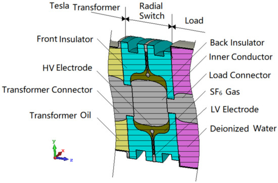
Figure 2.
3-D model of the radial main switch. HV electrode means the electrode mounted as part of the inner conductor of the generator and LV electrode means the grounded electrode.
- (1)
- The SF6 gas should breakdown electrically at a pre-determined voltage, i.e., no “misfires” are allowed;
- (2)
- The SF6 gas should be capable to maintaining insulation integrity up to a pre-determined voltage, i.e., no “pre-fires” are allowed;
- (3)
- The Front and Back Insulators should not allow electric flashover phenomena over their surfaces facing the gas chamber;
- (4)
- The oil–insulator surface of the Front Insulator should not allow surface flashover phenomena;
- (5)
- The water–insulator surface of the Back Insulator should not allow surface flashover phenomena;
- (6)
- The volume of the switch gas chamber should be made as small as possible.
3. Switch Parameters
The operating voltage of this switch is up to 1 MV. The gap separation and the gas pressure must be adjusted according to the Paschen Law [29] in order that the switch can work properly. Therefore, these two parameters need to be first determined.
The breakdown characteristics of SF6 under nanosecond impulses were thoroughly studied by H. J. Ruan and the conclusions were summarized in her Ph. D. thesis [28]. Two important characteristics are provided in ref. [28]: the breakdown field per atm of SF6 in a uniform electric field, i.e., 88.5 kV/(cm·atm), and the surface flashover electric field per atm of SF6, i.e., 73.5 kV/(cm·atm). Since a quasi-uniform electric field is expected to be generated between the switch electrodes, the above data are useful, and the operating parameters of the radial switch can therefore be established. In ref. [1], the following formula is suggested to calculate the breakdown voltage for common insulation gases, such as air, N2, H2, and SF6:
where Ub is in kV, pd is in cm·atm. Two sets of (Ub, p, d) are used for SF6 from ref. [28]. One is (120 kV, 2.7 atm, 0.5 cm); another is (88.5 kV, 1 atm, 1 cm). With these data, c0 and c are calculated to be 88.54 kV/(cm·atm) and −0.04 (kV/(cm·atm))0.5, respectively. So, Ub of SF6 in a uniform filed can be expressed as follows:
With (2), Table 1 lists few examples of gas pressure (p), gap distance (d), and breakdown field (Eb) as well as the flashover field (Ef) for a voltage of 1 MV applied between electrodes. It is worth mentioning that once the pressure is fixed, the electric field generated between the switch electrodes should be larger than Eb, to ensure the switch closes (“fires”) while the electric field produced along the two insulator surfaces inside the gas chamber should be smaller than Ef, to prevent any surface flashover phenomena.

Table 1.
The gap distance, breakdown, and surface flashover threshold of SF6 for 1 MV applied.
Based on Table 1, the dependences of the switch gap distance and of the breakdown field on SF6 pressure for a 1-MV voltage, are both presented in Figure 3a.
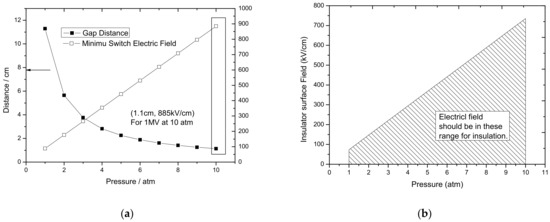
Figure 3.
The dependences of the gap distance and the electric breakdown field on SF6 pressure for 1 MV voltage (a) and the dependence of insulator surface field on SF6 pressure (b).
Theoretically, based on the Paschen Law, all the combinations of the pressure and the corresponding gap distance can result in a breakdown at 1-MV voltage. However, a low pressure would correspond to a too long gap and would correspondingly increase the switch resistance and self-inductance. In addition, the jitter would also increase. Therefore, the gas chamber pressure should be high, but it cannot be too high because it would produce large forces acting on the two insulators. In such cases, the insulators must be thick enough to withstand the forces. This means that the total size and the overall weight of such a switch would be unpractical. For the present design, the theoretical pressure was chosen to be around 10 atm and the corresponding switch gap distance was set as 12 mm. In this case, the electric field on the electrode surface should be larger than 885 kV/cm to ensure a breakdown. It is worth mentioning that if the finally-tested voltage is smaller than 1 MV, the pressure in the switch chamber can be increased moderately to realize such a high voltage.
The dependence of the electric field threshold on pressure for surface flashover is shown in Figure 3b. The electric field on the insulator surface should be smaller than the threshold value, and this is presented as the highlighted operational region. Once the operating pressure is fixed as 10 atm, the electric field on the insulator’s inner surface should be no greater than 735 kV/cm.
It is also worth mentioning that the insulator surface field should be as small as possible to realize a large design margin. If necessary, the gas pressure can be increased higher than 10 atm to realize the desired 1-MV voltage.
4. Optimization Techniques
After deciding the switch operating parameters, the design details should be optimized in order to meet the requirements listed in Section 2.2.
4.1. Global Field Distribution and Optimization Targets
Figure 4 presents the potential and the electric field distribution for the radial gas switch for the initial design. The LV electrode is designed as a sphere with a diameter of 16 mm, mounted perpendicular to the inner (central) HV conductor of the Tesla transformer. The HV electrode length along axis is 230 mm. The thickness for both insulators, inserted into the inner conductor is 35 mm, which is ascertained by mechanical simulation loaded with the largest pressure. Polyethylene (PE) is chosen as insulator material for the gas chamber with the dielectric constant (εr) of 2.2 while εr of the transformer oil is 2.3 and εr of the deionized water at the room temperature the system is operated is considered as 81. Figure 4a shows that the high voltage is concentrated along the inner surface area of the generator, while Figure 4b shows that the high electric field area is concentrated in the inner of the gas chamber, both results being expected.
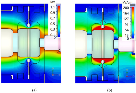
Figure 4.
Initial design of the radial SF6-insulated main switch. Overall potential distribution (a) and electric field distribution (b) for 1 MV applied.
Optimization techniques were next applied to all switch components, as follows:
- (1)
- For the HV and the LV surfaces of the two electrodes, the optimization target was to generate a uniform electric field and to ensure that breakdown of the SF6 will be possible in the range of pressure and voltage considered;
- (2)
- For the gas–insulator interface toward the Tesla transformer secondary winding filled with oil and for the gas–insulator interface toward the water-filled load, the optimization target was to prevent SF6-insulator surface flashover;
- (3)
- Same as (2) for both the oil–insulator and for the water–insulator interface;
- (4)
- For the gas chamber, the optimization target is not only to minimize the volume but also to reduce its axial length as much as possible.
It is noted that during simulation, the size of mesh is controlled smaller than one-third of the characteristic size of the grooves; the size of regions near cathode triple junctions (CTJ) is smaller than one-fifth of the critical size.
In order to assess the results obtained from the optimization effort, the corresponding electric field distributions along all six surfaces were analyzed after each cycle of optimization, as shown in Figure 5.
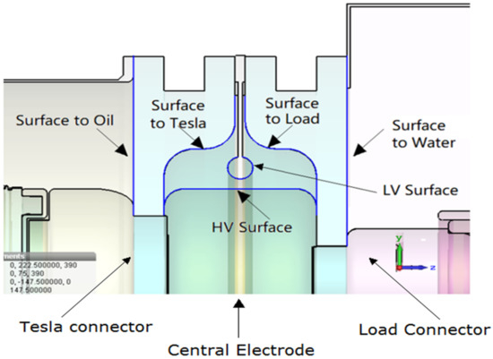
Figure 5.
Schematic of all surfaces and interfaces to optimize.
4.2. Optimization
Using the targets defined above and the electric field distribution of the initial design, a number of cycles of optimization have been undertaken. Figure 6 presents the final version of the switch design. The main changes include: (1) A “bulge”, having an outer diameter of 16 mm, is now implemented on the previously smooth surface of the inner (central) HV electrode; (2) the total axial length of the switch has been reduced to 210 mm; (3) the thickness of the two insulators inserted into the inner system conductor has been decreased to 30 mm, with a number of circular grooves being also implemented; (4) the outer surface of all the three components of the system inner conductor (i.e., the Tesla connector, the central electrode of switch and the load connector) has been modified by implementing an elliptical geometry; (5) the volume of the gas chamber has been substantially reduced (details are provided below).
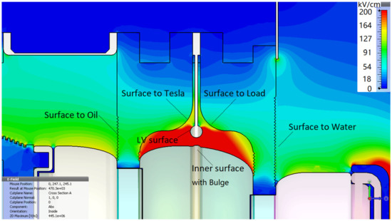
Figure 6.
Electric field distribution inside the final-version design of the radial switch.
In what follows, based on Figure 6, the new electric field distributions are presented and analyzed.
4.2.1. Electrode Surface
Figure 7 shows the electric field distributions along the surface of the HV and the LV electrodes. It is obvious that the two distributions are very similar, which means a non-uniform electric field is generated. This result is obtained because of implementation of the sphere-to-bulge geometry. From Figure 7, it is also seen that the maximum electric fields (Emax) on the HV and the LV electrode are as high as 1010 kV/cm, which is higher than the EBD of SF6 at 10 atm (850 kV/cm) and therefore the switch will be capable to fire once the voltage applied exceeds 1 MV.
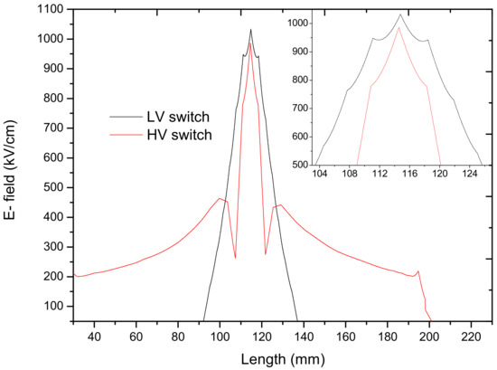
Figure 7.
Electric field distributions along the surface of the HV and LV electrodes for 12-mm gap.
4.2.2. Gas–Insulator Interfaces
Figure 8 shows the electric field distributions along the two gas–insulator interfaces. The data indicate that the electric field strength on these surfaces does not exceed 200 kV/cm, a value much smaller than the characteristic Ef for a SF6-insulator interface at 10 atm (735 kV/cm), which results in a large safe margin. So, it can be concluded that the gas chamber inner surfaces are safely designed in relation to any electric flashover phenomena. In addition, grooves are carved on the inner insulator surfaces. As shown in Figure 9, the grooves have a saw-tooth like geometry, with a pseudo-period of 4 mm and an upper and a down slope of 45°. The grooves have two functions: to reduce the electric field strength on the cathode triple junction (CTJ) area, as seen in Figure 10, and to generate ripples in the electric field distribution along a distance of about 80 mm near the HV electrode, as shown in Figure 8. Both characteristics considerably reduce the probability of surface flashover.
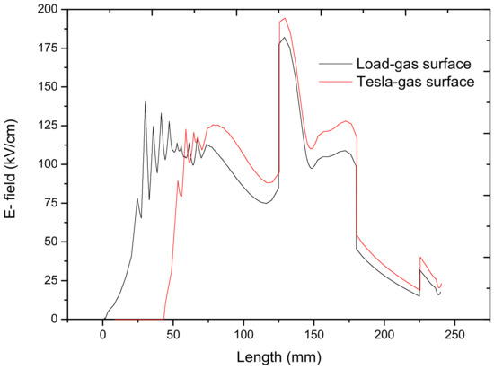
Figure 8.
Electric field distributions along the two gas–insulator interfaces.
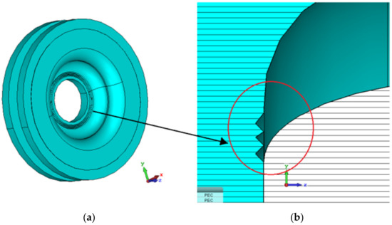
Figure 9.
Grooved insulator area (a) enlarged view (b).
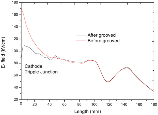
Figure 10.
Comparison of the electric field distributions on the insulator surface before and after implementing the grooves.
4.2.3. Insulator–Oil and Insulator–Water Interfaces
The field distribution on both the insulator–oil and the insulator–water interfaces are also optimized using the same “grooving” technique as described above. Figure 11 shows the 3-D design of a grooved insulator and the corresponding electric field distributions along the two insulators surface.
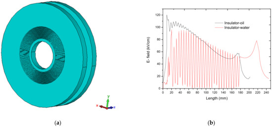
Figure 11.
Insulator–oil and insulator–water interfaces provided with grooves. (a) 3-D model (b) the corresponding electric field distributions.
As presented, on the insulator–oil surface, the maximum electric field Emax is only 120 kV/cm, a value considered to be safe [7]. To prove this assumption, a detailed analysis follows. In ref. [7], a coaxial line with an outer diameter (Do) of 250 mm and an inner diameter (Di) of 91.5 mm is considered, and a maximum voltage (Umax) of 660 kV is applied with the surface of the insulator being smooth. Using the simple formula:
the average field (Eav) for the system described in ref. [7] is estimated as 83 kV/cm and using an electrostatic software, the Emax on insulator surface is determined to be 125 kV/cm. For the coaxial line of the current generator, Do is 430 mm; Di is 190 mm; Umax is 1 MV. Therefore, using (3), Eav is estimated as 83 kV/cm and, using an electrostatic solver, Emax is obtained as 120 kV/cm. In addition, in the present design, the insulator surface is grooved, thus increasing the surface flashover path.
In the case of the insulator–water interface, the Emax does not exceed 100 kV/cm, which is also lower than values reported in ref. [30] and therefore is safe. A similar detailed analysis as presented above follows. In ref. [30], the coaxial water-filled line has the following parameters: Do is 380 mm, Di is 220 mm, Umax is 600 kV, Eav is estimated to be 75 kV/cm, and Emax is calculated as 130 kV/cm. In comparison, the present design of the coaxial line connecting the water-filled load has the following characteristics: Do is 500 mm, Di is 120 mm, Umax is 1 MV, Eav is therefore estimated to be 52 kV/cm, and Emax is simulated to be 100 kV/cm. Same conclusions as above apply.
4.2.4. The Gas Chamber
As already mentioned above, the gas chamber is expected to be as small as possible to decrease the overall size and limit the forces acting on insulators by the high-pressure gas. However, the switch chamber cannot be made too small, as the electric field strength on the inner insulator surface would become too large and will cause surface flashover. Therefore, a balance should be maintained between the volume of the gas chamber and the electric field distribution along the inner surface of the insulators. In the present design, a maximum electric field level of 180 kV/cm was chosen as the main parameter to be observed during design optimization. Figure 12 compares the gas chamber before and after optimization: the volume of the gas chamber decreased significantly from 8.3 L down to only 3.2 L.
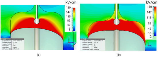
Figure 12.
The gas chamber before (a) and after (b) optimization. The gas volume reduced from 8.3 L (a) to only 3.2 L (b).
4.2.5. Connections to Tesla and Water Load
In addition to the four optimization techniques mentioned above, the geometry of the central HV electrode connectors with both the Tesla transformer and the water load must also be optimized, as presented in Figure 13.
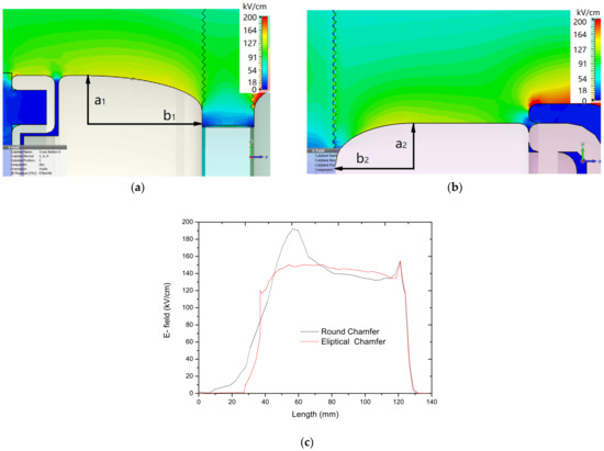
Figure 13.
The geometry of the connectors with Tesla (a) and with the water load (b); the corresponding electric field distribution on the surfaces of the load connector before and after optimization (c).
The technique employed uses a part of a spherical prolate shape, instead of the traditional spherical shaping method. By adjusting the semi-axis “a” and “b”, an optimum field enhancement factor (FEF) can be obtained. For example, for the connector toward Tesla, as presented in Figure 13a, if “a1” is set as 40 and “b1” is set as 80, the FEF is obtained as 1.17. As shown in Figure 13b, for this geometry and using an electrostatic solver, the Emax is calculated as 150 kV/cm as follows: first, using the formula:
E’av can be estimated as 128 kV/cm, where Do is 430 mm, Di is 190 mm, and Umax is 1 MV. f, the field enhancement factor (FEF), is simulated to be 1.17 for a spherical prolate shaped electrode, which is much smaller than that obtained by the simpler spherical shaping technique, for which the FEF is usually obtained with values between 1.3 and 1.5. A small value for the FEF not only reduces the breakdown probability of oil or water, but also decreases the Emax on the surfaces of the two corresponding insulators.
As a summary, the following characteristics of the switch optimization were successfully obtained:
- (1)
- For a voltage of 1 MV, the final electrode design generates an electric field up to 1010 kV/cm, which should produce the electrical breakdown of the pressurized gas;
- (2)
- For a safe and reliable operation, the electric field on the four surfaces of the gas chamber insulators is maintained at a relatively low value;
- (3)
- The two metallic connectors mounted on the central HV electrode have a relatively low FEF, which allows their safe operation under oil and water;
- (4)
- The volume of the gas chamber has been reduced to only 3.2 L.
5. Preliminary Testing
The preliminary tests were conducted, which shows that the voltage on the secondary winding, Us, of the Tesla transformer increases linearly as the pressure increases, which is just what is expected. However, Us is only 860 kV when the pressure of the switch is 10 atm, not equal to 1 MV as expected. There are probably two reasons.
First, the switch gap works in a pd range of 12 atm·cm (=1.2 cm × 10 atm), which belongs to the high pd range. The design value of 88.5 kV/(cm·atm) is only appropriate for the pd range smaller than 3 atm·cm. This is not taken into account in the initial design. When pd is higher than 3 atm·cm, the following formula should be used to calculate the breakdown voltage Ub of SF6 [30]:
So, when pd = 12 atm·cm for the current case, Ub is calculated to be 856 kV theoretically, which agrees the experimental value of 860 kV.
Second, the leakage of the current between the two conductors of the generator may result in the decrement of Us. The resistivity of the deionized water currently used is not as high and the currents may start to flow through the water (from the HV water connector to the ground). In Figure 1, this phenomenon could be represented as a resistor mounted in parallel to the switch Ss. The existence of such an equivalent resistor would cause charge to leak from the HV electrode to the ground electrode, and therefore lead to the decrement of Us. It is noted that the second one just causes a minus contribution to the decrement of Us if compared with the first reason.
As a solution, the height of the bulge in the inner HV conductor can be lowered to decrease the electric field enhancement factor (FEF). When the FEF is decreased, the breakdown voltage between the two conductors of the switch can be increased to produce a fire. In addition, the water can be replaced with glycerin. The relative dielectric constant of glycerin is 44, which is smaller than that of dionized water (88) but still much higher than that of transformer oil (2.25); the resistivity of glycerin (6.4 × 10¹⁰ Ω·m) is one order higher than that of dionized water (>1 × 10⁹ Ω·m). So, the value of RC in glycerin can be much higher than that in dionized water. The charge would keep as a constant during the working duration of the load.
6. Conclusions
A MV-class, SF6-insulated, radial closing switch operated as a crowbar switch in a Tesla-type generator was designed and tested. The switch, with a radial gap distance of 12 mm, a limited volume of 3.2 L, and a gas pressure of 10 atm, can be operated at a voltage close to 1 MV. Various methods, such as carving grooves on the insulator surface and shaping the HV electrodes using a prolate spheroid geometry, were adopted to enhance the overall insulation and therefore allow a safe operation of the switch. By far, preliminary test of this switch has been conducted, which basically realizes the design goal. The details about the test of the performance of the generator will be reported soon.
Preliminary experiments proved the feasibility of the radial switch, which can be referred to as for other types of switches.
Author Contributions
Conceptualization, L.Z. (Liang Zhao) and L.Z. (Lin Zhou); software, L.Z. (Liang Zhao); formal analysis, L.Z. (Lin Zhou); investigation, L.Z. (Liang Zhao); resources, L.Z. (Liang Zhao); data curation, L.Z. (Liang Zhao); writing—original draft preparation, L.Z. (Liang Zhao). All authors have read and agreed to the published version of the manuscript.
Funding
This research received no external funding.
Institutional Review Board Statement
Not applicable.
Informed Consent Statement
Not applicable.
Data Availability Statement
Data presented in this study are available on request from the first author.
Conflicts of Interest
The authors declare no conflict of interest.
References
- Bluhm, H. Pulsed Power Systems; Springer: Karlsruhe, Germany, 2006. [Google Scholar]
- Mesyats, G.A. Pulsed Power; Kluwer Academic/Plenum Publishers: New York, NY, USA, 2005. [Google Scholar]
- Pai, S.T.; Zhang, Q. Introduction to High Power Pulse Technology; World Scientific: Singapore, 1995. [Google Scholar]
- Benford, J.; Swegle, J.A.; Schamiloglu, E. High Power Microwaves; Taylor & Fancis Group: New York, NY, USA, 2008. [Google Scholar]
- Zeng, Z.Z. Introduction to Practical Pulsed Power Technology; Shaanxi Science and Technology Press: Xi’an, China, 2003. [Google Scholar]
- Beloplotov, D.; Sorokin, D.; Tarasenko, V. High-Voltage Nanosecond Discharge as a Means of Fast Energy Switching. Energies 2021, 14, 8449. [Google Scholar] [CrossRef]
- Zhao, L.; Pan, Y.F.; Su, J.C.; Zhang, X.B.; Wang, L.M.; Fang, J.P.; Sun, X.; Lui, R. A Tesla-type repetitive nanosecond pulse generator for solid dielectric breakdown research. Rev. Sci. Instrum. 2013, 84, 105114. [Google Scholar] [CrossRef] [PubMed]
- Zeng, B.; Su, J.C.; Cheng, J.; Wu, X.L.; Li, R.; Zhao, L.; Fang, J.P.; Wang, L.M. A multi-functional high voltage experiment apparatus for vacuum surface flashover switch research. Rev. Sci. Instrum. 2015, 86, 043302. [Google Scholar] [CrossRef]
- Peng, J.; Sun, X.; She, X.; Wang, Y.; Qiu, G.; Lin, Q. Experimental investigation of gas spark switch features on pulse repetition rate. High Power Laser Part. Beams 2014, 26, 065007. [Google Scholar] [CrossRef]
- Su, J.C.; Zhang, X.B.; Li, R.; Zhao, L.; Sun, X.; Wang, L.M.; Zeng, B.; Cheng, J.; Wang, Y.; Peng, J.C.; et al. An 8-GW long-pulse generator based on Tesla transformer and pulse forming network. Rev. Sci. Instrum. 2014, 8506, 063303. [Google Scholar] [CrossRef]
- Peng, J.C.; Liu, G.Z.; Song, X.X.; Su, J.C. A high repetitive rate intense electron beam accelerator based on high coupling Tesla transformer. Laser Part. Beams 2011, 29, 55–60. [Google Scholar] [CrossRef]
- Su, J.C.; Zeng, B.; Gao, P.C.; Li, R.; Wu, X.L.; Zhao, L. A voltage-division-type low-jitter self-triggered repetition-rate switch. Rev. Sci. Instrum 2016, 87, 105118. [Google Scholar] [CrossRef]
- Larsson, A.; Yap, D.; Wah, L.Y. Time Jitter Study of a Small V/n Switch. IEEE Trans. Plasma Sci. 2012, 40, 2653–2657. [Google Scholar] [CrossRef]
- Zou, X.B.; Zeng, N.G.; Wang, X.X. A V/n Gas Switch Working in Multi-channel Discharge Mode. IEEE Trans. Dielectr. Electr. Insul. 2011, 18, 971–975. [Google Scholar] [CrossRef]
- Larsson, A.; Yap, D.; Wah, L.Y. Time Jitter Study of a Corona-Stabilized Closing Switch. IEEE Trans. Plasma Sci. 2012, 40, 2646–2652. [Google Scholar] [CrossRef]
- Gao, P.C.; Su, J.C.; Zeng, B.; Li, R.; Zhao, L.; Cheng, J.; Qiu, X.-d.; Wu, X.-l. A low-jitter self-break repetitive multi-stage gas switch. Rev. Sci. Instrum. 2017, 88, 024705. [Google Scholar] [CrossRef] [PubMed]
- Gao, P.C.; Zeng, B.; Cheng, J.; Su, J.C.; Li, R.; Zhao, L. Experimental Investigation on the Breakdown Voltage Jitter of Corona-Stabilized Switch at Low Repetition Rate. IEEE Trans. Plasma Sci. 2017, 45, 2351–2357. [Google Scholar] [CrossRef]
- Wang, Q.Y.; Lecours, M.; Vergnolle, C. Criteria for Wide-Band Radial Switch Design. IEEE Microw. Technol. 2001, 49, 128–132. [Google Scholar] [CrossRef]
- Rainer, A.; Bischoff, R.; Frank, K.; Iberler, M.; Petzenhauser, I.; Urban, J. The influence of an external permanent magnetic field on the dynamics of plasma channels in a radial pseudospark switch. IEEE Trans. Plasma Sci. 2004, 32, 215–220. [Google Scholar] [CrossRef]
- Li, J.; Guo, F.; Chen, W.; Cheng, Y.; Tang, J.; Chen, Z.; Yang, T.; Wang, H. Design of a 2MV Capacitance Coupling Self-Triggered Switch Under Microsecond Pulse. Mordern Appl. Phys. 2016, 7, 020403. [Google Scholar]
- Sheng, L.; Zhang, G.; Cong, P.; Yuan, Y.; Wang, P.; Zhao, J.; Peng, B.; Tieping, S.; Wang, L.; Fuli, W. Optical diagnostics of 2.4 MV annulus-flat water switch in Qiangguang-I facility. High Power Laser Part. Beams 2008, 20, 1402–1404. [Google Scholar]
- Li, J.; Xue, B.; Jia, W.; Chen, W.; Tang, J.; Qiu, A. Design of 3 MV UV illumination switch. High Power Laser Part. Beams 2009, 21, 1255–1258. [Google Scholar]
- Yang, L.; Huang, J.; Guo, J.; Ren, S.; Lai, D.; Zhang, Y. Self-breakdown characteristics of 3 MV multi-channel multi-stage reduced-model switch. High Power Laser Part. Beams 2012, 24, 639–642. [Google Scholar] [CrossRef]
- Novac, B.M.; Wang, M.; Smith, I.R.; Senior, P. A 10 GW Tesla-Driven Blumlein Pulsed Power Generator. IEEE Trans. Plasma Sci. 2014, 42, 2876–2885. [Google Scholar] [CrossRef]
- Novac, B.M.; Smith, I.R.; Wang, M.; Senior, P. Tesla-charged Blumlein high-power generator. In Proceedings of the 2013 19th IEEE Pulsed Power Conference (PPC), San Francisco, CA, USA, 16–21 June 2013; pp. 1–6. [Google Scholar]
- Novac, B.M.; Sarkar, P.; Smith, I.R.; Greenwood, C. Compact and repetitive Tesla-based power source. In Proceedings of the 2009 IEEE Pulsed Power Conference, Washington, DC, USA, 28 June–2 July 2009; pp. 731–736. [Google Scholar]
- Bucur, M.N.; Fahd, A.B.; Ivor, R.S.; Robert, R.; Antoine, S.d.F.; Pascal, P. Demonstration of a Novel Pulsed Electric Field Technique Generating Neither Conduction Currents Nor Joule Effects. IEEE Trans. Plasma Sci. 2014, 42, 216–228. [Google Scholar]
- Ran, H. Study on Discharge Characteristics of SF6 Stressed by Repetitive Nanosecond Pulses; University of Chinese Academy of Sciences: Beijing, China, 2013. [Google Scholar]
- Kao, K.C. Dielectric Phenomenon in Solid; Elsevier Academic Press: Amsterdam, The Netherlands, 2004. [Google Scholar]
- Liu, J.L.; Yin, Y.; Ge, B.; Cheng, X.B.; Feng, J.Y.; Zhang, J.; Wang, X. A compact high power pulsed modulator based on spiral Blumlein line. Rev. Sci. Instrum. 2007, 78, 103302. [Google Scholar] [CrossRef] [PubMed]


Publisher’s Note: MDPI stays neutral with regard to jurisdictional claims in published maps and institutional affiliations. |
© 2022 by the authors. Licensee MDPI, Basel, Switzerland. This article is an open access article distributed under the terms and conditions of the Creative Commons Attribution (CC BY) license (https://creativecommons.org/licenses/by/4.0/).