Abstract
A novel Class-C pulsed power amplifier with a voltage divider integrated with a high-voltage transistor and switching diodes is proposed to reduce DC power consumption and increase the maximum output power for handheld ultrasound instruments. Ultrasonic transducers in ultrasound instruments are devices that convert electrical power into acoustic power or vice versa, which are triggered by power amplifiers. Efficient power conversion is also very important to avoid thermal issues in handheld ultrasound instruments owing to limited battery power and excessive heat generation caused by the enclosed structures of the handheld ultrasound instruments. Consequently, higher output power and lower DC power consumption are desirable for a power amplifier. Therefore, a circuit to control power amplifiers was developed. The measured output power (94.66 W) and DC power consumption (2.12 W) when using the proposed circuit are better than those when using the existing Class-C pulsed power amplifier (74.90 W and 2.77 W, respectively). In the pulse-echo measurement mode, the echo amplitude (12.34 mVp-p) and bandwidth (27.74%) of the proposed Class-C pulsed power amplifier were superior to those of the existing Class-C pulsed power amplifier (4.38 mVp-p and 23.25%, respectively). Therefore, the proposed structure can improve the performance of handheld ultrasound instruments.
1. Introduction
Handheld ultrasound instruments are extensively used in hospitals for various purposes, including the analysis of different parts of human anatomy, such as the abdomen, pleura, and in the fields of urology, obstetrics, and gynecology [1,2,3]. Owing to developments in semiconductor and ultrasonic transducer technologies, ultrasound instruments are considered to be one of the fastest growing diagnostic modalities, which are expected to achieve significant breakthroughs in the medical market [4,5,6]. Because of the portability of ultrasound instruments among the various imaging modalities, their utilization by physicians in emergency rooms and in ambulance vehicles is increasing consistently [7,8]. Therefore, several technical issues, such as batteries, heat, and sensitivity, are currently being considered in the hardware design of ultrasound instruments [1].
High-end ultrasound instruments are benchtop-type models utilizing an alternating current (AC) cord [9,10]. Conversely, handheld ultrasound instruments are connected to a laptop, tablet, or smartphone and require the use of a portable battery [11,12]. Owing to the availability of only limited battery power, certain handheld ultrasound instruments even have the additional option of large-sized solar power panels [8,13,14]. The ultrasonic transducer is a core component in the ultrasound instrument, which performs high-voltage operations, generating unwanted heat [15,16]. This situation can deteriorate the sensitivity performance of handheld ultrasound instruments. Therefore, a cooling fan or heat-pipe structures are required to reduce the unwanted heat in ultrasound instruments. When compared to mechanical scanning systems, electronic scanning systems in ultrasound instruments can avoid the noise generated from mechanical motors [16,17]. However, cooling fans in ultrasound instruments can increase the high-frequency noise, resulting in a reduction in the signal-to-noise ratio of ultrasound instruments [6]. Additionally, the limited structural sizes in handheld ultrasound instruments can cause the heat pipe and cooling fans to work inefficiently. Owing to battery limitations and unwanted heat, only a limited number of the ultrasonic transducers are used, thereby reducing the viewing angle of the scanning range and the sensitivity of the handheld ultrasound instrument [1].
For ultrasonic transducers, several linear power amplifiers such as Class-A, Class-AB, and Class-B power amplifiers have been developed. The 80 MHz Class-A pulsed power amplifier was designed for intravascular ultrasound applications [18]. The 6 MHz bandwidth Class-AB power amplifier using a lookup table scheme was implemented for ultrasound probe transducers [19]. The 15 MHz Class-AB power amplifier was designed to drive a large current capability for low impedance ultrasonic transducers [20]. The 6.5 MHz Class-B pulsed power amplifier was designed for low-distortion ultrasonic transducer applications [21].
To reduce unwanted heat production, the Class-C pulsed power amplifier, which is a nonlinear power amplifier, can be used [22]. When compared to linear power amplifiers, the Class-C pulsed power amplifier requires relatively lower direct current (DC) bias voltages to trigger the main transistors; thus, precise DC bias voltage control is required to stabilize pulsed power amplifier performance [22]. Therefore, a voltage divider integrated with high-voltage transistors and switching diodes is proposed for Class-C pulsed power amplifiers. Figure 1 describes the concept of the proposed circuit for Class-C pulsed power amplifiers. As shown in Figure 1a, input signals are sent to the transistor and passed through the proposed bias circuit, which works as a low-impedance circuit. Ideally, input signals do not affect the DC power. As shown in Figure 1b, the DC current generated from the DC power source can be transmitted with a minimum voltage drop because the proposed circuit works as a high-impedance circuit.
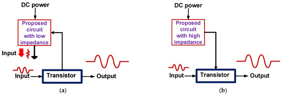
Figure 1.
Concept of novel Class-C pulsed power amplifier structures. Signal paths when (a) input signals were blocked in the bias circuit and (b) DC current was provided to the transistor.
Section 2 describes the operating mechanism of the proposed Class-C pulsed power amplifier and presents a detailed analysis of the operation of the proposed circuit with low- and high-impedance values. Section 3 demonstrates the improvements in the measured results when using the pulsed Class-C power amplifier with the proposed circuit. Section 4 presents the conclusion of the paper.
2. Materials and Methods
2.1. Implementation of Class-C Pulsed Power Amplifiers
The schematic and implemented printed circuit board of the Class-C pulsed power amplifier are shown in Figure 2. As shown in Figure 2a, the Class-C pulsed power amplifier with voltage divider was implemented as a two-stage power amplifier. Input and output matching circuits were used to obtain 50 Ω resistance at the input and output sides to minimize power reflections. A electrolytic capacitor (CGS1 and CDS1) and two decoupled capacitors (CGS2, CGS3, CDS2, and CDS3) were used to reduce the ripple current from the DC power supply [23]. A shunt choke inductor (Ld1) was used to avoid the voltage drop from the DC power supply. In the voltage divider, the DC bias voltage was determined by the ratio of the fixed resistor (RC1) to the variable resistor (RC2) because a single choke inductor has sufficiently large inductance to avoid the voltage reduction from two resistors. The primary transistor (H1) is an n-channel RF power transistor with a 945 MHz bandwidth. The power resistors were used to avoid component breakage under high-voltage operation.
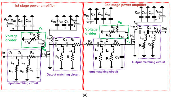
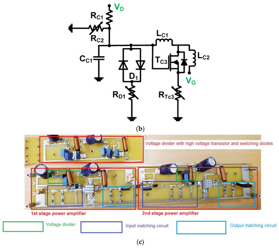
Figure 2.
(a) Schematic of Class-C pulsed power amplifier with voltage divider; (b) schematic of voltage divider integrated with transistor and switching diodes; and (c) implemented printed circuit board of Class-C pulsed power amplifier structures.
Figure 2b shows the proposed voltage divider with a high-voltage transistor and switching diodes. Two resistors (RD1 and RT3) were used to endure the high DC current due to the low equivalent resistance in the high-voltage switching diodes and the high-voltage n-channel transistor, working as a current sink path flowing from the input port and DC power supply simultaneously. A circuit with only a voltage divider and a one-choke inductor (LC2) was also used to avoid the voltage drop from the DC power supply. Another additional inductor (Lc1), combined with high-voltage transistors and switching diodes, merely worked to filter the high-current pulse coming from the input port. More detailed analysis is presented in the next section. Figure 2c shows the implemented two-stage Class-C pulsed power amplifiers on the fabricated printed circuit board.
2.2. Analysis of Class-C Pulsed Power Amplifiers
As described in Figure 1, the voltage divider with a high-voltage transistor and switching diodes must block unwanted input signals from VG point to VD point (Figure 2b) and pass the maximum possible DC voltages. Figure 3 shows the equivalent circuit model of the transistor and switching diodes.
Figure 3.
Equivalent circuit models of (a) switching diodes and (b) transistor.
As shown in Figure 3a, the equivalent circuit model of the high-voltage switching diodes (D1) is simplified into one capacitance (CD1) because the parasitic resistances of switching diodes are negligible [24,25,26]. Assuming the parasitic resistances of transistors are negligible, one high-voltage transistor (TC3) can be converted to have three parasitic capacitances, i.e., gate-source, gate-drain, and drain-source capacitances (CgsTC3, CgdTC3, and CdsTC3, respectively). To further simplify the equivalent circuit of the high-voltage transistor, the three parasitic capacitances were converted into one capacitance (CTC3). Therefore, the equivalent circuit model of the voltage divider with a high-voltage transistor and switching diodes can be obtained as illustrated in Figure 4.
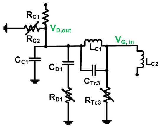
Figure 4.
Equivalent circuit models of voltage divider with high-voltage transistor and switching diodes.
As shown in Figure 4, the two resistors (RC1 and RC2) and one inductor (LC2) are precisely the same components obtained in a voltage divider; consequently, these components were removed to analyze the equivalent circuit. Excluding these components, the equivalent circuit has a typical π-network-type structure [27,28,29]. Therefore, the transfer function of the voltage divider with the high-voltage transistor and switching diodes can be obtained according to Equation (1).
where fc is the input frequency.
Because 4π2fc2Lc1CT3 is less than one and Lc1 (CD1 + CC1) is larger than 2πfcCD1Cc1RD1Lc1, the equivalent circuit model can be simplified into Equation (3). To reduce unwanted input signals, large capacitances (CD1 and CC1) and inductance (LC1) are preferable.
Another purpose of the voltage divider integrated with the high-voltage transistor and switching diodes is to reduce the DC voltage reduction. As shown in Figure 2b, the capacitor indicates an infinite impedance, and the inductance indicates zero impedance for DC analysis. Therefore, we can obtain an equivalent circuit model for DC analysis (Figure 5).
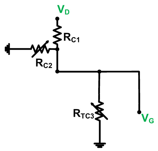
Figure 5.
Equivalent circuit models of voltage divider with high-voltage transistor and switching diodes for DC analysis.
If the resistor (RTC3) demonstrates a large resistance to avoid the flow of a DC current for the high-voltage transistor (TC3), the DC bias voltage can be similarly obtained between the independent voltage divider and the voltage divider with a high-voltage transistor and switching diodes. Therefore, the gate voltage (VG) can be obtained according to Equation (4). Therefore, this result shows that the gate voltages of the Class-C pulsed power amplifiers are the same.
where VD is the DC supply voltage.
The output power and DC power consumption equations of the Class-C pulsed power amplifiers with the independent voltage divider and with the voltage divider integrated with high-voltage transistor and switching diodes are the same. However, the equations are different for the conduction angles, output currents, and output voltages. As mentioned previously, the high-voltage transistor library for power amplifier design is not accurate for power amplifier simulation. Additionally, the output current and voltage of the Class-C pulsed power amplifier can be measured using voltage and current probes in the oscilloscope, thereby obtaining the measured performance of the Class-C pulsed power amplifiers as demonstrated in the subsequent section. The output power (Op) of the Class-C pulsed power amplifiers can be expressed according to Equation (5) [25,30].
where R0 is the output resistor, Φ is the conduction angle, and v0 and i0 are the output voltage and current, respectively, of the Class-C pulsed power amplifiers.
The DC power consumption (PD) of the Class-C pulsed power amplifiers can be expressed according to Equation (6) [25,30].
where VD is the DC supply voltage and Io is the DC current.
The transistor simulation libraries do not demonstrate high accuracy while designing a power amplifier, even for sub-decibel levels [31,32]. Therefore, a power amplifier designed using the simulation results was not considered in this research. However, an equivalent circuit model analysis and measured results of power amplifiers were considered to validate the proposed circuit.
3. Results and Discussion
3.1. Class-C Pulsed Power Performances
To verify the effect of the power transfer characteristic of ultrasonic transducers, the output power of the Class-C pulsed power amplifiers was measured. The ultrasonic transducers should be triggered by the single or multi-cycle pulse signals generated by the pulsed power amplifiers [33,34]. Therefore, we applied such pulse signals from the arbitrary function generator in the measurement.
Figure 6a,b shows the schematic and photograph of the output power measurement setup. The pulse sine waveform generated from an arbitrary function generator (DG5701, Rigol Inc., Beijing, China) was the input of the Class-C pulsed power amplifier. The amplified output power of the Class-C pulsed power amplifier after passing through a power attenuator was measured with the 100:1 high-voltage and high-current probes in the oscilloscope (MDO4104C, Tecktronix, Inc., Santa Clara, CA, USA). Figure 6c,d shows the measured power gain of the Class-C pulsed power amplifiers versus the input voltages and frequencies, respectively.
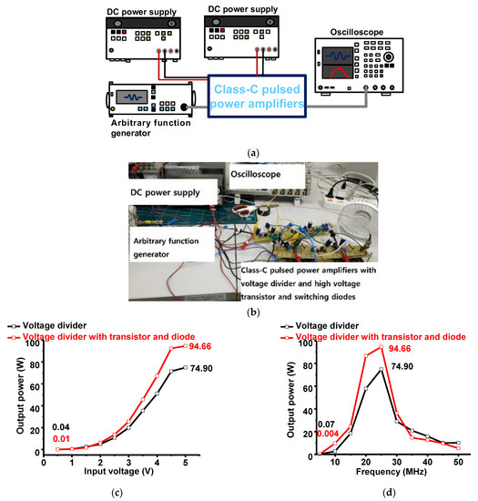
Figure 6.
(a) Measurement setup and (b) photograph of the measurement setup for Class-C pulsed power amplifier output power. The output power of a Class-C pulsed power amplifier with only a voltage divider and with voltage divider integrated with a high-voltage transistor and switching diodes versus (c) input voltage and (d) frequency.
As shown in Figure 6c, the measured output power when using the voltage divider with a high-voltage transistor and switching diodes (94.66 W) was higher than that when using the voltage divider independently (74.90 W) at 25 MHz and 5 Vp-p input. As shown in Figure 6d, the measured power gain of the Class-C pulsed power amplifier with the voltage divider integrated with a high-voltage transistor and switching diodes was also higher than that of the Class-C pulsed power amplifier with the independent voltage divider at 20 and 25 MHz.
Figure 7 shows the measured DC power consumption versus the input voltage and frequency of the Class-C pulsed power amplifiers with an independent voltage divider and with a voltage divider integrated with high-voltage transistor and switching diodes. To evaluate the battery power consumption in handheld ultrasound instruments, the DC power consumption of the power amplifier must be evaluated as the amplifier is one of the most power-consuming components in the handheld ultrasound instrument. From Figure 7, it can be observed that the measured DC power consumption of the Class-C pulsed power amplifiers is constant. As shown in Figure 7, the measured DC power consumption corresponding to the input voltage or frequency of the Class-C pulsed power amplifier with the voltage divider integrated with a high-voltage transistor and switching diodes (2125 mW) was less than that with the independent voltage divider (2725 mW). Therefore, the proposed circuit is more suitable for reducing battery consumption in handheld ultrasound instruments.
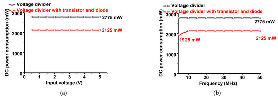
Figure 7.
DC power consumption versus (a) input voltage and (b) frequency of the Class-C pulsed power amplifier with an independent voltage divider and with a voltage divider integrated with high-voltage transistor and switching diodes.
3.2. Ultrasonic Transducer Performances with Class-C Pulsed and Proposed Power Amplifiers
Pulse-echo measurement is a benchmark for characterizing the performances of the developed ultrasonic transducers or hardware electronics [35]. This is because the bandwidth and amplitude of the echo signals generated by ultrasonic transducers are directly related to the image resolution and sensitivity of the ultrasound instrument, respectively [36]. Figure 8a,b shows the pulse-echo measurement setup and its photograph, respectively, when using the developed power amplifier and ultrasonic transducers. The arbitrary function generator generated five cycles, 5 Vp-p, and a pulsed sinusoidal waveform of 25 MHz. The received waveform was amplified by the designed Class-C pulsed power amplifier, triggering 0.25” immersion type ultrasonic transducers (V324, Olympus Corporation, Waltham, MA, USA). When the amplified pulse signals trigger the ultrasonic transducer, the discharged pulse signal can pass through the preamplifier. Therefore, a limiter constructed using a 50 Ω resistor shunt with a parallel diode was used to protect the preamplifier [37]. The acoustic echo signal received from the quartz target was converted into an electrical echo signal by using the ultrasonic transducers. The weak electrical echo signal was amplified using a 6 dB gain non-inverting preamplifier (AD8001, Analog Devices, San Jose, CA, USA) to display the echo signal on the oscilloscope.
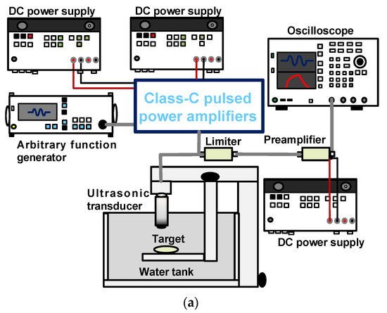
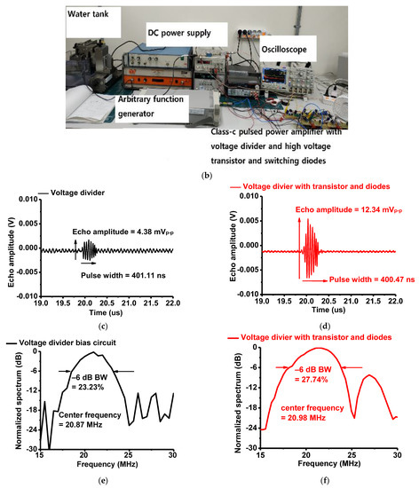
Figure 8.
(a) Schematic and (b) photograph of the pulse-echo measurement setup. Measured echo amplitude of the ultrasonic transducer trigger by the Class-C pulsed power amplifier when using (c) an independent voltage divider and (d) a voltage divider with high-voltage transistor and switching diode. Measured echo bandwidth of an ultrasonic transducer triggered by a Class-C pulsed power amplifier when using (e) an independent voltage divider and (f) a voltage divider with a high-voltage transistor and switching diode.
The echo amplitude and pulse width were measured as these parameters are related to the sensitivity and axial resolution of the ultrasonic transducer, respectively [38]. The echo amplitude is the peak-to-peak amplitude difference between the highest positive voltage and the lowest negative voltage. As shown in Figure 8c,d, the echo amplitude when using the voltage divider with high-voltage transistor and switching diodes was 2.81 times higher than when using the independent voltage divider. The pulse widths when using the independent voltage divider and when using the voltage divider with high-voltage transistor and switching diodes were similar to each other (401.11 ns and 400.47 ns, respectively). The pulsed power amplifier design is required to consider the occurrence of a larger ring-down effect when compared to a continuous wave power amplifier [26,39]. The ring-down voltages are also related to the axial resolutions of the ultrasound instruments [40].
The −6 dB bandwidth and center frequency are related to the image resolution of the ultrasonic transducers. From Figure 8e,f, it can be observed that the bandwidth when using the voltage divider with high-voltage transistor and switching diodes was 17.26% superior to that when using the voltage divider independently. The center frequencies when using the voltage divider independently and when using the voltage divider with high-voltage transistor and switching diodes were similar to each other (20.87 and 20.98 MHz, respectively). Therefore, we can confirm that the proposed circuit improves the performance of the pulsed power amplifier with respect to the echo amplitudes, ring-down voltages, and −6 dB bandwidth.
Table 1 shows the comparison performance of the developed power amplifier with the currently developed power amplifier for ultrasound applications.

Table 1.
Summarized performance of the comparison data of the power amplifiers.
4. Conclusions
A Class-C pulsed power amplifier with a voltage divider integrated with high-voltage transistor and switching diodes was proposed to improve the thermal evaporation and increase the echo amplitude because compact-sized handheld ultrasound instruments demonstrate the limitations of unwanted heat generation and limited battery life. Therefore, this scheme can aid in increasing the number of ultrasonic transducer array elements, thus increasing the sensitivity while also improving the field of view.
The Class-C pulsed power amplifier was used to reduce the thermal problem caused by the low conduction angle of the current. However, this Class-C pulsed power amplifier demonstrated a technical challenge for obtaining stable DC bias voltages that can sustain consistent performance when compared to a Class-A pulsed power amplifier. Therefore, a voltage divider with a high-voltage transistor and a switching diode was applied to the Class-C pulsed power amplifier.
The measured output power of the Class-C pulsed power amplifier when using the voltage divider integrated with the high-voltage transistor and switching diode (94.66 W) was higher than that of the Class-C pulsed power amplifier when using the voltage divider independently (74.90 W), when 25 MHz, five-cycle, and 5 Vp-p input voltages were provided. In addition, the measured DC power consumption of the Class-C pulsed power amplifier when using the voltage divider with high-voltage transistor and switching diode (2125 mW) was lower than that of the Class-C pulsed power amplifier when using the voltage divider independently (2775 mW), for the same input conditions. Therefore, the Class-C pulsed power amplifier when using the voltage divider with a high-voltage transistor and switching diode demonstrated better suitability for handheld ultrasound instruments.
To test the capability of the proposed circuit, a typical pulse-echo measurement was performed. The echo amplitude when using the voltage divider with a high-voltage transistor and switching diodes (12.34 mVp-p) was higher than that when using the voltage divider independently (4.38 mVp-p). The −6 dB bandwidth when using the voltage divider with high-voltage transistor and switching diodes (27.74%) was also wider than that when using the voltage divider independently (23.23%). Therefore, the proposed circuit can be considered as a potential candidate to improve the sensitivity and image resolution of handheld ultrasound instruments.
Author Contributions
Conceptualization, H.C.; methodology, H.C.; formal analysis, H.C.; writing—original draft preparation, H.C. All authors have read and agreed to the published version of the manuscript.
Funding
This work was supported by the National Research Foundation of Korea (NRF) grant funded by the Korea government (MSIT) (No. 2020R1A2C4001606).
Institutional Review Board Statement
Not applicable.
Informed Consent Statement
Not applicable.
Data Availability Statement
The data presented in this study are included within the article.
Conflicts of Interest
The authors declare no conflict of interest.
References
- Daniels, J.M.; Hoppmann, R.A. Practical Point-of-Care Medical Ultrasound; Springer: New York, NJ, USA, 2016. [Google Scholar]
- Kalaitzakis, E.; Vilmann, P.; Bhutani, M.S. Therapeutic Endoscopic Ultrasound; Springer: Berlin, Germany, 2020. [Google Scholar]
- Mattoon, J.S.; Sellon, R.K.; Berry, C.R. Small Animal Diagnostic Ultrasound; Elsevier Health Sciences: Amsterdam, The Netherlands, 2020. [Google Scholar]
- Arnau, A. Piezoelectric Transducers and Applications; Springer: Berlin, German, 2004; Volume 2004. [Google Scholar]
- Safari, A.; Akdogan, E.K. Piezoelectric and Acoustic Materials for Transducer Applications; Springer Science & Business Media: Berlin, Germany, 2008. [Google Scholar]
- Zhou, Q.; Lam, K.H.; Zheng, H.; Qiu, W.; Shung, K.K. Piezoelectric single crystal ultrasonic transducers for biomedical applications. Prog. Mater. Sci. 2014, 66, 87–111. [Google Scholar] [CrossRef] [PubMed]
- Zennaro, F.; Neri, E.; Nappi, F.; Grosso, D.; Triunfo, R.; Cabras, F.; Frexia, F.; Norbedo, S.; Guastalla, P.; Gregori, M. Real-Time Tele-Mentored Low Cost “Point-of-Care US” in the Hands of Paediatricians in the Emergency Department: Diagnostic Accuracy Compared to Expert Radiologists. PLoS ONE 2016, 11, e0164539. [Google Scholar] [CrossRef] [PubMed]
- Soni, N.J.; Arntfield, R.; Kory, P. Point of Care Ultrasound; Elsevier Health Sciences: Oxford, UK, 2019. [Google Scholar]
- Machi, J.; Staren, E.D. Ultrasound for Surgeons; Lippincott Williams & Wilkins: Philadelpia, PA, USA, 2005. [Google Scholar]
- Vijaya, M. Piezoelectric Materials and Devices: Applications in Engineering and Medical Sciences; CRC Press: Boca Raton, FL, USA, 2016. [Google Scholar]
- Kamaya, A.; Wong-You-Cheong, J.; Woodward, P.J. Diagnostic Ultrasound for Sonographers; Elsevier Health Sciences: Amsterdam, The Netherlands, 2019. [Google Scholar]
- Adhikari, S.; Blaivas, M. The Ultimate Guide to Point-of-Care Ultrasound-Guided Procedures; Springer: Berlin, Germany, 2019. [Google Scholar]
- Karlen, W. Mobile Point-of-Care Monitors and Diagnostic Device Design; CRC Press: Boca Raton, FL, USA, 2014. [Google Scholar]
- Baston, C.M.; Moore, C.; Dean, A.J.; Panebianco, N. Pocket Guide to POCUS: Point-of-Care Tips for Point-of-Care Ultrasound; McGraw Hill Education, Incorporated: New York, NJ, USA, 2019. [Google Scholar]
- Miele, F.R. Ultrasound Physics & Instrumentation; Pegasus Lectures, Inc.: Forney, TX, USA, 2013. [Google Scholar]
- Uchino, K. Advanced Piezoelectric Materials: Science and Technology; Woodhead Publishing: Cambridge, UK, 2017. [Google Scholar]
- Edelman, S.K. Understanding Ultrasound Physics; Baker & Taylor: Charlotte, NC, USA, 2012. [Google Scholar]
- Qiu, W.; Wang, X.; Chen, Y.; Fu, Q.; Su, M.; Zhang, L.; Xia, J.; Dai, J.; Zhang, Y.; Zheng, H. A Modulated Excitation Imaging System for Intravascular Ultrasound. IEEE Trans. Biomed. Eng. 2016, 64, 1935–1942. [Google Scholar] [CrossRef] [PubMed]
- Gao, Z.; Gui, P. A look-up-table digital predistortion technique for high-voltage power amplifiers in ultrasonic applications. IEEE Trans. Ultrason. Ferroelectr. Freq. Control 2012, 59, 1550–1557. [Google Scholar] [PubMed]
- Capineri, L. A 15 MHz bandwidth, 60 Vpp, low distortion power amplifier for driving high power piezoelectric transducers. Rev. Sci. Instrum. 2014, 85, 104701. [Google Scholar] [CrossRef] [PubMed]
- Bianchi, D.; Quaglia, F.; Mazzanti, A.; Svelto, F. Analysis and Design of a High Voltage Integrated Class-B Amplifier for Ultra-Sound Transducers. IEEE Trans. Circuits Syst. I Regul. Pap. 2014, 61, 1942–1951. [Google Scholar] [CrossRef]
- Albulet, M. RF Power Amplifiers; SciTech Publishing: London, UK, 2001. [Google Scholar]
- Nguyen, C. Radio-Frequency Integrated-Circuit Engineering; John Wiley & Sons: Hoboken, NJ, USA, 2015. [Google Scholar]
- Johns, D.A.; Martin, K. Analog Integrated Circuit Design; John Wiley & Sons: New York, NY, USA, 2008. [Google Scholar]
- Lee, T.H. The Design of CMOS Radio-Frequency Integrated Circuits; Cambridge University Press: Cambridge, UK, 2006. [Google Scholar]
- Razavi, B. Design of Analog CMOS Integrated Circuits; McGraw-Hill Science: New York, NJ, USA, 2016. [Google Scholar]
- Allen, P.E.; Holberg, D.R. CMOS Analog Circuit Design; Oxford University Press: Oxford, UK, 2002. [Google Scholar]
- Ludwig, R. RF Circuit Design: Theory & Applications; Pearson Education: London, UK, 2000. [Google Scholar]
- Sedra, A.S.; Smith, K.C.; Carusone, T.C.; Gaudet, V. Microelectronic Circuits; Oxford University Press: New York, NJ, USA, 2016. [Google Scholar]
- Cripps, S.C. RF Power Amplifiers for Wireless Communications; Artech House: Norwood, MA, USA, 2006. [Google Scholar]
- Cripps, S.C. Advanced Techniques in RF Power Amplifier Design; Artech House: Norwood, MA, USA, 2002. [Google Scholar]
- Vuolevi, J.; Rahkonen, T. Distortion in RF Power Amplifiers; Artech house: London, UK, 2003. [Google Scholar]
- Kripfgans, O.D.; Chan, H.-L. Ultrasonic Imaging: Physics and Mechanism. In Dental Ultrasound in Periodontology and Implantology: Examination, Diagnosis and Treatment Outcome Evaluation; Chan, H.-L., Kripfgans, O.D., Eds.; Springer: Berlin/Heidelberg, Germany, 2021; pp. 1–38. [Google Scholar] [CrossRef]
- Shutilov, V.A.; Alferieff, M.E. Fundamental Physics of Ultrasound; CRC Press: Boca Raton, FL, USA, 2020. [Google Scholar]
- Szabo, T.L. Diagnostic Ultrasound Imaging: Inside Out; Elsevier Academic Press: London, UK, 2013. [Google Scholar]
- Shung, K.K. Diagnostic Ultrasound: Imaging and Blood Flow Measurements; Taylor & Francis: Boca Raton, FL, USA, 2015. [Google Scholar]
- Shung, K.K.; Smith, M.; Tsui, B.M. Principles of Medical Imaging; Academic Press: Cambridge, MA, USA, 2012. [Google Scholar]
- Hoskins, P.R.; Martin, K.; Thrush, A. Diagnostic Ultrasound: Physics and Equipment; Cambridge University Press: Cambridge, UK, 2019. [Google Scholar]
- Narayanaswami, R.S. RF CMOS Class C power Amplifiers for Wireless Communications; University of California, Berkeley: Berkeley, CA, USA, 2001. [Google Scholar]
- Suri, J.S.; Kathuria, C.; Chang, R.-F.; Molinar, F.; Fenster, A. Advances in Diagnostic and Therapeutic Ultrasound Imaging; Artech House: Norwood, MA, USA, 2008. [Google Scholar]
- Choi, H. Prelinearized Class-B Power Amplifier for Piezoelectric Transducers and Portable Ultrasound Systems. Sensors 2019, 19, 287. [Google Scholar] [CrossRef] [PubMed]
- Bianchi, D.; Quaglia, F.; Mazzanti, A.; Svelto, F. A 90Vpp 720MHz GBW linear power amplifier for ultrasound imaging transmitters in BCD6-SOI. In Proceedings of the 2012 IEEE International Solid-State Circuits Conference, San Francisco, CA, USA, 19–23 February 2012; pp. 370–372. [Google Scholar]
- Ku, P.-C.; Shih, K.-Y.; Lu, L.-H. A high-voltage DAC-based transmitter for coded signals in high frequency ultrasound imaging applications. IEEE Trans. Circuits Syst. I Regul. Pap. 2018, 65, 2797–2809. [Google Scholar] [CrossRef]
- Gao, Z.; Gui, P.; Jordanger, R. An integrated high-voltage low-distortion current-feedback linear power amplifier for ultrasound transmitters using digital predistortion and dynamic current biasing techniques. IEEE Trans. Circuits Syst. II Express Briefs 2014, 61, 373–377. [Google Scholar] [CrossRef]
- Ghisu, D.; Gambero, A.; Terenzi, M.; Ricotti, G.; Moroni, A.; Rossi, S. 180Vpp output voltage, 24MHz bandwidth, low power class AB current-feedback high voltage amplifier for ultrasound transmitters. In Proceedings of the 2018 IEEE Custom Integrated Circuits Conference (CICC), San Diego, CA, USA, 8–11 April 2018; pp. 1–4. [Google Scholar]
- Choi, H. Class-C Linearized Amplifier for Portable Ultrasound Instruments. Sensors 2019, 19, 898. [Google Scholar] [CrossRef] [PubMed]
- Choi, H. Development of a Class-C Power Amplifier with Diode Expander Architecture for Point-of-Care Ultrasound Systems. Micromachines 2019, 10, 697. [Google Scholar] [CrossRef] [PubMed]
- Nielsen, D.; Knott, A.; Andersen, M.A.E. A high-voltage class D audio amplifier for dielectric elastomer transducers. In Proceedings of the 2014 IEEE Applied Power Electronics Conference and Exposition—APEC 2014, Fort Worth, TX, USA, 16–20 March 2014; pp. 3278–3283. [Google Scholar]
- Christoffersen, C.; Wong, W.; Pichardo, S.; Togtema, G.; Curiel, L. Class-DE ultrasound transducer driver for HIFU therapy. IEEE Trans. Biomed. Circuits Syst. 2016, 10, 375–382. [Google Scholar] [CrossRef] [PubMed]
- Yuan, T.; Dong, X.; Shekhani, H.; Li, C.; Maida, Y.; Tou, T.; Uchino, K. Driving an inductive piezoelectric transducer with class E inverter. Sens. Actuators A 2017, 261, 219–227. [Google Scholar] [CrossRef]
- Dong, X.; Yuan, T.; Hu, M.; Shekhani, H.; Maida, Y.; Tou, T.; Uchino, K. Driving frequency optimization of a piezoelectric transducer and the power supply development. Rev. Sci. Instrum. 2016, 87, 105003. [Google Scholar] [PubMed]
- Wei, X.; Yang, Y.; Yao, W.; Zhang, L. Design of full bridge high voltage pulser for sandwiched piezoelectric ultrasonic transducers used in long rail detection. Appl. Acoust. 2019, 149, 15–24. [Google Scholar] [CrossRef]


Publisher’s Note: MDPI stays neutral with regard to jurisdictional claims in published maps and institutional affiliations. |
© 2022 by the author. Licensee MDPI, Basel, Switzerland. This article is an open access article distributed under the terms and conditions of the Creative Commons Attribution (CC BY) license (https://creativecommons.org/licenses/by/4.0/).