1. Introduction
Induction heating (IH) is commonly used in residential, industrial, and medical applications because it has features such as being hygienic; using non-contact heating; providing protection; and having higher competence, higher power density, and specific power control characteristics [
1]. The electromagnetic induction principle is used to heat the object directly via the eddy current developed on the load due to
loss [
2]. The heat depth of penetration of the load depends on the material’s skin depth [
3] and the magnitude of the heat depends directly on the frequency of the supply. Therefore, for any real-time applications, the selection of an appropriate operating frequency affects the heating capacity. The switching frequency generally varies from 5 kHz to 1000 kHz, with a load handling capacity of 500 kW [
4].
In the recent past, high-frequency resonant inverters with minimum switching losses have enticed researchers to study IH applications. The inverter switches are operated either in zero voltage switching (ZVS) or zero current switching (ZCS) with higher power density, higher efficiency, and light weight [
5,
6]. Based on the arrangement of the resonant capacitor with respect to the IH load, the inverters are termed as either series-resonant or parallel-resonant inverters. The series-resonant inverter with the voltage source inverter offers better overall performance than the parallel-resonant inverter [
7]. Generally, a voltage-source full-bridge series-resonant inverter is preferred for medium-power applications, ranging from 1 kW to 5 kW [
8].
Single-switch resonant inverters are used in IH systems where the power requirement is less than 2 kW. Shenkman et al. used a single-switch parallel-resonant AC–AC converter for IH applications [
9]. High-frequency ac (HFAC) supply was generated with the single switch connected in series with the supply voltage. The source power factor was improved by an LC filter. The variable frequency power control scheme increased the switching losses. This problem was overcome by using a multi-cycle modulation control technique with a fixed frequency [
10]. Two bidirectional semi-conductor SiC junction gate field effect transistor devices were used to convert 50 Hz AC to HFAC. Both switches were operated in soft switching mode to reduce the switching losses.
A half-bridge (HB) series-resonant inverter (SRI) is preferred for applications in which the power ratings range from 2 kW to 4 kW. Ahmed et al. developed a boost HB inverter with an LC branch at the source side [
11]. This branch reduces the DC and high-frequency components on the input side, resulting in a higher efficiency. An additional LC network increases the system time constant. Forest et al. developed a multi-winding induction coil-fed IH system to handle irregular shapes of the load [
12]. In this system, square and rectangular coils were used and power control was carried out by adjusting the inverter switching frequency. Lucia et al. developed a control algorithm for estimating the load parameters under dynamic variations [
13]. The inverter switches were operated with a switching frequency from 20 to 100 kHz, and a control scheme was implemented using a field-programmable gate array (FPGA) controller. Load inductance and resistance were measured for various switching frequencies. Lucia et al. developed a multiple coil-based induction cooking system to deliver power to many loads [
14]. The output power was controlled using the PDM technique with minimum switching losses. Lucia et al. developed a multi-inverter operated in discontinuous conduction mode for better efficiency during light load conditions [
15].
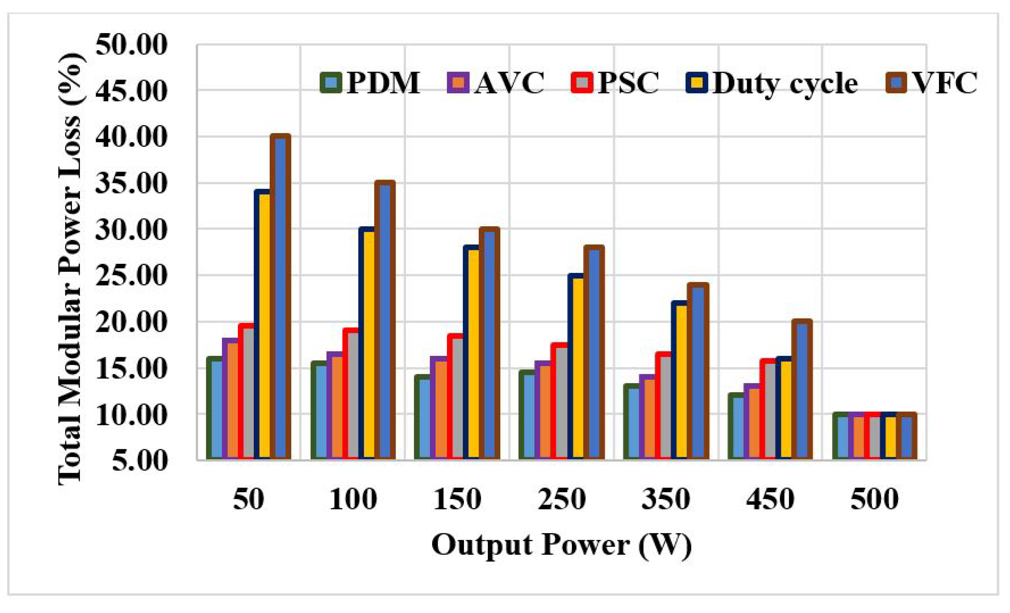
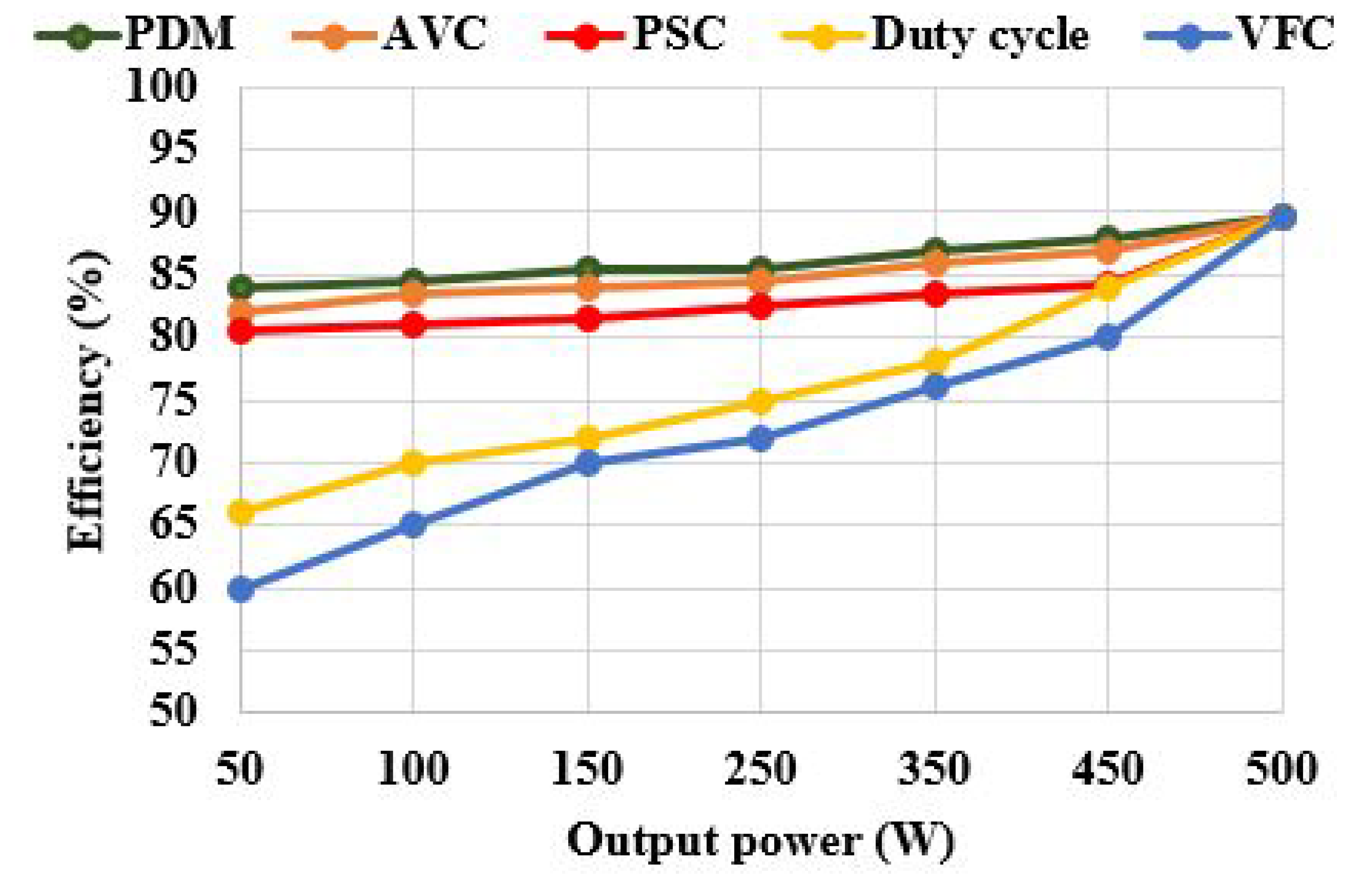
Power control plays an important role in IH systems. For metal melting applications, mainly pulse width modulation (PWM), pulse density modulation (PDM), asymmetric duty cycle control (ADC), phase shift control (PSC), and variable frequency (VF) control are employed to meet the requirements. A simple DC link PWM control using a thyristor-based rectifier with an input inductor and a DC link capacitor were used to regulate the output voltage [
16]. The bulky DC link capacitor increases the overall size of the module. In general, the VF control was used to control the output power for a fixed load [
17]. However, ZVS is not feasible if the inverter is operated below the resonant frequency. For constant load operation, pulse width modulation is preferred to regulate the output power based on duty cycle control. This results in a smaller range of soft switching [
18]. The efficiency of a PSC-fed inverter was found to be high at a duty cycle greater than 90% [
19]. In addition, PDM and AVC control techniques provide better soft-switching ranges. PDM achieves greater efficiency, a wide range of set power control, and soft switching among the above control techniques [
20].
In wireless power transfer applications, the self-resonating coil is often used, and its preference depends on the dimensions, frequency, and choice of applications [
21]. The virtual capacitance of the coil results in either a series or a parallel resonance depending on the coil structure. In parallel resonance, the magnitude of the impedance seen from the source side is higher, which results in less current being drawn from the supply. Thus, the magnetic field stored in the coil reduces, which results in less heat generation. This problem is overcome by a current source inverter (CSI) [
22], but it draws more reactive power on the secondary side of the coil. These issues are mitigated in series resonance-based bifilar coil [
23]. Hence, for real-time heating applications, an RLC series resonance-based bifilar coil is preferred [
24]. A capacitorless IH system is proposed in [
25], with an RLC series resonance-based bifilar coil.
The main purpose of this work is to perform power control with various modulation techniques such as duty cycle control, VF, PDM, AD,C and PSC to enhance the performance of the bifilar coil-based IH system developed in [
25]. Additionally, well-suited modulation techniques are needed for IH systems with less switching loss, a wide range of power control, and a fast heat rate. The developed system decreases the number of resonating components, which reduces the total system size, and uses a suitable control technique for smooth variation with less switching losses.
The rest of this paper is organized as follows:
Section 2 describes the circuit description of a bifilar coil-based IH system. Various power control strategies are summarized in
Section 3. An experimental validation of various control techniques is performed in
Section 4. A summary of the discussions on the experimental results is provided in
Section 5. The conclusions of this paper are presented in
Section 6.
4. Experimental Results
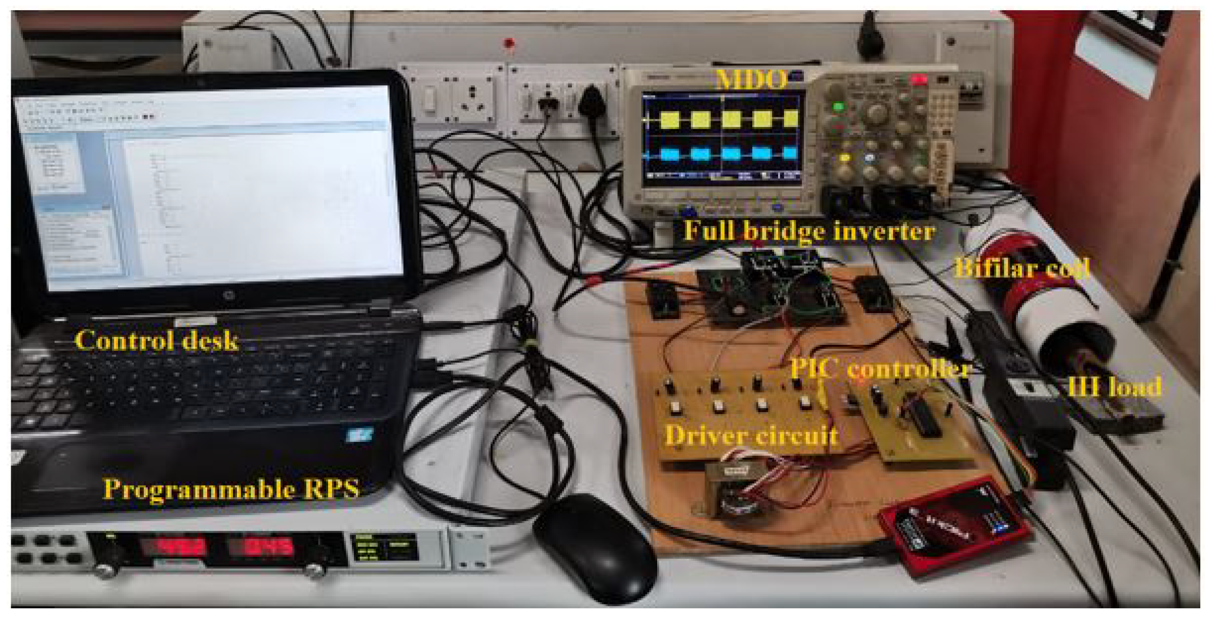
The experimental validation of a bifilar coil-based IH system was performed using an FB inverter with four H20R1203 IGBT power switches. Various control techniques were implemented using PIC16F877A micro controller to obtain HFAC at the load terminal. The TLP250 driver IC amplifies the switching pulses, the SIGLENT CP4060 current probe is used to measure the current, and the digital oscilloscope MDO3024 was used to record the waveform. The advanced FLIR E75 24 thermal imager was used to record the thermal distribution of the load.
The work coil is made with 60 turns of 17 AWG single-layer enamelled-copper wire. The work-piece consists of a metal bar with 25 cm height and 2.5 cm radius. A thermal insulator was placed between the work coil and the work-piece. The design specifications are listed in
Table 1.
Figure 6 illustrates the experimental setup for the bifilar coil-based IH system. The experiment was performed to analyze the performance of the IH system in terms of efficiency, power control, and heat transfer rate (16.5
C/min) for various control techniques.
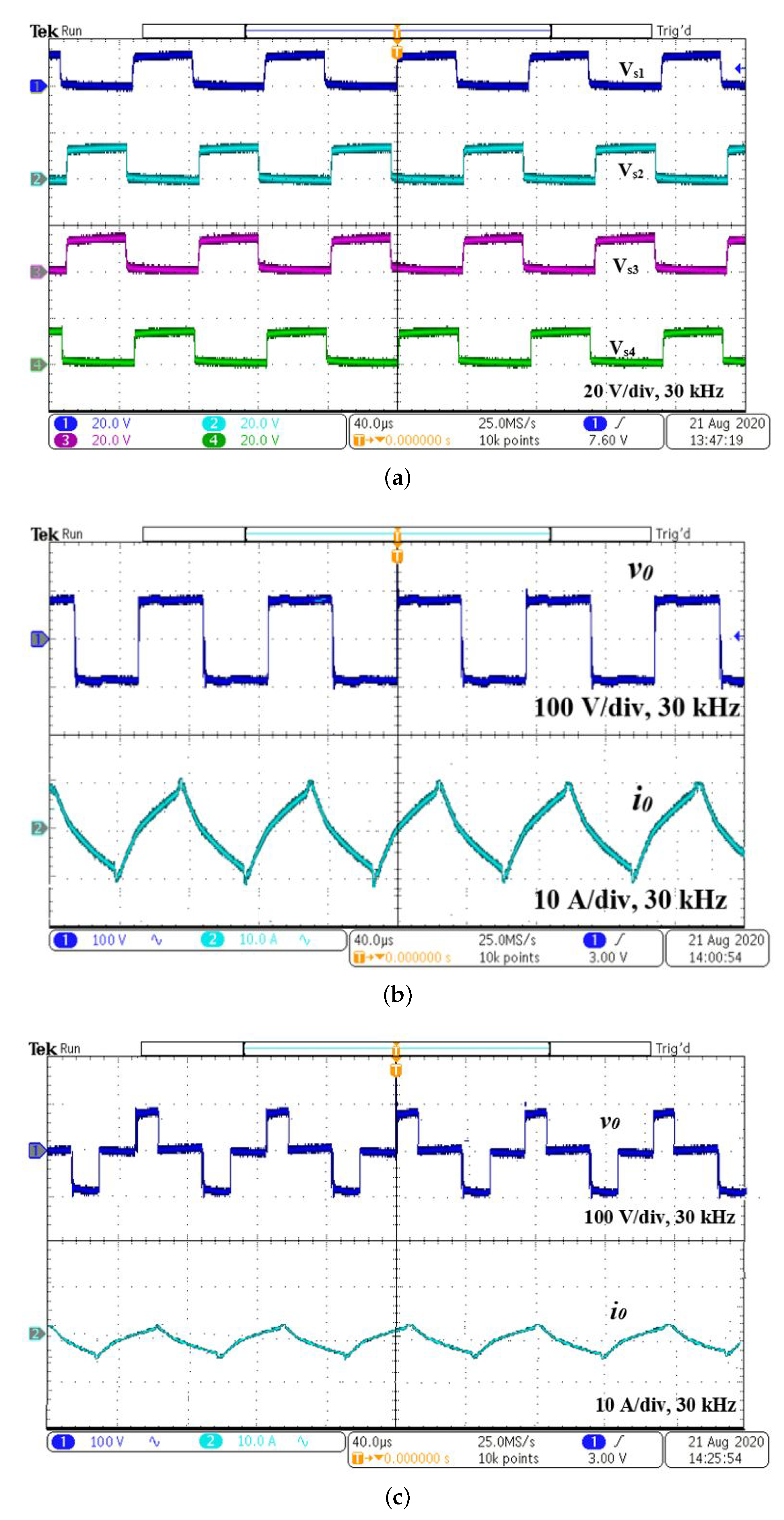
4.1. Pulse Duty Cycle Control
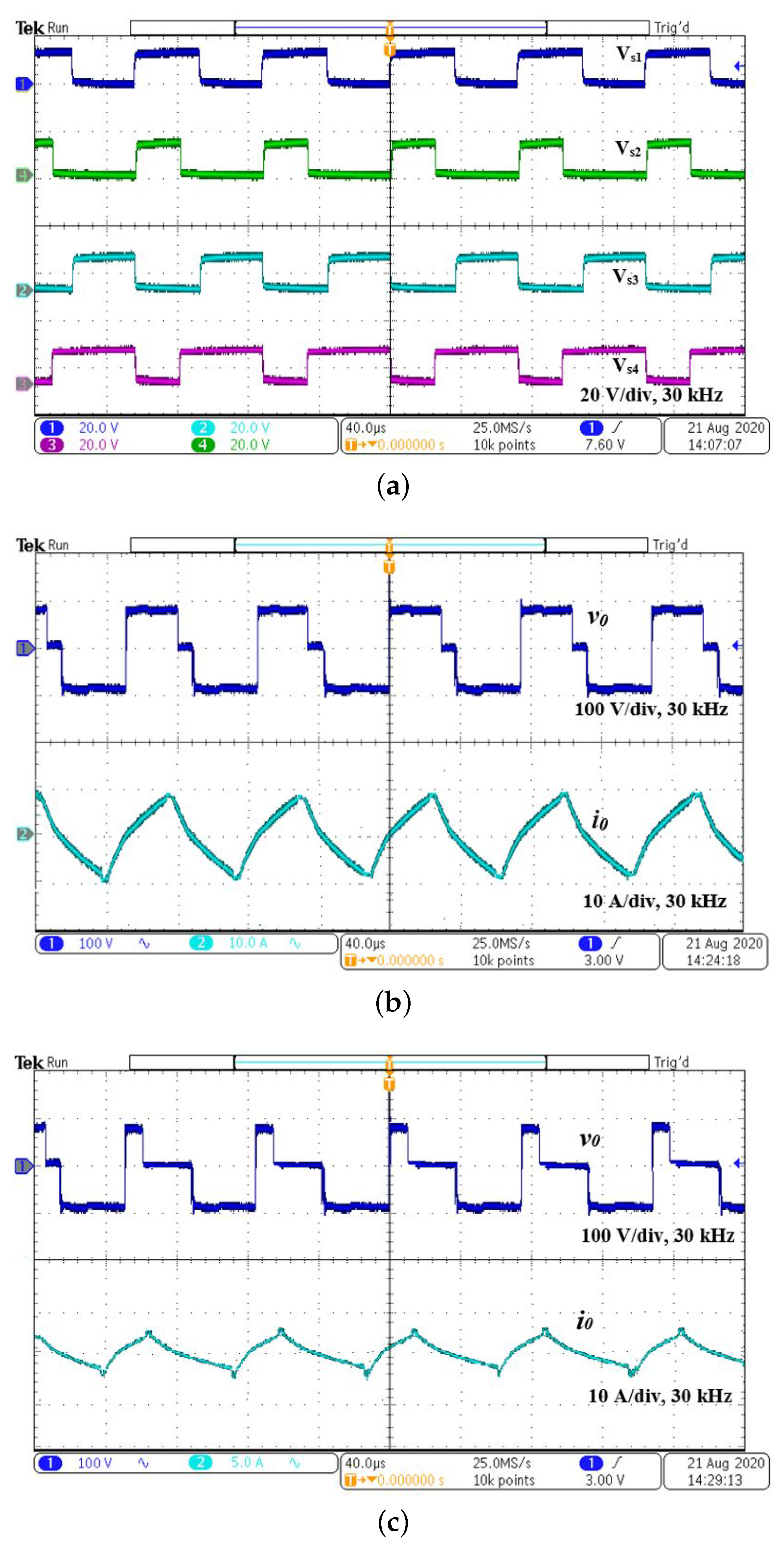
The experimental results of the IH system with pulse duty cycle control are shown in
Figure 7. The switching pulses and output voltage
and current
waveforms for 50% pulse duty cycle are shown in
Figure 7a,b, respectively. The output voltage and current waveforms for 10% pulse duty cycle is shown in
Figure 7c. The pulse width variation reduces
and
. At 50% pulse duty cycle and 30 kHz switching frequency, the rms value of the output voltage is 70.71 V and the current is 7.07 A. The output power
is 7.07
× 10 = 500 W for 10
equivalent resistance. The input power is calculated as
= 80 × 6.97 = 558 W. The efficiency for 500 W is 89.6%, and for other pulse duty cycle, it is given in
Table 2. As it draws more current from the supply, for lower values of duty cycle, the efficiency of the system decreases. The switch (
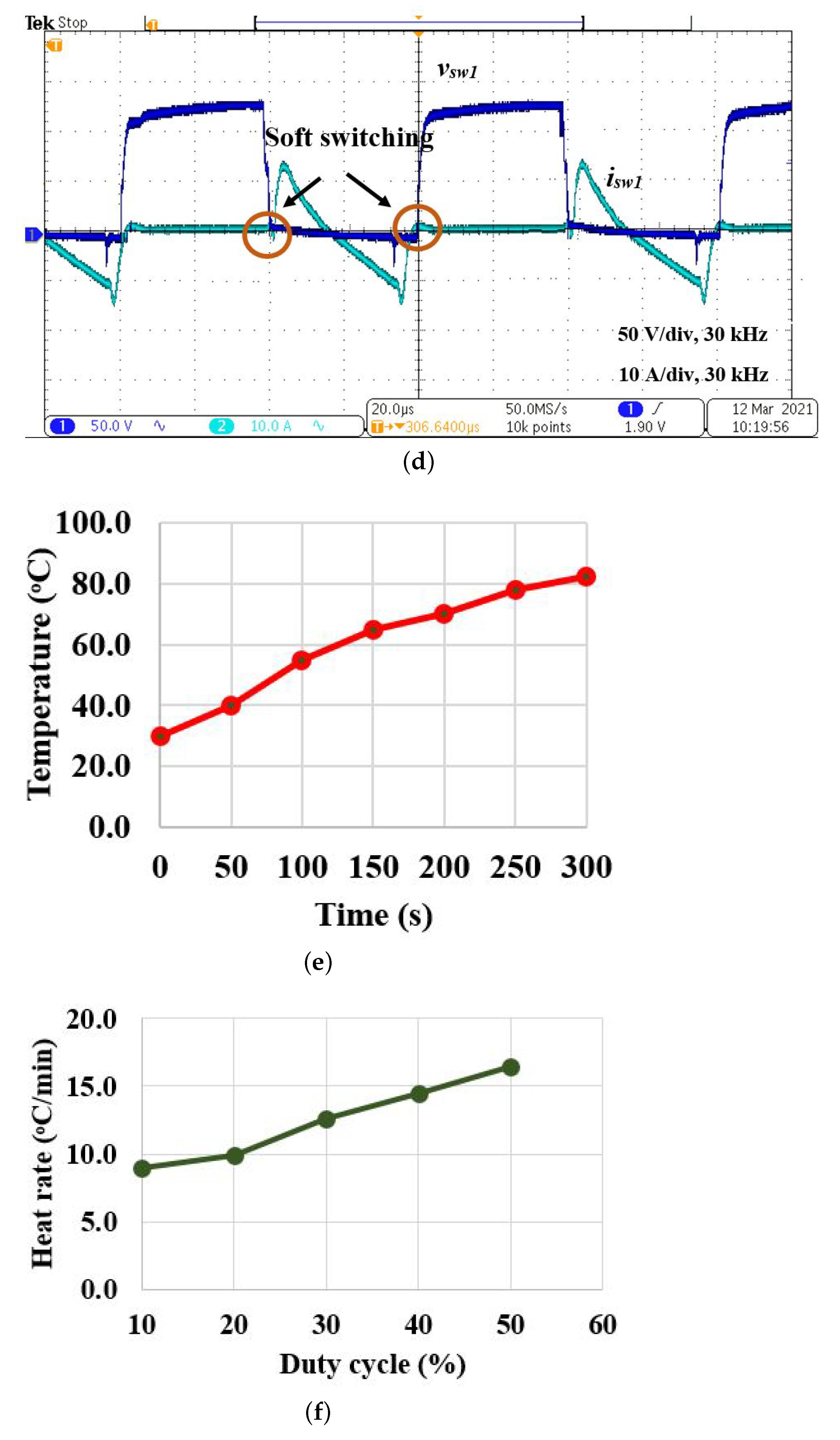
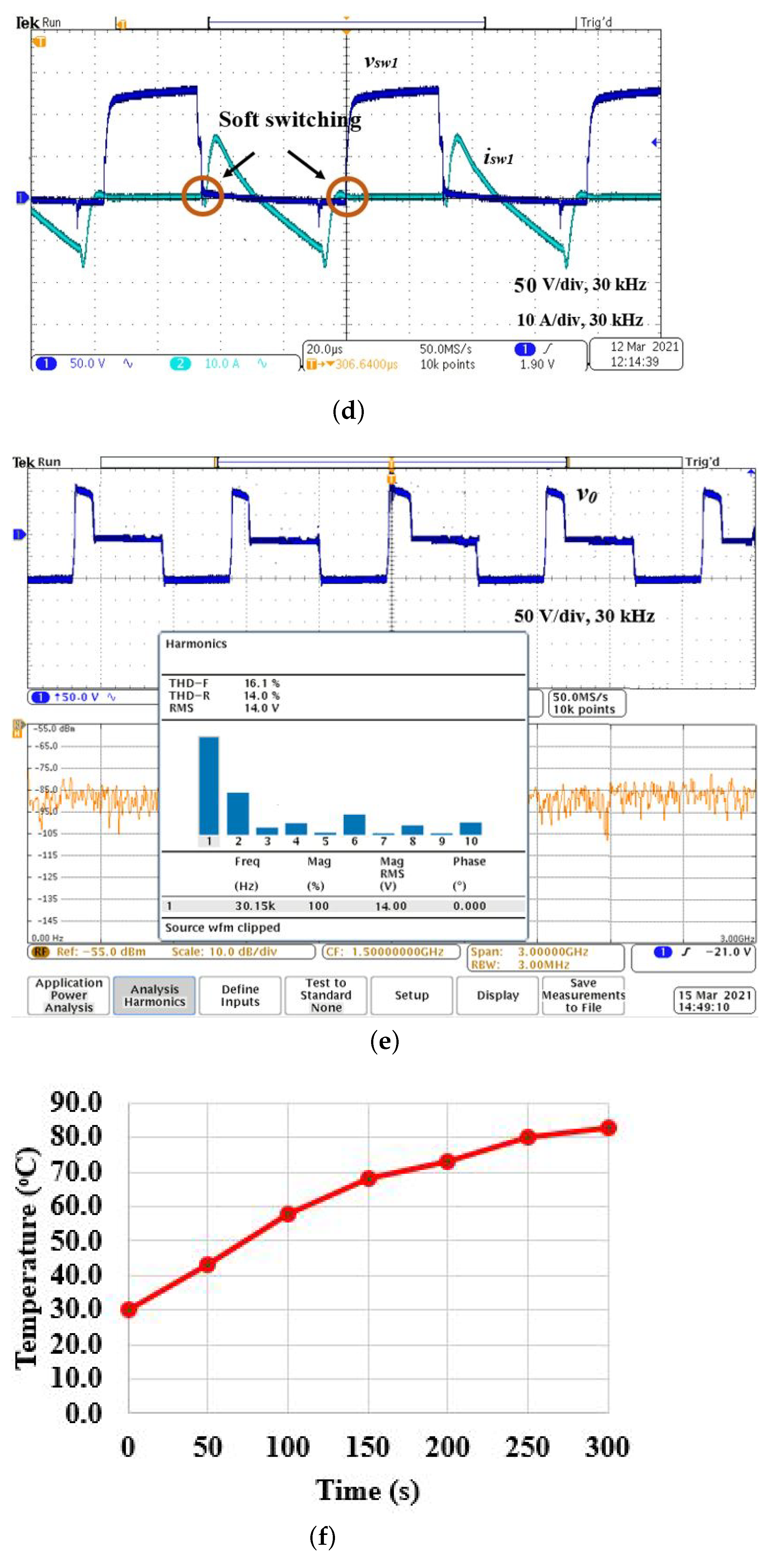
) voltage and current waveforms for 50% pulse duty cycle are shown in
Figure 7d. It is inferred that soft switching exists during the on and off periods, which reduces the switching losses. The variation in the temperature with respect to time for 500 W output power is illustrated in
Figure 7e. A temperature rise is noted for various duty cycle with the time interval of 5 min, and the heat rate is calculated. The heat rate for various duty cycles is shown in
Figure 7f. It is noted that the heat increases and attains 82.5
C at 50% duty cycle for a period of 5 min. The thermal image for various pulse duty cycle is illustrated in
Figure 7g. It is inferred that the heat increases with an increase in pulse duty cycle. The pulse duty ratio with 50% denotes a 50% positive half cycle and a 50% negative half cycle for the 180
conduction mode in which the corresponding load voltage duty ratio is 100%.
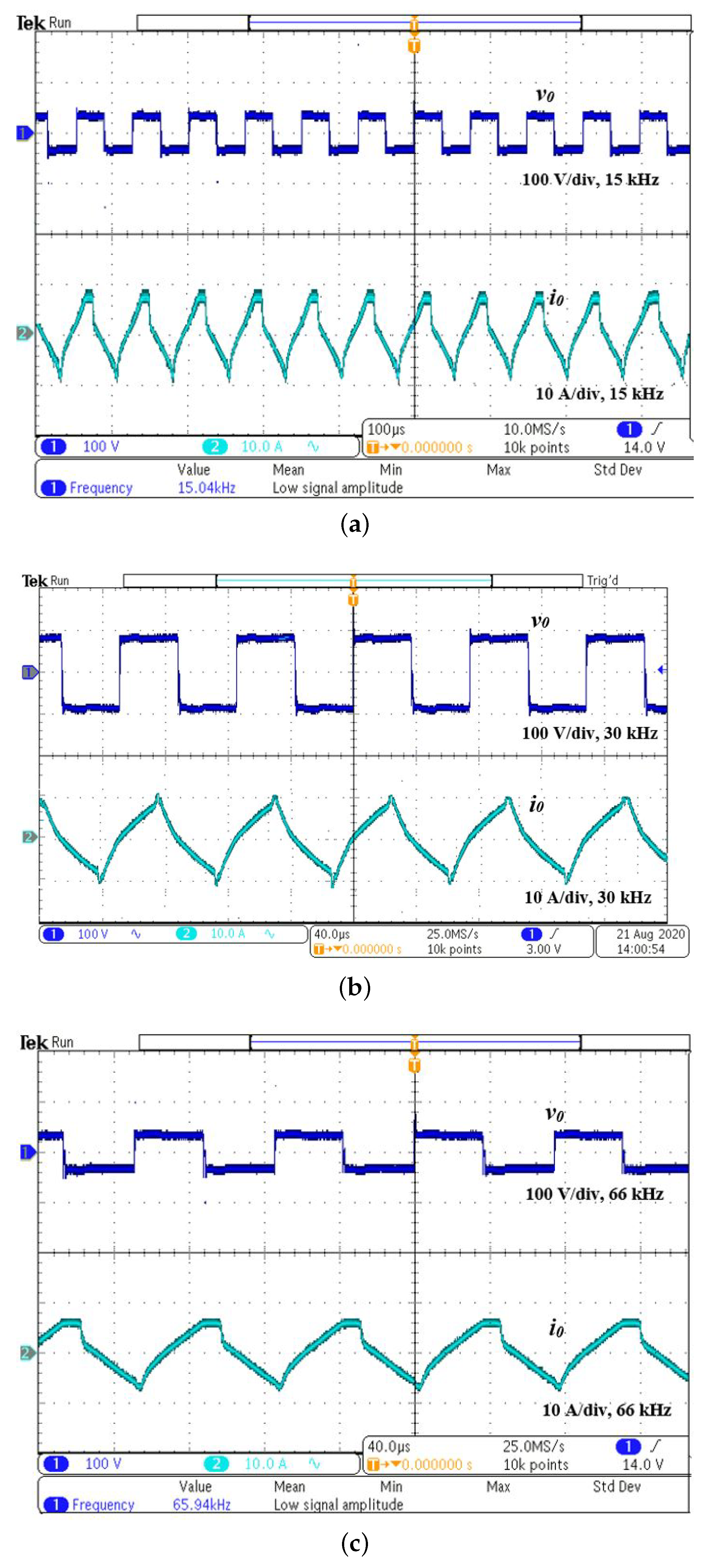
4.2. Variable Frequency Control
The experimental results of variable frequency control are shown in
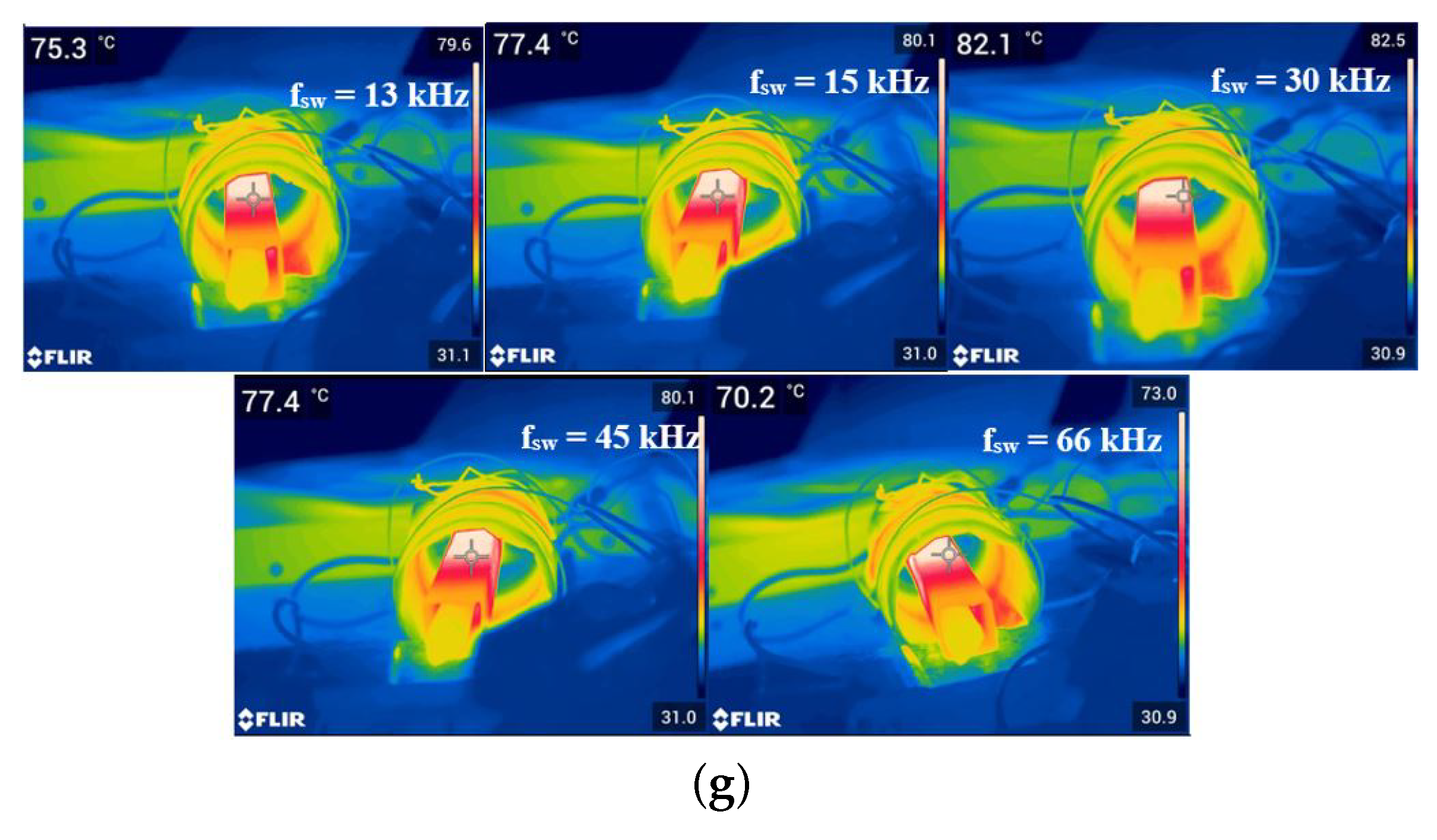
Figure 8. The resonance frequency is 29.5 kHz, and the switching frequency is varied from 13 kHz to 66 kHz to control the output power. The output voltage and the current observed at 15 kHz switching frequency is shown in
Figure 8a. The output voltage and current waveforms for 30 kHz and 66 kHz are shown in
Figure 8b,c, respectively. For a 66 kHz switching frequency, according to Equation (
2),
= 0.82 × 500 = 410 W. The rms value of the current at 66 kHz switching frequency is 6.4 A and
is 6.4
× 10 = 410 W. The input power
is 80 × 6.4 = 512 W. The efficiency for 66 kHz is 80.1%, and it is presented for other switching frequencies in
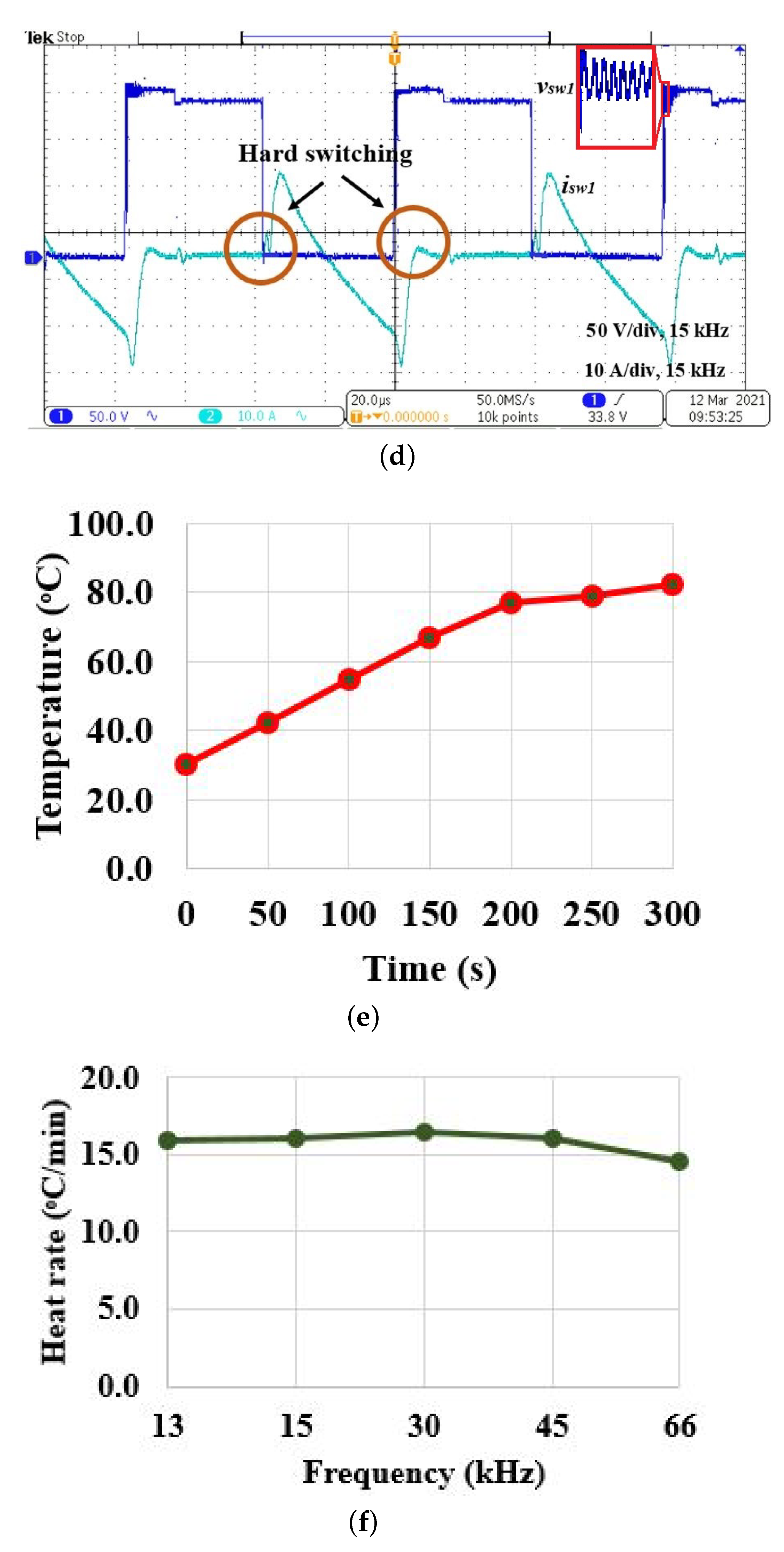
Table 3. It is observed that efficiency is maximum for the resonance condition, and the efficiency is reduced both below and above the resonance frequency due to switching losses. The switch
voltage and current waveforms for 15 kHz are shown in
Figure 8d. It is observed that hard switching is realized as switching frequency is far from the resonance frequency. As the switch is operated in hard switching mode, there exists a ringing effect on the output voltage waveform, which results in more switching loss and stress. Hence, it advisable to operate the inverter switch in resonant operating mode to reduce switching loss and stress. The temperature variation with respect to time is shown in
Figure 8e. The heat rate for various switching frequencies are shown in
Figure 8f and FLIR thermal image for various switching frequencies for a fixed time period (5 min) is illustrated in
Figure 8g. The temperature varies with respect to the switching frequencies.As the switching frequency is varied, the inverter is operated in hard switching mode, which results in more switching loss. In addition, the frequency ringing effect, heat conversion losses, experimental coil design constraints, and capacitor selection restrict the efficiency to 86.9% in real-time implementation.
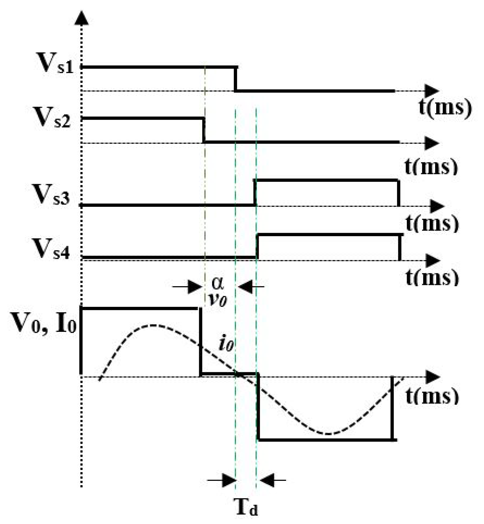
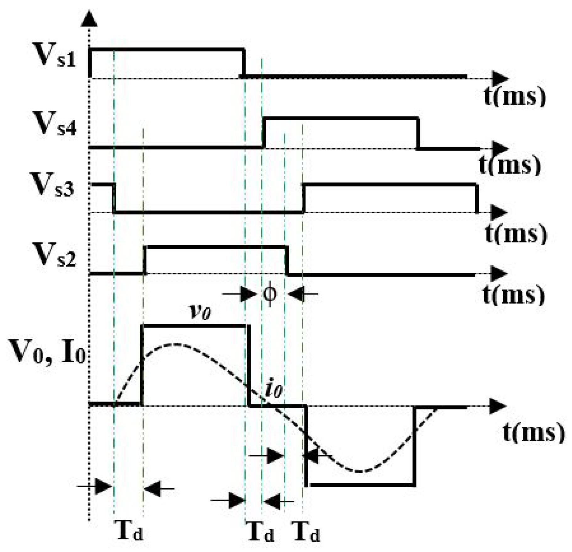
4.3. Phase Shift Control
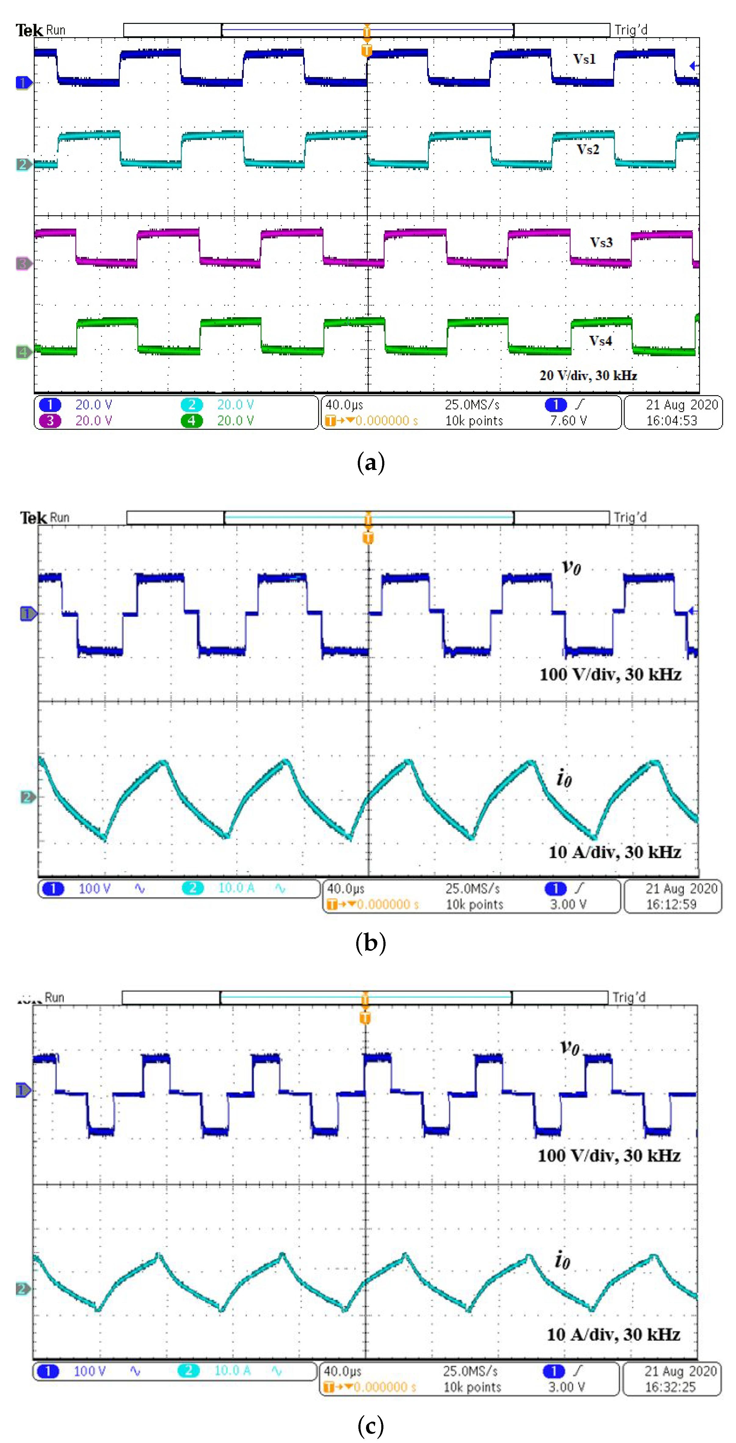
In phase shift control, the switching pulses are shifted with respect to the adjacent leg of the inverter. The variation in rms values of the output voltage and current changes the output power. The experimental results of PSC are shown in
Figure 9. The switching pulses, and output voltage and current waveforms for
= 20
are shown in
Figure 9a,b, respectively. For
= 20
, according to Equation (
5),
is
= 485 W. The rms value of the output current is 6.96 A and
= 6.96
× 10 = 484 W. The input power is 80 × 6.96 = 557 W. The efficiency for various phase angle is given in
Table 4. The output voltage and current waveforms for
= 60
is represented in
Figure 9c. The soft-switching range for phase shift control is shown in
Figure 9d. It is inferred that inverter switches operate in soft switching for
ranging from 0
to 168
. The switch (
) voltage and current waveforms for
= 170
are shown in
Figure 9e, where the switch is operated in hard switching mode. The temperature variation with respect to time is shown in
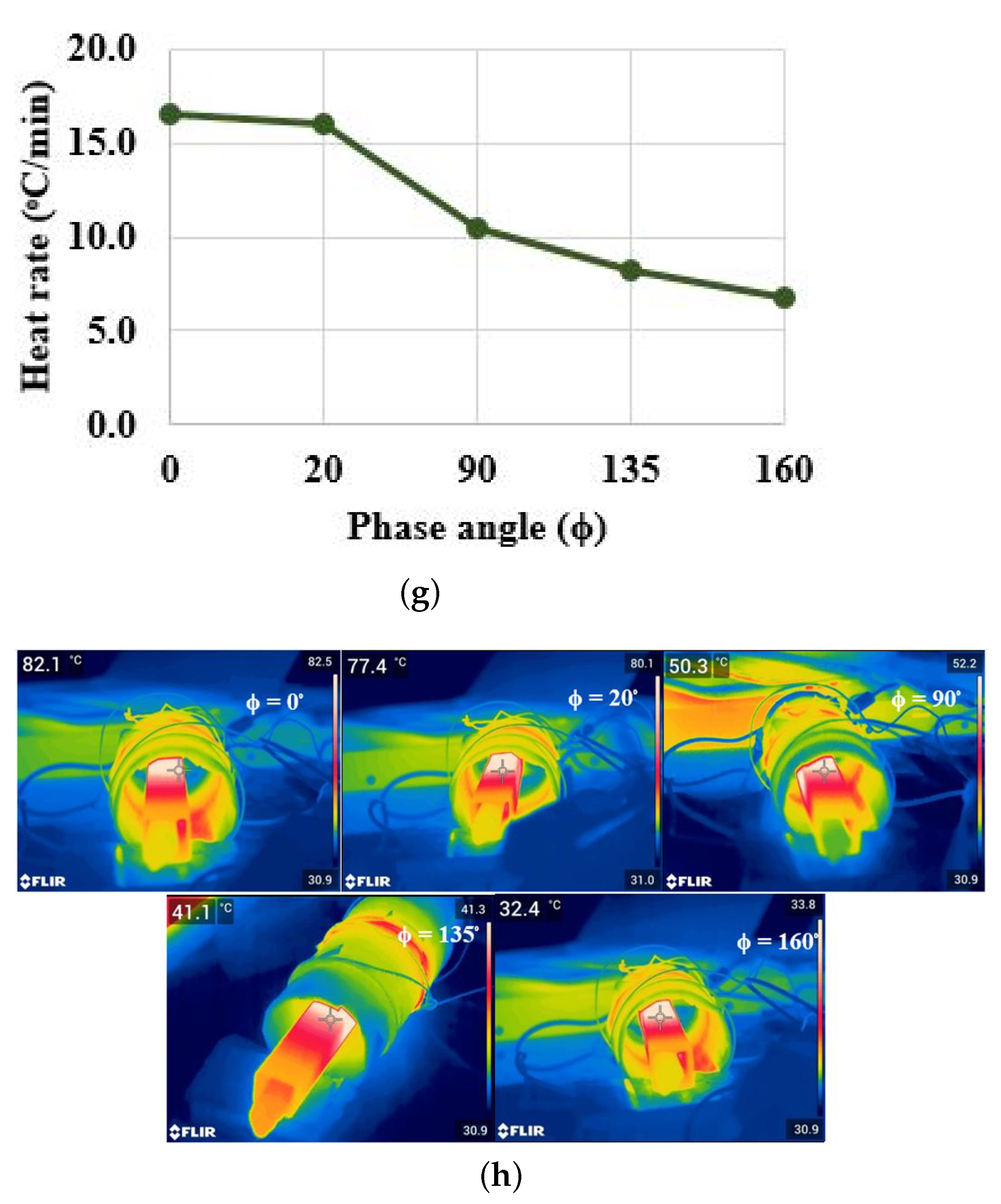
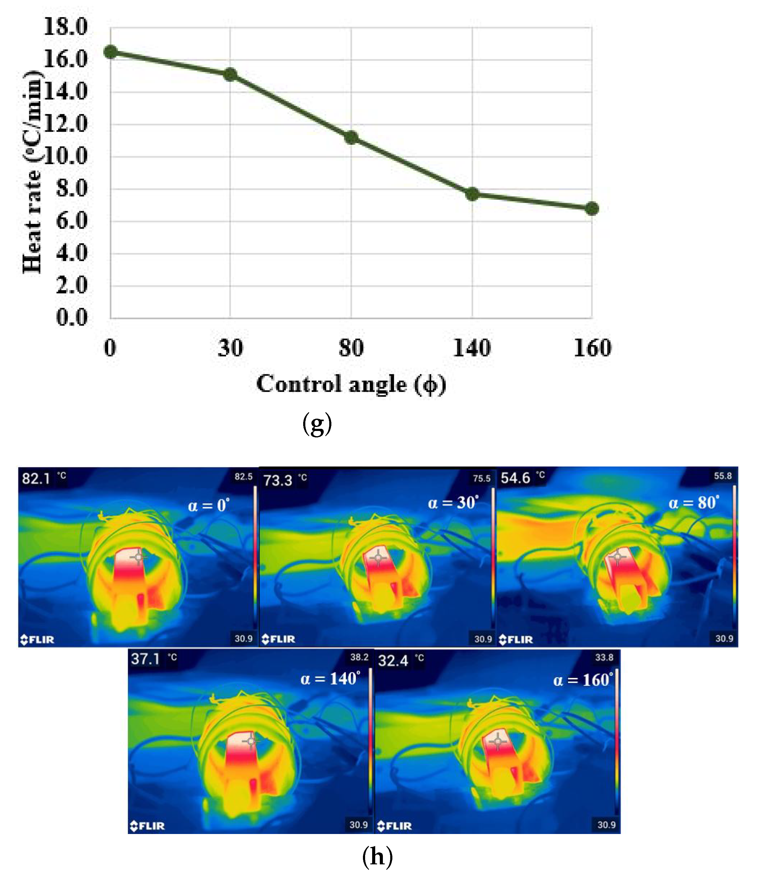
Figure 9f. The heat rate for various phase angles are shown in
Figure 9g and FLIR thermal image for various phase angles for a fixed time period (5 min) is illustrated in
Figure 9h. As the rms value of output voltage varies, the temperature decreases for an increase in phase angle.
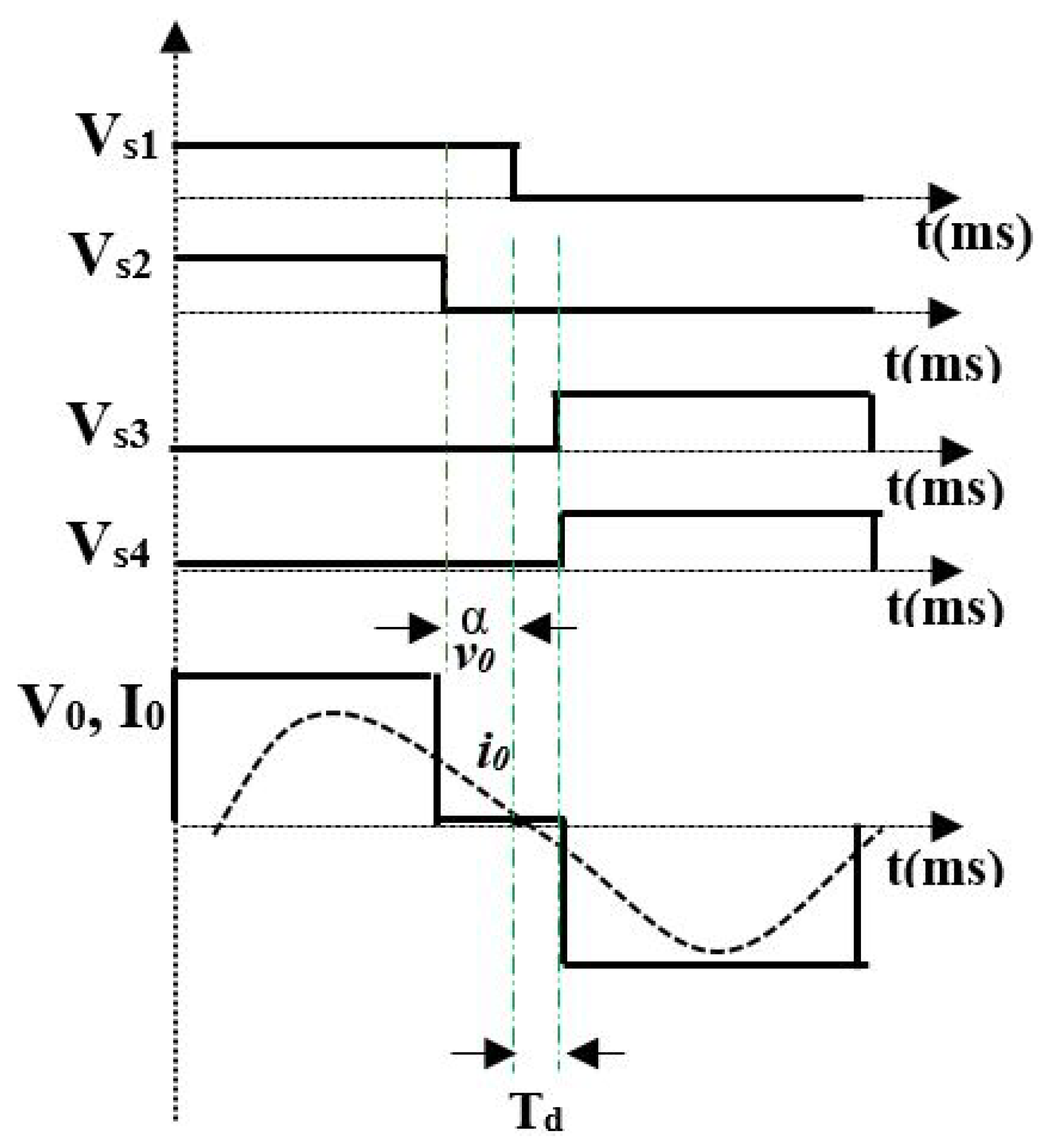
4.4. Asymmetric Duty Cycle Control
The experimental waveforms corresponding to ADC for 30 kHz switching frequency is shown in
Figure 10. The switching pulses and output voltage and current waveforms for
= 30
are shown in
Figure 10a,b. respectively. For
= 30
, according to Equation (
7),
=
= 466.5 W. The rms value of the output current is 6.8 A and
is 6.8
× 10 = 462.4 W. The input power is 80 × 6.7 = 536 W. The efficiency for various control angles is given in
Table 5. The output voltage and current waveforms for
= 140
are shown in
Figure 10c. As there is a dead band for zero crossing of current, the switching losses are reduced by making the inverter operate in soft switching mode. The switch (
) voltage and current waveforms for
= 30
are shown in
Figure 10d, where the switch is operated in soft switching mode. The output voltage is controlled for
ranging from 0
to 165
. The harmonic spectrum for
= 140
is shown in
Figure 10e. It is inferred that there exist even harmonics due to the asymmetric voltage waveform. The variation in temperature with respect to time is shown in
Figure 10f. The heat rate for various control angles is shown in
Figure 10g, and an FLIR thermal image for various phase angles for a fixed time period (5 min) is illustrated in
Figure 10h. As the rms value of the output voltage varies, the temperature decreases with an increase in control angle. The ADC technique holds for a rated power operation and variation in the
results in even harmonics in the output voltage due to asymmetric voltage on either half cycle. This results in a reduction in the efficiency.
4.5. Pulse Density Modulation Control
One of the most efficient control techniques is the pulse density modulation. In this technique, as the switching frequency and its duty cycle are not varied, the soft-switching operation is retained for the entire power variation. In this technique, a low-frequency signal (20 Hz) is compared with high-frequency switching pulses (30 kHz) to produce the pulse pattern in a manner such that, during the on period of a low-frequency signal, high-frequency pulses are applied to the inverter for powering the load. By controlling the density of high-frequency pulses, the output power is controlled.
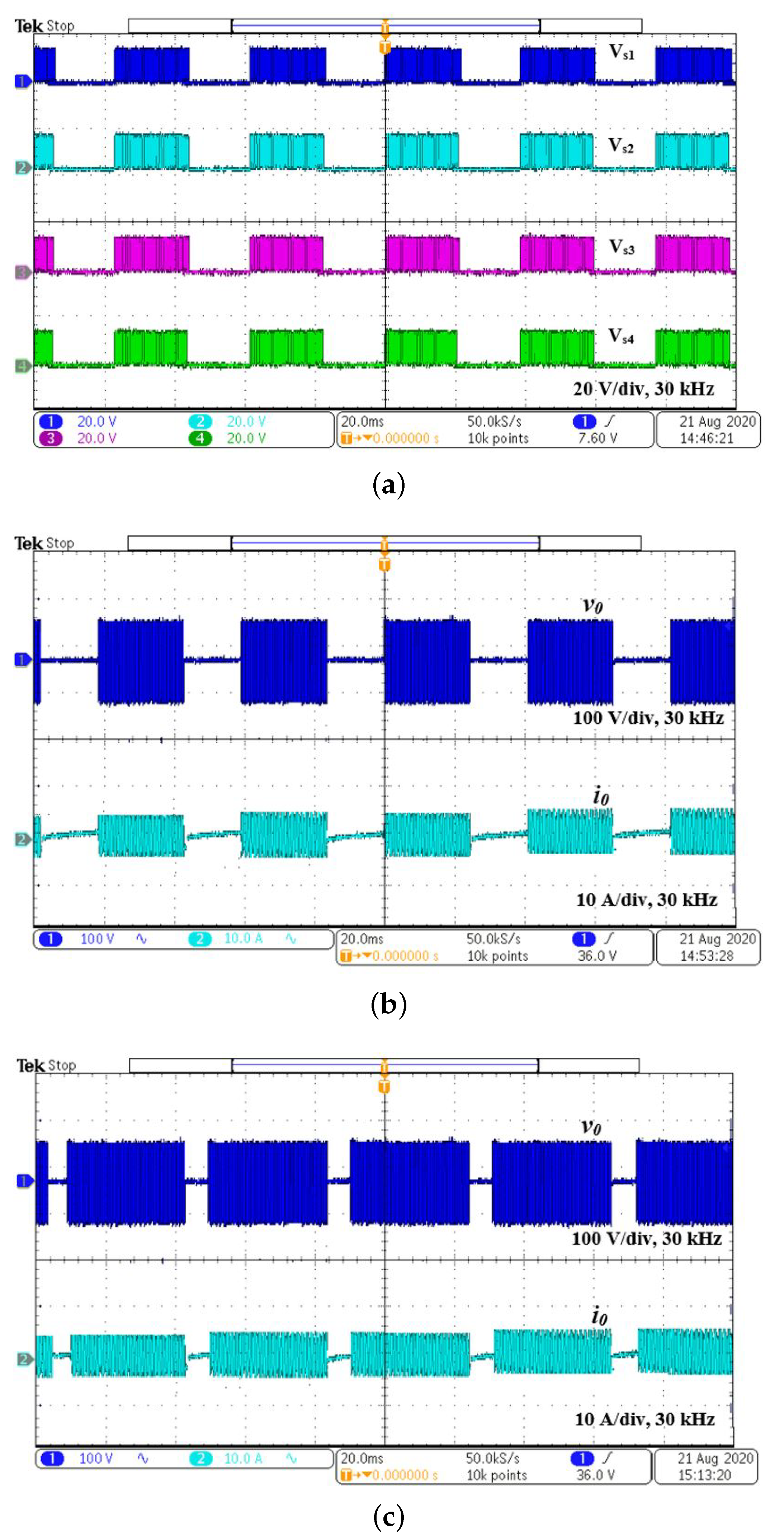
The experimental waveforms for PDM-based control is shown in
Figure 11. The switching pulses and output voltage and the current for
= 60% are shown in
Figure 11a,b, respectively. For 60%
, according to Equation (
9), the calculated
= 500 × 0.6 = 300 W. The rms value of the output current is 5.48 A, and
is 5.48
× 10 = 300 W. The input power is 80 × 4.36 = 348.8 W. The efficiency for various
is given in
Table 6. The output voltage and current waveforms for
= 90% are shown in
Figure 11c. As switching frequency is not varied, resonance is maintained for the entire range of operation. The output power is controlled for the
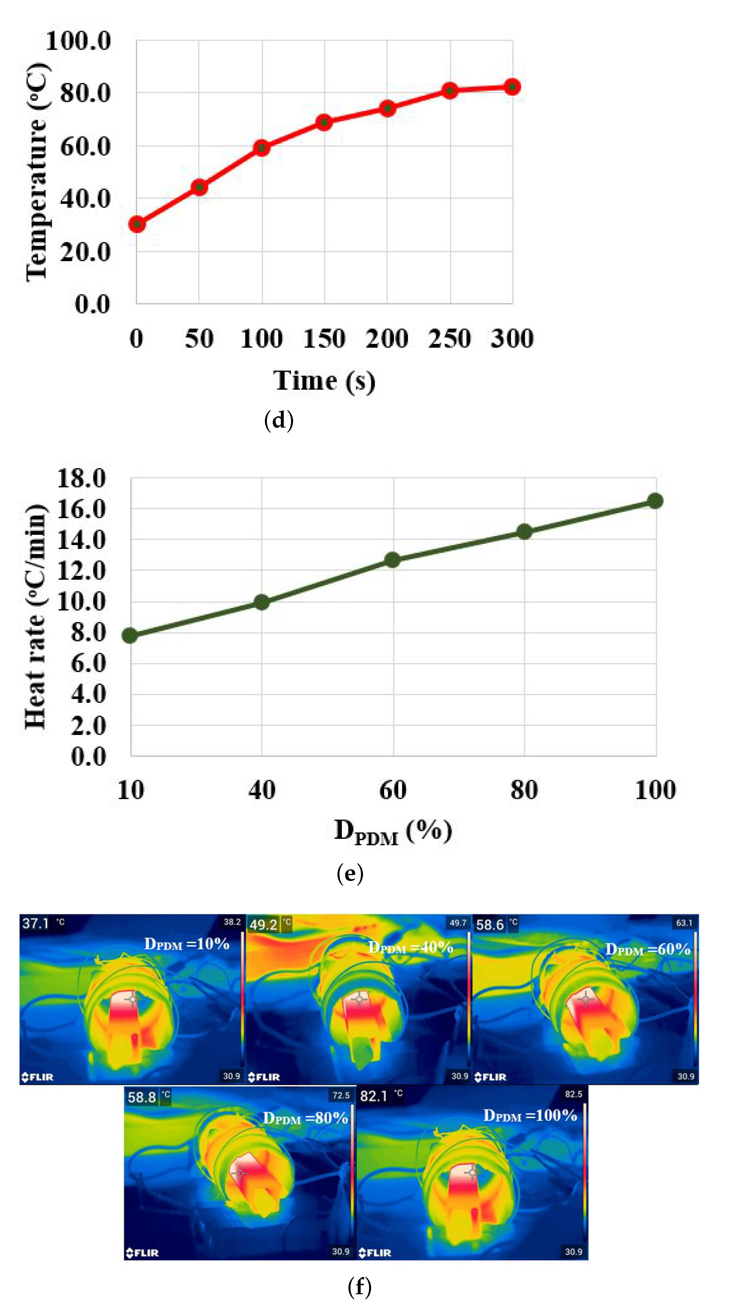
ranging from 0% to 100%. The variation of temperature is shown in
Figure 11d. The heat rate for various
is shown in
Figure 11e and FLIR thermal image for various
for a fixed time period (5 min) is shown in
Figure 11f. The temperature varies with respect to
.


 ,
, 


