Article

Investigation of the Bearing Characteristics of Bolts on a Coal–Rock Combined Anchor Body under Different Pull-Out Rates

1
College of Mining, Guizhou University, Guiyang 550025, China
2
Coal Mine Roadway Support and Disaster Prevention Engineering Research Center, Beijing 100083, China
3
National & Local Joint Laboratory of Engineering for Effective Utilization of Regional Mineral Resources from Karst Areas, Guiyang 550025, China
4
Key Laboratory of Mining Disaster Prevention and Control, Qingdao 266590, China
*
Author to whom correspondence should be addressed.
Energies 2022, 15(9), 3313; https://doi.org/10.3390/en15093313
Submission received: 5 April 2022 / Revised: 15 April 2022 / Accepted: 28 April 2022 / Published: 2 May 2022
(This article belongs to the Special Issue Energy Geotechnics and Geostructures)

Abstract

:
In order to reveal the influence of the pull-out rate on the load-bearing properties of the coal–rock combined anchor body, the mechanical properties and failure characteristics of a coal–rock combined anchor body under different pull-out rates (10, 20, 30, 40, 50 mm/min) were studied using the pull-out test and theoretical analysis. The results show that the bearing capacity of the bolt on the coal–rock combined anchor body improves under a dynamic load, but the load-bearing properties of the coal–rock combined anchor body are different from those of the full rock (coal) anchor body. With the increase in the pull-out rate, the maximum pull-out load of the bolt on the coal–rock combined anchor body increases first, then decreases, and finally tends to be stable. Under the condition of a low drawing rate, the bearing capacity of the coal–rock combined anchor system can be greatly improved, but when the pull-out rate exceeds 20 mm/min, the bearing capacity of the anchor system is reduced. The debonding process of the anchoring section of the coal–rock combined anchor body gradually expands from the beginning section of the anchor to the bottom of the borehole. The coal–rock combined anchor body undergoes time differential development of cracks, and the failure of the coal and rock mass occurs at different times. Its failure process can be divided into three stages: (1) the coal anchor and rock anchor act together; (2) the rock anchor acts alone; and (3) the coal anchor and rock anchor have residual action.

1. Introduction

As the main component of the Yunnan-Guizhou coal base, the only large coal base in South China, the coal resources in Guizhou Province are mainly coal seams having thin and medium thickness less than 2 m [1,2,3], which leads to the coal–rock roadway being widely distributed. Engineering practice shows that the instability and failure of the surrounding rock of the coal–rock roadway mainly depends on the development and expansion of the joints and fissures of this surrounding rock, and the mechanical properties of the coal and rock are determined by the coal–rock interface. An anchor bolt support is a continuous mechanical coupling system that binds the bolt to the rock using an anchoring agent [4]. In the case of a large structural plane (such as the coal–rock interface) on the surrounding rock of the roadway, especially under the condition of mining disturbance, the surrounding rock is unstable and can lead to damage; in this circumstance, the bolt can provide a good reinforcement effect [5,6].
In recent years, domestic and foreign scholars’ research on the load-bearing properties of bolts has mainly focused on the pull-out features of rock specimens with different factors, such as bonding length [7,8,9,10,11,12], borehole water content [13,14,15], temperature [16,17], and pull-out rate [18,19,20,21]. Among these studies, a large amount of research has been carried out on the effect of the pull-out rate on the load-bearing properties of bolts. For example, Du et al. [18] concluded, that with the increase in the pull-out loading rate, the maximum pull-out load increased, the failure of the anchoring interface gradually changed from interval shear failure to overall shear failure, and the failure of the anchoring interface transferred to the interior of the resin grout. Wei et al. [19] found that, with the increase in the pull-out rate, the peak of the pull-out of the anchor body gradually increased, but the increased amplitude slowed with the increase in the loading rate; this increase in the loading rate caused the fracture events to gradually transit to the bottom of the test specimen. Kong et al. [20] concluded that the influence of the pull-out rate on the strength of the anchor can be divided into three influence ranges: strong, medium, and weak. Within the strong influence range, the pull-out rate has an obvious influence on the axial stress and shear stress, which can easily concentrate serious stress in the upper part of the anchor section. Wang et al. [21] considered that the stress of a bolt under a dynamic load is mainly in the form of tensile stress. Zhang et al. [22] considered that the transverse simple harmonic vibration weakens the bond properties of the bolt; in particular, the 40 Hz vibration weakens the anchoring force most significantly. Zhao et al. [23] and Chen et al. [24] found that the pull-out failure strength of the anchor body is positively correlated with the loading rate. Tahmasebinia et al. [25] developed a new analytical simulation technique to evaluate the structural behavior of bolts under dynamic load.
The previous research indicates that the pull-out rate has a great influence on the mechanical properties and failure characteristics of the bolt. In addition, many studies have been conducted on the influence of the loading rate on the mechanical properties and failure characteristics of the coal–rock combined body. For example, Chen et al. [26] concluded that the failure mode and instability mechanism of coal–rock combined specimens are affected by the loading rate, and the failure mode is in the form of plastic failure under a low loading rate, whereas the failure mode is in the form of brittle failure under a high loading rate. Yin et al. [27] found that the uniaxial compressive strength and elastic modulus of the roof and coal pillar structure decrease as the loading rate decreases; however, when the loading rate is 1 × 10⁻⁵ mm/s, the uniaxial compressive strength and elastic show an increasing trend. Gong et al. [28] found that there is a critical loading rate in the uniaxial compression mechanical test of the coal–rock combined body in the range of the low loading rate, and the coal–rock combined body has different mechanical properties in a certain range on both sides of the critical loading rate. Yang et al. [29] concluded that, with the increase in the impact velocity, the maximum dynamic peak stress and peak strain of the coal–rock combined body have an obvious strain rate effect, and the maximum dynamic peak stress increases as an approximate power function. Ma et al. [30] found that the uniaxial compressive strength and elastic modulus of coal–rock combined specimens increase with the increase in the loading rate.
At present, the existing research on the bearing properties of bolts has mostly focused on the rock specimen, and less consideration has been given to the influence of the coal–rock interface and the difference in the coal and rock strength on the bearing capacity of the bolt. There are still deficiencies in the research on the influence of the pull-out rate on the pull-out process and the evolution of the stress characteristic of the bolt on the coal–rock combined anchor body. In view of this, by preparing a coal–rock combined anchor body having a coal height:rock height ratio of 1:1, bolt pull-out tests under pull-out rates of 10, 20, 30, 40, and 50 mm/min were carried out in this study. In-depth examinations were undertaken of the distribution law of axial force and interfacial shear force of the coal–rock combined anchor body under different pull-out rates, the characteristics of anchor and bolt pull-out failure were explored, and the bearing characteristics and failure forms of the coal–rock combined anchor body were determined. This study is expected to provide a useful reference to support bolt design and ground control of coal–rock roadways.

2. Materials and Methods

2.1. Pull-Out Test of Bolts on the Coal–Rock Combined Anchor Body

2.1.1. Test Equipment and Materials

1.
Pull-out system
A QKX-MLB-500 bolt (cable) pull-out creep test system was adopted for the test, which was produced by Qingdao Qiankunxing Intelligent Technology Co., LTD in China. The maximum pull-out load of the test system is 500 kN, the maximum hold time is 72 h, and the vertical loading trip is 0~150 mm [31]. The programmed loading and unloading values and displacement value can be realized through the control system. Furthermore, using the built-in sensors and data acquisition system, all the data can be automatically stored and displayed in real time, and the data can be exported for further processing and analysis.
2.
Strain testing system
The test DH3816N static strain testing system was adopted to monitor the data and to analyze the axial force of the bolt. The test equipment is shown in Figure 1.
3.
Borehole camera
A CXK12 (A) mine intrinsic safety borehole camera was used to observe and analyze the borehole failure characteristics of the anchor body after pull-out, as shown in Figure 2.
4.
Test material
In order to ensure the test conditions were similar to those on site, the right-hand equal strength bolts without longitudinal reinforcement were provided by the mine. The anchor agent was epoxy resin, which was composed of components A (epoxy resin adhesive) and B (curing agent), mixed at 1:1. The shear strength of the epoxy resin can reach more than 20 MPa after 10 min. The test material parameters are shown in Table 1.

2.1.2. Preparation of Anchorage Specimen

1.
Determination of ratio of similar materials for anchoring the surrounding rock
The surrounding rock of the anchor body (coal and rock) in the pull-out test was prepared by mixing river sand, gypsum, lime, and other similar simulation materials, and adding water in a certain proportion. The ratio was determined through the strength ratio test, as shown in Table 2.
2.
Preparation of force-measuring bolt
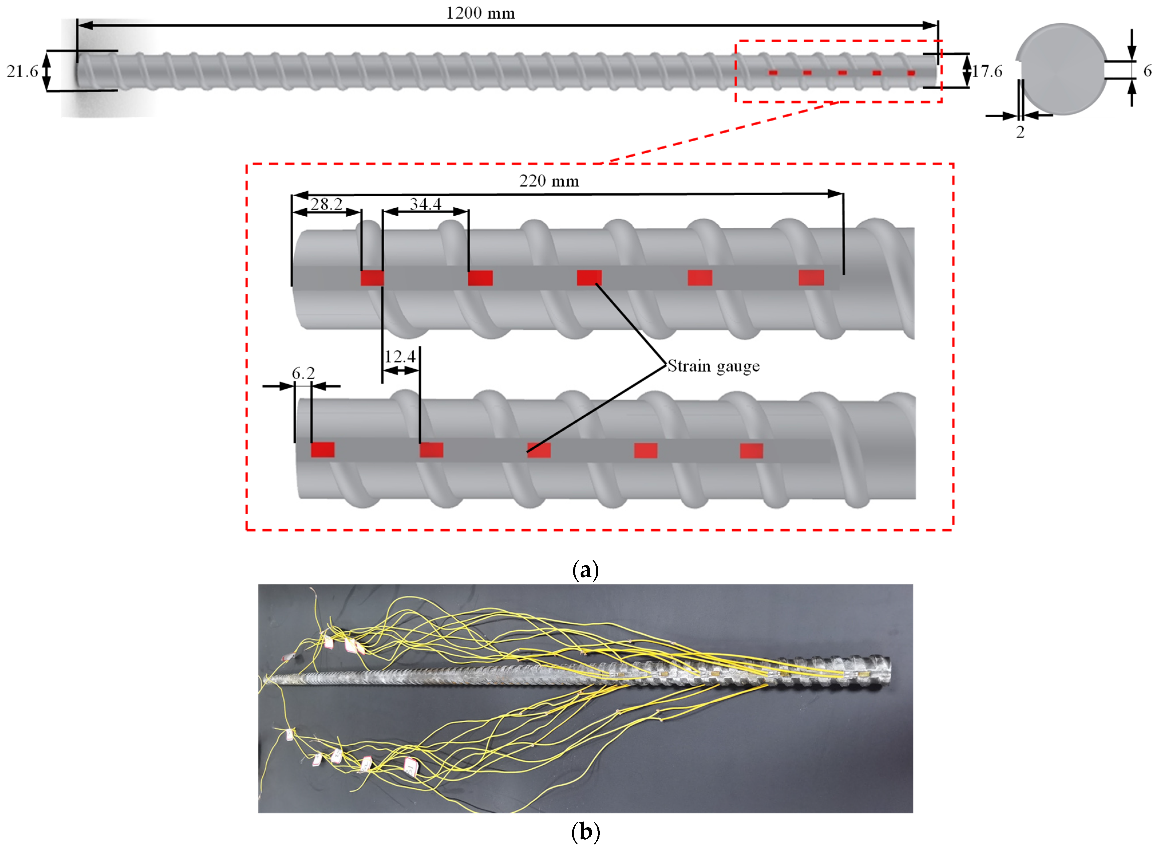
The cutting grooves, which were 6 mm wide, were processed along both sides of the axial direction of the bolt. The grooving surface was polished with fine sandpaper to remove the coating, such as paint, rust, and the oxide layer, and the patch was then scrubbed with absorbent cotton dipped in acetone. A strain gauge labeled A1 was arranged 6.2 mm downward from the end of the bolt on one side of the slot, a strain gauge labeled B1 was arranged 28.2 mm downward from the end of the bolt on the other side of the slot, and a strain gauge was arranged at an interval of 34.4 mm in each slot and numbered successively (A1–A5 on one side and B1–B5 on the other side). A total of 10 strain gauges were arranged on each force-measuring bolt, and the symmetrical spacing was 12.4 mm, as shown in Figure 3. By monitoring the strain gauge during the test, the variation in the axial force at different positions could be obtained, and the distribution law of interfacial shear force along the axial direction of the bolt could be obtained according to Equation (1) [32].
τ i , j + 1 = N i N i + 1 π d Δ x
where τ i , j + 1 is the average shear force between the i and i + 1 points of the interface on the bolt (MPa), N i and N i + 1 are the axial forces of the strain gauge at the i and i + 1 points, respectively, d is the diameter of the bolt (mm), and Δ x is the spacing between strain gauges.
3.
Pull-out specimen preparation
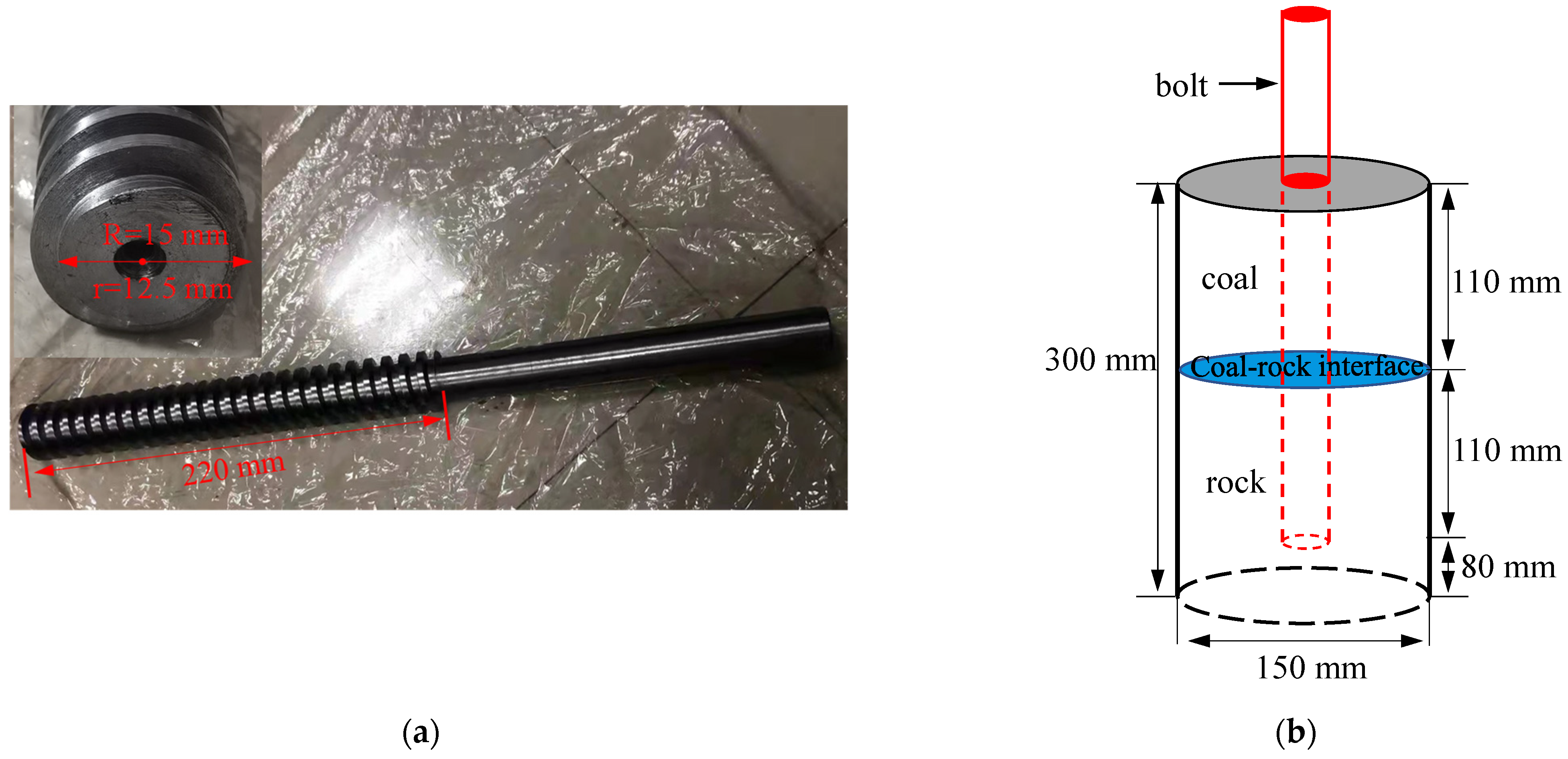
ABS engineering plastic test molds having a size of 150 mm × 300 mm (diameter × height) were used for this test, and material similar to the bottom of the surrounding rock, having a thickness of 80 mm, was laid at the bottom of the test mold to avoid the resin agent from flowing from the bottom of the borehole during the test. After surface painting, a customized steel rod with a thread was placed vertically in the center of the test specimen. Then, the surrounding rock (coal and rock) was used to fill the mold and tamped. Mica powder was sprinkled between the coal and rock to simulate the coal–rock interface. After it became solidified naturally (about half a day), the steel rod was screwed out along the thread to form a simulated borehole. This was placed in a dry environment for natural curing, thereby finally forming an anchor specimen for the pull-out test with a simulated borehole after a period of time. Figure 4 shows the dimensions of the steel rod and anchorage specimen.
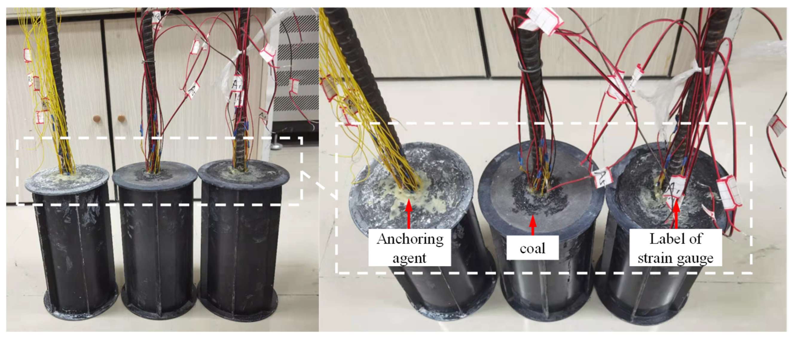
According to the above preparation methods of the force-measuring bolt and pull-out test piece, a total of 5 groups of anchor pull-out test specimens were prepared. After determining the strain gauge line of the prepared force-measuring bolt, the anchor test specimen was inserted vertically, the epoxy resin glue, which was mixed in equal proportion, was injected, and the coal–rock combined anchor body of this test was finally formed after it became solidified and cured naturally for a period of time, as shown in Figure 5.

2.1.3. Test Process

The prepared anchoring pull-out test specimens were successively moved to the test workbench for the pull-out test. The strain test system was connected with the strain gauge of the force-measuring bolt by a 1/4 bridge connection and all measuring points were equilibrated. In order to ensure uniform stress during the pull-out test, the pull-out stroke was pre-programmed, and the pull-out rate was controlled at 10, 20, 30, 40, and 50 mm/min, until the bolts of each specimen were pulled off. The data collection of the pull-out and strain test systems was stopped after the peak value of the pull-out force was reduced to a certain extent. The mining intrinsic safety borehole camera was used to observe each coal–rock combined anchor body after pulling off, with a particular focus on the damage characteristics at the coal–rock interface. The test data were compiled and analyzed after the test was finished.

3. Results

3.1. Effect on Pull-Out Load

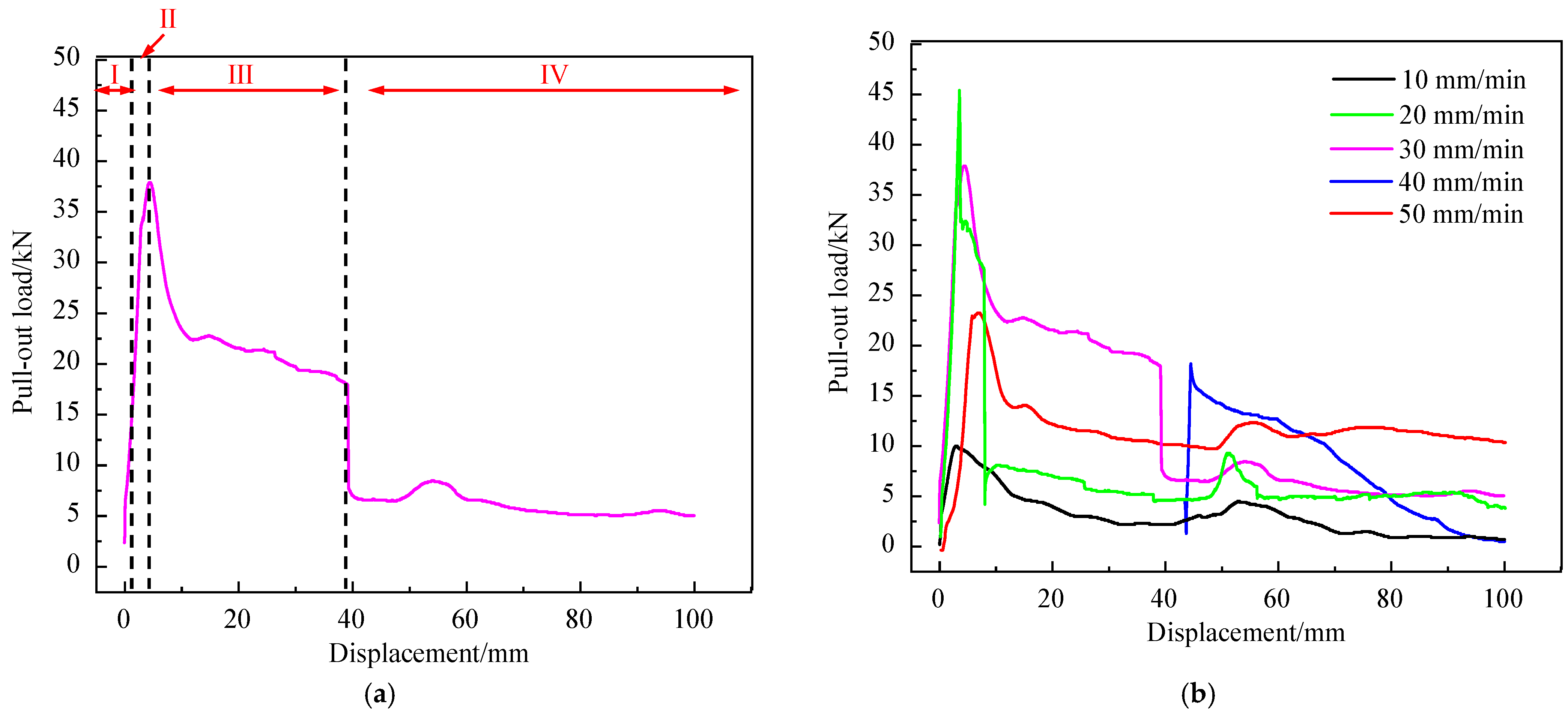
Figure 5 shows the relationship between the pull-out load and pull-out displacement. The main effects of the pull-out rate on the pull-out force are as follows:
  • The general trend in the curve between the pull-out load and displacement at different pull-out rates is basically the same. As shown in Figure 6, it can be divided into four stages [33]: I chemical debonding stage; II microcrack development stage; III shear slip stage; and IV friction slip stage. In the chemical debonding stage, the pull-out bearing capacity of the bolt mainly depends on the chemical bonding force between the bolt and the resin grout, and the pull-out load increases nonlinearly. In the stage of microcrack development, microcracks gradually appear in the anchoring agent and surrounding rock. With the development of microcracks, the bolt pull-out load increases approximately linearly and gradually reaches the maximum pull-out load. In the shear slip stage, shear failure occurs at the anchoring interface, the pull-out load decreases nonlinearly, and the mechanical interlocking effect of the anchorage interface gradually disappears. In the friction slip stage, the pull-out load decreases steadily and the microcracks develop rapidly. When enough microcracks are formed, the anchorage interface is damaged and invalid. At this time, the bolt pull-out load mainly depends on the sliding friction force at the anchorage interface, which is the residual pull-out load of the bolt.
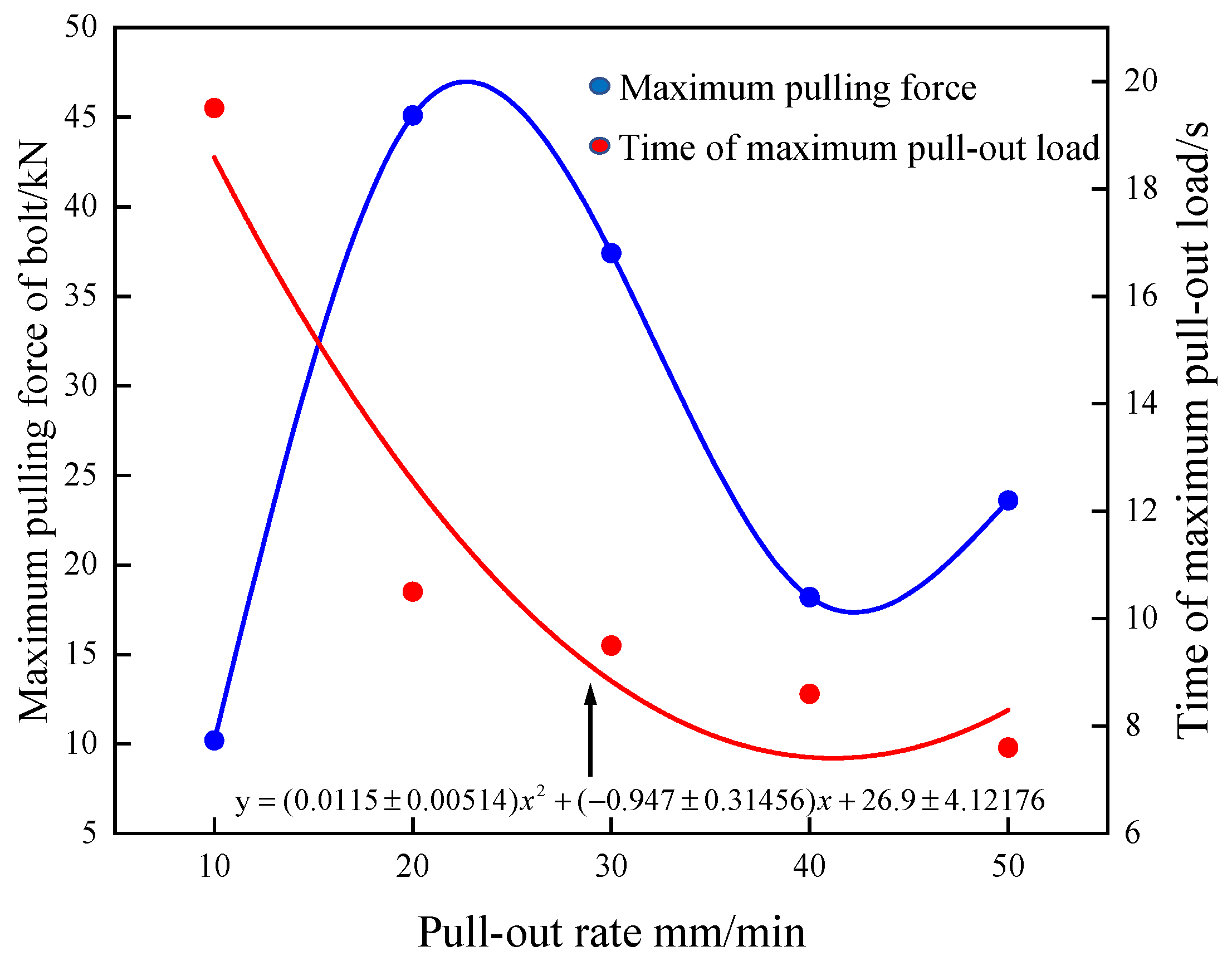
  • With the increase in the pull-out rate, the maximum pull-out load of the bolt first increases, then decreases, and finally tends to be stable. The time to reach the maximum pull-out load decreases gradually with the increase in the pull-out rate, and finally tends to be stable. As shown in Figure 7, when the pull-out rate is 10~20 mm/min, it is at the growth stage. Due to the increase in the pull-out rate, the time is insufficient for the release of the load at the anchorage interface; energy accumulates rapidly and accelerates the failure of the anchorage interface. The pull-out load increases approximately linearly. When the pull-out rate is 20~40 mm/min, it is at the decline stage. Due to the existence of the coal–rock interface and the different media of coal and rock, the coal–rock combined anchor body shows heterogeneity and different strengths [27], resulting in the phenomenon where its elastic modulus and strength gradually decrease with the increase in the pull-out rate, and the pull-out load of the bolt decreases. When the pull-out rate is 40~50 mm/min, the influence of the increase in the pull-out rate on the pull-out load of the bolt is weakened, and the pull-out load of the bolt tends to be stable, which indicates that there is a critical pull-out rate for the coal–rock combined anchor body.

3.2. Effect on Axial Force and Shear Force

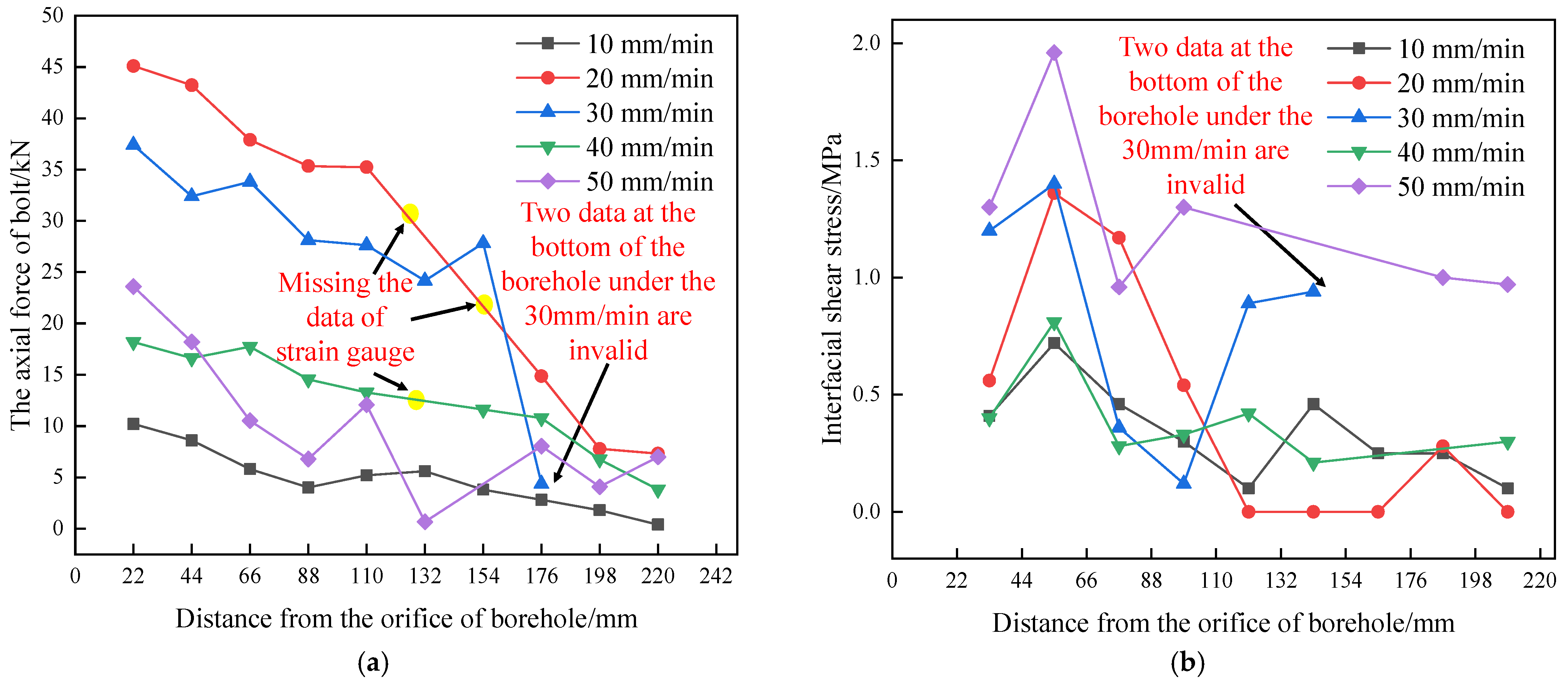
Figure 8 shows the relationship between the maximum pull-out force and the maximum drawing load time under different drawing rates.
It can be seen from Figure 8a that, when the pull-out rate is constant, the axial force is unevenly distributed. As it is close to the bottom of the borehole, the axial force tends to decrease and shows a negative exponential distribution as a whole. When the pull-out rate is 0~20 mm/min, with the increase in the pull-out rate, the axial force from the end of the pull-out section to the middle of the anchor increases significantly, and the axial force changes little from the middle of the anchor section to the bottom. When the pull-out rate is 20 mm/min, the axial force from the end of the anchor section to the middle is greater than that at other pull-out rates. When the pull-out rate is 20~40 mm/min, the axial force from the end of the anchor section to the middle of the anchor section decreases with the increase in the pull-out rate, and there is no obvious change from the middle of the anchor section to the bottom. When the pull-out rate is 40~50 mm/min, the increase in the pull-out rate has little effect on the axial force of the bolt, and the axial force from the end of the anchor section to the bottom is in a certain range. Therefore, it can be said that, when the pull-out rate is 10~20 mm/min, the distribution curve of axial force on the bolt is steeper with the increase in the pull-out rate. When the pull-out rate is 20~40 mm/min, due to the existence of the coal–rock interface and the heterogeneity of the coal–rock combined body, the distribution curve of axial force on the bolt gradually flattens with the increase in the pull-out rate. When the pull-out rate is greater than 40 mm/min, the influence of the increase in the pull-out rate on the axial force of the coal–rock combined anchor body is gradually weakened.
Figure 8b shows the variation characteristics of interfacial shear stress on the bolt under different pull-out rates at the peak time. As can be seen from Figure 8b, when the pull-out rate is constant, the interfacial shear force is unevenly distributed. From the end of the anchor section to the bottom of the anchor section, the force first increases and then decreases, showing an F distribution as a whole. When the pull-out rate is 0~20 mm/min, with the increase in the pull-out rate, the interfacial shear force increases significantly from the end of the pull-out section to the middle of the anchor section, and the interfacial shear force changes little from the middle of the anchor section to the bottom. When the pull-out rate is 20~40 mm/min, the interfacial shear force from the end of the anchor section to the bottom of the anchor section decreases with the increase in the pull-out rate. When the pull-out rate is 40~50 mm/min, the interfacial shear force of the bolt increases with the increase in the pull-out rate. According to the above analysis, it can be concluded that when the pull-out rate is 0~20 or 40~50 mm/min, the increase in the pull-out rate leads to greater concentration and more uneven distribution of the upper interfacial shear stress; this shear force can easily cause the failure of the bolt. When the pull-out rate is 20~40 mm/min, due to the heterogeneity caused by the difference in the strength between the coal and rock, one part of the bolt is in the elastic stage and the other part is in the failure state. The time of shear failure on the bolt in coal and rock is inconsistent. In this section, the interfacial shear force of the bolt decreases with the increase in the pull-out rate.
From the above analysis, it can be seen that, under the influence of dynamic pull-out, the anchor mechanism of the coal–rock combined anchor body is slightly different from that under the condition of rock. In the elastic stage, the greater the pull-out rate, the greater the force on the bolt of the coal–rock combined anchor body. When one part of the bolt is in the elastic stage and the other part of the bolt is in the failure state, the pull-out rate increases and the stress of the bolt on the coal–rock combined anchor body decreases. Under the high pull-out rate, the stress in the upper part of the anchoring section is excessively concentrated, resulting in the breakage of the resin anchorage agent and the matrix around the bolt, and leading to the destruction of the anchor body. The bolt is pulled out alone, and the influence of the pull-out rate on the stress of the bolt begins to weaken. However, the debonding process is the same; that is, there is gradual expansion from the start of the anchorage to the bottom of the borehole, which shows that increasing the anchorage length and the friction coefficient between the borehole wall and the interface of the anchorage agent is still an effective approach for ordinary bolts that pass through the coal–rock interface to resist dynamic pull-out.

3.3. Damage Characteristics of the Coal–Rock Combined Anchor Body

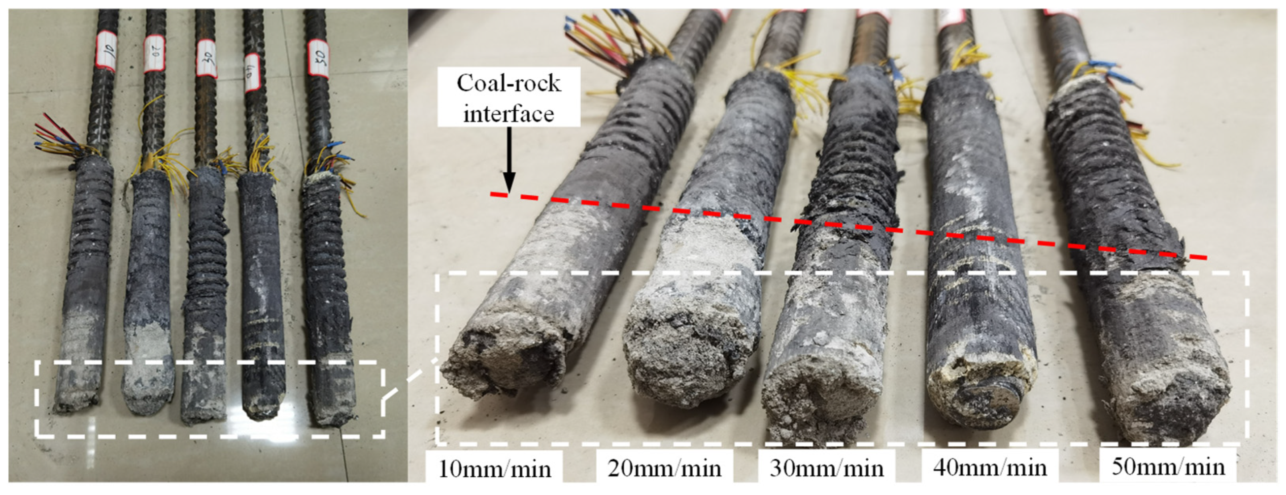
Figure 9 shows the bolt specimen after pull-out. Figure 9 shows the damage characteristics of the coal–rock combined anchor body after pull-out.
It can be seen from Figure 9 that, when the pull-out rate of the bolt is 10 mm/min, after the bolt is pulled out and damaged, part of the surrounding rock is pulled out due to the bonding of the anchorage agent. The thickness of the peeling surrounding rock is low. It can be clearly seen that the peeling surrounding rock at the coal–rock interface is larger than that at other parts, and its integrity is good. When the pull-out rate of the bolt is 20 mm/min, the thickness of the surrounding rock that is pulled out by bolt spalling obviously increases, and the integrity of the peeling surrounding rock at the coal–rock interface is poor. It can be seen that the damage degree at the coal–rock interface is the largest. When the pull-out rate of the bolt is 30 mm/min, the spalling out of the surrounding rock by the bolt is less than that at 20 mm/min, and the spalling out of the surrounding rock has less damage and better integrity. When the pull-out rate of the bolt is 40 mm/min, compared with that at 30 mm/min, the peeling out of the surrounding rock is still reduced, but the degree is small. Because the coal body is on the top during pull-out, the surrounding rock pulled out of the rock is dyed black, which indicates that the degree of damage of the coal body on the interior of the coal–rock combined anchor body is small. This is because the increase in the pull-out rate shortens the time for the coal and rock to reach the critical failure state; because the duration of pulling out on the bolt is short, the anchor body is damaged instantaneously, resulting in the surrounding rock falling off. As a result, the damage degree of the surrounding rock on the interior of the anchor is weakened and the failure interface is relatively smooth. When the pull-out rate of the bolt is 50 mm/min, compared with the case when the pull-out rate is 40 mm/min, the integrity of the surrounding rock and the thickness of the peeling surrounding rock are little different, and the failure interface is relatively smooth.
Figure 10a shows the damage characteristics of the coal–rock combined anchor specimens; it can be seen that, under the pull-out rate of 10 mm/min, the specimen is relatively complete, the failure surface is relatively smooth, and there is no failure on the surface. Under the pull-out rate of 20 mm/min, the integrity of the specimen is poor, the “X” fracture appears on the surface, the crack appears on the PVC test mold, and the part of the coal on the specimen is greatly damaged. Under the pull-out rate of 30 mm/min, the integrity of the specimen is also poor, there are still “X” cracks on the surface, there are small cracks in the PVC test mold, and the damage degree of the coal on the specimen is still large, although it is smaller than that of 20 mm/min. Under the pull-out rate of 40 mm/min, the test specimen is relatively complete without fractures on the surface, the PVC test mold is relatively complete without cracks, the damage of the coal is small, and the anchorage interface is relatively smooth after pulling off. Under the pull-out rate of 50 mm/min, there is little difference in the test specimen compared to that of 40 mm/min. There are no fractures on the surface of the PVC test mold and the test specimen. It can be clearly observed that there is no major damage in the borehole after pulling off.
Figure 10b shows the results of borehole peeping. From the analysis, it was found that, under the pull-out rate of 10 mm/min, the damage degree of the borehole is small, and the damage can be obviously seen on the coal–rock interface, whose damage degree is greater than that of other parts of the borehole. Under the pull-out rate of 20 mm/min, the damage degree of the borehole increases obviously, and the damage on the coal–rock interface is large. The whole borehole is divided into two parts with the difference in damage degree. Coal, which is the upper part, has large cracks due to its low strength and high damage degree. Although the failure section of the lower rock part is uneven and rough, the damage is relatively small. Under the pull-out rate of 30 mm/min, compared with the pull-out rate of 20 mm/min, the degree of borehole damage is reduced, but it is still divided into two parts, which are the upper and lower parts of the coal–rock interface. There are still large cracks in the upper coal body, the surrounding rock is broken, the lower rock body is somewhat smooth, and the degree of borehole damage is weakened as a whole. Under the pull-out rate of 40 mm/min, the borehole becomes smooth, although the coal–rock interface is clearly visible, there is no major damage, the integrity of the surrounding rock is good, and there is no crack, which is consistent with the failure of the bolt specimen. Under the pull-out rate of 50 mm/min, compared with the pull-out rate of 40 mm/min, there is no significant change, and the integrity of the surrounding rock is good, with the exception that there is a little damage on the coal–rock interface; in addition, the wall of the borehole is smooth, and there is no cracking or obvious damage in the surrounding rock.
According to the above analysis, on the whole, the damage degree of the coal is significantly greater than that of rock, and there is a large degree of damage on the coal–rock interface. The failure mode of the bolt that passes through the coal–rock interface under different pull-out rates is different from that in the whole rock (coal) specimen. The specific performance can be characterized as follows: with the increase in the pull-out rate, the damage degree of the anchor first increases, then decreases, and finally tends to be stable. This is consistent with the conclusion of the data analysis of the pull-out test.

4. Discussion

4.1. Time Differential Development of Cracks on the Coal–Rock Combined Anchor Body

Existing research shows that [28], when the loading rate is too low, the failure of coal–rock combined body is mainly due to the failure of coal. When the loading rate is high, the failure of the coal–rock combined body occurs because the coal and rock break together, but the fragmentation of coal is more severe. Due to the different strengths of coal and rock, the bolt is finally in the pulled out state. Combined with the failure process of the pull-out test of the bolt on the coal–rock combined anchor body, under the pull-out rates of 20 and 30 mm/min, the partial failure of coal causes cracks in the PVC test model with a crackling sound, but the pull-out load is still in the growth stage (Figure 11). This shows that the coal is damaged at this stage, but the rock still has bearing capacity. That is, there is a difference in the times of the destruction of coal and rock in the pull-out process of the coal–rock combined anchor body, and the coal–rock combined anchor body undergoes time differential development of cracks. The failure of the coal–rock interface is particularly obvious. In the process of the pull-out failure on the bolt, the existence of the coal–rock interface plays an important role in the bolt’s overall tension shear failure.
Therefore, the pull-out process of the bolt on the coal–rock combined anchor body can be divided into three stages with the increase in the pull-out load: ① The stage during which the coal anchor and rock anchor act together. That is, the anchorage interfaces of coal and rock are not damaged. In this stage, the maximum pull-out load of the anchor is mainly due to the joint action of the anchorage interface force between the coal and rock. With the increase in the pull-out load, the local strain of the anchorage interface increases. ② The stage during which the rock anchor acts alone. That is, in the stage when the anchoring interface of the coal is damaged and the anchoring interface of the rock is not damaged, the maximum pull-out load of the anchor bolt is mainly affected by the residual strength of the coal after failure and the stress of the anchoring interface of rock. With the increase in the pull-out load, it finally reaches the critical failure state of the anchoring interface of the rock. ③ The stage during which the coal anchor and the rock anchor have residual action. That is, the anchorage interfaces of the coal and rock are damaged. In this stage, because the pull-out load exceeds the bearing capacity of the coal–rock combined anchor body, the anchorage interfaces of the coal and rock are damaged. The maximum pull-out load of the anchor body is mainly affected by the residual strength of the coal–rock combined anchor body.

4.2. Mechanical Properties of the Coal–Rock Combined Anchor Body under Different Pull-Out Rates

Before analyzing the mechanical model of the coal–rock combined anchor body, the following assumptions are made: (1) the strength of coal–rock combined body obeys the Mohr–Coulomb strength criterion; (2) the coal–rock combined body is isotropic.
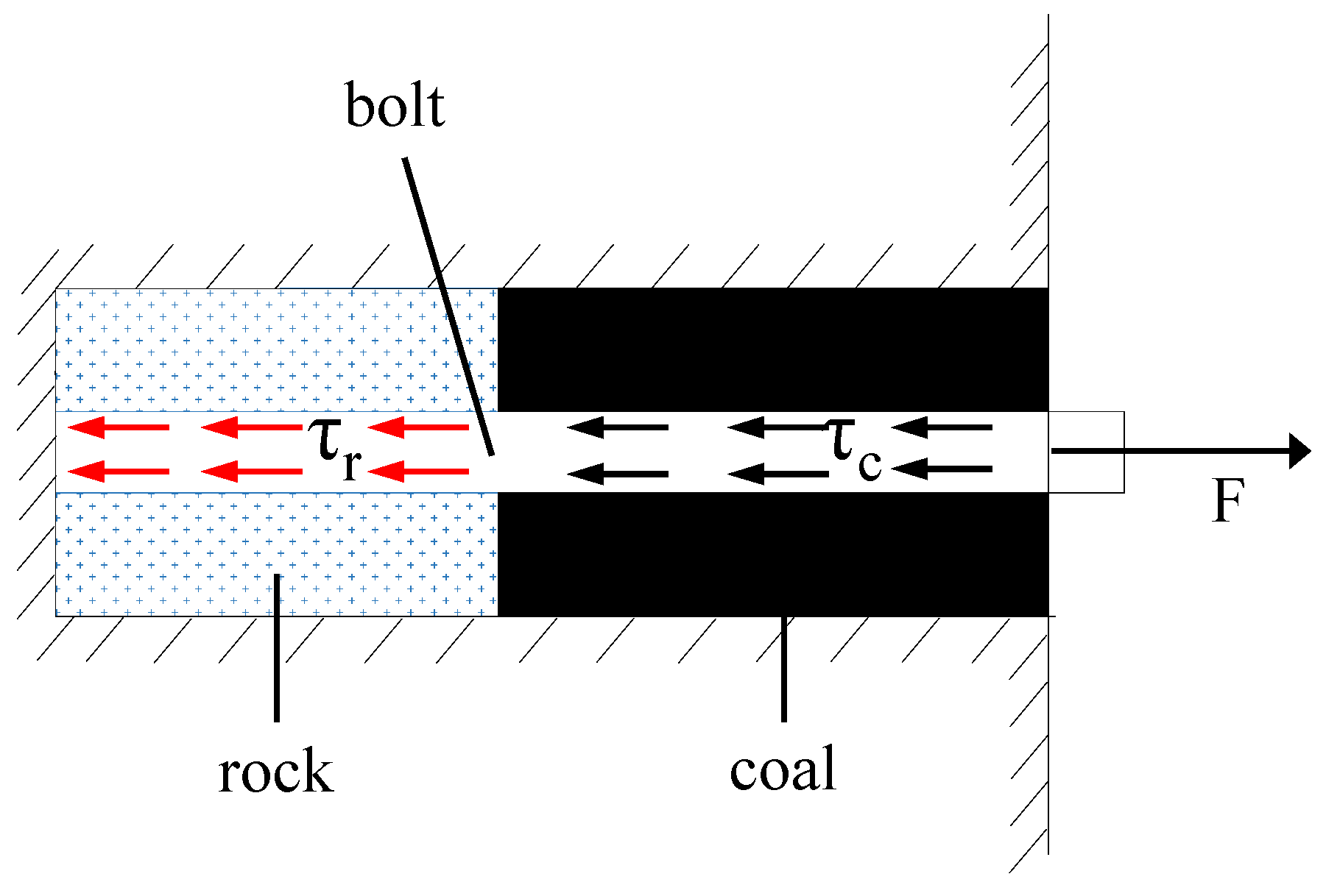
It can be seen from Figure 12 that the maximum shear stress of the anchorage interface under a pull-out load of τ m can be expressed as:
τ m = τ c + τ r + τ sin φ
where τ c is the maximum shear stress on the anchorage interface of the coal and τ r is the maximum shear stress at the anchorage interface of the rock.
In the process of pulling out, it can be considered that the mechanical behavior of the anchorage interfaces of coal and rock satisfy the Mohr–Coulomb strength criterion [34], as shown in Figure 13. Therefore, the maximum shear stress at the anchorage interfaces of coal and rock under pull-out load can be expressed as:
τ c = C c + ( σ cn 0 + σ cn a ) tan φ 1
where C c is the cohesion of the anchorage interface of coal; σ cn 0 is the initial normal stress of the anchorage interface of the coal; σ cn a is the maximum additional normal stress of the anchorage interface of the coal; and φ 1 is the friction angle of the anchorage interface of the coal.
τ r = C r + ( σ rn 0 + σ rn a ) tan φ 2
where C r is the cohesion of the anchorage interface of rock; σ cn 0 is the initial normal stress of the anchorage interface of rock; σ rn a is the maximum additional normal stress at the anchorage interface of rock; and φ 2 is the friction angle of the anchorage interface of rock.
According to the principle of equivalent stiffness, the additional normal stress, τ ( x ) , can be expressed as:
σ n a = k ε
where is the normal restraint stiffness of the anchor body, where k = E b ( 1 + μ ) , E is the elastic modulus of the anchor body-confined medium, μ is the Poisson’s ratio of the confined medium of the anchor body, and b is the radius of the borehole, m; and ε is the local strain at the anchorage interface.
The maximum shear stress of the anchorage interface can be obtained as [35]:
τ m = p m π d b l
where p m is the maximum pull-out load, N; d b is the diameter of bolt, m; l is the bonding length, m. Combined with Equations (2)–(6), the maximum pull-out load can be expressed as:
p max = π d b l [ C c + ( σ cn 0 + σ cn a ) tan φ 1 + C r + ( σ rn 0 + σ rn a ) tan φ 2 ]
The other parameters remain unchanged, and the local strain at the anchorage interface directly determines the maximum pull-out load. With the increase in the pull-out rate, the local strain of the anchorage interface increases, so the maximum pull-out load of the bolt also increases. However, the increase in the pull-out rate accelerates the failure of the anchorage interface. Due to the different strength and the difference in the stiffness between the coal and rock, the strain of the coal relative to that of rock is large under the same force, which can easily cause failure. Therefore, with the increase in the pull-out rate, the difference in the time of failure on the anchorage interfaces of coal and rock will become more and more obvious; this is consistent with the characteristics of the time differential development of cracks of the coal–rock combined anchor body in the test process.
It is also consistent with the phenomenon in the laboratory test, which shows that the bearing characteristics of the bolt on the coal–rock combined anchor body under different pull-out rates are different from those of whole rock (coal). The specific performance can be characterized as follows: with the increase in the pull-out rate, the bearing capacity of the bolt on the coal–rock combined anchor body first increases, then decreases, and finally tends to be stable.

5. Conclusions

  • Under the condition of a dynamic load, the bearing characteristics of the coal–rock combined anchor body are different from those of rock. With the increase in the pull-out rate, the maximum pull-out load of a bolt passing through the coal–rock interface increases first, then decreases, and finally tends to be stable. A low pull-out rate can greatly improve the bearing capacity of the anchorage system. Across the coal–rock interface, the bearing capacity of the coal–rock combined anchor system can be greatly improved, but when the pull-out rate exceeds 20 mm/min, the bearing capacity of the anchor system will be reduced.
  • Under different pull-out rates, the debonding process of a bolt passing through the coal–rock interface is the same as that in rock. The debonding process of the anchoring section of the coal–rock combined anchor body gradually expands from the beginning section of the anchor to the bottom of the borehole. Increasing the anchoring length and the friction coefficient between the borehole wall and the anchoring agent interface is an effective way to improve the dynamic load resistance of a bolt passing through the coal–rock interface.
  • The coal–rock combined anchor body undergoes time differential development of cracks, and the failure of the coal and rock mass occurs at different times. The failure process can be divided into three stages: (1) the coal anchor and rock anchor act together; (2) the rock anchor acts alone; and (3) the coal anchor and rock anchor have residual action.
  • In this test, the anchor-surrounding rock was equivalent to the test model constraint, and the interfacial effect of the coal–rock interface was not considered. In the future, the bearing performance of the bolt on the coal–rock combined anchor body under conditions approaching the real confining pressure should be further studied.
  • In the current work, the bearing performance of the bolt under different pull-out rates was studied, and it was found that the coal–rock combined anchor body underwent time differential development of cracks. In the future, combined with different coal rock interface inclinations and differences in the coal rock height ratio, it would help to propose a theoretical basis for the anchorage support of the coal–rock roadway under the influence of dynamic pressure.

Author Contributions

Conceptualization, P.Z. and L.G.; methodology, P.Z. and L.G.; software, X.Z. and P.L. (Pengze Liu); validation, X.K., L.G. and P.Z.; formal analysis, P.Z.; investigation, P.Z., L.G., X.K., Z.M. and S.H.; resources, L.G.; data curation, P.Z.; writing—original draft preparation, P.Z.; writing—review and editing, L.G.; visualization, L.G. and P.Z.; supervision, P.Z.; project administration, P.Z.; funding acquisition, L.G., Y.W. and P.L. (Ping Liu). All authors have read and agreed to the published version of the manuscript.

Funding

This paper is financially supported by the National Natural Science Foundation of China (No. 52004073 and No. 52064009); The Science and Technology Support Plan of Guizhou Province (No. Qian Ke He Zhi Cheng [2021] General 400); The Science and Technology Foundation of Guizhou Province (No. Qian Ke He Ji Chu [2020]1Y216); Guizhou Science and Technology Plan Project (Qianke Science Foundation [2020]1Z047); The Scientific research project for talents introduction of Guizhou University (No. Gui Da Ren Ji He Zi (2020) No. 42), and The Cultivation project of Guizhou University (No. Gui Da Pei Yu [2019] No. 27); The Open Project Fund of Key Laboratory of Mining Disaster Prevention and Control (No. SMDPC202106) during the research.

Institutional Review Board Statement

The study did not require ethical approval.

Informed Consent Statement

Informed consent was obtained from all subjects involved in the study.

Data Availability Statement

The data used to support the conclusions of this study are available from the corresponding author upon request.

Conflicts of Interest

The authors declare that there is no conflict of interest regarding the publication of this paper.

References

  1. Cheng, L.X.; Zhang, H.; Jiang, P.F.; Cai, R.C.; Li, B.B. Mechanical properties and experimental study on reaming anchor in soft coal and rock mass. J. Min. Saf. Eng. 2019, 36, 1153–1160. [Google Scholar]
  2. Yu, W.J.; Feng, T.; Wang, W.J.; Wang, P.; Yuan, C.; Guo, G.Y.; Du, S.H. Support problems and solutions of roadway surrounding rock for thin coal seams under complex conditions in Southern China. J. China Coal Soc. 2015, 40, 2370–2379. [Google Scholar]
  3. Yu, W.J.; Wu, G.S.; Liu, H.; Wang, P.; An, B.F.; Liu, Z.; Huang, Z.; Liu, F.F. Deformation characteristics and stability control of soft coal-rock mining roadway in thin coal seam. J. China Coal Soc. 2018, 43, 2668–2678. [Google Scholar]
  4. Aghchai, M.H.; Maarefvand, P.; Rad, H.S. Analy-tically determining bond shear strength of fully grouted rock bolt based on pullout test results. Period. Polytech.-Civ. Eng. 2020, 64, 212–222. [Google Scholar]
  5. Liu, C.C.; Li, Y.Z. Research progress in bolting mechanism and theories of fully grouted bolts in jointed rock masses. Chin. J. Rock Mech. Eng. 2018, 37, 1856–1872. [Google Scholar]
  6. Kang, H.P.; Lin, J.; Wu, Y.Z.; Cheng, P.; Meng, X.Z.; Ren, S. Mechanical performances and compatibility of rock bolt components. J. China Coal Soc. 2015, 40, 11–23. [Google Scholar]
  7. Xiao, T.Q.; Li, H.M.; Li, H.Y.; Wang, M. Pull-out properties of bolt with different anchorage length. J. Min. Saf. Eng. 2017, 34, 1075–1080. [Google Scholar]
  8. Wang, H.T.; Wang, Q.; Wang, F.Q.; Li, S.C.; Wang, D.C.; Ren, Y.X.; Guo, N.B.; Zhang, S.G. Mechanical effect analysis of bolts in roadway under different anchoring lengths and its application. J. China Coal Soc. 2015, 40, 509–515. [Google Scholar]
  9. Du, Y.L.; Feng, G.R.; Kang, H.P.; Zhang, Y.J.; Zhang, X.H. Investigation on the pull-out bearing characteristics of bolts with different bond lengths. J. Min. Strat. Control Eng. 2021, 3, 5–12. [Google Scholar]
  10. Li, C.C.; Kristjansson, G.; Høien, A.H. Critical embedment length and bond strength of fully encapsulated rebar rockbolts. Tunn. Undergr. Space Technol. 2016, 59, 16–23. [Google Scholar] [CrossRef] [Green Version]
  11. Thenevin, I.; Blanco-Martin, L.; Hadj-Hassen, F.; Schleifer, J.; Lubosik, Z.; Wrana, A. Laboratory pull-out tests on fully grouted rock bolts and cable bolts: Results and lessons learned. J. Rock Mech. Geotech. Eng. 2017, 9, 843–855. [Google Scholar] [CrossRef]
  12. Hoien, A.H.; Li, C.C.; Zhang, N. Pull-out and Critical Embedment Length of Grouted Rebar Rock Bolts-Mechanisms When Approaching and Reaching the Ultimate Load. Rock Mech. Rock Eng. 2021, 54, 1431–1447. [Google Scholar] [CrossRef]
  13. Hu, B.; Kang, H.P.; Lin, J.; Cai, J.F. Influence of Water on Anchorage Properties of resin Bolt. J. Min. Saf. Eng. 2013, 18, 44–47,51. [Google Scholar]
  14. Zhou, H.J.; Li, G.C.; Cui, G.J.; He, J.T.; Sun, C.L.; Du, L.L. Research on Weakening Performance of Anchor Bolt by Drilling Water. Saf. Coal Mines 2018, 49, 54–57. [Google Scholar]
  15. Kim, H.J.; Kim, K.H.; Kim, H.M.; Shin, J.H. Anchorage mechanism and pullout resistance of rock bolt in water-bearing rocks. Geomech. Eng. 2018, 15, 841–849. [Google Scholar]
  16. Hu, B.; Kang, H.P.; Lin, J.; Cai, J.F.; Jing, P.F. Study on Influence of Temperature on Anchorage Performance of Resin Anchored Bolt. J. Min. Saf. Eng. 2012, 29, 644–649. [Google Scholar]
  17. Wang, J.Y.; Guo, J.M.; Mi, J.F.; Zhang, Y.; Shi, E.R. Influence of the temperature on the gel time of the capsules in rock bolting system. J. China Coal Soc. 2008, 06, 619–622. [Google Scholar]
  18. Du, Y.L.; Feng, G.R.; Kang, H.P.; Zhang, Y.J.; Zhang, X.H. Effects of different pull-out loading rates on mechanical behaviors and acoustic emission responses of fully grouted bolts. J. Cent. South Univ. 2021, 28, 2052–2066. [Google Scholar] [CrossRef]
  19. Wei, S.J.; Wu, Y.F.; Zhao, S.N.; Li, H.H. Mechanics response of anchorage body under different pullout velocity tests. J. Henan Polytech. Univ., Nat. Sci. 2018, 37, 17–23. [Google Scholar]
  20. Kong, L.F.; Guo, W.Y.; Zhao, T.B. Experimental study on impact of loading rate on bolt and anchoring effect. J. Heilongjiang Univ. Sci. Technol. 2014, 24, 553–557. [Google Scholar]
  21. Wang, Z.Y.; Dou, L.M.; Wang, G.F. Failure mechanism of anchored bolt supporting structure of circular roadway under dynamic load. Chin. J. Geotech. Eng. 2015, 37, 1901–1909. [Google Scholar]
  22. Zhang, Z.C.; Zhang, X.D.; Liu, Y.H.; Li, Q.W. Experimental research of anchors bonding mechanical properties under transverse harmonic loads. J. China Coal Soc. 2016, 41, 1407–1415. [Google Scholar]
  23. Tahmasebinia, F.; Zhang, C.G.; Canbulat, I.; Vardar, O.; Saydam, S. Numerical and analytical simulation of the structural behaviour of fully grouted cable bolts under impulsive loading. Int. J. Min. Sci. Technol. 2018, 28, 807–811. [Google Scholar] [CrossRef]
  24. Zhao, T.B.; Guo, W.Y.; Yin, Y.C.; Tan, Y.L. Bolt pull-out tests of anchorage body under different loading rates. Shock Vib. 2015, 2015, 121673. [Google Scholar] [CrossRef]
  25. Chen, C.F.; Liang, G.T.; Tang, Y.; Xu, Y.L. Anchoring solid-soil interface behavior using a novel laboratory testing technique. Chin. J. Geotech. Eng. 2015, 37, 1115–1122. [Google Scholar]
  26. Chen, G.B.; Teng, P.C.; Zhang, G.H.; Yang, L.; Li, T.; Lv, P.F. Fractal characteristics and energy transfer mechanism of coal-rock combined body fragments under different loading rates. J. Chongqing Univ. 2021, 44, 1–13. Available online: http://kns.cnki.net/kcms/detail/50.1044.N.20210516.1420.002.html (accessed on 4 April 2022).
  27. Yin, D.W.; Chen, S.J.; Xing, W.B.; Huang, D.M.; Liu, X.Q. Experimental study on mechanical behavior of roof-coal pillar structure body under different loading rates. J. China Coal Soc. 2018, 43, 1249–1257. [Google Scholar]
  28. Gong, F.Q.; Ye, H.; Luo, Y. Rate effect on the burst tendency of coal-rock combined body under low loading rate range. J. China Coal Soc. 2017, 42, 2852–2860. [Google Scholar]
  29. Yang, K.; Liu, W.J.; Ma, Y.K.; Dou, L.T.; Liu, S.; Wei, Z.; Xu, R.J. Experimental research on energy dissipation and failure characteristics of coal-rock combined body under impact loading. J. China Coal Soc. 2021, 46, 1–16. Available online: https://doi.org/10.13225/j.cnki.jccs.2021.1279 (accessed on 4 April 2022).
  30. Ma, Q.; Tan, Y.L.; Liu, S.S.; Zhao, Z.H.; Fan, D.Y.; PUREV, L. Experimental and numerical simulation of loading rate effects on failure and strain energy characteristics of coal-rock composite samples. J. Cent. South Univ. 2021, 28, 3207–3222. [Google Scholar] [CrossRef]
  31. Zhang, P.D.; Gao, L.; Liu, P.Z.; Wang, Y.Y.; Liu, P.; Kang, X.T.; Cheng, Z.B. Study on the Influence of Borehole Water Content on Bolt Anchoring Force in Soft Surrounding Rock. Shock Vib. 2022, 2022, 2384626. [Google Scholar] [CrossRef]
  32. Zhao, T.B. Rock Creep Properties Test in Deep Mine and Deformation Mechanism of Anchored Surrounding Rock; Shandong University of Science and Technology: Shandong, China, 2009. [Google Scholar]
  33. Du, Y.L.; Feng, G.R.; Kang, H.P.; Zhang, X.H.; Zhang, Y.J.; Shi, X.D.; Wen, X.Z. Investigation on the mechanical behavior and failure characteristics of fully grouted bolts under tension. Energy Sources Part A—Recovery Util. Environ. Eff. 2020, 1–15. Available online: https://doi.org/10.1080/15567036.2020.1829194 (accessed on 4 April 2022). [CrossRef]
  34. You, C.N.; Zhan, Y.B.; Liu, Q.Y.; Sun, L.L.; Wang, K.B. Shear Lag-debonding model for anchorage section of prestressed anchor cable. Chin. J. Rock Mech. Eng. 2013, 32, 800–806. [Google Scholar]
  35. Ma, S.Q.; Nemcik, J.; Aziz, N. An analytical model of fully grouted rock bolts subjected to tensile load. Chin. Constr. Build. Mater. 2013, 49, 519–526. [Google Scholar] [CrossRef]
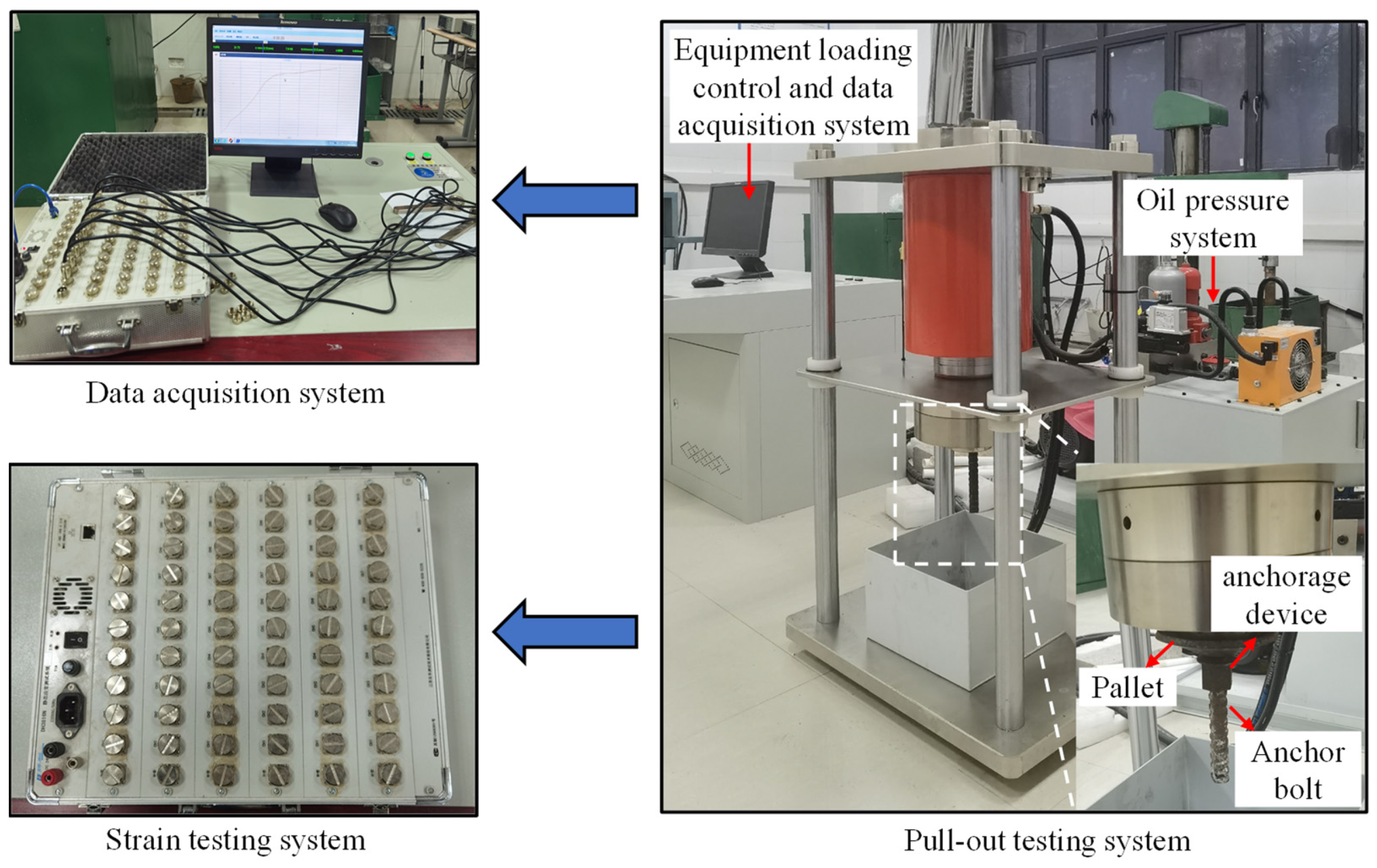
Figure 1. Test equipment.
Energies 15 03313 g001
Figure 2. Mining intrinsic safety borehole camera.
Energies 15 03313 g002
Figure 3. Force-measuring bolt: (a) layout of the bolt’s strain gauges; (b) completed force-measuring bolt.
Energies 15 03313 g003
Figure 4. The dimensions of the steel rod and anchorage specimen: (a) the dimensions of the steel rod; (b) the dimensions of the anchorage specimen.
Energies 15 03313 g004
Figure 5. Prepared coal–rock combined anchoring pull-out test specimens (part).
Energies 15 03313 g005
Figure 6. Relationship between pull-out load and pull-out displacement: (a) the four stages; (b) relationship between pull-out load and pull-out displacement at different pull-out rates.
Energies 15 03313 g006
Figure 7. Relationship between maximum pull-out force and maximum pull-out load time under different drawing rates.
Energies 15 03313 g007
Figure 8. Relationship between maximum drawing force and maximum pull-out load time under different pull-out rates: (a) axial force; (b) interfacial shear stress.
Energies 15 03313 g008
Figure 9. Bolt specimens after pull-out.
Energies 15 03313 g009
Figure 10. Failure characteristics of the coal–rock composite anchor after pull-out: (a) external damage characteristics; (b) damage characteristics of internal borehole.
Energies 15 03313 g010
Figure 11. Time differential development of cracks on the coal–rock combined anchorage body.
Energies 15 03313 g011
Figure 12. Stress diagram of the bolt during the pull-out test.
Energies 15 03313 g012
Figure 13. Mohr–Coulomb strength criterion.
Energies 15 03313 g013
Table 1. Roadway geotechnical properties.
NameLength/mmDiameter/mmRemark
bolt110021.6
epoxy resin glueA and B glue 1∶1
Table 2. Ratio design of surrounding rock on anchor specimen.
Surrounding RockCement MarkWater: Cement: Sand: Stone (Mass Ratio)
coal42.50.8∶0∶0.5∶2.5
rock42.50.49∶1∶1.47∶1.68
Publisher’s Note: MDPI stays neutral with regard to jurisdictional claims in published maps and institutional affiliations.