Article

Thermochemical Modeling of Metal Composition and Its Impact on the Molten Corium–Concrete Interaction: New Insights with Sensitivity Analysis

1
Department of Mechanical Engineering, Khalifa University of Science and Technology, Abu Dhabi P.O. Box 12277, United Arab Emirates
2
Department of MACE, School of Engineering, University of Manchester, Manchester M13 9PL, UK
3
Department of Nuclear Engineering, Khalifa University of Science and Technology, Abu Dhabi P.O. Box 12277, United Arab Emirates
4
Emirates Nuclear Technology Center (ENTC), Khalifa University of Science and Technology, Abu Dhabi P.O. Box 12277, United Arab Emirates
*
Author to whom correspondence should be addressed.
Energies 2022, 15(9), 3387; https://doi.org/10.3390/en15093387
Submission received: 25 March 2022 / Revised: 19 April 2022 / Accepted: 25 April 2022 / Published: 6 May 2022
(This article belongs to the Special Issue Nuclear Engineering and Technology)

Abstract

:
The characterization of molten corium–concrete interaction (MCCI) has increasingly become a cause of concern because, in the case of a severe nuclear accident, the core could meltdown and release radiation into the environment. The objective of this study was to determine the thermochemical impact of metal content in the corium and analyze the effect of corium metal content on ablation depth, corium temperature, its viscosity and surface heat flux, and production of hydrogen, carbon monoxide, and carbon dioxide. The governing heat transfer equations were solved while considering the various thermochemical reactions in the existing numerical code in a comprehensive way. The developed MCCI model in CORQUENCH was validated against the data available in the literature. Our findings showed that the composition of corium, especially its metal content, has a noticeable effect on mitigating or aggravating the ablation depth and nuclear reactor integrity. We observed that during molten corium–concrete interaction, zirconium plays a significant role and its presence can increase the ablation depth exponentially from 18.5 to 139 cm in the investigated case study. It was found that the presence of zirconium in the corium instigated various thermochemical reactions continuously, and thus the injected water, instead of quenching the molten corium, enhances the temperature by facilitating exothermic reactions. Additionally, due to the presence of zirconium, the production of hydrogen and carbon monoxide increases by 45 and 52 times, respectively and the generation of carbon dioxide becomes zero because the zirconium reacts with carbon dioxide continuously, converting it to carbon monoxide.

1. Introduction

Understanding molten corium–concrete interaction is of fundamental importance in the safety assessment of a reactor. During a major nuclear accident, melt/corium may originate in a nuclear reactor. This corium is a combination of fuel, cladding, and reactor structural elements. The interaction of this melt/corium with the concrete is identified as molten corium–concrete interaction. This melt/corium may breach out of the reactor bowl and be exposed to the concrete cemented at the sidewalls and bottommost part of the nuclear reactor. The properties of molten corium are controlled by several parameters such as the type of the coolant and the time it is introduced into the reactor. However, if the reactor cavity is pre-filled with coolant (water) before the occurrence of a severe accident, the molten corium would first encounter water and then the cemented concrete. Moreover, the physical illustrations of the core debris cooling in the presence of overlying water are shown in Figure 1a,b. Amidu et al. [1] investigated the failure of the reactor pressure vessel and suggested mitigating strategies and various assessment methods. They mentioned that in the case of a boiling crisis, the reactor vessel fails near the beltline due to a process known as the focusing effect. Farmer [2] observed that the molten corium divides into fragments/debris of various sizes depending upon coolant properties and different cooling mechanisms. Similarly, this interaction could escalate the amount of heat transfer and would yield a substantial amount of steam. Thus, the conversion of water into steam transfers a significant amount of heat. However, this substantial amount of heat transfer could lead to a steam explosion and compromise the integrity of the reactor structure. Moreover, the molten corium fragments sinking to the bottom of the reactor could lead to the formation of a particle bed. This particle bed is formed due to the entrainment of molten corium through the permeable crust, as shown in Figure 1b. Thus, it is essential to determine the various mechanisms and processes that lead to the formation of the particle bed. This approach helps to estimate the layer particle size, porosity, and permeability [2].
It is important to mention that the various parameters controlling the formation of particle bed are estimated by the deposition and precipitation of disintegrated particles. However, the uncertainty grows with the advancement of these activities. Even when maximum heat is not removed at the initial phase of the accident, the corium cooling mechanism becomes highly ambiguous. Moreover, with the current level of MCCI understanding and experimental limitations, it is not possible to determine the uncertainties of the MCCI [3]. Thus, we do not consider the coolant pre-filled condition with the relative formation of the particle bed in this study. Similarly, after an accident, the molten corium could spread out overwhelmingly to the surroundings of the nuclear reactor [2]. Thus, concrete ablation could occur, even in the early stages of a nuclear accident. These consequences make it necessary to simulate the MCCI for nuclear power plants to determine the control of concrete ablation with the injection of coolant into the reactor cavity. The current findings utilizing the proposed modeling approach would improve the selection of power plants’ design components, such as concrete, cooling systems, and coolant properties, thereby reducing the risk of damage due to MCCI.
Over the last few decades, several studies investigating different aspects of thermal-hydraulics components and various modeling approaches related to nuclear power plants have been conducted [4,5,6,7,8,9,10,11,12,13,14,15,16]. However, the safety of nuclear reactors and various incident plans has not received the required numerical consideration to reduce MCCI and the various factors affecting it [17]. By comparison, several MCCI experiments have been performed by various governments and organizations for different nuclear reactor cavity conditions, such as COTELS, COMET-L3, ECOKATS-2, MACE, MCCI, SWISS, and WETCOR. Refs. [18,19,20,21,22] conducted WETCOR and SWISS experiments at Sandia National Laboratory (SNL). COTELS was performed by Maruyama et al. [23]. Alsmeyer et al. [24], after various experiments, performed the ECOKATS-2 in the EU. At Argonne National Laboratory, [25,26] performed a series of experiments known as MACE. Similarly, [27] performed COMET-L3; VULCANO was performed by [28]; MOCKA was performed by [29]. However, due to the explosion risk of stream and hydrogen, pre-filled nuclear reactor cavity experiments have still not been attempted to date.
A benchmark numerical study was executed by [30], who used physical models on VVER1000 that reported the creation of hot molten corium inside the reactor. Bixler and Nathan [31] simulated the Peach Bottom nuclear power plant and performed an MCCI analysis. Spengler [32] performed the scale-up of MCCI from a small-scale experiment scale to a nuclear reactor scale. To forecast the molten corium cooling behavior and change in its properties, different models and/or simulators have been developed in the past: Bradley et al. [33] developed CORCON-Mod3; MEDICIS and MAAP were modeled by [34]; SOCRAT was developed by [35]; Polidoro et al. [36] modeled CORIMUM-2D, and Farmer [2] developed CORQUENCH. Amidu [1] and Amidu [37] developed various models in OpenFoam and investigated the influence of water ingression and a melt eruption model in Melcor.
In this research, we used the CORQUENCH code to determine and forecast the various processes involved in MCCI. CORQUENCH has the capability to perform multi-nodal analysis and can use various models to simulate MCCI. These models include the corium eruption model, water ingression model, corium-concrete thermal model, and ablation of concrete model. In 2018, Farmer developed them after performing various MCCI-based experiments. One of the notable of these experiments is the Melt Attack and Coolability Experiment (MACE); these are some of the most extensive MCCI experimental programs and are reported by Farmer et al. [38,39]. The goal of MACE is to estimate the corium cooling characteristics under circumstances similar to those in a nuclear reactor. They found that the melt quenching took place by injecting water. However, in performing the M-0 test, they witnessed that a crust originated on the surface of corium with the introduction of water. It was also observed that the formation of solid crust obstructed the contact of injected water with corium. To validate the formation of solid crust and its stability, Farmer [40] increased the size of the experiment to 120 × 120 × 20 cm, known as the M-3b test. After executing the MACE research program, they performed MCCI experiments at ANL, which were completed in 2010. The goal of performing MCCI experiments was to develop an experimental database and to define various corium-related cooling mechanisms. In order to mitigate the damage caused by MCCI during a severe nuclear accident, Khurshid et al. [41] determined the effects of melt/corium temperature, the composition of concrete, and water injection time on MCCI. They found that material with high solidus and liquidus temperature could mitigate the concrete ablation and could act as a shield due to their high thermal resilience characteristics.
It is important to mention that the various MCCI experiments showed that the safety of a nuclear reactor during an accident is immensely affected by an increase in axial depth of concrete ablation. Therefore, to confirm the ability of the model developed in this study, the depth of concrete ablation in axial and radial directions should be compared with the experimental data. From various molten corium–concrete interaction experiments, we selected CCI-2 and SURC-2 to validate the developed model with the experimental data because these molten corium–concrete interaction experiments were executed under BWR and PWR conditions, siliceous and LCS-based concrete, and dry and dry-late flooding. The schematic adopted in this study for analyzing the effect of corium composition on concrete ablation is shown in Figure 2. Primarily, the composition of melt/corium is analyzed in detail, because the composition dictates the corium temperature and sources of heat, including the generation by fission reaction and generation through corium oxidation. Thus, it is important to understand the effect of various metals on corium–concrete interaction. The developed model can be effectively utilized to analyze the molten corium–concrete interaction with the change in corium composition in nuclear power plants. It is important to mention that, to date, the material selection during the reactor design stage is based on mechanical and heat transfer properties, and melting point values. The current study aimed to assess the effects of such materials during a severe accident and thus minimize the severe consequences in the case of an accident in a real nuclear reactor.

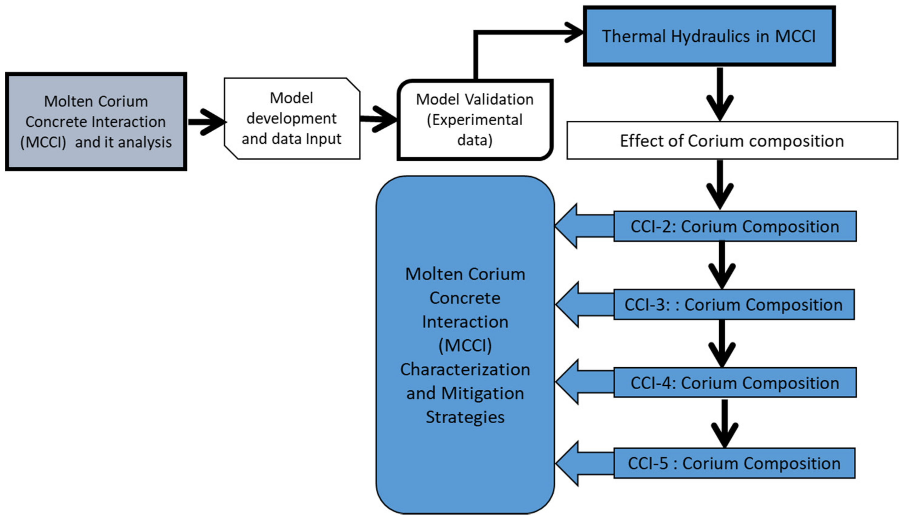
2. Modeling Corium Composition, Viscosity, Heat Transfer, and Ablation

The composition of corium is one of the most important parameters as it defines the corium temperature, sources of heat, including the generation of heat by fission reaction and generation of heat by corium oxidation, and the thermal energy produced in the thermochemical reaction concerning silicon dioxide and metals such as zirconium, iron, and chromium. The various reactions modeled in this study are depicted in Table 1. This table describes stoichiometric factors of different chemical reactions used to model the correlation of the oxidizing agents (CO2, H2O, and SiO2) and the metals present in the corium. To simulate the effect of various gas-related chemical reactions, it is assumed that the metal oxidizes gradually first with zirconium, followed by silicon and chromium, and lastly with iron. The different terms in the energy conservation equation for molten corium include energy terms for source and sinks for the overlying atmosphere and concrete. The energy conservation equation for molten corium is as follows [2]:
e = 1 m { m e + χ m , U O 2 m q d e c A b h t T m T t A b h b T m T b A s h s T m T s + E H 2 O A b m b , H 2 O + A s m s , H 2 O + E C O 2 A b m b , C O 2 + A s m s , C O 2 + E S i O 2 A b m b , S i O 2 + A s m s ,   S i O 2 + 1 χ c n g , g ρ c o n e c o n , d A b η b + A s η s A b ρ e b δ b + ρ e t δ t A s ρ e s δ s X c ρ s o l , m e η s δ b + δ t ρ e s A C H m A b m e n t e + m c o r e e c o r e m }
where m is the mass of melt/corium zone ith constituent, e is the enthalpy of melt/corium (J/kg), χ is the weight fraction, Ab is the basemat surface area in the axial direction, which is presumed to be equal to the melt pool top surface area), ecore is the corium specific enthalpy draining out of the reactor vessel, As is the melt/corium surface area in contact with the radial surface of concrete, Tm is the molten corium temperature, econ,d is the concrete enthalpy at the decomposition temperature, E H 2 O is the metal reaction heat (undergoing oxidation by H2O), E C O 2 is the metal reaction heat (undergoing oxidation by CO2), h is the interfacial heat transfer coefficient, E S i O 2 is the zirconium reaction heat (undergoing oxidation by SiO2), and qdec is the molten corium heat decay level (W/kg fuel).
It is important to mention that during MCCI, the mixture viscosity increases due to the concrete inclusion into the molten corium. The molten corium viscosity during MCCI can be determined by the following numerical models. These models are derived by [42,43]:
μ = μ c 1 V s o l V s o l , m a x 2.5 V s o l , m a x μ d + 0.4 μ c μ d + μ c
μ = μ c 1 + 1 2   V s o l V s o l , m a x 1 V s o l V s o l , m a x 4
where   V s o l , m a x is the solid-phase packing fraction used to determine the viscosity of molten corium, μ. Here μc is the continuous phase viscosity, μd is the dispersed phase viscosity, and they are as follows:
μ c = V l i q , m μ m T + V l i q , o μ o T ,
μ d = V s o l , m μ m T s o l , m + V s o l o , o μ o T s o l , o .
It is important to mention that the high viscosity of the molten corium leads to a decrease in transition velocity. This reduces the convective heat transfer of the molten corium. Moreover, the high viscous molten corium leads to a decrease in the mass of molten corium that could escape through the crack/vents formed in the crust, consequently reducing the cooling efficiency.
When molten corium encounters the cold concrete, after reacting and dissolving a portion of it, a layer of the crust can form on the surface. This solid layer acts as an insulator, reducing the overall heat transfer process. The three different options used to model concrete ablation consist of the following models
a.
Dry-out concrete model;
b.
Dry-out transient concrete model;
c.
Ablation quasi-steady concrete model.
It is imperative to mention that dry-out and dry-out transient concrete models determine the transfer of heat by the process of conduction to the cemented concrete. Moreover, the dry-out concrete model ignores the early transient heating of the concrete surface. However, the dry-out transient concrete model describes all the transient phases. Moreover, the ablation quasi-steady concrete model considers the conventional models for the transfer of heat, ignoring the conduction of heat from the backside of the ablation front. Thus, an accepted approach to estimate the crust growth on the surface of melt/corium and various failure processes is to use the dry-out transient concrete model [2]. After concrete ablation, a new layer of the crust can form on the surface of melt/corium. This crust can either be permeable where the slag is instigated on the top of melt/corium, or it may be impermeable if a film of slag originates at the bottom of the molten corium. In the case of the impermeable crust, the slag film interrupts the heat transfer from the bottom (crust to concrete). Thus, the thermal distribution through the crust is given as:
T x = T s , I T s , f r z T s , I δ s + Q ˙ s , c δ s 2 k s , c x Q ˙ s , c 2 k s , c x 2
where T x = 0 = T s , I and T x = δ s = T s , f r z , Q ˙ s , c is the volumetric decay heat in the crust and is assumed to be uniformly distributed across the crust.
It is essential to mention that the heat transfer coefficients for molten corium to concrete can be estimated by one of the following two approaches: the slag film model or the Kutateladze and Malenkov model proposed by [44,45], respectively. These models estimate the thermal resistance offered by the film of slag formed during MCCI. The coefficient of heat transfer for the axial direction can be derived using these aforementioned models:
h t = 1.5 × 10 3 c m P j k m g 2 / 3 k m L λ , j < j t r 1.5 × 10 3 c m P j k m g 2 / 3 j t r j 2 / 3 k m L λ ,   j j t r
where cm is the specific heat for molten corium, P is the system pressure, km is the thermal conductivity of molten corium, jtr is the transition velocity, and is calculated by 4.3 × 10 4   σ m / μ m and L λ is the Laplace constant, which is calculated by the following equation:
L λ = σ m g ρ m ρ g
where   σ m is the melt/corium surface tension, and ρ m   is   the density of molten corium and ρ g   is   the density of sparging gas.
The second approach to calculate the heat transfer coefficients is to assume that a film of gas instigates with the dissolution of concrete covering the concrete surface. Thus, the heat transfer between melt and the gas film takes place through convection and radiation. In this case, the development of a crust on the surface of the melt/corium is determined by solving the equation of energy balance. The third technique is the Sevón correlation based on CCI experiments, where the coefficients of heat transfer are determined directly from the melt/corium. In this approach, the gas velocity (superficial) is estimated using the data from the literature (experimental data). It was found that the radial coefficients of heat transfer change, subject to the composition of concrete. Nevertheless, the axial coefficient of heat transfer remains unchanged for concrete having siliceous and limestone as basic components. Moreover, the axial heat transfer coefficient is a function of the superficial gas velocity, which is given as:
h t = 2906 v g + 49
The injection of water for quenching the molten corium leads to several cooling mechanisms such as ingression of water, corium bulk cooling, crust breach, and corium eruption. The bulk cooling of molten corium is a phenomenon that occurs before the crust instigation on the melt/corium surface. As soon as the gas is produced, the MCCI escalates and the increase in boiling increases the interface area between corium and water. For extreme conditions [39], estimated the entire sum of heat transfer by injecting coolant and the coefficient of radial heat transfer by:
q w a t = A k e Δ T s a t δ f b + q r
h r = σ s t e f ε m T t , I 2 + T s a t 2 T t , I + T s a t
where δfb is the gas film thickness, consisting of various non-condensable gases and water vapors, which are components of the gas film produced during MCCI, ΔTsat is the surface superheat comparative to the point of water saturation. With the constant flow of water, a stable crust forms, and the molten corium remains insulated under the surface of the crust. Thus, melt/corium can only be quenched if the injected water starts flowing through the cracks formed in the crust. However, with the production of gas, the crust could break apart, allowing the ingression of water, leading to thinning of the boundary (thermal) between the crust and molten corium. In theory, this process can improve the transfer of heat via conduction. The overall heat flux for such cases is estimated by [25]:
q c , d r y k t , c T t , f r z + T s a t δ t + Q t , c δ t 2 ρ v h l v j
To define the crust dry-out limits, the CORQUENCH package allows several model choices. One of these is the Jones model, which is a user-defined crust permeability subroutine to estimate the dry-out heat flux [46]. The Lister/Epstein model is the second model and is the modified version of the model suggested by [25]. It is essential to state that the permeability of crust has an important impact on determining heat transfer with the ingression of water. However, it was mentioned by [47] that the permeability of the crust is empirically calculated; thus, its exact value cannot be determined for a certain case. Therefore, the model given below is used to estimate the dry-out heat flux unless the permeability of the crust is stated [25]:
q c , d r y = C d r y Δ e l v ρ l ρ v g δ t 5 / 13 N k t , c 2 Δ e s a t 2 C t , c Δ e c r a c k 4 / 13 α c , exp [ T t , f r z ( T s a t + σ t , f α t . e x E t , y ) ] 15 / 13
where Cdry is the empirical constant (user-specified), Δesat is the crust specific enthalpy change upon quench from the T t , f r z to T s a t , Δecrack is the crust specific enthalpy change upon cooldown from T t , f r z to T c r a c k , σ t , f is the crust tensile strength, αt,ex is the crust linear expansion coefficient, Et,y is the crust elastic modulus, N is the numerical constant with a value of 0.1 K-m1/2, σ t , f represents crust tensile strength, E t , y is the crust elastic modulus, and subscripts l and v denote coolant liquid and vapor phases, respectively.
In the MACE experiments, the generation of gas was observed moving towards the surface. With the pressure buildup, this gas moved through the cracks, thereby expanding them. When this happens, the melt/corium comes in contact with the coolant (injected water), which leads to the formation of a particle bed. Thus, this phenomenon may lead to the molten corium eruption and an increase in heat transfer. Thus, the eruption of melt/corium occurs once the thermal energy created by the melt/corium is more than the thermal energy removed from the pool of molten corium. Additionally, the scattering of molten corium is determined after its eruption, and this calculation is based on the hypothesis that the entrainment of molten corium is relative to the product of the coefficient of molten corium entrainment and the generated gases’ volumetric flow rate (see [2] for further details).
j m = K e n t j
The proportionality constant ( K e n t ) in Equation (14) can be obtained in three different ways: by a user-defined function; as a relation derived from a model developed by [48]; and from the ANL corium eruption model proposed by [49]. K e n t developed by Ricou–Spalding [48] and Farmer [49] are given as:
K e n t = E ρ g ρ m 1 / 2   ( Ricou Spalding )
K e n t = m ˙ h N h ρ m j   ( ANL   corium   eruption   model )
where N h represent crust hole site density. Farmer [2] mentioned that the M-3b experiment using the Ricou–Spalding model and the ANL molten corium eruption model estimated the same depth of ablation. In this research, we utilized the ANL corium eruption model to determine the entrainment coefficient for corium. In such cases, the corium mass flow rate across the formed cracks and the volume of heat flux by the injection of coolant is estimated by:
m ˙ h = ρ m μ m π D h 2 4 = π ρ m ρ t , c ρ m g D h 4 128 μ m
q e n t = ρ m j m Δ e m , s a t
Next, we used the Lipinski model, proposed by Lipinski in 1980, to calculate the heat flux from the particle bed (dry-out) when it is exposed to the water (coolant), and it is defined as:
q b e d , d r y = 0.756 Δ e l v 1 + ρ m ρ l 1 / 4 2 g ρ v ρ l D b e d α b e d 3 1 α b e d 1 + 6 σ l ( 1 α b e d g D b e d ρ l H b e d α b e d
Spencer et al. [50] performed several experiments known as corium coolant mixing (CCM) at ANL. They considered the particle size to be 0.28 cm and to have 0.4 cm2 bed porosity. Moreover, it was observed by [51] that the rupture of crust occurred with an increase in stresses after coolant injection. Thus, various cooling mechanisms can occur repeatedly when injected water and molten corium interact with each other. For modeling the crust formation on the surface of melt/corium, two approaches can be used to develop the model. The first is to estimate the crust failure by supposing the anchoring of the crust and the formation of cracks in it. In the second, it is assumed that the crust is floating. It was observed by [38,39] that crust anchoring would happen irrespective of the cavity size. In contrast, [45] determined the crust breach using the applied stress on the crust surface and predicted that the melt/corium would be quenched after 180 min. However, this process would decrease the transfer of heat if water is injected from the top and can increase the concrete ablation rate.

3. Results

3.1. MCCI Model Justification/Validation

The modeling of MCCI is a complex process because it depends on several physical and chemical phenomena; for instance: (a) decay heat; (b) melt mass flux after a failed nuclear reactor; (c) thermochemical reactions during MCCI that produce H2O and CO2; (d) chemical reactions among different metals present in the melt/corium, such as zirconium, iron, chromium, and silicon; (e) heat transfer to slag and its movement through the melt/corium; and (f) heat transfer to the surroundings. Therefore, it is essential to justify a numerical model by validating it against experimental data. Thus, we present the justification of the MCCI model developed in CORQUENCH with the experimental data from the literature.

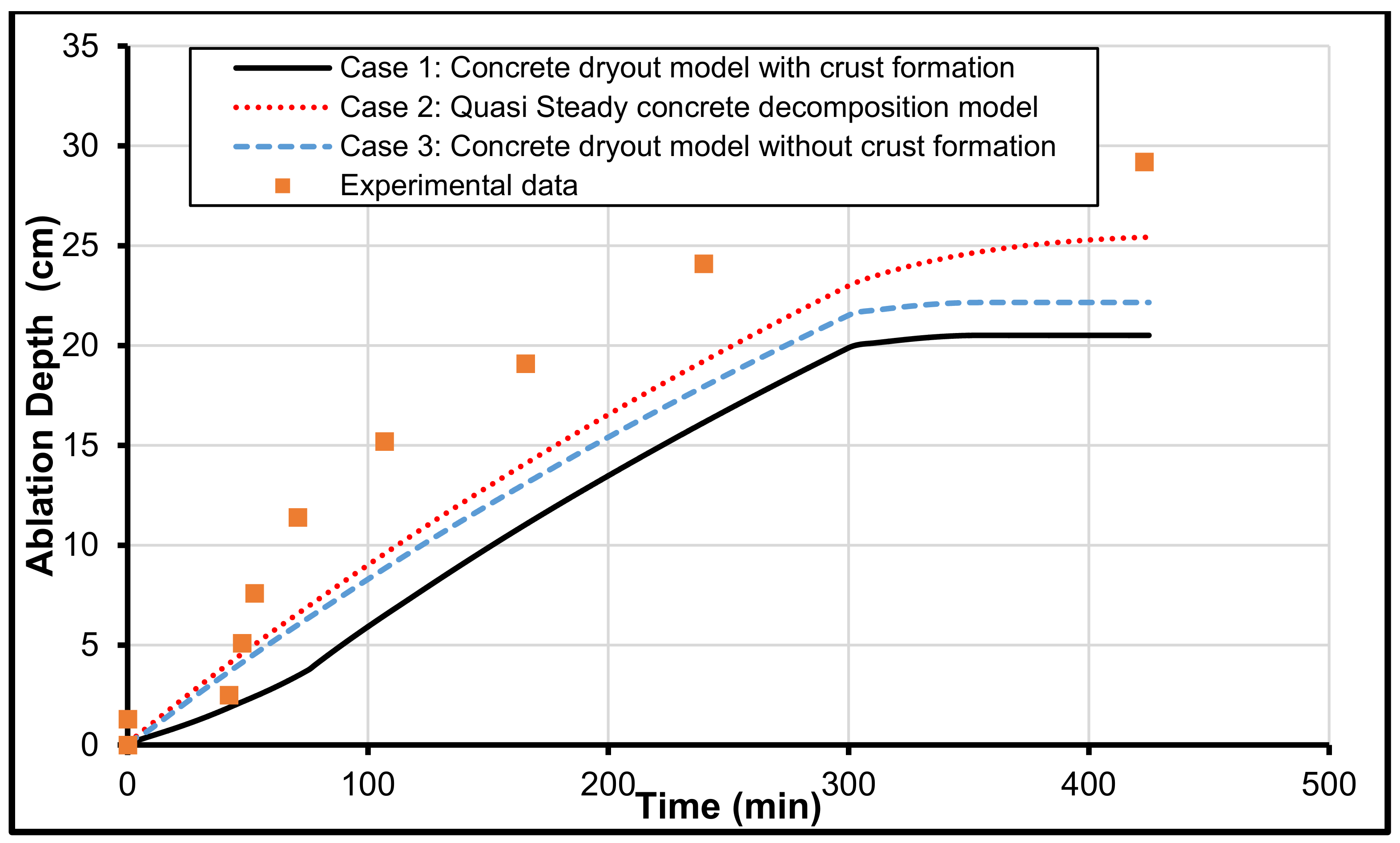
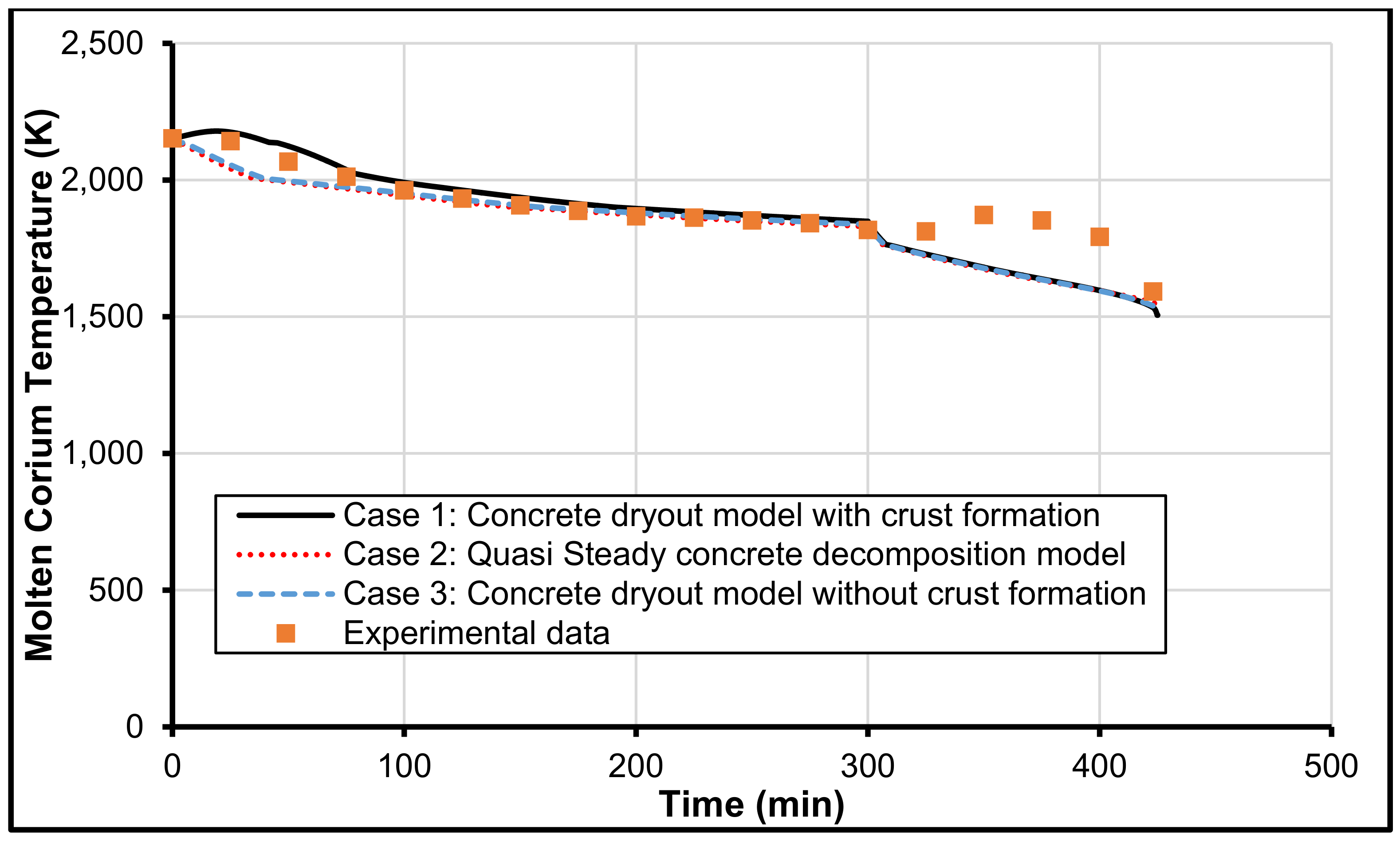
3.2. Validation with MCCI Data (Experimental)

We utilized CCI-2 and SURC-2 from OECD/MCCI and NRC-SNL, respectively, to validate the ability of the MCCI model developed in this research. The different melt/corium and concrete properties for CCI-2 and SURC-2 are provided in Table 2, Table 3, Table 4 and Table 5.

3.3. CCI-2 from OECD/MCCI

The CCI-2 experiment was executed for a 50 × 50 cm geometry with a limestone/common sand concrete (LCS) block having a total melt/corium mass of 400 kg. This experiment was performed for 300 min and then coolant was injected. The flowchart to determine the effects of melt/corium composition on MCCI is shown in Figure 2. Figure 3, Figure 4 and Figure 5 present the comparison of melt/corium temperature and ablation front location, and the prediction of heat flux against the experimental data.
Figure 3 depicts the ablation depth for the CCI-2 experiment in the axial direction. In this study, we used the ablation depth to determine the integrity of the reactor and its containment. It is evident from this figure that sudden concrete ablation takes place once the melt/corium interacts with the concrete. However, the various models shown in the figure show that all the suggested models used in the developed model have a gradual (linear) increase in ablation. The ablation depth increases from zero to 20.5 cm, 22.2 cm, and 25.4 cm, for the dry-out concrete model without crust formation, the dry-out concrete model with crust formation, and quasi-steady concrete decomposition model, respectively. Although all models predict a similar trend, it is apparent from the various predictions that the quasi-steady concrete decomposition model results in a profile adjacent to that of the experimental data.
It is also obvious from the results presented in Figure 3 that the ablation depth becomes constant with the coolant injection, thus indicating that the concrete ablation has stopped. However, the results show that, before the injection of coolant at 300 min, the conduction of heat gradually decreases because the heat energy is disbursed during the process of concrete ablation.
It is important to mention that the heat flux from the top boundary of the melt/corium pool is an important parameter. The experimental measurements during CCI-2 show that this heat flux from the top of the melt/corium pool almost remains at zero before coolant injection (which starts at 300 min), after which there is a spike and then a gradual hyperbolic decline in the heat flux. By comparison, all proposed models as shown in Figure 4 show a constant value of 378 kW/m2 until 424 min. It is speculated that this heat flux prediction causes a discrepancy between experimental data of CCI-2 and the ablation depth predictions shown earlier in Figure 3. Moreover, we believe that, with the injection of coolant, the discrepancy occurs due to the formation of a layer of the solid crust that develops on the surface of melt/corium (at around 305 min). After this transient, the crust thickness increases by constant coolant injection until the melt/corium is finally quenched at 424 min. Thus, with the end of MCCI, the trends in the ablation depth of experimental data and the model predictions become alike because the heat flux is equivalent.
The comparisons of the melt/corium temperature and its various predictions with the developed models against the CCI-2 experimental data are shown in Figure 5. It can be observed that, although all models captured the correct trend in the temperature decay, the dry-out concrete model with the formation of crust shows the finest match with the empirical data. The analysis of experimental data of CCI-2 shows that melt/corium temperature decreases gradually until the time of coolant injection. At 300 min, when coolant is injected, all models show a sharp decrease in temperature from 1818 to about 1600 K. However, the experimental data show an increase in melt temperature from 1818 to 1873 K at 300 and 350 min, respectively. Thus, after that, the temperature immediately drops to 1670 K at 425 min. It is observed from Figure 5 that the heat flux from the melt/corium increases rapidly with the injection of water.

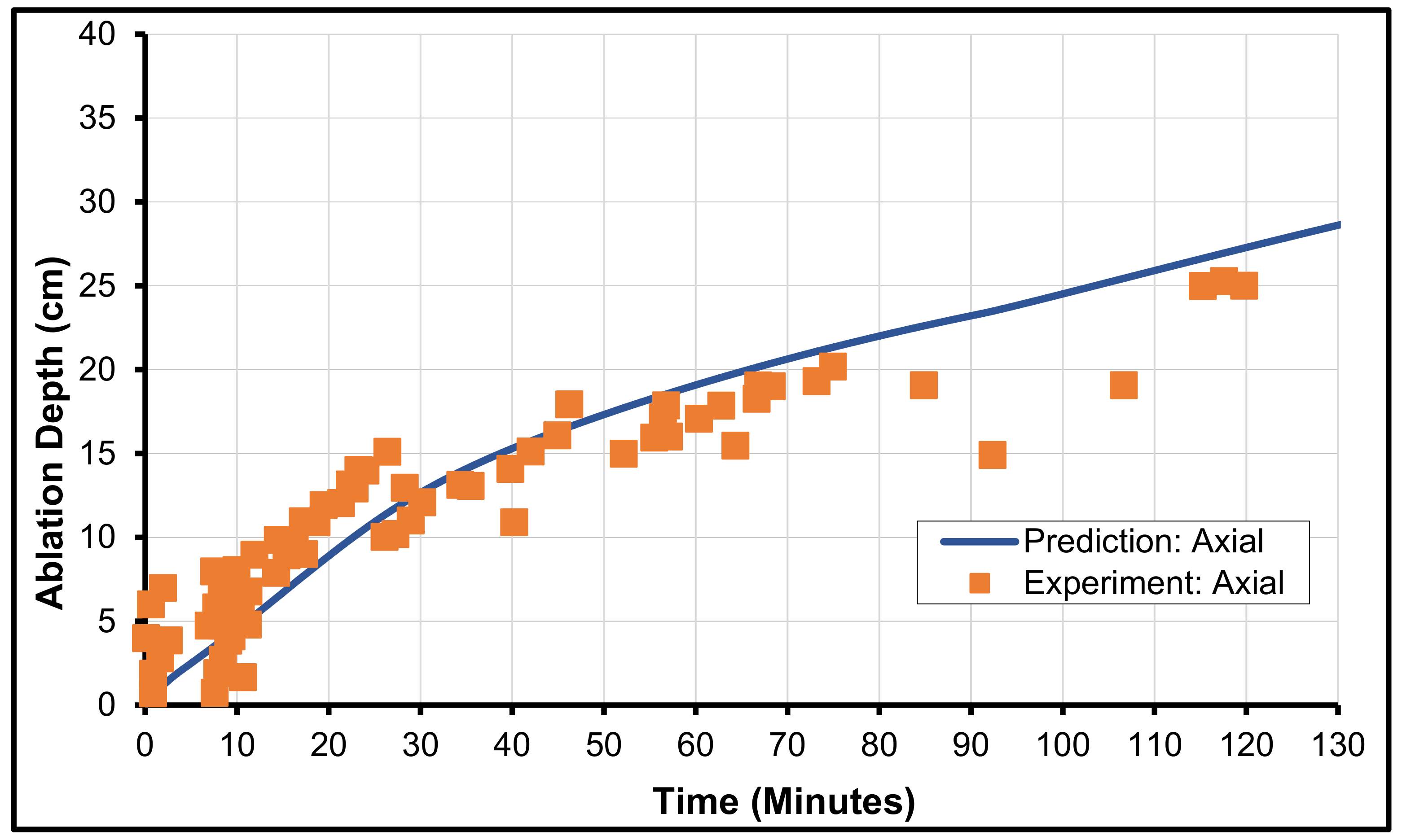
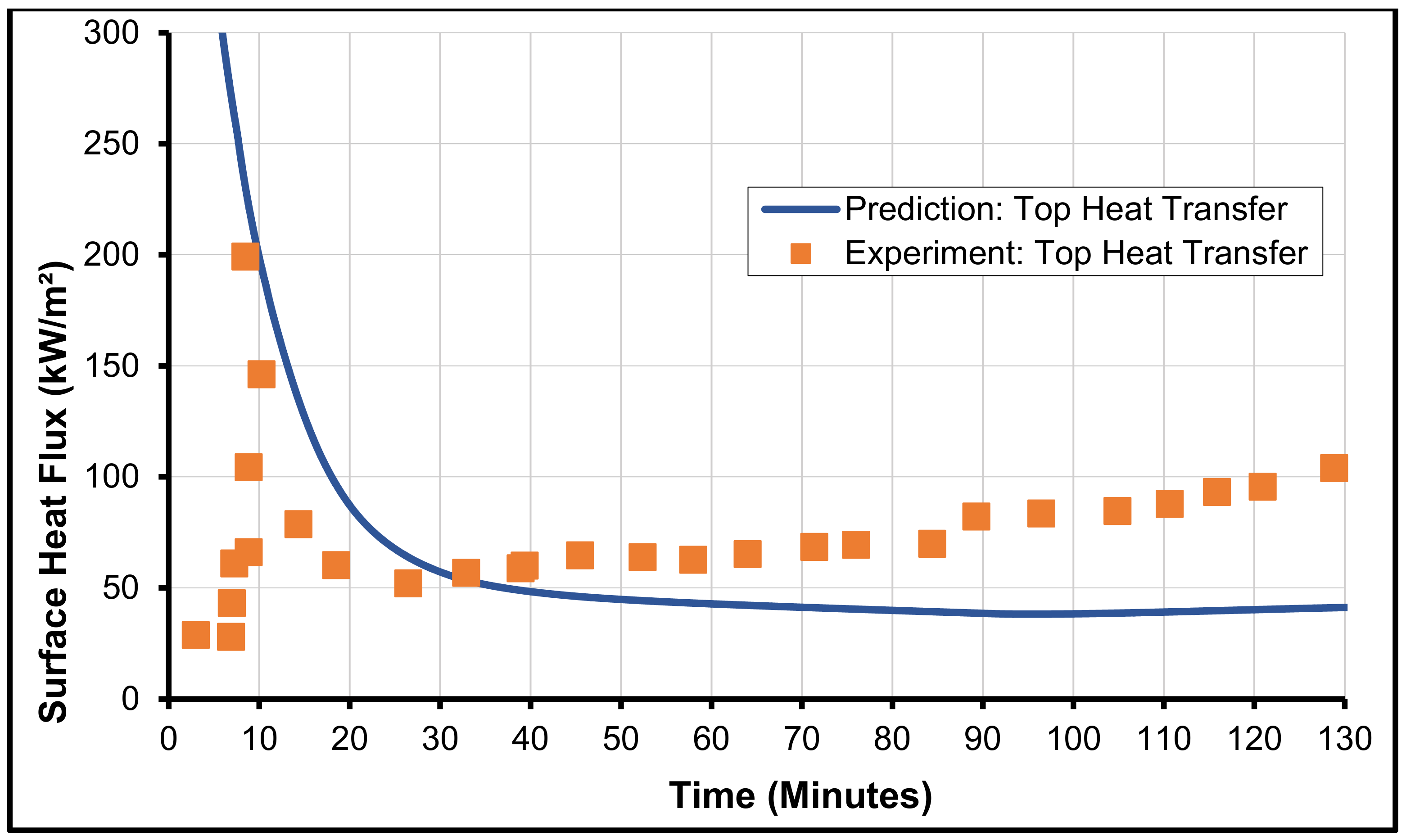
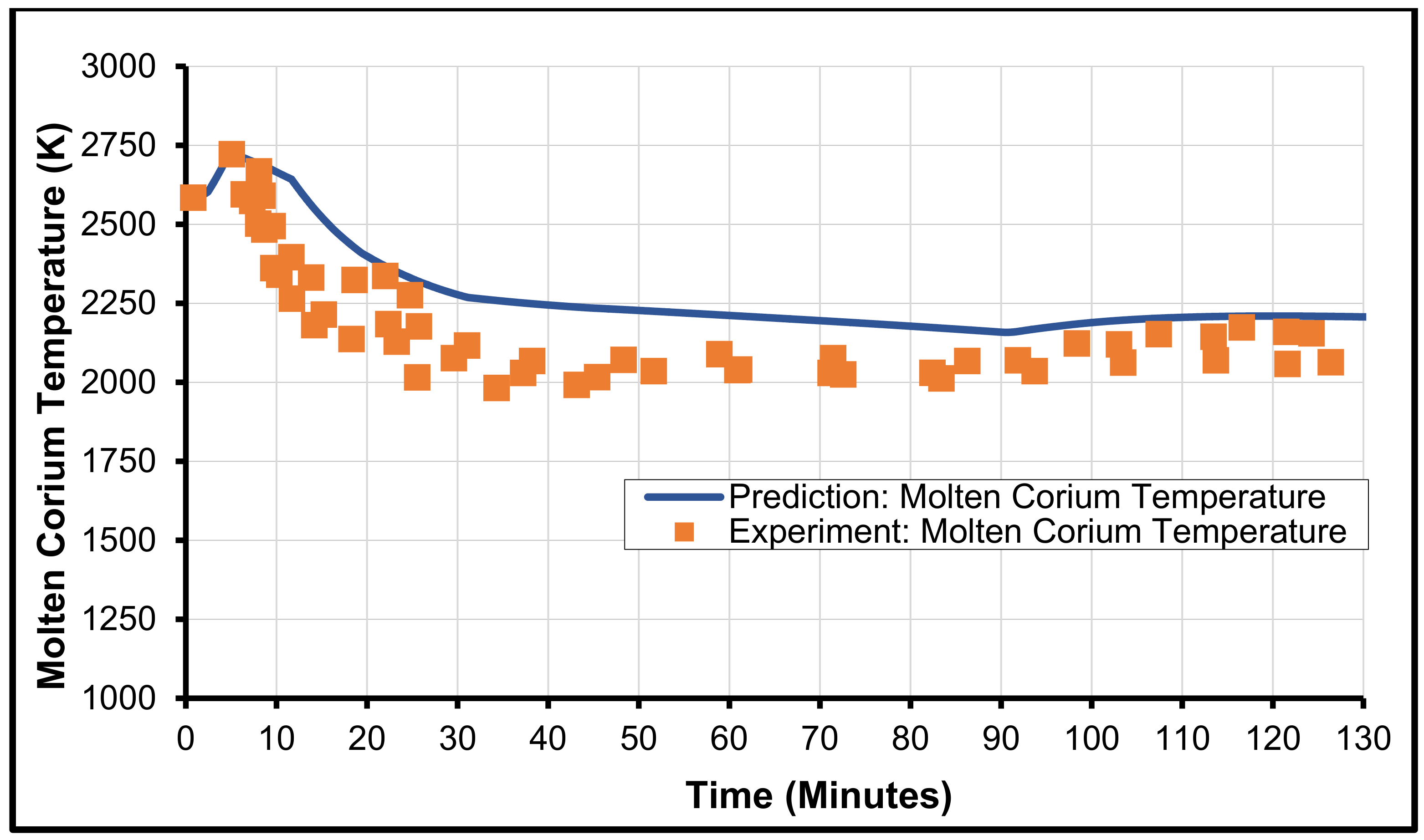
3.4. SURC-2 from SNL

The SURC-2 test was performed in Sandia National Laboratory to evaluate the molten corium–concrete interaction. This test is a 1-D experiment with a cylindrical cavity of 40 cm diameter. We selected this test to validate the model in CORQUENCH because it was executed for a dry cavity under PWR conditions. Thus, this experiment can provide acceptable particulars to model various thermal-hydraulic processes. Moreover, the SURC-2 was executed on the core with oxide material and, thus, it varies from the others. Additionally, it is an experimental setup having a cylindrical layout with inserts of MgO at the sidewalls. They used tungsten susceptors as a heat source to create the melt/corium; these tungsten susceptors were positioned at numerous axial positions inside the experimental arrangement. The composition of corium and its maximum temperature used to perform the SURC-2 are provided in Table 4.
Furthermore, the various properties of concrete and its composition are depicted in Table 5, showing that the concrete used in the SURC-2 is basaltic concrete. The comparisons of the model results and the experimental data are shown in Figure 6, Figure 7 and Figure 8. These figures show the comparison of melt/corium temperature, ablation front location, superficial velocity of produced gas, and heat flux. It is evident from the various predictions that the melt/corium temperature in the initial phase of the experiment is somewhat altered from the experimental data. Nonetheless, the trend is comparable, as shown in Figure 7. It is perceived that the temperature of melt/corium increases with zirconium oxidation, resulting in an increase in the melt solidus temperature. It is imperative to mention that we considered the core and cladding mixture to be fully oxidized.
Eventually, the concentration of the oxidized (UO2-ZrO2) solid-phase diagram reaches the estimated solid concentration with the phase diagram that is oxidized. This includes the different products made by the decomposition of concrete. After reaching this point, the solid concentration reduces because of the slag generation and its movement into melt/corium. Thus, this slag instigation also reduces the overall ablation and its severe effects because zirconium concentration in the melt/corium decreases, which prompts ablation.
It is essential to highlight that predicting MCCI is a complicated process because there are several unknowns and various occurrences that take place throughout the whole process. Therefore, the numerical modeling showed various inconsistencies due to the underlying assumptions of the unknown physical uncertainties. From the results, it is evident that the discrepancies in predicting the temperature of melt/corium occurred in the early phases. Nevertheless, in the later phase, the archived experimental data and their modeling show that the melt temperature, the ablation depth, and its various calculations for SURC-2 were carried out with acceptable accuracy.

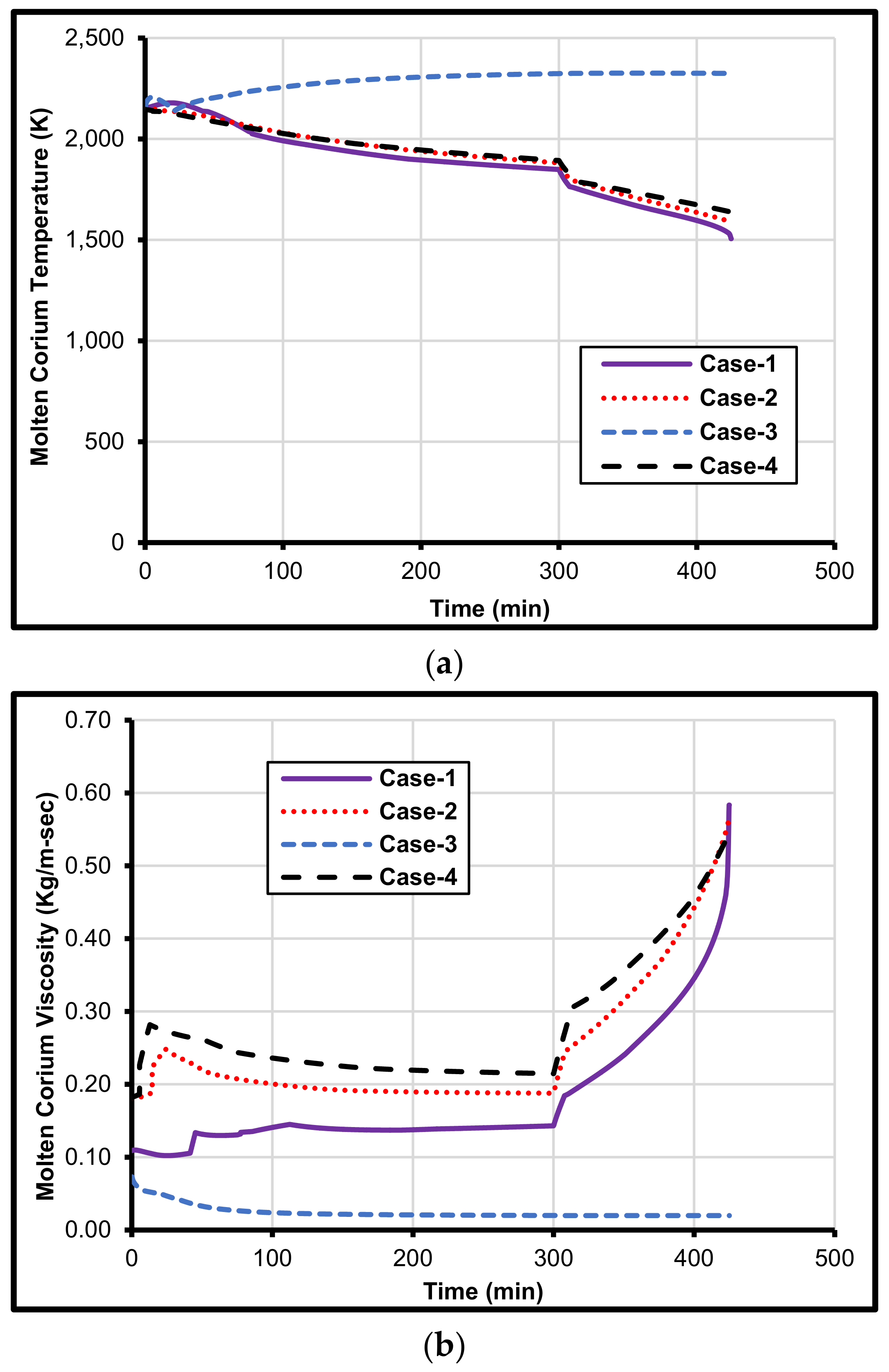
4. Prediction of Metal Composition on MCCI

In this study, an integrated model was developed in CORQUENCH to simulate the interaction of concrete and molten corium. After the validation of the model developed in this study, we performed sensitivity to analyze the effect of melt/corium composition on MCCI, sensitivity analyses were performed by [52,53] but they ignored the effect of metal composition on MCCI. It should be noted here that the composition of melt/corium was taken from the CCI experiments [2]. Four specific composition cases were considered as tabulated in Table 6. It is important to mention that Cases-1, 2, 3, and 4 correspond to CCI-2, CCI-3, CCI-4, and CCI-5, respectively.
Moreover, it is important to mention that one cannot use hypothetical data and must rely on the real/measured composition of molten corium to analyze the effect of the metal content of corium. Moreover, the composition of corium is the most uncertain parameter that hugely affects the corium temperature and sources of heat, including the generation of heat by fission reaction and generation of heat via corium oxidation.
The detailed impact of melt/corium composition on concrete ablation depth, surface heat flux, melt/corium temperature, melt/corium viscosity, and instigation of hydrogen, carbon monoxide, and carbon dioxide are discussed next. Figure 9a depicts the effect of melt composition on the depth of ablation during MCCI. It is important to mention that Case-3 corium is composed of 13.82 kg zirconium and 8.97 kg iron, which are 4.6% and 3.0%, respectively, of the total mass of the melt/corium. It is obvious from the results shown in Figure 9a that the maximum ablation depth that occurred after the injection of coolant at 300 min is 138 cm for Case-3 because of the presence of zirconium and iron since other cases do not have these constituents. In contrast, for Case-1, Case-2, and Case-4, the ablation remains constant at a depth of 18.4 cm only. It is worth mentioning here that all the corium compositions shown in Table 4 contain chromium, but the adverse effect occurred only in Case-3, which contains zirconium and iron. This shows that the use of chromium is safe as compared to zirconium and iron.
Moreover, coolant injection has no quenching effect on melt/corium. These findings show that the metal content of molten corium plays a very important role during MCCI. Thus, it is recommended that all modern reactors should be designed with a comprehensive analysis of metals used in the construction of the reactor and its various parts. Figure 9b describes the effect of melt composition on surface heat flux during MCCI. It can be observed from the results that, after the injection of water at 300 min, Case-1, Case-2, and Case-4 peak at about 1600 kW/m2. However, for Case-3, no change was observed in the profile of the surface heat flux, even after the injection of coolant, which remained constant at 376 kW/m2. This behavior shows that, for Case-1, Case-2, and Case-4, the injected coolant instantaneously decreases the temperature of melt/corium. However, for Case-3, instead of quenching the melt/corium, the injected water enhances its temperature by facilitating exothermic reactions, thereby generating explosive gases such as hydrogen and carbon monoxide, as shown in Table 1 earlier.
The effect of melt/corium composition on molten corium thermal behavior is shown in Figure 10a. It is evident from this figure that, with the increase in time, the temperature of melt/corium decreases for Case-1, Case-2, and Case-4. However, for the Case-3 composition, the temperature of molten corium increases continuously. This steady increase in temperature is speculated to be because of the thermochemical reaction that is continuously taking place due to the presence of zirconium and iron.
It is also apparent from Figure 10a that, after the injection of coolant, the melt temperature for Case-1, Case-2, and Case-4 drop significantly from 1870 to 1500 K, but for Case-3 it increases from 2320 K at 300 min to 2330 K at 350 min. This increase in the temperature of molten corium is also the reason for the increase in ablation depth for Case-3 composition, as was shown in Figure 9a earlier.
Figure 10b displays the effect of melt composition on the viscosity of the molten corium/melt. It is obvious from the results presented in this figure that, over time, the viscosity of Case-1, Case-2, and Case-4 increases as their temperature decreases. However, for Case-3, due to the exothermic chemical reactions, not only does its temperature increase over time but its viscosity also decreases. An increase in local temperature for this composition and a decrease in viscosity leads to increased ablation depth, as was shown in Figure 9a earlier.
Figure 11 shows the production of various gases during molten corium–concrete interaction. It should be noted here that, for comparison purposes, other than the corium composition, all other parameters such as design, initial temperature, etc. were kept constant. It was observed that the presence of metals, such as zirconium and iron in Case-3, had a substantial influence on the production of explosive (H2 and CO) and other (CO2) gases. Figure 11a shows that, for Case-1, Case-2, and Case-4 corium composition, only 1200 moles of hydrogen were produced. However, for Case-3 corium composition, 54,000 moles of hydrogen were formed. This significant increase in hydrogen production is only due to the presence of zirconium and iron.
Similarly, Figure 11b shows that, for Case-3 corium, 142,000 moles of carbon monoxide were produced. However, for Case-1, Case-2, and Case-4, only 2710 moles of carbon monoxide were formed. Figure 11c displays the production of carbon dioxide with various corium compositions. The CO2 is generally considered to be the gas that mitigates the concrete ablation, decreases the temperature of melt/corium, and increases the viscosity of the melt. It can be observed that, for Case-1 corium, 500 moles of CO2 were produced, whereas, for Case-2 and Case-4, 573 moles of carbon dioxide were produced. However, for Case-3, the amount of CO2 generation was almost zero because the produced carbon dioxide is converted into carbon monoxide gas, as shown in Table 1. The analysis shows that the presence of zirconium and iron is critical in the conversion of fire extinguisher gas (CO2) to explosive gas (CO). Therefore, it is important to design the reactor such that the concentration of metals, especially zirconium and iron, is reduced to the minimum.

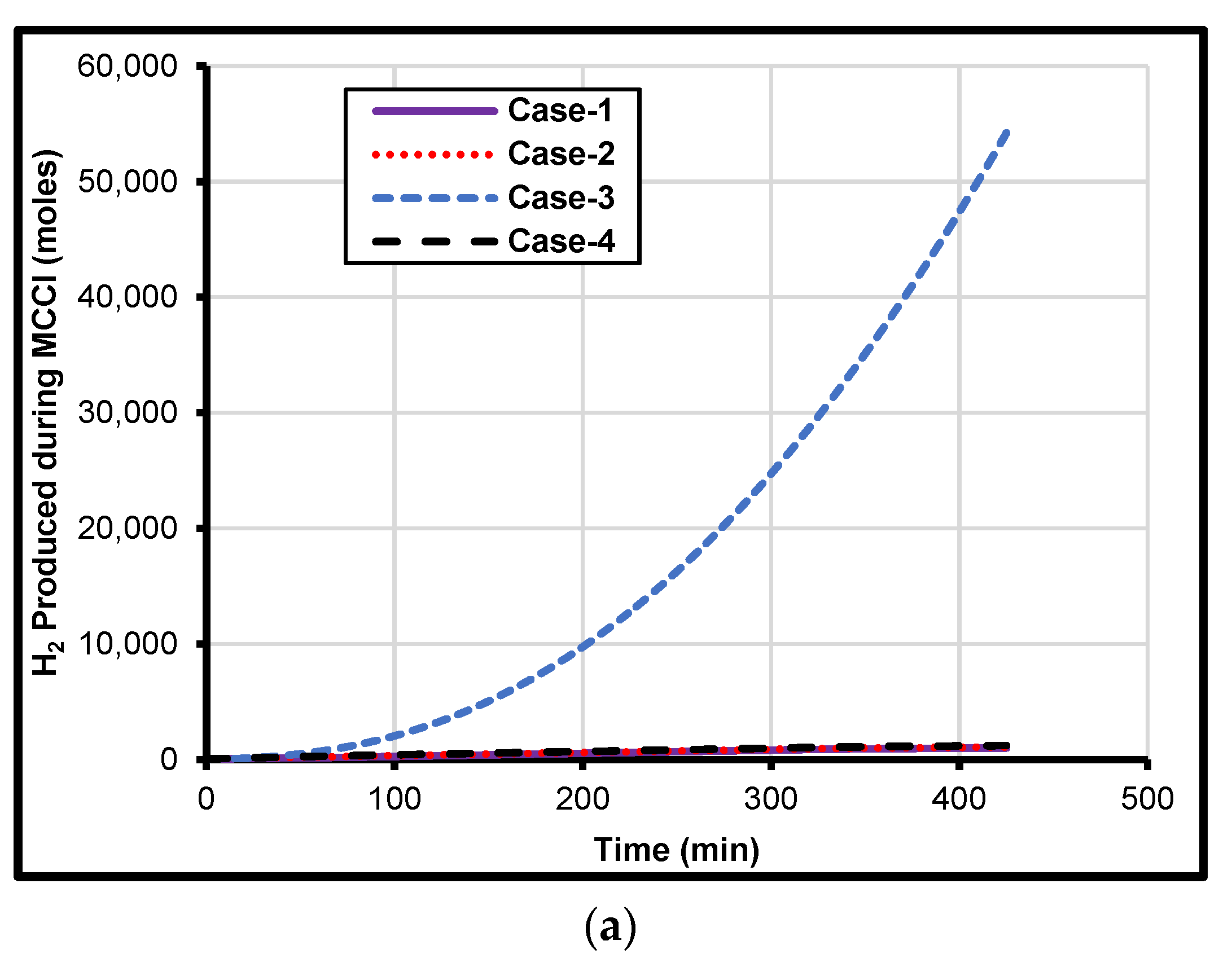
5. Iron and Zirconium Effect on MCCI

The results presented in the previous section showed that the composition of corium would cause a severe nuclear accident if the corium has the composition of Case-3. The analysis showed that Case-3 has two extra metals in comparison to other cases, i.e., zirconium and iron. Therefore, in this section, the effect of the presence of zirconium and iron in the molten corium and its influence on MCCI was obtained through running the developed model in CORQUENCH while considering four different scenarios:
(1) With Fe and Zr;
(2) Without Fe and Zr;
(3) With Fe and without Zr;
(4) Without Fe and With Zr.
The different parameters analyzed that can affect MCCI include ablation depth, surface heat flux, molten corium temperature, and viscosity. The concentration of hydrogen, carbon monoxide and carbon dioxide were also determined for these four scenarios, and the results are depicted in Figure 12, Figure 13 and Figure 14. From these figures, it is evident that the severe effects occurred only in those scenarios of Case-3, which contains zirconium (scenarios 1 and 4). The results presented in Figure 12a show that, for these two scenarios, the ablation depth increased to 138 cm at the water injection time, which is 300 min. However, for the case where both iron and zirconium are absent (scenario 2) and the case where iron is present but zirconium is missing (scenario 3), the ablation depth stays at a depth of 22.6 cm at 300 min. This shows that the use of iron is safe as compared to zirconium.
The effect of melt/corium composition on molten corium thermal behavior for the four different scenarios of zirconium and iron is presented in Figure 13a. It is evident from the figure that, with time, the temperature of melt/corium decreases significantly from 1870 to 1500 K for scenarios 2 and 3. However, for scenarios that contain zirconium (scenarios 1 and 4), the temperature of molten corium increases continuously from 2320 K at 300 min to 2330 K at 350 min. This steady increase in temperature is speculated to be because of the thermochemical reaction that is continuously taking place due to the presence of zirconium. Moreover, the effect of melt composition on the viscosity of the molten corium/melt for the four different combinations of zirconium and iron is depicted in Figure 13b. It is obvious from the results presented in this figure that, over time, the viscosity of scenarios 2 and 3 increases as their temperature decreases. However, due to the exothermic chemical reactions, the melt temperature increases over time, and thus melt viscosity decreases for scenarios 1 and 4.
Figure 12b shows the effect of melt composition on surface heat flux during MCCI. It can be observed from the results that, for the case where both iron and zirconium are absent (scenario 2) and the case where iron is present but zirconium is missing (scenario 3), a peak occurs of about 1600 kW/m2. However, for the scenarios of Case-3 that contain zirconium (scenarios 1 and 4), no change was observed in the profile of the surface heat flux, which remained constant at 376 kW/m2, after the injection of water.
Figure 14 displays the production of various gases for the four different scenarios of zirconium and iron. It is evident from the results presented in this figure that the presence of zirconium had a substantial influence on the production of explosive gases such as H2 and CO, and non-combustible gases such as CO2. Figure 14a shows that scenarios 2 and 3 produce only 1200 moles of hydrogen. However, for scenarios 1 and 4, the amount of hydrogen produced is 54,000 moles. This significant increase in hydrogen production is only due to the presence of zirconium.
Similarly, Figure 14b shows that, for scenarios 1 and 4, the amount of carbon monoxide produced is 142,000 moles. However, for scenarios 2 and 3, only 2710 moles of carbon monoxide were produced. Moreover, the production of carbon dioxide for the four different scenarios of zirconium and iron is presented in Figure 14c. It can be observed that, for scenarios 2 and 3, the total number of moles of carbon dioxide produced is 500. However, for scenarios 1 and 4, the amount of CO2 generation is almost zero due to chemical reactions of produced carbon dioxide with zirconium that convert carbon dioxide into carbon monoxide gas. The analysis shows that the presence of zirconium is critical in the conversion of fire extinguisher gas (CO2) to explosive gas (CO). However, zirconium is used in the cladding, so it is not possible to remove it. Therefore, it is suggested to design the reactor and develop alloys to reduce the use of metals, especially zirconium, to a minimum.

6. Conclusions

Concerning previous attempts to quantify molten corium–concrete interaction, this work emphasizes the importance of thermochemical modeling to characterize the effect of corium composition, especially its metal content. It was found that the proposed approach can be utilized as an effective tool to estimate the molten corium–concrete interaction before and after a nuclear power plant accident. We analyzed the change in ablation depth in response to the effect of melt/corium composition with four different corium constituents and performed a detailed sensitivity analysis of two metals in the worst-case scenario. It was concluded that the corium composition is the foremost controlling factor to mitigate ablation in the case of a nuclear accident. Our findings show that the concentration of zirconium has a significant role during molten corium–concrete interaction. The percentage of zirconium was limited to just 4.6% of the total mass of corium. However, it was found that the presence of zirconium increased the ablation depth from 18.5 to 139 cm. Moreover, the viscosity of corium remains low in the presence of zirconium due to the constant increase in corium temperature because of continuous thermochemical reactions. Additionally, the production of hydrogen and carbon monoxide increases by 45 and 52 times, respectively, and the generation of carbon dioxide becomes zero, because the zirconium constantly reacts with carbon dioxide, converting it to carbon monoxide. Moreover, it was also found that, if zirconium is present in the corium, the water after its injection would not quench the molten corium. However, it would increase the corium temperature by facilitating exothermic reactions. The ablation of concrete during MCCI is a very case-dependent mechanism as it is controlled by the solidus, liquidus, and ablation temperature of concrete.

Author Contributions

Conceptualization, I.K.; methodology, I.K.; software, I.K.; validation, I.K.; formal analysis, I.K. and I.A.; investigation, I.K.; resources, I.A.; data curation, I.K.; writing—original draft preparation, I.K.; writing—review and editing, I.K.; visualization, I.A.; supervision, I.A.; project administration, I.A.; review and editing, I.A.; project administration, Y.A.; funding acquisition, Y.A.; review and editing, Y.A. All authors have read and agreed to the published version of the manuscript.

Funding

This research is supported by Abu Dhabi’s Advanced Technology Research Council via the ASPIRE Award for Research Excellence program (AARE)-2020, Award No. [AARE20-151].

Data Availability Statement

Not applicable.

Acknowledgments

The authors acknowledge Khalifa University of Science and Technology. We appreciate Farmer M.T of the Argonne National Laboratory for his support in developing the models using CORQUNECH.

Conflicts of Interest

The authors declare no conflict of interest.

References

  1. Amidu, M.A.; Olatubosun, S.A.; Ayodeji, A.; Addad, Y. Severe accident in high-power light water reactors: Mitigating strategies, assessment methods, and research opportunities. Prog. Nucl. Energy 2021, 143, 104062. [Google Scholar] [CrossRef]
  2. Farmer, M.T. The CORQUENCH Code for Modeling of Ex-Vessel Corium Coolability under Top FLooding Conditions; The United States; Argonne National Laboratory: Argonne, IL, USA, 2018. [Google Scholar] [CrossRef]
  3. Bonnet, J.-M.; Cranga, M.; Vola, D.; Marchetto, C.; Kissane, M.; Robledo, F.; Farmer, M.T.; Spengler, C.; Basu, S.; Atkhen, K.; et al. State-of-the-Art Report on Molten Corium Concrete Interaction and Ex-Vessel Molten Core Coolability; (NEA--7392). Nuclear Energy Agency of the OECD (NEA): Paris, France, 2017. [Google Scholar]
  4. Wu, Z.; Laurence, D.; Iacovides, H.; Afgan, I. Direct simulation of conjugate heat transfer of jet in channel crossflow. Int. J. Heat Mass Transf. 2017, 110, 193–208. [Google Scholar] [CrossRef] [Green Version]
  5. Abed, N.; Afgan, I. A CFD study of flow quantities and heat transfer by changing a vertical to diameter ratio and horizontal to diameter ratio in inline tube banks using URANS turbulence models. Int. Commun. Heat Mass Transf. 2017, 89, 18–30. [Google Scholar] [CrossRef] [Green Version]
  6. Wu, Z.; Laurence, D.; Afgan, I. Direct numerical simulation of a low momentum round jet in channel crossflow. Nucl. Eng. Des. 2017, 313, 273–284. [Google Scholar] [CrossRef] [Green Version]
  7. Kahil, Y.; Benhamadouche, S.; Berrouk, A.S.; Afgan, I. Simulation of subcritical-Reynolds-number flow around four cylinders in square arrangement configuration using LES. Eur. J. Mech.-B/Fluids 2019, 74, 111–122. [Google Scholar] [CrossRef]
  8. Wu, Z.; Laurence, D.; Utyuzhnikov, S.; Afgan, I. Proper orthogonal decomposition and dynamic mode decomposition of the jet in channel crossflow. Nucl. Eng. Des. 2019, 344, 54–68. [Google Scholar] [CrossRef]
  9. Nguyen, P.T.L.; Uribe, J.C.; Afgan, I.; Laurence, D.R. A Dual-Grid Hybrid RANS/LES Model for Under-Resolved Near-Wall Regions and its Application to Heated and Separating Flows. Flow Turbul. Combust. 2020, 104, 835–859. [Google Scholar] [CrossRef] [Green Version]
  10. Benhamadouche, S.; Afgan, I.; Manceau, R. Numerical Simulations of Flow and Heat Transfer in a Wall-Bounded Pin Matrix. Flow Turbu. Comb. 2020, 104, 19–44. [Google Scholar] [CrossRef] [Green Version]
  11. Ahmed, U.; Apsley, D.; Stallard, T.; Stansby, P.; Afgan, I. Turbulent length scales and budgets of Reynolds stress-transport for open-channel flows; friction Reynolds numbers Reτ = 150, 400 and 1020. J. Hydraul. Res. 2021, 59, 36–50. [Google Scholar] [CrossRef]
  12. Ali, A.E.A.; Afgan, I.; Laurence, D.; Revell, A. A dual-mesh hybrid RANS-LES simulation of the buoyant flow in a differentially heated square cavity with an improved resolution criterion. Comput. Fluids 2021, 224, 104949. [Google Scholar] [CrossRef]
  13. Guleren, K.M.; Afgan, I.; Turan, A. Predictions of turbulent flow for the impeller of a NASA low-speed centrifugal compressor. ASME J. Turbomach. 2010, 132, 021005. [Google Scholar] [CrossRef]
  14. Han, X.; Sagaut, P.; Lucor, D.; Afgan, I. Stochastic response of the laminar flow past a flat plate under uncertain inflow conditions. Int. J. Comput. Fluid Dyn. 2012, 26, 101–117. [Google Scholar] [CrossRef]
  15. Abed, N. Assessment and Evaluation of the Thermal Performance of Various Working Fluids in Parabolic Trough Collectors of Solar Thermal Power Plants under Non-Uniform Heat Flux Distribution Conditions. Energies 2020, 13, 3776. [Google Scholar] [CrossRef]
  16. Abed, N.; Afgan, I.; Cioncolini, A.; Iacovides, H.; Nasser, A.; Mekhail, T. Thermal performance evaluation of various nanofluids with non-uniform heating for parabolic trough collectors. Case Stud. Therm. Eng. 2020, 22, 100769. [Google Scholar] [CrossRef]
  17. D’Auria, F.; Hassan, Y. Challenges and concerns for development of nuclear thermal-hydraulics. Nucl. Eng. Des. 2021, 375, 111074. [Google Scholar] [CrossRef]
  18. Zhdanov, V.; Vasilyev, Y.; Kolodeshnikov, A.; Cherepnin, Y.; Sakaki, I.; Nagasaka, H. COTELS Project (4): Structural Investigation of Solidified Debris in MCCI. In Proceedings of the OECD Workshop on Ex-Vessel Debris Coolability, Karlsruhe, Germany, 15–18 November 1999. Organized in collaboration with Forschungszentrum Karlsruhe (FZK) GmbH. [Google Scholar]
  19. Blose, R.E.; Gronager, J.E.; Suo-Anttila, A.; Brockmann, J.E. SWISS: Sustained Heated Metallic Melt/Concrete Interactions with Overlying Water Pools; Sandia National Laboratories: Albuquerque, NM, USA, 1987. [Google Scholar]
  20. Nagasaka, H.; Sakaki, I.; Kato, M.; Vasilyev, Y.; Kolodeshnikov, A.; Zhdanov, V. COTELS Project (3): Ex-vessel Debris Cooling Tests. In Proceedings of the OECD Workshop on Ex-Vessel Debris Coolability, Karlsruhe, Germany, 15–18 November 1999. Organized in Collaboration with Forschungszentrum Karlsruhe (FZK) GmbH. [Google Scholar]
  21. Blose, R.E.; Powers, D.A.; Copus, E.R.; Brockmann, J.E.; Simpson, R.B.; Lucero, D.A. Core-Concrete Interactions with Overlying Water Pools; The WETCOR-1 Test; Nuclear Regulatory Commission: Washington, DC, USA, 1993. [Google Scholar]
  22. Kato, M.; Nagasaka, H.; Vasilyev, Y.; Kolodeshnikov, A.; Zhdanov, V. COTELS Project (2): Fuel Coolant Interaction Tests under Ex-Vessel Conditions. In Proceedings of the OECD Workshop on Ex-Vessel Debris Coolability, Karlsruhe, Germany, 15–18 November 1999. Organized in Collaboration with Forschungszentrum Karlsruhe (FZK) GmbH. [Google Scholar]
  23. Maruyama, Y.; Tahara, M.; Nagasaka, H.; Kolodeshnikov, A.; Zhdanov, V.; Vassiliev, Y. Kyeongju Recent Results of Mcci Studies in Cotels Project. In Proceedings of the NTHAS3: Third Korea-Japan Symposium on Nuclear Thermal Hydraulics and Safety, Kyeongju, Korea, 13–16 October 2002. [Google Scholar]
  24. Alsmeyer, H.; Cron, T.; Foit, J.J.; Messemer, G.; Schmidt-Stiefel, S.; Haefner, W. Forschungszentrum Karlsruhe GmbH Technik und Umwelt (Germany). In Inst. Fuer Kern- und Energietechnik, Programm Nukleare Sicherheitsforschung; Kriscio, H [Becker Technologies, Eschborn (Germany), Experiment ECOKATS-2: On Melt Spreading and Subsequent Top Flooding; Test and Data Report; Commission of the European Communities: Brussels, Belgium, 2005. [Google Scholar]
  25. Lomperski, S.; Farmer, M.T.; Basu, S. Experimental investigation of corium quenching at elevated pressure. Nucl. Eng. Des. 2006, 236, 2271–2280. [Google Scholar] [CrossRef]
  26. Lomperski, S.; Farmer, M.T. Corium crust strength measurements. Nucl. Eng. Des. 2009, 239, 2551–2561. [Google Scholar] [CrossRef]
  27. Miassoedov, A.; Alsmeyer, H.; Cron, T.; Foit, J. The COMET-L3 experiment on long-term melt–concrete interaction and cooling by surface flooding. Nucl. Eng. Des. 2010, 240, 258–265. [Google Scholar] [CrossRef] [Green Version]
  28. Journeau, C.; Piluso, P.; Correggio, P.; Ferry, L.; Fritz, G.; Haquet, J.; Monerris, J.; Ruggieri, J.; Sanchez-Brusset, M.; Parga, C. Contributions of the VULCANO experimental programme to the Understanding of MCCI phenomena. Nucl. Eng. Technol. 2012, 44, 261–272. [Google Scholar]
  29. Foit, J.J.; Fischer, M.; Journeau, C.; Langrock, G. Experiments on MCCI with oxide and steel. Ann. Nucl. Energy 2014, 74, 100–109. [Google Scholar] [CrossRef]
  30. Gencheva, R.; Stefanova, A.; Groudev, P.; Cranga, M.; Tyrpekl, V.; Duspiva, J.; Kujal, B.; Barc, H.; Chatterjee, B. Investigation of Some Phenomena and Parametrical Studies on VVER1000 MCCI. In Proceedings of the 6th European Review Meeting on Severe Accident Research (ERMSAR-2013), Avignon, France, 2–4 October 2013. [Google Scholar]
  31. Bixler, N.; Gauntt, R.; Jones, J.; Leonard, M. State-of-the-Art-Reactor Consequence Analyses Project: Volume 1, Peach Bottom Integrated Analysis; U.S. Nuclear Regulatory Commission: Washington, DC, USA, 2013. [Google Scholar]
  32. Spengler, C.; Foit, J.; Fargette, A.; Agethen, K.; Cranga, M. Transposition of 2D Molten Corium–Concrete Interactions (MCCI) from experiment to reactor. Ann. Nucl. Energy 2014, 74, 89–99. [Google Scholar] [CrossRef]
  33. Bradley, D.R.; Gardner, D.R.; Brockmann, J.E.; Griffith, R.O. CORCON-MOD3: An Integrated Computer Model for Analysis of Molten Core-Concrete Interactions; User’s Manual; Nuclear Regulatory Commission: Washington, DC, USA, 1993. [Google Scholar]
  34. Cranga, M.; Fabianelli, R.; Jacq, F.; Barrachin, M.; Duval, F. The MEDICIS code, a versatile tool for MCCI modeling. In Proceedings of the ICAPP05, Seoul, Korea, 15–19 May 2005. [Google Scholar]
  35. Bolshov, L.; Strizhov, V. SOCRAT: The System of Codes for Realistic Analysis of Severe Accidents; American Nuclear Society—ANS: La Grange Park, IL, USA, 2006. [Google Scholar]
  36. Polidoro, F.; Parozzi, F.; Manzini, G. Preliminary Assessment of the Thermal Interaction among Corium and In-Vessel Core Catcher in a Large Sodium Fast Reactor. In Proceedings of the 15th International Topical Meeting on Nuclear Reactor Thermal-Hydraulics, NURETH-15 NURETH15-138, Pisa, Italy, 12–17 May 2013. [Google Scholar]
  37. Amidu, M.A.; Addad, Y. The influence of the water ingression and melt eruption model on the MELCOR code prediction of molten corium-concrete interaction in the APR-1400 reactor cavity. Nucl. Eng. Technol. 2022, 54, 1508–1515. [Google Scholar] [CrossRef]
  38. Farmer, M.T.; Spencer, B.W.; Binder, J.L.; Hill, D.J. Status and Future Direction of the Melt Attack and Coolability Experiments (MACE) Program at Argonne National Laboratory; US Department of Energy: Washington, DC, USA, 2001. [Google Scholar]
  39. Farmer, M.T.; Spencer, B.W.; Kilsdonk, D.J.; Aeschlimann, R.W.; Engineering, R. Results of MACE Core Coolability Experiments M0 and M1b; Argonne National Laboratory: Argonne, IL, USA, 2000. [Google Scholar]
  40. Farmer, M.T.; Lomperski, S.; Kilsdonks, D.J.; Aeschlimann, R.W. OEC MCCI-2 Project; Final Report; Argonne National Laboratory: Argonne, IL, USA, 2010. [Google Scholar]
  41. Khurshid, I.; Afgan, I.; Alade, A.M.; Yacine, A. Influence of corium temperature, concrete composition and water injection time on concrete ablation during MCCI: New insights. Prog. Nucl. Energy 2022, 144, 104102. [Google Scholar] [CrossRef]
  42. Kunitz, M. An empirical formula for the relation between viscosity of solution and volume of solute. J. Gen. Physiol. 1926, 9, 715–725. [Google Scholar] [CrossRef] [PubMed] [Green Version]
  43. Ishii, M.; Zuber, N. Drag coefficient and relative velocity in bubbly, droplet, or particulate flows. AIChE J. 1979, 25, 843–855. [Google Scholar] [CrossRef]
  44. Bradley, D.R. Modeling of heat transfer between core debris and concrete. In Proceedings of the ANS Proceedings of the 1988 National Heat Transfer Conference, Houston, TX, USA, 24–28 July 1988. [Google Scholar]
  45. Kutateladze, S.S.; Malenkov, I.G. Boiling and Bubbling Heat Transfer under the Conditions of Free and Forced Convection. In Proceedings of the 6th International Heat Transfer Conference Digital Library, Toronto, ON, Canada, 7–11 August 1978; Volume 1, pp. 281–286. [Google Scholar]
  46. Jones, S.W.; Epstein, M.; Bankoff, S.G.; Pedersen, D.R. Dryout Heat Fluxes in Particulate Beds Heated Through the Base. J. Heat Transf. 1984, 106, 176–183. [Google Scholar] [CrossRef]
  47. Kim, J.; Kwon, S.; Choi, J.; Cho, Y.J. Concrete ablation analysis for molten corium-concrete interaction mitigation strategy. Ann. Nucl. Energy 2019, 132, 615–627. [Google Scholar] [CrossRef]
  48. Ricou, F.P.; Spalding, D.B. Measurements of entrainment by axisymmetrical turbulent jets. J. Fluid Mech. 1961, 11, 21–32. [Google Scholar] [CrossRef]
  49. Farmer, M.T. Phenomenological Modeling of the Melt Eruption Cooling Mechanism During Molten Corium Concrete Interaction (MCCI); American Nuclear Society—ANS: La Grange Park, IL, USA, 2006. [Google Scholar]
  50. Spencer, B.W.; Wang, K.; Blomquist, C.A.; McUmber, L.M.; Schneider, J.P. Fragmentation and Quench Behavior of Corium Melt Streams in Water; Argonne National Laboratory: Argonne, IL, USA, 1994. [Google Scholar]
  51. Magallon, D. Characteristics of corium debris bed generated in large-scale fuel-coolant interaction experiments. Nucl. Eng. Des. 2006, 236, 1998–2009. [Google Scholar] [CrossRef]
  52. Khurshid, I.; Afgan, I.; Alade, A.M.; Yacine, A. A new insight into molten corium concrete interaction with concrete ablation analysis for mitigation scheme. V002T07A028. In Proceedings of the International Conference on Nuclear Engineering, Proceedings, ICONE, Virtual Online, 4–6 August 2021. [Google Scholar]
  53. Khurshid, I.; Alade, A.M.; Yacine, A.; Afgan, I. Thermo-physiochemical analysis of molten corium concrete interaction with concrete: A new insight into ablation analysis. NURETH-35447. In Proceedings of the 19th International Topical Meeting on Nuclear Reactor Thermal Hydraulics (NURETH-19), Virtual Online, 6–11 March 2022. [Google Scholar]
Figure 1. Schematic of molten corium–concrete interaction: (a) view with conduction-limited upper crust at the molten corium–water interface; (b) view with water ingression and molten corium eruption cooling mechanisms [2].
Energies 15 03387 g001
Figure 2. Flowchart to determine the effect of corium composition on MCCI analysis.
Energies 15 03387 g002
Figure 3. Comparison of CCI-2 experimental concrete axial ablation data with the developed model.
Energies 15 03387 g003
Figure 4. Comparison of CCI-2 experimental surface heat flux data with the developed model after injection of water at 300 min.
Energies 15 03387 g004
Figure 5. Comparison of CCI-2 experimental melt/corium data with the developed model.
Energies 15 03387 g005
Figure 6. Comparison of SURC-2 experimental concrete axial ablation data with the developed model.
Energies 15 03387 g006
Figure 7. Comparison of SURC-2 experimental heat flux data with the developed model.
Energies 15 03387 g007
Figure 8. Comparison of SURC-2 experimental melt/corium temperature data (SURC-2) with the developed model.
Energies 15 03387 g008
Figure 9. Effect of melt/corium composition during MCCI at 425 min on (a) ablation depth and (b) surface heat flux.
Energies 15 03387 g009
Figure 10. Effect of melt/corium composition during MCCI at 425 min on (a) temperature of corium and (b) molten corium viscosity.
Energies 15 03387 g010
Figure 11. Effect of melt/corium composition during MCCI at 425 min on the production of (a) hydrogen gas, (b) carbon monoxide, and (c) carbon dioxide gas.
Energies 15 03387 g011aEnergies 15 03387 g011b
Figure 12. Effect of Fe, Zr, and their various combinations during MCCI at 425 min on (a) ablation depth and (b) surface heat flux.
Energies 15 03387 g012aEnergies 15 03387 g012b
Figure 13. Effect of Fe, Zr, and their various combinations during MCCI at 425 min on (a) molten corium temperature and (b) molten corium viscosity.
Energies 15 03387 g013
Figure 14. Effect of Fe, Zr, and their various combinations during MCCI at 425 min on the production of (a) hydrogen gas, (b) carbon monoxide gas, and (c) carbon dioxide gas.
Energies 15 03387 g014
Table 1. Thermochemical reactions applied in CORQUENCH.
Oxidation Based Chemical ReactionsComponent ith γ i S i O 2 γ i H 2 O γ i C O 2
Zr + 2H2O → ZrO2 + 2H2
Zr + 2CO2 → ZrO2 + 2CO
Zr F c o n d ( 1 + F S i ) M Z r 2 M S i O 2 F Z r M Z r 2 M H 2 O F Z r M Z r 2 M C O 2
ZrO2 F c o n d ( 1 + F S i ) M Z r O 2 2 M S i O 2 F Z r M Z r O 2 2 M H 2 O F Z r M Z r O 2 2 M C O 2
Gas Phase:
Si + 2H2O → SiO2 + 2H2
Si + 2CO2 → SiO2 + 2CO
Condensed Phase:
Zr + SiO2 → ZrO2 + Si(l) (T 2784)
Zr + 2SiO2 → ZrO2 + 2SiO(g) (T > 2784)
Si F c o n d F S i M S i 2 M S i O 2 F S i M S i 2 M H 2 O F S i M S i 2 M C O 2
SiO2 F c o n d F S i M S i O 2 2 M H 2 O F Z r M S i O 2 2 M C O 2
2Cr + 3H2O → Cr2O3 + 3H2
2Cr + 3CO2 → Cr2O3 + 3CO
Cr0 2 F C r M C r 3 M H 2 O 2 F C r M C r 3 M C O 2
Cr2O30 F C r M C r 2 O 3 3 M H 2 O F C r M C r 2 O 3 2 M C O 2
Fe + H2O → FeO + H2
Fe + CO2 → FeO + CO
Fe0 F F e M F e O M H 2 O F F e M F e M C O 2
FeO0 F F e M F e O 3 M H 2 O F F e M F e O 2 M C O 2
Table 2. Concrete composition and its properties for CCI-2 [2].
ComponentCCI-2
Concrete composition (Wt %)CO230.42
CaO 26.42
SiO222.01
MgO11.71
H2O4.46
Al2O32.54
Fe2O31.42
K2O0.56
Na2O0.32
TiO20.14
Concrete Properties Solidus temperature (K)1393
Liquidus temperature (K)1568
Ablation temperature (K)1500
Fraction H2O liberated1.00
Fraction CO2 liberated1.00
Table 3. Melt/corium composition and its thermal properties for CCI-2.
ComponentCCI-2
Composition of melt/corium (Kg)U2O242.48
ZrO299.60
Cr25.64
SiO213.56
CaO12.52
MgO4.56
Al2O31.64
Zr0
Fe0
Total400.0
Melt Temperature (K)Initial melt temperature2150
Outer structure temperature750
Table 4. Melt/corium composition and its thermal properties for SURC-2.
ComponentSURC-2
Composition of melt/corium (kg)UO2140.9
ZrO246.1
Zr16.9
Total203.9
Melt Temperature (K)Initial melt temperature2600
Outer structure temperature900
Table 5. Concrete composition and its properties for SURC-2.
ComponentSURC-2
Composition of Concrete (Wt %)SiO257.90
CaO13.80
Al2O37.20
H2O5.00
Fe2O34.40
MgO4.00
K2O3.80
CO21.50
Na2O1.40
TiO20.80
Properties of Concrete Solidus temperature (K)1350
Liquidus temperature (K)1650
Ablation temperature (K)1500
Fraction H2O liberated0.68
Fraction CO2 liberated1.00
Table 6. Composition of different corium used for thermochemical analysis.
S.NoConstituentCase-1Case-2Case-3Case-4
Mass (kg)PercentageMass (kg)PercentageMass (kg)PercentageMass (kg)Percentage
1UO2242.560.6211.456.3169.456.5332.356.3
2ZrO299.624.986.823.164.521.5136.523.1
3SiO213.63.441.911.212.24.165.911.2
4Al2O31.60.42.40.61.50.53.80.6
5MgO4.61.10.50.14.11.40.70.1
6CaO12.53.18.32.211.23.713.02.2
7Cr25.66.424.16.414.14.737.86.4
8Zr0.00.00.00.013.84.60.00.0
9Fe0.00.00.00.09.03.00.00.0
Total400.0100.0375.4100.0300100.0590.01.0
Publisher’s Note: MDPI stays neutral with regard to jurisdictional claims in published maps and institutional affiliations.

