Article

Lean Burn Flame Kernel Characterization for Different Spark Plug Designs and Orientations in an Optical GDI Engine

1
CNR STEMS_Science and Technology Institute for Sustainable Energy and Mobility, Via Guglielmo Marconi 4, 80125 Napoli, Italy
2
Energy Department, Politecnico di Torino, 10129 Torino, Italy
*
Author to whom correspondence should be addressed.
Energies 2022, 15(9), 3393; https://doi.org/10.3390/en15093393
Submission received: 3 April 2022 / Revised: 29 April 2022 / Accepted: 4 May 2022 / Published: 6 May 2022

Abstract

:
Lean burn spark ignition (SI) engines represent an effective solution for improving fuel economy and reducing exhaust emissions and can be implemented both in conventional and hybrid powertrains. On the other hand, lean operation increases cyclic variability with negative impact on power output, engine efficiency, roughness, and operating stability. Although this phenomenon has been widely investigated, the effects of flow field on the inception and development of flames in direct injection spark ignition (DISI) engines under lean burn conditions is not yet completely understood. In particular, the effect of spark plug geometry and electrode orientation with respect to tumble motion has been minimally investigated. For these reasons, two different spark-plug geometries (i.e., single- and double-ground electrode) and three different orientations (i.e., cross-, counter-, and uni-flow with respect to the direction of tumble motion) were investigated in an optically accessible DISI engine for understanding their influence on the initial phase of combustion. The relative air–fuel ratio (AFRrel) was changed from stoichiometric to lean burn (1.00 to 1.30) for different spark timings around the maximum brake torque setting at fixed engine speed (2000 rpm). An image processing procedure was developed for evaluating the morphological parameters of flame kernels and studying the effects of spark plug design on engine operating stability. With a focus on the correlation between the position where ignition occurs with the subsequent locations of the flame kernel during the first phases of the combustion process, the analysis allowed the gathering of a better understanding of the influence that the electrodes’ geometries and orientation can have on the first stages of combustion development.

1. Introduction

Transition to renewable energy sources is significantly changing the automotive sector, and, while fully electric powertrains are expected to dominate the passenger car sector from 2035 afterwards, at least in the European Union, the internal combustion engine will still constitute the backbone of transportation at least for the next decade. Climate change is commonly agreed to be one of the most important challenges mankind has to face [1], and the reduction of greenhouse gas emissions due to human activities is therefore crucial [2]. Different legislative approaches to slow down global warming are being implemented worldwide (e.g., from gradual detachment from fossil fuel to completely banning the sale of new gasoline and diesel vehicles by 2035 [3]) with various impacts of such measures aimed at reducing greenhouse gas emissions [4].
Nevertheless, several studies [5,6,7] forecast that internal combustion engines (ICEs) will continue to play an important role among vehicular propulsion systems for the next decade (also foreseeing their application in hybrid powertrains or thanks to the use of synthetic fuels) and for distributed energy generation solutions. In this context, gasoline direct injection (DI) in spark ignition (SI) engines has been widely adopted in recent years, often in combination with engine downsizing and turbocharging, due to its capability to significantly reduce knock tendency [8,9,10]. The possibility of implementing lean burn combustion systems and reducing fuel consumption is a further advantage of DISI engines [11,12,13], even if this operating regime requires specific aftertreatment systems [14] and features lower combustion stability [15]. Cyclic variability is a well-known, yet not fully understood effect, and is still being investigated [16]. The complexity is due to combination of phenomena that take place simultaneously inside the combustion chamber [17]. The use of lean mixtures leads to slower flame front propagation and emphasizes the effects of flow field motion on the combustion process, thus resulting in excessive irregularity of engine output, with increased cycle-to-cycle variability (CCV) and reduced thermal efficiency [18,19,20].
In [21], the authors combined thermodynamic and optical analysis to study the combustion process in a DI SI optically accessible engine, obtaining satisfactory results by comparing the calculated volume of the burned fraction and the optically measured flame area. Martinez et al. and Irimescu et al. in [22,23] investigated the effects of air–fuel ratio and injection phasing on flame front propagation in an optically accessible DI SI engine, demonstrating how the first predominantly affects the flame shape while the second affects displacement with respect to the spark plug centre. By using the same methodologies, Schirru et al. in [24] investigated the impact of spark plug orientation on flame kernel location and the subsequent flame development process, noting the tendency of the first to form toward the exhaust side. Nevertheless, the low turbulence level (engine speed of 1000 rpm) did not allow the observing of appreciable difference in terms of the location or elongation of the flame kernel. Moreover, Geiger et al. and Lee et al. in [25,26] demonstrated how the implementation of different spark plug designs can extend the lean limit range where the engine operates under stable conditions. Zhao et al. in [16] have studied CCV in a spark-ignited engine using large-eddy simulation and correlated the flame topologies to the peak pressure reached in the combustion chamber, finding how the flame volume shape affects cylinder pressure development.
The present work aims to contribute to gather a better understanding of how the flame–fluid motion interaction affects kernel inception and cycle-to-cycle variability, with a focus on the correlation between the location where ignition occurs (flame kernel) and the successive positions of the flame, up to the location corresponding to the end of the first kernel development, which is generally assumed to be coincident with the crank angle at which 5% of the fuel mass is burnt (CA5). Therefore, thanks to optical techniques, two different spark plug designs and three different electrodes’ orientations with respect to the direction of tumble motion were investigated in an optically accessible DISI engine operating under stoichiometric and lean burn conditions for different spark timings. The displacement of the flame kernel with respect to the inception location was accurately evaluated by applying ad hoc image processing, and correlations between flame kernel displacement and its inception location for different combination of ignition hardware and operating conditions were highlighted.

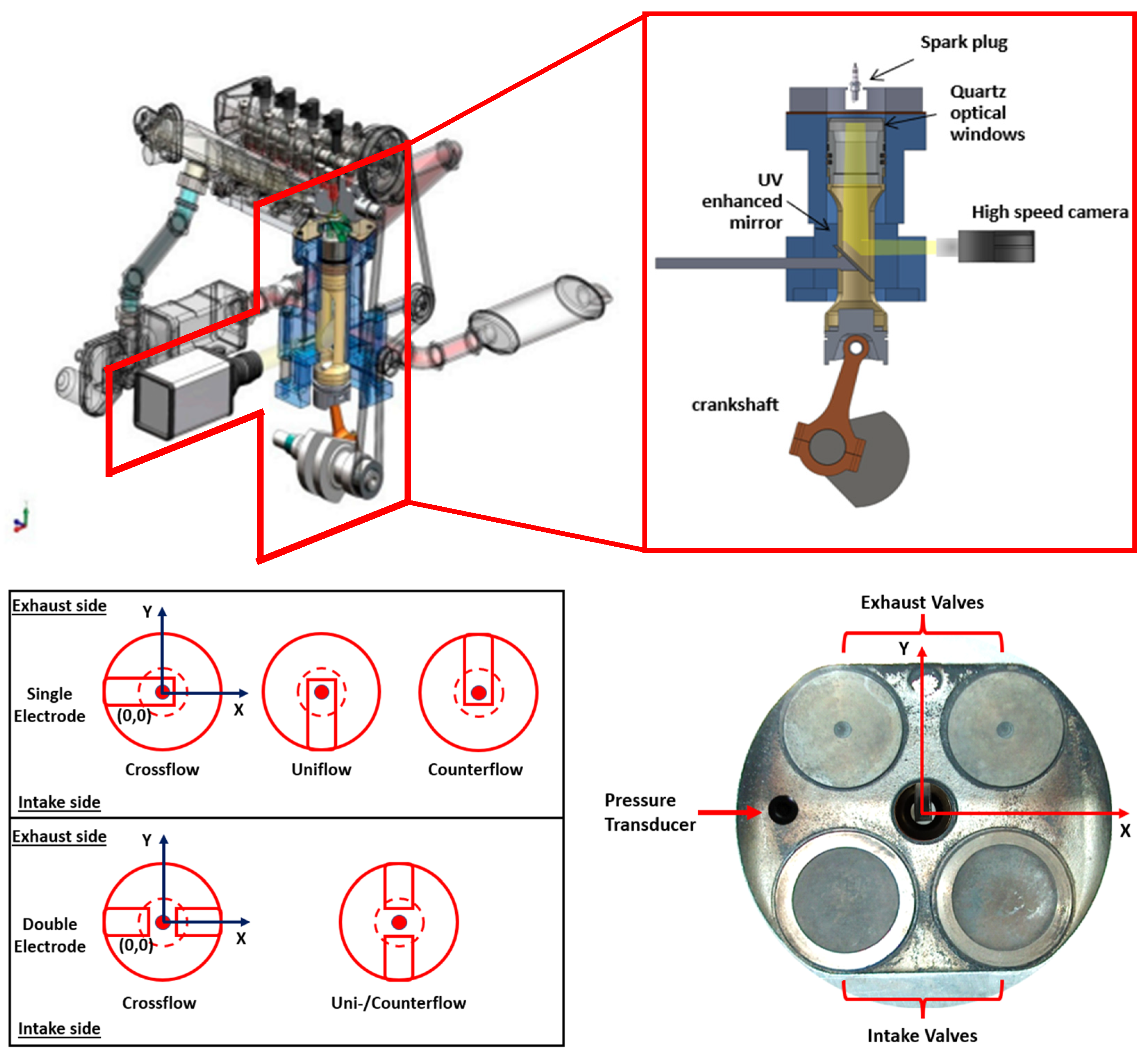
2. Experimental Setup and Methodology

Measurements were carried out on an optically accessible direct-injection spark-ignition (DISI) single-cylinder four-stroke engine. A mass-produced automotive engine, 1.4 L displacement, 4-cylinder in-line, was suitably modified for the optical investigations. The engine was equipped with a four-valve pent-roof head, while the crankcase was modified and designed for a single cylinder that features a Bowditch extended piston design. Table 1 shows the engine specifications and the valves timing (CAD for crank angle degree, B and A for before and after the top dead centre (TDC), respectively; reference is made to the firing TDC).
Figure 1 shows an overview of the experimental setup. Two different spark plugs were tested, with single J-type electrode (Bosch YR7LEU) and a double J-type electrode design (NGK DCPR8EKC), respectively. The cross-flow orientation presents the electrodes perpendicular to the tumble motion, which is predominantly developed along the x axis in Figure 1, while the uni-/counter-flow orientations feature the electrodes parallel to the tumble motion.
The in-cylinder pressure traces were obtained as ensemble-averages of 200 consecutive cycles recorded with a piezo-electric transducer (AVL GH12D) with an accuracy of ±1% and a crank angle resolution of 0.2 CAD. The intake air temperature was controlled at about 300 K and monitored with a thermocouple placed in the intake manifold.
A piezo-resistive sensor was used for measuring the absolute intake pressure with an accuracy of ±1%. Oil and water temperatures were regulated by a thermal conditioning system including an electric heater and a heat exchanger. It was permitted to maintain the water coolant temperature in the range between 330–335 K. The synchronization of various control triggers for ignition, injection, and camera recording was achieved by using an optical encoder mounted on the crankshaft to generate an external clock signal connected to an AVL engine timing unit.
The direct-injection system featured wall-guided (WG) configuration and injection pressure was maintained at 100 bar. The engine speed was fixed at 2000 rpm, and all cases were examined in wide open throttle (WOT) conditions; relative air–fuel ratio (AFRrel) or lambda (λ) was monitored with a UEGO (universal exhaust gas oxygen) sensor that featured an accuracy of ±1%. Table 2 lists engine operating conditions that were investigated (with SA standing for spark advance).

3. Heat Release Rate Analysis

Considering the difficulties to characterize the heat and mass losses of the in-cylinder charge in an optical engine, mainly related to the high blow-by flow, the simplified approach described in [27] for the calculation of the net heat release rate (HRR) was adopted. To calculate the main engine performance and combustion parameters, e.g., the indicated mean effective pressure (IMEP), its coefficient of variation (COV), and the net heat release rate (HRR), a dedicated script was built using the National Instrument (NI) LabView 2020 software. IMEP and HRR were calculated for an ensemble average of 200 consecutive engine cycles for each of the investigated engine operating conditions. The mass fraction burned (MFB) was then calculated on the basis of the integral of the net heat release rate, obtained by means of Equation (1), as follows:
d Q n = γ γ 1 p d V + 1 γ 1 V d P
where dQn is the net heat rate release measured in Joules per crank angle, p is the in-cylinder pressure in Pa, V is the instantaneous cylinder volume in m3, and γ is the ratio of the specific heat of the in-cylinder charge, which was set to 1.35. MFB was then calculated as:
MFB = Q k Q S T Q E V O Q S T  
where the subscript “k” is related to the current crank angle position, while the subscript “ST” refers to the crank angle at spark timing and “EVO” to the crank angle at the exhaust valve opening. Once MFB was calculated, it was possible to identify the CA corresponding to 5% MFB (CA5) and 50% MFB (CA50), taken as representative of the end of the first kernel development angle and of the centre of weight of the flame propagation phase, respectively.

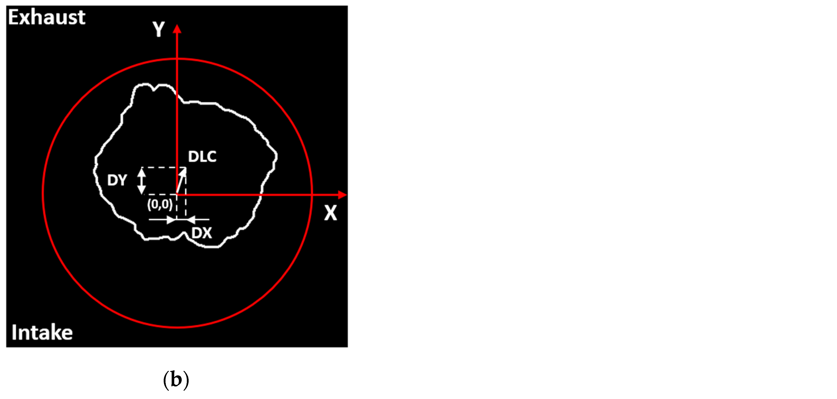
4. Optical Setup and Methodology
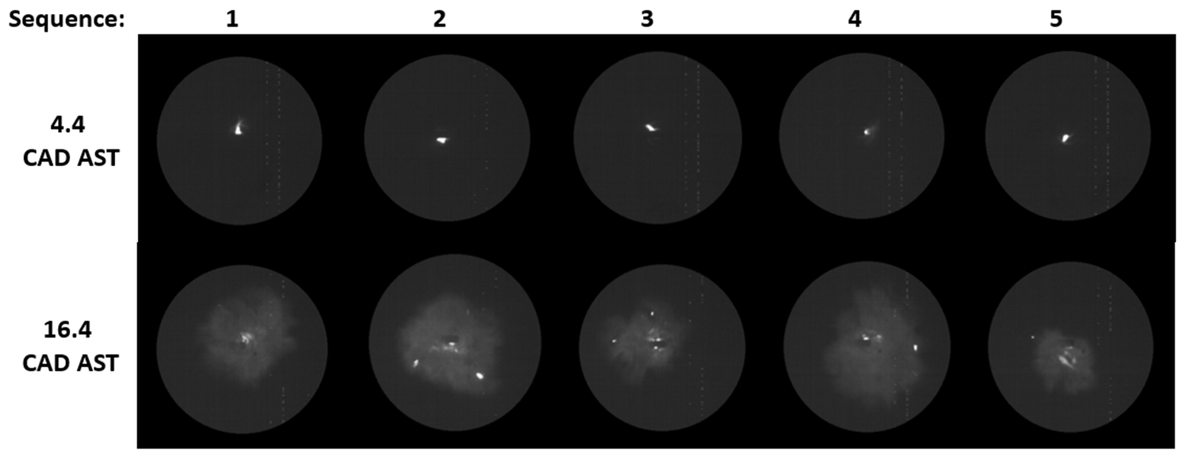
Digital imaging was performed by using a high-speed CMOS camera (CamRecord 5000, 8-bit, 16 μm × 16 μm pixel size by Optronis, Kehl, Germany) equipped with a 50 mm Nikon objective. The camera was set in full chip configuration with a resolution of 512 × 512 pixels and an acquisition speed of 5000 frames per second (equivalent to a dwell time of 2.4 CAD at 2000 rpm), with an exposure time of 167 μs. The f-stop of the objective was set at 2.8 to improve the signal-to-noise ratio without extensive saturation effects. The optical setup allowed 0.19 mm/pixel spatial resolution. Ad-hoc image processing built in NI Vision software environment was used for evaluating flame kernel displacement and its morphology, based on the recorded optical data. As a starting point of the procedure, a circular mask was applied to the images, to limit the investigated area to the quartz window fitted on the piston top and to cut light from reflections at the boundaries of the optical access. Then the level of contrast, gamma (which defines the relationship between a pixel’s numerical value and its actual luminance), and brightness were fixed to improve the quality of the images and reach a suitable level of luminosity of the “foreground” for successive binarization. This was obtained by applying a threshold level that featured a 20% linear decrease from its initial value (25) when AFRrel was swept from stoichiometric to lean burn conditions. Each binary image was treated with the same fast Fourier transform (FFT) to correct drifts and remove small objects out of the foreground. A morphological function permitted to evaluate the area and the coordinates X-Y of the luminous centroid (LC) with respect to the origin of the reference system fixed on the spark plug axis. Finally, the LC’s displacements along the Y-axis (DY) were calculated. DY corresponded to the distance from the plug in the tumble direction; thus, it was considered positive if the flame was elongated towards the exhaust valves. The steps applied for image processing are illustrated in Figure 2.
In order to have a more comprehensive understanding of the origins of CCV, a specific investigation was performed, evaluating the correlation between the kernels and successive flame locations during the process. More specifically, two frames were extracted from each sequence of images; the first relative to the kernel inception (in the range 2.4–4.8 CAD AST) when the spark arc was still observable, and the second close to the CA5 (±0.3%) mark. Figure 3 shows images from five consecutive cycles, relative to the two selected CADs after spark timing (4.4 and 16.4 CAD AST) for the operating condition with an AFRrel of 1.15, spark advance fixed at 12 CAD, cross-flow orientation, and single-plug design. From a preliminary qualitative evaluation, it appears that the flame front propagates in the same region where the kernel first develops. In order to obtain a quantitative analysis of the effect, the Y-displacements of the kernel and of the CA5 flame were compared for all of the examined cases; after linear fitting, three regions were defined based on a calculated coefficient of determination (R2). For a coefficient of determination between 1.0 and 0.7, the case was considered a high-correlation region, from 0.7 to 0.5 a medium correlation, and finally, below 0.5, the correlation was considered to be absent. As an example, Figure 4 reports the correlation related to the condition of Figure 3 by considering 20 consecutive combustion sequences.

5. Results

A combined discussion of the results coming from the thermodynamic and optical analysis is performed in this section; moreover, the information gathered in this work have been further divided into three sub-sections. In the first and second sub-sections, the findings obtained for the crossflow orientation (for the single- and for the double-electrode spark plug designs), first for a fixed SA and for different AFRrel and then vice versa, are discussed. Finally, in the third and last sub-section, the remaining investigated cases are discussed (i.e., uni- and counter-flow configurations for single-electrode and uni- for double-electrode). For the sake of brevity and improved flow of discussion, thermodynamic parameters are mentioned in correlation with the observed flame-related phenomena, and the text is focused on the optical data.

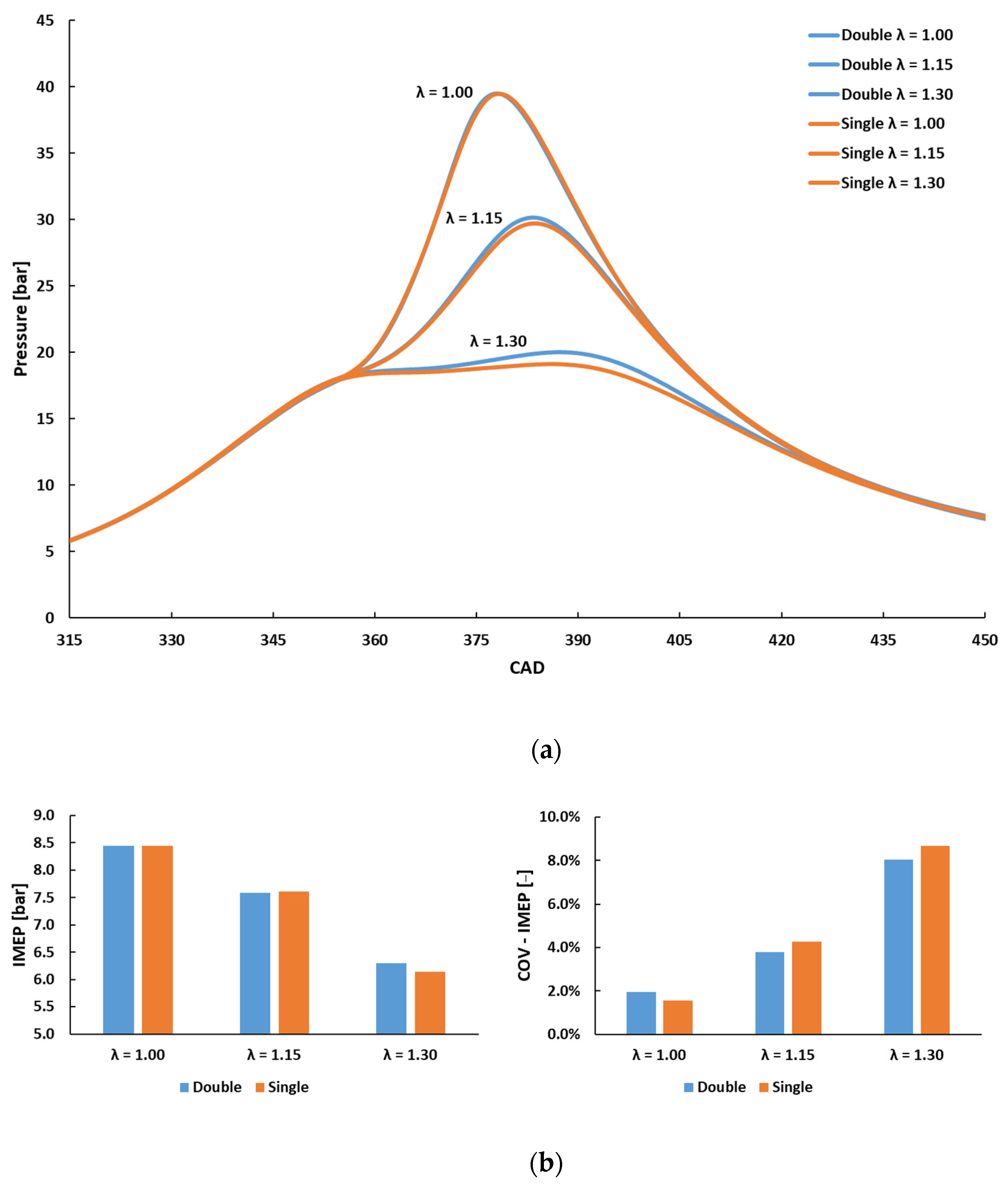
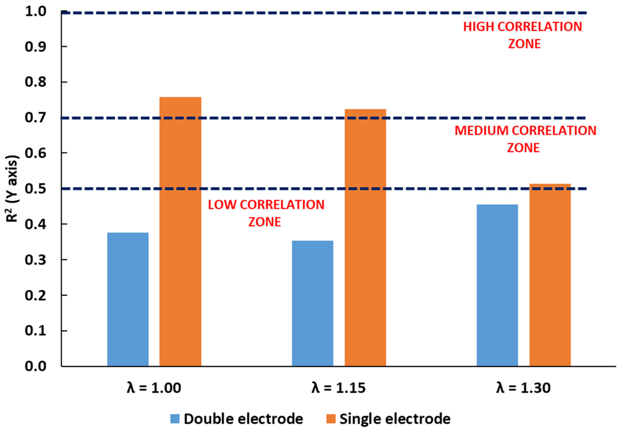
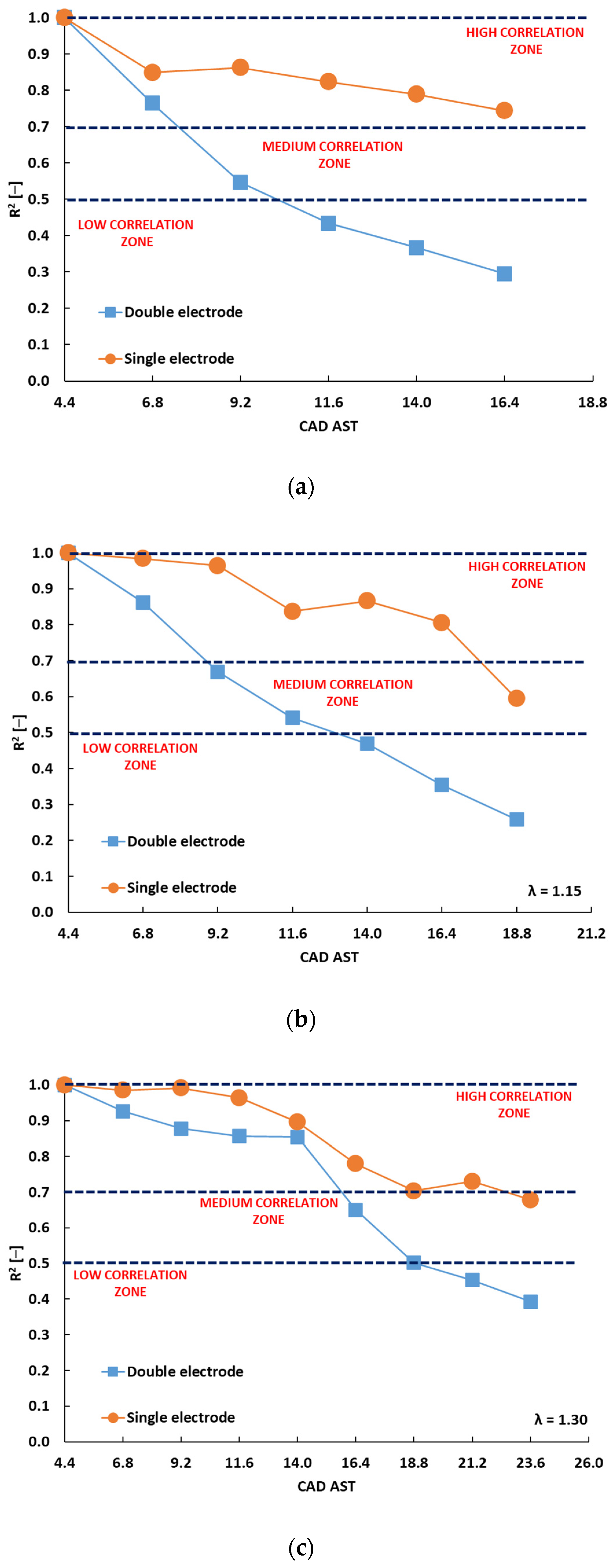
5.1. Cross-Flow Orientation, AFRrel Effect

The cases that featured cross-flow orientation were intended to be “tumble biased”, meaning that the kernel is more exposed to the ordered tumble motion rather than to the effects of randomly directed turbulent motion. Fixed spark timing was chosen so as to initiate the combustion process in the same conditions of fluid motion. Changes in air–fuel ratio were enacted by reducing the injected fuel quantity, while maintaining the same WOT setting. Figure 5 shows the in-cylinder pressure traces and the main engine operating parameters.
The double-electrode spark plug allowed reaching slightly higher peak pressures (i.e., about 0.3 and 1.0 bar difference for AFRrel 1.15 and 1.30, respectively), except for the stoichiometric burn condition, for which no appreciable differences were noted. As expected, increasing the air–fuel ratio resulted in lower IMEP values, with values around 8.4, 7.6, and 6.2 bar for AFRrel 1.00, 1.15, and 1.30, respectively. The IMEP did not show noticeable differences when switching from the double to the single spark plug design, except for the leaner burn condition investigated, wherein a slight increase of 3% in IMEP was noted between the two spark plug designs. The COVIMEP data show that the double-electrode solution ensured a slight improvement in stability for the lean burn condition; except for the stoichiometric case, a reduction of almost one percentage point in terms of COVIMEP was noted compared to the single-electrode type. The combustion phase during flame development featured a CA5 mark of about 14.0 and 18.0 CAD AST for AFRrel 1.00, and 1.15, while for the leanest mixture, a difference of about 0.8 CAD between the two configurations was noted (i.e., 23.6 and 24.4 CAD AST for double- and single-electrode respectively), as to confirm the slower initial combustion phase and thus a longer time of exposition to the turbulent motion and, as a consequence, a higher cyclic variability.
Figure 6 shows the R2 values for the single- and double-ground electrode designs, for the three investigated air–fuel ratios. An evident trend of decreasing R2 with increasing AFRrel values was noted for the single-electrode design, with R2 above 0.7 for the first two settings and slightly above the 0.5 value for the leanest case. On the other hand, for the double-electrode design, no significant correlation between kernel position and flame displacement at CA5 was observed. Given the intended tumble bias, this seems to suggest that only the single-electrode type is, to some extent, sensitive to the effects of this ordered fluid motion.
In addition to the information given by the flame position at the CA5 mark, further useful observations can be made by analysing the evolution of R2 throughout the kernel formation and development. Figure 7a–c show the evolution, as a function of the crank angle after spark timing, of the mean R2 values for three AFRrel cases and the two plug configurations. It is immediately evident that the double-electrode type features a steeper decrease of the correlation parameter, thus explaining the overall figures obtained at CA5. For both spark plugs, the evolution is dilated in time as the air–fuel mixture becomes leaner (please note the different CAD scales for each case when passing from Figure 7a to Figure 7b and then Figure 7c). This can be related to the fact that a leaner mixture results in reduced laminar flame speed and therefore in longer combustion duration, especially in its initial stages. Therefore, the effect of tumble motion is more pronounced compared to stoichiometric conditions (Figure 7a), meaning that displacement along the Y axis is more likely to be governed by the ordered fluid motion when the interaction is lengthened. Slight improvements in mixture homogeneity could be another explanation, since the reduced injected fuel quantity is more likely to lead to lower mixture composition gradients and thus to a lower influence of local laminar flame speed.
As an overall conclusion, for the cross-flow orientation, the single-electrode design seems more likely to show a higher level of correlation between kernel and flame displacement. Moreover, as already highlighted in [16], the lack of a preferential direction for the displacement of the kernel seems to be beneficial in terms of combustion stability, especially for lean mixtures: in other words, the double-electrode geometry, which shows a lower correlation between the initial kernel position and the flame displacement at CA5, is also showing slightly higher peak pressure values and slightly lower COV values for lean mixtures.

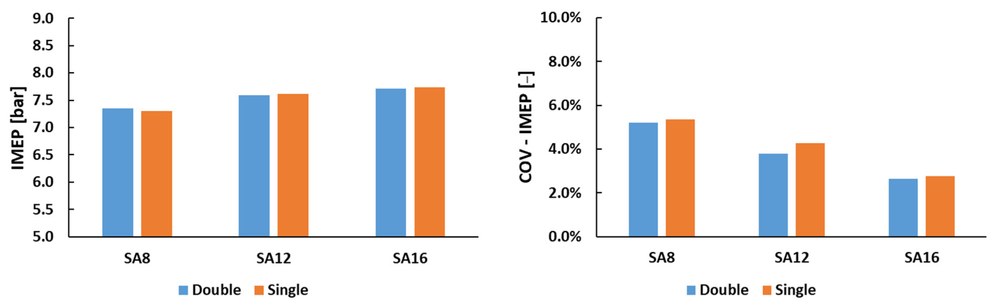
5.2. Crossflow Orientation, Spark-Timing Effect

As reported in the previous sub-section, spark timing was initially fixed to ensure the same fluid motion conditions during ignition. In a second step, the air–fuel ratio was kept constant and spark timing was varied. The AFRrel 1.15 condition was chosen, to allow sweeping the ignition advance in a range that ensured knock-free operation from one side (for more advanced timings) and acceptable combustion stability from the other side (for more retarded timings). For the sake of brevity, Figure 8 shows only the IMEP and COV plots without reporting the mean in-cylinder pressure traces, as these did not show particular trends or differences between spark plug geometries.
In line with the results discussed in the previous sub-section, the IMEP did not show any appreciable difference when switching from one spark plug design to the other. The COVIMEP was lower than 3.0% for SA16, while, when delaying the spark event, the cyclic variability rapidly increased, up to about 5.0% for SA8, although differences in terms of COVIMEP between the two spark plugs were only noticeable for the SA12 timing.
Again, the two plug designs featured opposite trends in terms of correlation between the Y-axis displacement of kernel and flame at CA5, as shown in Figure 9. As expected, only the single-electrode case showed somehow higher correlation values, given that more extensive tumble effects should result in the same displacement direction as that of the organized fluid motion.
Figure 10 shows, for the SA16 case as an example, the R2 evolution as a function of crank angle from spark timing. Again, the single-electrode spark plug design shows an evident sensitivity to the tumble motion, while, for the double-electrode, the correlation is rapidly vanishing.
In conclusion, for the cross-flow orientation and for a given AFRrel value, no significant differences between the two electrode geometries could be highlighted for different spark timings.

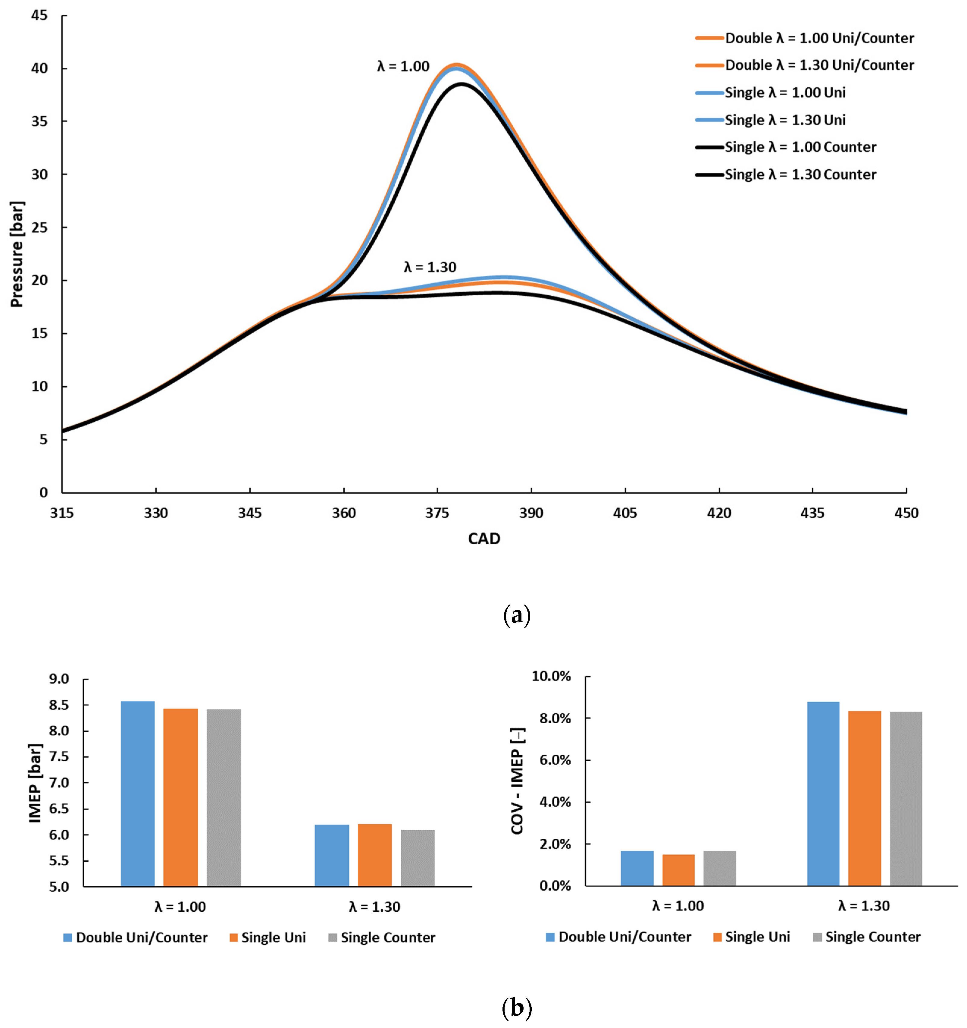
5.3. Uni-Flow and Counter-Flow Orientations

Further investigations were performed by considering the spark plug orientation parallel to the tumble motion corresponding to uni- and counter-flow for the single-electrode and uni-flow for the double-electrode. Looking at Figure 11b, no significant differences were found in terms of IMEP or its COV when changing spark plug orientation. More noticeable changes were recorded for peak pressure (Figure 11a) when comparing the counter-flow condition with double uni-/counter-flow and single uni-flow configurations. In more detail, the former featured lower peak pressure values for each investigated air–fuel ratio (an overall decrease of 1.5–1.8 bar was noted).
Figure 12a shows the mean values of the determination factor R2 and (b) its evolution during the early stage of the combustion process for the stoichiometric and the leaner air–fuel ratio mixture. Starting with Figure 12a, it is possible to note the lack of any significant correlation for all of the cases with this orientation. Moving to Figure 12b,c, just as for the ARFrel sweep, the single-electrode design shows a less steep decrease compared to the double-electrode type. The trend recorded for the counter-flow single-electrode case was closer to the uni-flow double-electrode type but without highlighting any relevant correlation value. On the contrary, the uni-flow orientation for the single-electrode type acts as a shield with respect to direct tumble, ensuring R2 values in the high-correlation region, while the wake downstream of the plug seems to favor early flame propagation.
Finally, as far as the combustion development is concerned, it was noted that, for both air–fuel ratios, the single-electrode design in counter-flow orientation resulted in a slower combustion development compared to the other cases. Differences of about 0.8 and 1.2 CAD at CA5, and of about 1.6 and 2.8 CAD at CA50 for AFRrel 1.00 and 1.30, respectively, were noted. This further emphasizes the different flame–fluid interaction with respect to spark plug design and orientation, as well as the influence this phenomenon exerts on the initial stages of combustion.

6. Conclusions

Using data recorded on an optically accessible DISI engine, this study aimed to understand and correlate the flame kernel formation process with the subsequent flame development for different spark plug geometries and electrode orientations with respect to tumble motion, especially for lean mixtures. While only minor differences were noted in terms of IMEP among all of the configurations under investigation, a slight reduction in CCV when employing double-electrode spark plugs compared to the single-electrode was recorded for the cross-flow orientation for the lean mixtures.
A new parameter was defined for correlating the position where ignition occurs with the subsequent locations of the flame kernel during the first phases of the combustion process, thus allowing the gathering of a better understanding of the interactions between the combustion process and fluid flow characteristics.
The spark plug design and the electrodes’ orientation were shown to influence how the kernel evolves, especially for lean mixtures. The main findings can be summarized as follows:
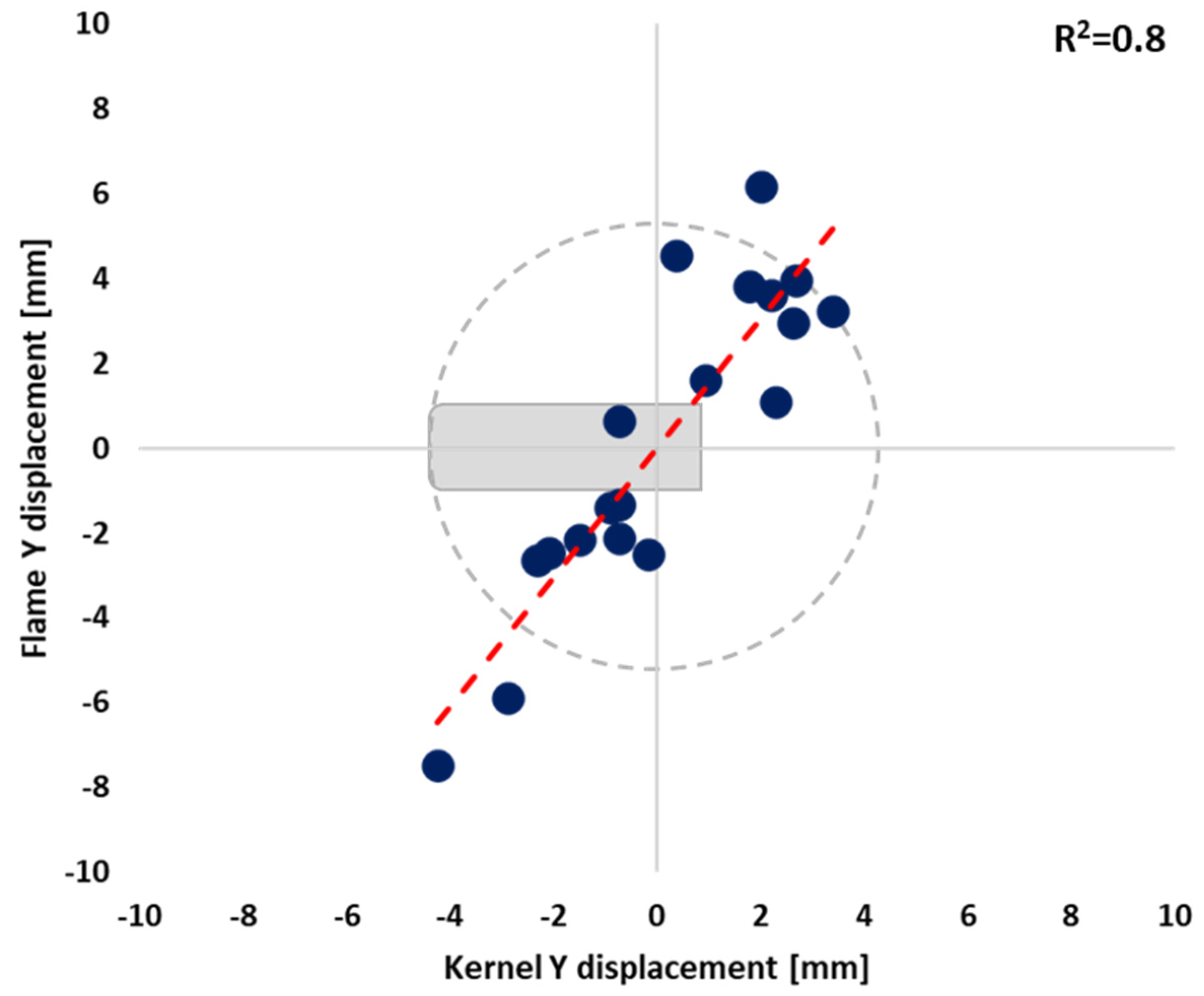
  • For the cross-flow orientation and for all of the three AFRrel investigated, the single-electrode design resulted in higher R2 correlation coefficient values between the initial kernel position and flame displacement at CA5 compared to the double-electrode type, showing a higher sensitivity to the effects of the tumble fluid motion.
  • For the cross-flow orientation, and for the leanest AFRrel investigated, the double-electrode geometry, which showed a lower sensitivity to the effects of the tumble fluid motion, also showed some noticeable improvements in terms of both IMEP and combustion stability in comparison with the single-electrode design.
  • As far as the uni-/counter-flow orientations are concerned, a substantial lack of correlation between initial kernel position and flame displacement at CA5 was found for all electrode geometries and orientations, while some noticeable effects in terms of peak pressure were found only for the single-electrode geometry in counter-flow orientation.
All of these findings emphasize the complexity of the phenomena underlying the flame kernel formation process. If the engine performance parameters appear to be influenced in a minor way, with the only CCV showing a slight reduction when employing the double-electrode spark plug design, the conclusion is quite different from the optical point of view. Moreover, the increasing use of numeric simulation software, then the ever more accurate boundary conditions required to reduce the predicted error between numeric results and experimental measures, leads to the possibility of extending the current study with new operative conditions for building a database on flame kernel characteristics useful for validating CFD codes.

Author Contributions

Conceptualization, S.S.M. and A.I.; methodology, S.S.M. and A.I.; software, A.I., G.C. and L.R.; validation, L.R.; formal analysis, G.C.; investigation, A.I. and G.C.; resources, A.I.; data curation, G.C.; writing—original draft preparation, A.I.; writing—review and editing, A.I., L.R. and F.M.; visualization, S.S.M.; supervision, S.S.M. and F.M.; project administration, S.S.M. and F.M. All authors have read and agreed to the published version of the manuscript.

Funding

This research received no external funding.

Institutional Review Board Statement

Not applicable.

Conflicts of Interest

The authors declare no conflict of interest.

Abbreviations

λLambda
AFRrelAir—fuel relative ratio
ASTAfter spark timing
ATDCAfter top dead centre
BTDCBefore top dead centre
CA5Crank angle at 5% of burned mass fraction
CA50Crank angle at 50% of burned mass fraction
CADCrank angle degree
CCVCycle to cycle variability
COVCoefficient of variation
DIDirect injection
DISIDirect-injection spark ignition
ETUEngine timing unit
EVCExhaust valve closing
EVOExhaust valve opening
FFTFast Fourier transform
GDIGasoline direct injection
HRRHeat release rate
ICEInternal combustion engine
IMEPIndicated mean effective pressure
IVCIntake valve closure
IVOIntake valve opening
LCLuminous centroid
MFBMass fraction burned
SASpark advance
SISpark ignition
SOIStart of injection
STSpark timing
TDCTop dead centre
UEGOUniversal exhaust gas oxygen
WGWall-guided
WOTWide open throttle

References

  1. Global Climate Change, Vital Signs of the Planet. Available online: https://climate.nasa.gov/effects/ (accessed on 15 February 2022).
  2. Lawrence, J.; Blackett, P.; Cradock-Henry, N.A. Cascading climate change impacts and implications. Clim. Risk Manag. 2020, 29, 100234. [Google Scholar] [CrossRef]
  3. European Green Deal: Commission PROPOSES transformation of EU Economy and Society to Meet Climate Ambitions. Available online: https://ec.europa.eu/commission/presscorner/detail/en/IP_21_3541 (accessed on 15 February 2022).
  4. World Resource Institute: COP26: Key Outcomes from the UN Climate Talks in Glasgow. Available online: https://www.wri.org/insights/cop26-key-outcomes-un-climate-talks-glasgow (accessed on 15 February 2022).
  5. Santos, N.D.S.A.; Roso, V.R.; Malaquias, A.C.T.; Baêta, J.G.C. Internal combustion engines and biofuels: Examining why this robust combination should not be ignored for future sustainable transportation. Renew. Sustain. Energy Rev. 2021, 148, 111292. [Google Scholar] [CrossRef]
  6. Conway, G.; Joshi, A.; Leach, F.; García, A.; Senecal, P.K. A review of current and future powertrain technologies and trends in 2020. Transp. Eng. 2021, 5, 100080. [Google Scholar] [CrossRef]
  7. Towoju, O.A. Fuels for Automobiles: The Sustainable Future. J. Energy Res. Rev. 2021, 7, 8–13. [Google Scholar] [CrossRef]
  8. Li, Q.; Liu, J.; Fu, J.; Zhou, X.; Liao, C. Comparative study on the pumping losses between continuous variable valve lift (CVVL) engine and variable valve timing (VVT) engine. Appl. Therm. Eng. 2018, 137, 710–720. [Google Scholar] [CrossRef]
  9. Liu, Q.; Liu, J.; Fu, J.; Li, Y.; Luo, B.; Zhan, Z.; Deng, B. Comparative study on combustion and thermodynamics performance of gasoline direct injection (GDI) engine under cold start and warm-up NEDC. Energy Convers. Manag. 2018, 181, 663–673. [Google Scholar] [CrossRef]
  10. Wei, H.; Yu, J.; Shao, A.; Zhou, L.; Hua, J.; Feng, D. Influence of injection strategies on knock resistance and combustion characteristics in a DISI engine. Proc. Inst. Mech. Eng. Part D J. Automob. Eng. 2018, 233, 2637–2649. [Google Scholar] [CrossRef]
  11. Rapp, V.; Killingsworth, N.; Therkelsen, P.; Evans, R. Lean-Burn Internal Combustion Engines; Academic Press: Cambridge, MA, USA, 2016; pp. 111–146. [Google Scholar] [CrossRef]
  12. Kalwar, A.; Agarwal, A.K. Lean-Burn Combustion in Direct-Injection Spark-Ignition Engines. In Alternative Fuels and Advanced Combustion Techniques as Sustainable Solutions for Internal Combustion Engines; Springer: Singapore, 2021; pp. 281–317. [Google Scholar] [CrossRef]
  13. Gong, C.; Si, X.; Liu, F. Comparative analysis on combustion and emissions between CO2 and EGR dilution GDI engine at half-load, stoichiometric and lean-burn conditions. Fuel 2021, 309, 122216. [Google Scholar] [CrossRef]
  14. Hattori, H.; Sogawa, Y.; Yanagisawa, N.; Hosoya, M.; Shoji, T.; Iwakiri, Y.; Yamashita, T.; Ikeda, T.; Tanaka, S.; Takahashi, K.; et al. Unregulated Emissions Evaluation of Gasoline Combustion Systems (Lean Burn/Stoichiometric DISI and MPI), State of the Art Diesel Aftertreatment Technologies (DPF, urea-SCR and DOC), and Fuel Qualities Effects (EtOH, ETBE, Aromatics and FAME); SAE Technical Paper; SAE International: Warrendale, PA, USA, 2007. [Google Scholar] [CrossRef]
  15. Scarcelli, R.; Richards, K.; Pomraning, E.; Senecal, P.K.; Wallner, T.; Sevik, J. Cycle-to-Cycle Variations in Multi-Cycle Engine RANS Simulations; SAE Technical Paper; SAE International: Warrendale, PA, USA, 2016. [Google Scholar] [CrossRef]
  16. Zhao, L.; Moiz, A.A.; Som, S.; Fogla, N.; Bybee, M.; Wahiduzzaman, S.; Mirzaeian, M.; Millo, F.; Kodavasal, J. Examining the role of flame topologies and in-cylinder flow fields on cyclic variability in spark-ignited engines using large-eddy simulation. Int. J. Engine Res. 2017, 19, 886–904. [Google Scholar] [CrossRef]
  17. Wadekar, S.; Janas, P.; Oevermann, M. Large-eddy simulation study of combustion cyclic variation in a lean-burn spark ignition engine. Appl. Energy 2019, 255, 113812. [Google Scholar] [CrossRef]
  18. Van Dam, N.; Sjöberg, M.; Som, S. Large-Eddy Simulations of Spray Variability Effects on Flow Variability in a Direct-Injection Spark-Ignition Engine Under Non-Combusting Operating Conditions; SAE Technical Paper; SAE International: Warrendale, PA, USA, 2018. [Google Scholar] [CrossRef] [Green Version]
  19. Sjerić, M.; Kozarac, D.; Tatschl, R. Modelling of early flame kernel growth towards a better understanding of cyclic combustion variability in SI engines. Energy Convers. Manag. 2015, 103, 895–909. [Google Scholar] [CrossRef]
  20. Pera, C.; Knop, V.; Reveillon, J. Influence of flow and ignition fluctuations on cycle-to-cycle variations in early flame kernel growth. Proc. Combust. Inst. 2015, 35, 2897–2905. [Google Scholar] [CrossRef]
  21. Irimescu, A.; Marchitto, L.; Merola, S.S.; Tornatore, C.; Valentino, G. Evaluation of different methods for combined thermodynamic and optical analysis of combustion in spark ignition engines. Energy Convers. Manag. 2014, 87, 914–927. [Google Scholar] [CrossRef]
  22. Martinez, S.; Irimescu, A.; Merola, S.S.; Lacava, P.; Curto-Riso, P. Flame Front Propagation in an Optical GDI Engine under Stoichiometric and Lean Burn Conditions. Energies 2017, 10, 1337. [Google Scholar] [CrossRef] [Green Version]
  23. Irimescu, A.; Merola, S.S.; Martinez, S. Influence of Engine Speed and Injection Phasing on Lean Combustion for Different Dilution Rates in an Optically Accessible Wall-Guided Spark Ignition Engine. SAE Int. J. Engines 2018, 11, 1343–1369. [Google Scholar] [CrossRef]
  24. Schirru, A.; Irimescu, A.; Merola, S.; d’Adamo, A.; Fontanesi, S. Flame Kernel Growth and Related Effects of Spark Plug Elec-trodes: Fluid Motion Interaction in an Optically Accessible DISI Engine. World Acad. Sci. Eng. Tech-Nology Int. J. Mech. Mechatron. Eng. 2020, 14, 95–103. [Google Scholar] [CrossRef]
  25. Geiger, J.; Pischinger, S.; Böwing, R.; Koß, H.-J.; Thiemann, J. Ignition Systems for Highly Diluted Mixtures in SI-Engines. SAE Trans. 1999, 108, 1099–1110. [Google Scholar] [CrossRef]
  26. Lee, Y.G.; Grimes, D.A.; Boehler, J.T.; Sparrow, J.; Flavin, C. A Study of the Effects of Spark Plug Electrode Design on 4-Cycle Spark-Ignition Engine Performance; SAE Technical Paper; SAE International: Warrendale, PA, USA, 2000. [Google Scholar] [CrossRef]
  27. Heywood, J.B. Internal Combustion Engine Fundamentals; McGraw Hill: New York, NY, USA, 1988. [Google Scholar]
Figure 1. Experimental setup (top left), detailed sketch of the elongated piston (top right), spark plug orientations investigated (bottom left), and detailed sketch for the single electrode spark plug in counterflow configuration (bottom right).
Energies 15 03393 g001
Figure 2. (a) Sequence of steps applied for image processing: (A) original raw data, (B) circular mask and gamma/brightness improvement, (C) image binarization, (D) FFT correction. (b) Flame area morphologic details.
Energies 15 03393 g002aEnergies 15 03393 g002b
Figure 3. Selected images detected during the kernel phase (4.4 CAD AST) and CA5 (corresponding to 16.4 CAD AST) for the case of a single-electrode design in cross-flow orientation (λ 1.15, SA 12 CAD).
Energies 15 03393 g003
Figure 4. Comparison between the displacement along the direct tumble direction of the kernel and CA5 flames for the case of a single-electrode plug in cross-flow orientation (λ = 1.15, SA = 12 CAD; the electrode is shown on the graph for scaling purpose only).
Energies 15 03393 g004
Figure 5. (a) In-cylinder pressure traces (top) and (b) mean IMEP and COV values for both spark plug designs and cross-flow orientation (AFRrel 1.00–1.15–1.30, SA 12 CAD).
Energies 15 03393 g005
Figure 6. Coefficient of determination R2 of the linear fit between kernel position and flame displacement at CA5 for cross-flow orientation, different AFRrel values, and fixed spark advance (12 CA).
Energies 15 03393 g006
Figure 7. Evolution of the coefficient of determination R2 of the linear fit between kernel position and flame displacement at CA5 during the early stages of combustion for the cross-flow orientation for the stoichiometric AFRrel value (a), for AFRrel 1.15 (b), and for AFRrel 1.30 (c). For all of the above reported cases, the spark advance was fixed at 12 CA.
Energies 15 03393 g007
Figure 8. IMEP and COVIMEP for both spark plug electrode designs and cross-flow orientation (AFRrel 1.15, SA 8–12–16 CAD).
Energies 15 03393 g008
Figure 9. Coefficient of determination R2 of linear fit between the Y-axis displacement of kernel and flame at CA 5 for the cross-flow orientation for different spark advances and fixed AFRrel (1.15).
Energies 15 03393 g009
Figure 10. Evolution of the coefficient of determination R2 of the linear fit between kernel position and flame displacement at CA5 during the early stages of combustion during the early stages of the combustion process for the cross-flow orientation at fixed SA (16 CAD) and AFRrel (1.15).
Energies 15 03393 g010
Figure 11. (a) In-cylinder pressure traces (top) and (b) mean IMEP and COV values for both spark plug designs and uni-/counter-flow orientations (λ = 1.00–1.30, SA 12 CAD).
Energies 15 03393 g011
Figure 12. (a) Coefficient of determination R2 of linear fit between the Y-axis displacement of kernel and flame at CA5 for different orientations. (b,c): Evolution of R2 (along the Y axis) during the early stages of the combustion process for different spark orientations at 1.00 (middle) and 1.30 AFRrel (bottom).
Energies 15 03393 g012
Table 1. Engine specifications.
ParameterDescription
Displacement399 cm3
Stroke81.3 mm
Bore79 mm
Connecting rod143 mm
Compression ratio10:1
Number of valves4
Exhaust valves opening153 CAD ATDC
Exhaust valves closing360 CAD ATDC
Intake valves opening363 CAD BTDC
Intake valves closing144 CAD BTDC
Fuel injection systemDI WG
Start of injection300 CAD BTDC
Table 2. Operating conditions.
Spark Plug DesignOrientationSpark Advance [CAD BTDC]λ
Single-electrodeCross-flow81.15
121.00
1.15
1.30
161.15
Uni-flow121.00
1.30
Counter-flow121.00
1.30
Double-electrodeCross-flow81.15
121.00
1.15
1.30
161.15
Uni-flow121.00
1.30
Publisher’s Note: MDPI stays neutral with regard to jurisdictional claims in published maps and institutional affiliations.

