Abstract
To improve the aerodynamic performance and reduce the noise of multi-blade centrifugal fans used in air conditioners, a bionic groove structure was introduced into the blade tip design, inspired by the drag reduction characteristics of mantis shrimp. In this paper, the numerical method was used to investigate the effects of a blade tip bionic groove on the aerodynamic performance and noise characteristics of a multi-blade centrifugal fan. Firstly, the basic design parameters, such as groove width, groove depth, groove center distance, and groove number, were selected to define the shape of the blade tip bionic groove. Then, the effect of the design parameters on the aerodynamic performance of the multi-blade centrifugal fan was studied. Finally, the multi-blade centrifugal fan models with different groove shapes, such as rectangular bionic grooves, circular bionic grooves, and triangular bionic grooves, were established to compare the influence of blade tip groove structures on the aerodynamic performance of the multi-blade centrifugal fan. Through analysis of the aerodynamic performance and noise characteristics of the multi-blade centrifugal fan and the flow fields in the fan impeller, the flow control mechanism of the blade tip bionic groove was revealed. The results showed that the triangular bionic groove on the blade tip had a certain noise reduction effect, although the structural parameters of the bionic groove had little effect on the aerodynamic performance of the multi-blade centrifugal fan. This is because the triangular bionic groove structure can effectively inhibit the vortex shedding at the trailing edge of blade and reduce the flow separation in the impeller passages. As a result, the velocity distribution at the impeller tip became more uniform and the intensity of the tip vortex and the shedding vortex was weakened. Correspondingly, the noise of multi-blade centrifugal fan was also reduced to some extent.
1. Introduction
Multi-blade centrifugal fans are widely used in household appliances, such as air conditioners and range hoods, because of their low noise, large volume flow rate, and simple structure. In recent years, with the improvement of living standards, people have higher and higher requirements for human comfort and noise under the operation of household appliances. As the key component of these kinds of household appliances, the study and improvement of the aerodynamic performance and noise characteristics of multi-blade centrifugal fans is of great significance.
In the early years, Neise [1] performed a large number of experimental studies on fan noise reduction, such as changing the volute tongue clearance, using a staggered impeller, matching the acoustic impedance of fans and pipeline systems, and others to reduce the noise of centrifugal fans. With the deepening of noise reduction research, it is difficult to achieve satisfactory results by only changing the structural parameters of the fan. In 1996, Gad-el-Hak [2] found that it is possible to manipulate a flow field to effect a desired change to optimize the flow field and create good performance characteristics. As for multi-blade centrifugal fans, flow control is beneficial for internal flow field optimization and hence improvement of their aerodynamic performance and noise characteristics. The techniques that have been used to manipulate the boundary layer to decrease the drag and separation delay are all related to flow control [3]. Flow control can be divided into two categories: active and passive. One of the most favorable classification schemes of flow control methods considers energy expenditure and control loops involved. The passive control techniques require no auxiliary power and no control loop, while the active techniques still require energy expenditure [4]. Over the recent years, various techniques have been developed to control the separation of airfoil or blade, including both active methods [5,6], such as surface heating or cooling, suction, and acoustic excitation, as well as passive methods that include roughness, shaping, and turbulators. Across all the flow control methods, passive techniques, especially grooves on the airfoil or blade surface, are appreciated due to their low cost and no additional energy consumption [7,8]. Additionally, the emergence of the concept of bionic noise reduction provides a new research direction for the groove passive flow control and hence, the small-scale bionic groove structure, as the passive flow control method is widely adopted in research [9,10,11].
Zhu et al. [12] reviewed the passive flow control technologies that are in use or worth using in straight blade vertical axial wind turbines. Additionally, the research prospect of the Gurney flap, dimple, and other technologies were presented. Shukla et al. [13] studied the effects of Gurney flap, inward dimple, and the combination of both Gurney flap and dimple on the straight blades of vertical axis wind turbines. It was found that the Gurney flap, inward dimple, and the combination of the two improved the performance of NACA 0012 and NACA 0015 with respect to lift coefficient and velocity. Robarge et al. [14] investigated the best location, depth, and length of groove and tested it on a NACA 0015 airfoil. The test results showed that the addition of optimized grooves eliminated the separation bubbles behind the grooves. Dai et al. [15] extracted the surface features of whale skin and established a centrifugal pump model with surface V-shape grooved blades. The bionic grooved surface could change the vortex structure in the impeller passages, reduce the sound power, and therefore reduce the total sound pressure level of the bionic blade. Ye et al. [16] found that the efficiency of an axial flow fan with different grooved blade tips was improved when compared to the original fan, and leakage loss was reduced; however, the noise of the axial flow fan was increased. Inspired by [16], Kharati-Koopaee and Moallemi [17] performed further study where the efficiency changes of an axial flow fan with a single grooved tip and an axial flow fan with a double grooved tip were evaluated. Finally, they found that the grooved tip could increase the efficiency, and the effect of the single grooved tip was better.
The marine living environment is complex, which requires marine creatures to have the ability to adapt to the environment. Different creatures evolve different adaptive structures or functions in combination with the external environment and their own forms. These specific structures or functions can also inspire researchers when studying bionic noise reduction. Kodama et al. [18] studied the living habits of mantis shrimp and found that the abdominal groove structure of the mantis shrimp can effectively reduce the resistance when they swim in the water and improve the streamline state on its surface. These structures make the velocity change on its body surface more uniform, so as to accelerate and stabilize their swimming.
Inspired by the drag reduction characteristics of mantis shrimp and small-scale groove passive flow control, a bionic grooved structure on the blade tip, based on the abdominal groove of mantis shrimp, is proposed to solve the problem of vortexes at the collector gap of multi-blade centrifugal fans. The groove structure is used to optimize the streamline state and improve the uniformity of velocity distribution of the impeller tip. Additionally, the influence of the bionic groove structure on the aerodynamic performance and noise characteristics of a multi-blade centrifugal fan is summarized in this paper. The noise reduction mechanism of the blade tip bionic groove will provide a significant reference for the optimal design and performance improvement of multi-blade centrifugal fans.
2. Research Object and Methods
2.1. Computational Domain Model
2.1.1. Governing Equation
The numerical calculation method used in this paper consisted of three parts: steady, unsteady, and noise calculation. The steady calculation is based on a multiple reference frame (MRF) model. The unsteady calculation takes the convergence results of the steady calculation as the initial value. Here, the problem of temporal correlation is solved by using the mesh motion model of the sliding-mesh technique in the rotating centrifugal fan. In the noise calculation, which is based on the unsteady characteristics of the flow field, the convergence results of the unsteady calculation is used as the input for the FW-H acoustic equation to calculate the noise and predict the acoustic characteristics of the multi-blade centrifugal fan. Because the viscous friction coefficient of the inner wall of the multi-blade centrifugal fan is small and the relative speed is low, the wall friction heat can be ignored. Therefore, the energy equation was not considered in the calculation [19].
The flow velocity of the multi-blade centrifugal fan is low, and the flow can be considered to be incompressible, which means the fluid density is a constant. So in the governing equations, the mass conservation equation can be expressed as:
where, is the fluid velocity component in the direction .
The momentum conservation equation can be expressed as:
where is the fluid density, is the time average pressure, and and represent the pulsating velocity, which is obtained by subtracting the time average velocity from the instantaneous velocity. The second-order correlation term is called Reynolds stress.
In a realizable k–ε model, the transmission equation of k and ε is:
In Equations (3) and (4), represents the turbulent kinetic energy generation term due to the velocity gradient. are the turbulent Prandtl numbers of k and ε, respectively, and and . and are constant and and .
Here,
The FW-H acoustic equation is used for acoustic calculation, and its solution process is based on [20,21]. The FW-H equation is reorganized into Navier–Stokes equation in the form of wave equation by introducing generalized function, which is the most common form of acoustic analogy. The equation can be written as follows:
where is the far-field sound velocity and is the far-field sound pressure. is the assumed surface embedded in the unbounded internal flow field (). is the fluid velocity component perpendicular to the surface , and is the surface velocity component perpendicular to the surface . is the density of steady flow field. is the Dirac function, and is the Heaviside function. and are the compressible stress tensor and Lighthill stress tensor, respectively, and they can be expressed as Equations (7) and (8), where is the Kronecker Delta.
2.1.2. Computational Domain
The double suction multi-blade centrifugal fan of the coil unit in air conditioning systems was taken as the research object. The air flow enters axially from both sides of the multi-blade centrifugal fan and flows out along the circumference of the impeller after performing work through the blades. The multi-blade centrifugal fan is composed of a collector, a volute, and an impeller. The impeller is forward curved and its number of blades is 44. The impeller is equipped with a middle plate, and the width ratio of the impeller on both sides of plate is 1:1. The impeller on both sides is installed with staggered teeth. The rotating speed is 1120 r/min under rated working conditions. The volute profile is composed of three circular arcs. The inlet collector is circular and integrated with the volute. The physical model of the double suction multi-blade centrifugal fan is shown in Figure 1. According to the physical model, the parametric model of the computational domain including the impeller, volute, and inlet/outlet extension section was established, as shown in Figure 2. The inlet/outlet extension section refers to the computational domain, which was formed by extending the inlet upstream to twice the impeller’s outer diameter and extending the outlet downstream to twice the impeller’s outer diameter. Its purpose was to accelerate the calculation’s convergence. Each part of the computational domain was connected through the interface for data transmission.
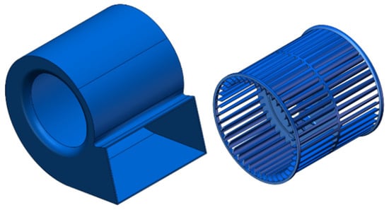
Figure 1.
Physical model of multi-blade centrifugal fan.
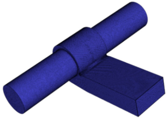
Figure 2.
Parametric model of computational domain.
2.1.3. Turbulence Model and Boundary Conditions
The turbulence model adopted the realizable k–ε model, which has a good ability to simulate rotating flow [22]. For turbulent boundary conditions, turbulent kinetic energy k and turbulent dissipation rate ε can be calculated by the following formula:
Here, is the mean inlet velocity and is the dynamic viscosity. is the turbulence intensity, which is calculated by the Reynolds number by the following formula:
In Equation (11), the Reynolds number can be calculated by the following formula:
Here, and are the fluid density and viscosity, is the characteristic velocity, and is the characteristic length. In this paper, the = 30,306, and the flow is a fully turbulent flow over the entire blade [23]. In the realizable k–ε model, is defined as:
In Equation (13), , is calculated as follows:
For the irrotational flow, the second term in the root sign of is 0, which is specially used to represent the influence of rotation [24]. is determined as:
Here, refers to the strain rate. represents the normal direction of the stress component plane and represents the direction of the stress component. For unsteady calculation, the time step is determined by the following formula:
where is the maximum number of iterative steps in each time step. is impeller rotating speed and is the number of impeller blades. The unsteady calculation time step is about 3.577 × 10⁻⁵ s. According to the actual operating conditions of multi-blade centrifugal fan, its internal flow Mach number is less than 0.3, which can be regarded as incompressible flow [25]. For incompressible flow, the density is constant and does not change with time and space, kg/m³. ANSYS Fluent was used for numerical simulation. The steady calculation adopted the realizable k–ε model and standard wall functions. Table 1 shows the initial and boundary conditions used in the numerical models.

Table 1.
The Initial and Boundary Conditions.
In the unsteady calculation, the transient formulation adopts a second-order implicit scheme, and the boundary conditions are consistent with the steady calculation.
2.2. Grid Independence Test
The computational domain of the multi-blade centrifugal fan was composed of the volute, impeller, and inlet/outlet area. Considering its structure, an unstructured grid with strong adaptability to complex boundaries was used to discretize the computational domain. In addition to being able to better adapt to complex boundaries, an unstructured grid also has the characteristics of easy implementation, short time consumption, and low cost. Reasonable grid distribution is very important to accurately capture flow field structure and noise field characteristics. During the meshing, the leading edge of the blade, volute tongue, and collector were partly densified to ensure that the value of the overall grid was set in the range of 30–100. In order to ensure the effectiveness and accuracy of the numerical simulation, the number of nodes and volume flow rate of the multi-blade centrifugal fan were selected as independent variables and response results, respectively, so as to complete the grid independence test. As shown in Figure 3, when the number of nodes was approximately 6.6 million, an increase in grid node number did not lead to significant changes in the volume flow rate. It was considered that the number of nodes met the test of grid independence. Finally, the total number of nodes in the computational domain was selected as 6.62 million.
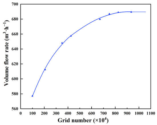
Figure 3.
Grid independence test.
2.3. Validation of Numerical Method
2.3.1. Aerodynamic Performance
The effectiveness of the calculation method was verified by monitoring the numerical outlet volume flow rate and comparing the experimental results. The aerodynamic performance test was conducted in accordance with standard GB/T 1236-2000. The test system was mainly composed of the tested fan, air chamber, multiple nozzle groups, temperature sensor, differential pressure transmitter, auxiliary fan, and data acquisition and processing system. The installation of the tested fan is shown in Figure 4. The tested fan was placed at the inlet of the system, and the auxiliary fan was installed at the outlet of the system. Multiple nozzle groups were used in the air chamber, and a rectifier grid was also installed to produce uniform and stable flow. The working point of the tested fan was controlled by the throttling device of the auxiliary fan. An alternating current motor was used in the experiment, the appropriate nozzle diameter was selected, and the experimental data in the whole working condition range were tested by adjusting the static pressure at the outlet of the fan. Finally, the experimental data obtained by the acquisition system were analyzed and processed by the data processing software. Comparing the numerical results and the experimental test results of the original fan under rated working condition, the outlet volume flow rates were 676.8 m³/h and 719 m³/h, respectively. The relative error was about 5.8%.
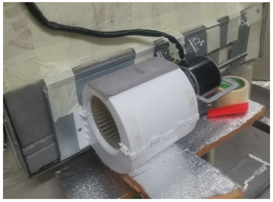
Figure 4.
Installation of the tested fan.
2.3.2. Aerodynamic Noise
The indoor sound pressure sensor was calibrated by the sound calibrator before the noise test. The test background noise was 17.0 dB, which is lower than the noise of the tested fan. The acoustic measuring system met the GB/T 7725-2004 standard. As shown in Figure 5, the acoustic measuring system was composed of the tested multi-blade centrifugal fan, sound pressure sensor, preamplifier, and the data acquisition and noise analysis system. The spherical envelope method, as shown in Figure 6, was used to measure noise. The tested multi-blade centrifugal fan was placed in the center of the semi-anechoic chamber, and the microphone (A–D) was placed 1 m below the tested fan to accurately receive the noise signal. The sound pressure was measured using the sound pressure sensor. The sound pressure was transmitted to data acquisition system through preamplifier. Then, the experimental data were processed by vibration and noise analysis software to obtain the noise characteristics. In the noise calculation, the spherical envelope method was also used to monitor the noise change. The sound pressure levels (SPL) obtained from experimental measurement and numerical calculation were 49.2 dB and 48.8 dB respectively, with a difference of 0.4 dB. In the noise numerical calculation, only aerodynamic noise was considered. Because the mechanical noise and electromagnetic noise were ignored, the noise obtained with the numerical simulation was lower than that obtained with the experimental measurement.
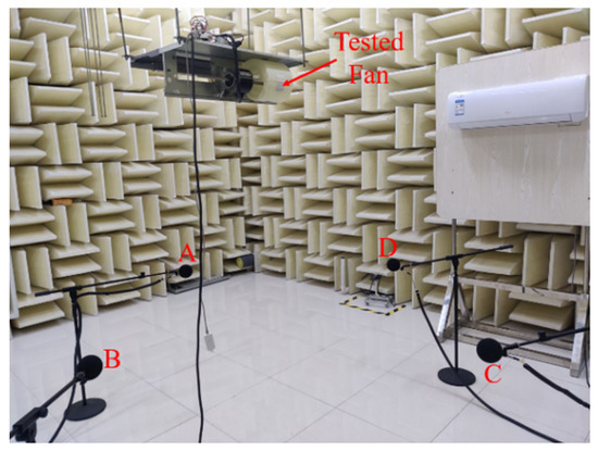
Figure 5.
Acoustic measuring system and microphone A–D.
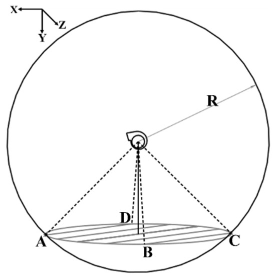
Figure 6.
Spherical envelope method and corresponding test points of microphone A–D.
Based on the comparison of numerical and experimental results, the computational model and numerical method presented in this study can be used to predict the aerodynamic performance and noise characteristics of multi-blade centrifugal fan.
2.4. Blade Tip Bionic Groove
As shown in Figure 7, the back and abdomen of mantis shrimp are flat; the back armor is small, but the segmentation is clear. The lower part of the limb has a plurality of continuous abdominal segments, and a surface groove structure is formed between the segments. This is their natural structure, which has been evolved to avoid predators. With the help of the groove structure, the mantis shrimp can swim quickly and reduce the water fluctuation caused by swimming, i.e., the resistance during swimming is reduced. Research has shown that the non-smooth groove structure on the body surface of mantis shrimp is the main reason for their characteristic form of swimming [26,27]. These groove structures can effectively reduce the resistance of swimming in the water and reduce the pressure pulsation. Additionally, the groove structures can be combined with the body surface, improving the streamline state of the surface and reducing the velocity gradient. Thus, this could make the velocity change on the body surface more uniform, so as to reduce the pressure pulsation and resistance caused by the gradient change and accelerate and stabilize the swimming of mantis shrimp.
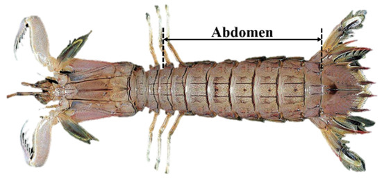
Figure 7.
Mantis shrimp.
There is an axial clearance between the outlet of the collector and the impeller tip. The inlet air flows to the impeller after passing through the collector. Part of the air flow first contacts the impeller tip, which has an impact on the impeller tip and affects the inlet state. In addition, under the combined effect of the pressure difference and circumferential velocity, a three-dimensional tip leakage flow is formed at the axial clearance. The combined effect of impact and leakage flow makes the flow state at the impeller tip complex and the velocity gradient large. In order to reduce the impact effect and the leakage flow and optimize the flow state at the impeller tip, the surface groove of mantis shrimp is taken as the bionic prototype to design and study the structure of the blade tip bionic groove. The blade tip bionic non-smooth groove is constructed by extracting the parameters such as groove width, groove depth, and groove center distance of the mantis shrimp body surface.
2.4.1. Basic Parameters
The basic parameters of the blade tip bionic groove are determined as the shape parameters of groove (SPG) and the number parameters of groove (NPG). The parameters, such as groove width W, groove depth H, and groove center distance L, are selected to define a single groove, and these parameters are the SPG. The groove number, N, is NPG. As shown in Figure 8, the groove width, W, determines the width of a single groove. The groove depth, H, determines the height from the bottom of the groove to the blade tip, and the spacing between two adjacent grooves is determined by the groove center distance, L. According to the structure and parameters of the impeller, and are taken where refers to the height of one side blade. The groove number, N, decreases gradually from the maximum number that can be accommodated at the blade tip.
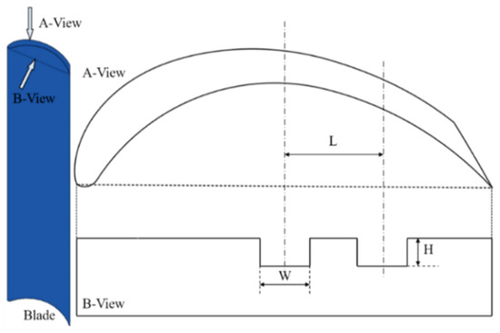
Figure 8.
Basic parameters of bionic groove.
2.4.2. Construction Method
According to the SPG, the impeller was grooved with bionic grooves on the blade tip, as shown in Figure 9. The specific construction method was as follows [28].
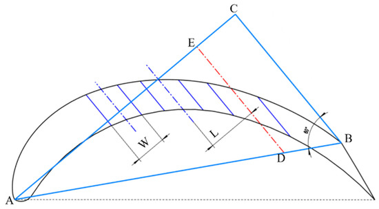
Figure 9.
Construction method of bionic groove. Point A at leading edge of blade, point B at trailing edge of blade, point C at the triangle intersect edges, point D at the oblique edge and point E at one of the triangle edge.
(1) Connect point A at the leading edge of blade and point B at the trailing edge of blade suction surface and make a right triangle on the side of the blade profile with the edge AB as the oblique edge, so that the angle between edge AB and AC is equal to 30°. The other two edges of right triangle intersect at point C.
(2) Make a line, DE, which is parallel to BC in the direction from the trailing edge of blade to the leading edge of blade, and intersect BA at point D, and intersect CA at point E. The distance between BC and DE is the groove center distance, L. Similarly, continue to make a parallel line with L until near the leading edge of blade, which should not be damaged.
(3) Take the center line of each groove as the central axis, and determine the groove width and depth according to the groove width, W, and groove depth, H.
According to the construction method, the parameter of a single blade tip bionic groove can be completely determined. In the presented study, the effects of SPG and NPG on fan performance were observed firstly for the multi-blade centrifugal fan with rectangular bionic grooves (RBGs). Secondly, the aerodynamic performance and noise characteristics of the multi-blade centrifugal fan with RBG, circular bionic groove (CBG), and triangular bionic grooves (TBGs) were studied and compared with the original fan. Figure 10 shows the parametric model of the blade tip of original fan and grooved blade tips with RBGs, CBGs, and TBGs.
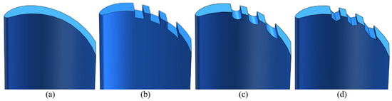
Figure 10.
Parametric model of blade tip with different grooved shapes: (a) blade tip of original fan, (b) blade tip with RBGs, (c) blade tip with CBGs, and (d) blade tip with TBGs.
3. Numerical Results and Discussion
3.1. Aerodynamic Performance
3.1.1. External Characteristic
The volume flow rate and efficiency of the multi-blade centrifugal fan were taken into account to investigate the variance of fan aerodynamic performance, and the efficiency can be calculated as the following equation:
where is the total pressure of the fan outlet, is the volume flow rate, n is the rotating speed, and T is the torque coefficient.
(1) Groove width, W
Two aspects were considered when selecting the value of W. There are some problems that can occur if W is too large: First, the solid area of the blade is reduced, and the strength of blade tip is weakened. Second, a larger flow area for the tip leakage flow may be provided and thus, the noise is aggravated. As shown in Figure 11, with the increase in W, the aerodynamic performance of the multi-blade centrifugal fan decreased and the change in the trend between the volume flow rate and efficiency was approximately linear. When H and L remained unchanged and W increased, the pressure difference between the pressure surface and the suction surface decreased, and the blade work area decreased, resulting in the decline of volume flow rate and efficiency.
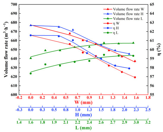
Figure 11.
Aerodynamic performance varies with change to basic parameters.
(2) Groove depth, H
In Figure 11, it can be observed that the fan performance decreased with the increase in H, and the decreasing trend gradually slowed down. When H = 1.2 mm, the attenuation reached its largest point. Then, the attenuation decreased gradually, but the overall fan performance still showed a downward trend; therefore, it can be considered that H has a turning point. When H continued to increase, the reduction in aerodynamic performance became small.
(3) Groove center distance, L
Limited by W and chord length, the value of the groove center distance is also constrained. The blade tip bionic groove leads to the decline of fan performance, so the volume flow rate and efficiency of the multi-blade centrifugal fan with the bionic groove were lower than that of the original fan. As shown in Figure 11, with an increase in L the aerodynamic performance of the multi-blade centrifugal fan was improved. This is because the distance between the two adjacent grooves and the maximum number of grooves that can be accommodated at the blade tip are determined by L. The larger the value of L is, the smaller the influence of groove on blade work ability is. When L > 2.8 mm, the contribution of L to the improvement of performance decreased.
(4) Groove number, N
The number of grooves that can be accommodated at the blade tip is limited by the chord length. Considering the flow state at the inlet and outlet of blade, only the influence of N, which is gradual reduced from the leading edge of blade to the trailing edge of blade, on the fans’ performance was studied. The wheel–diameter ratio of the multi-blade centrifugal fan is large, and the chord length is short, so the maximum number of grooves is five. The numerical results are shown in Table 2 for when , and . According to the calculation results, it can be seen that there was little correlation between the aerodynamic performance and the groove number N.
Table 2.
Results of Aerodynamic Performance Varied with the groove number N.
Based on the above analysis, the change in SPG slightly reduced the aerodynamic performance of the multi-blade centrifugal fan. Therefore, were selected to determine the type and quantity of grooves. Then, based on the above structural parameter values, the influence of grooves with different shapes on fan performance and noise were compared and analyzed.
(5) Bionic groove shape
The bionic groove shapes are defined as rectangle, circle and triangle. The aerodynamic performance of the multi-blade centrifugal fan with RBGs, CBGs, and TBGs were simulated and compared with the original fan. Figure 12 and Figure 13 show the numerical comparison of volume flow rate and efficiency performance curves between the original fan and the fans with RBGs, CBGs and TBGs.
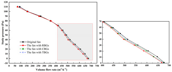
Figure 12.
Comparison of P–Q curve between original fan and those with bionic grooves.
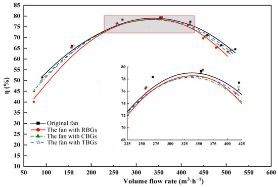
Figure 13.
Comparison of –Q curve between original fan and that with bionic groove.
Overall, the volume flow rate of the four fans decreased with the increase in outlet pressure, and the performance of the multi-blade centrifugal fan with bionic grooves were lower than the original fan under large flow rate conditions. Between them, the performance change of the multi-blade centrifugal fan with RBGs was the most, and the average attenuation rate of volume flow rate under all working conditions was 3.7%. When the bionic groove was circular or triangular, the fan performance was better than that of the fan with the rectangular groove. Under the small flow rate conditions, the fan performance with CBGs and TBGs was the same, but under medium flow rate conditions, the performance of the multi-blade centrifugal fan with TBGs was superior. A possible reason for this is that compared to circular and rectangular bionic grooves, triangular bionic grooves have more advantages in vortex breaking, which can weaken the vortex intensity at the axial clearance, so as to optimize the flow state at the blade tip.
As shown in Figure 13, the efficiency change trends of the multi-blade centrifugal fans with RBGs, CBGs and TBGs were the same as the original fan. According to the volume flow rate, under small flow rate and large flow rate conditions, the influence of the bionic grooves on the efficiency of multi-blade centrifugal fan was in the following order: RBG > CBG > TBG, i.e., the efficiency of the multi-blade centrifugal fan with TBGs was the highest between the fans with grooves. Under medium flow rate conditions, as shown in the enlarged diagram, the curvature of the high-efficiency area of the fan with RBGs changed more obviously, i.e., the high-efficiency area narrowed. In contrast, the curves of the high-efficiency areas of the multi-blade centrifugal fans with CBGs and TBGs were flat and the fluctuations in efficiency were small. The volume flow rate of these three fans with bionic grooves changed little. The cause of this reduction in efficiency is that the blade tip groove changes the pressure distribution of the blade, which affects the blade’s work ability. This effect is more obvious in the cases of small flow rate and large flow rate.
In conclusion, RBGs, CBGs and TBGs have an influence on the external characteristics of the multi-blade centrifugal fan, but the overall influence is small, which can be considered as unchanged, i.e., the blade tip bionic groove has little effect on the aerodynamic performance of the multi-blade centrifugal fan.
3.1.2. Internal Flow Characteristic
As shown in Figure 14, the internal flow field section of the multi-blade centrifugal fan was selected for analysis of the characteristics, and the influence of the bionic groove on the velocity distribution in the volute and flow state of the impeller was revealed. Figure 14a is the section A–A with rotation angle . Figure 14b shows axial sections with and and these two sections are defined as section and , respectively.
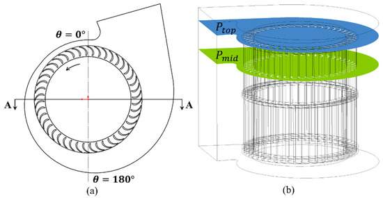
Figure 14.
Observation section: (a) the section A–A and (b) the section and .
As shown in Figure 15a, the velocity field in the volute was symmetrically distributed, and the velocity distribution of different fans was different at the impeller outlet and impeller tip. The impeller outlet flow velocity of the fan with TBGs was the highest. Compared to the original fan, by employing TBGs the impeller outlet flow velocity increased and the areas of the medium- and high-velocity regions also increased. The areas of the high-velocity regions of the multi-blade centrifugal fans with RBGs and CBGs decreased, but the areas of the medium-velocity regions increased. The velocity distributions at the impeller tips of the four fans are shown in Figure 15b. The uniformity was the best when employing TBGs. The RBGs made the uniformity of the velocity distribution the worst, which resulted in an increase in the area of the low-velocity region. The flow at the impeller tip was optimized and the bad flow state caused by the uneven velocity distribution was weakened by adopting CBGs and TBGs. Through the analysis of the internal flow in the volute, it was found that the flow velocity at the impeller outlet of the fan with TBGs was increased and its velocity distribution at the impeller tip was more uniform. Therefore, TBGs are better than CBGs and RBGs when applied to the multi-blade centrifugal fan.
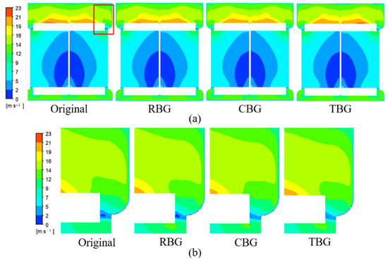
Figure 15.
Velocity distribution of section A–A: (a) volute and (b) impeller tip.
The research object is a double-suction multi-blade centrifugal fan. The impeller is symmetrical on both sides, so only one side section of impeller was taken for flow analysis. The streamline distributions of the and sections are shown in Figure 16. In the section , when rotation angle , there were vortices in the impeller passages caused by flow separation. In comparison to the original fan, the vortex intensity decreased when employing TBGs, which was manifested in the reduction in the shedding vortices on the suction surface and the reduction in the area of the low-velocity flow region in the passage; this is the reason for the increase in impeller outlet velocity when adopting TBGs. The vortex intensities of the multi-blade centrifugal fans with RBGs and CBGs increased. The increase in the shedding vortex on the suction surface caused blockage of the flow in the impeller passages. Additionally, the area of the low-velocity region increased, resulting in a decrease in the flow velocity at the impeller outlet. At the section , the fluid flow state is complex and changeable. Moreover, the degree of flow separation is serious. Many impeller passage vortices are generated, which are caused by blade tip leakage. It can be seen in Figure 16 that the vortices of the original fan, as well as the fans with RBGs, CBGs and TBGs were mainly distributed in and . Thus, the tip leakage was not reduced when using RBGs and CBGs. While the distribution range of leakage flow was not reduced when using TBGs, its scale was reduced and the effective flow area of the impeller was increased, so the performance of the multi-blade centrifugal fan with TBGs was improved.
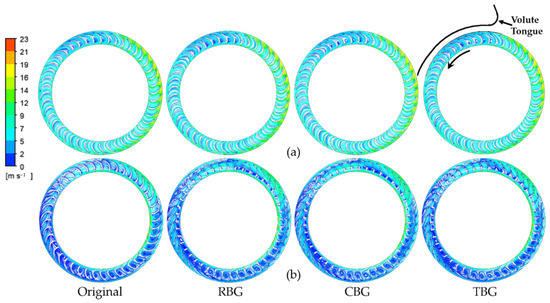
Figure 16.
Velocity streamline distributions in the impeller of multi-blade centrifugal fans with different blade tip groove shapes: (a) at the section and (b) at the section .
To summarize, triangular bionic grooves are better than rectangular and circular grooves. In other words, between RBGs, CBGs, and TBGs, TBGs perform the best in improving the aerodynamic performance of the multi-blade centrifugal fan. Compared to the original fan, the overall change trend of the velocity distribution in the volute and the vortex intensity in the impeller passages of the fan with bionic groove was smaller. Therefore, the influence of the bionic groove structure on the aerodynamic performance of the original fan can be basically ignored. In addition, according to the flow state of the section , it can be seen that the circumferential flow between the pressure surface and suction surface was formed because of the existence of the bionic groove, which affected the inlet state of the blade. The generation location of the circumferential flow is affected by the starting position of the bionic groove: if the starting position is too close to the leading edge of blade, a strong circumferential flow will be formed, resulting in a change of the inlet angle. Finally, this change prevents the air flow from entering the impeller and the flow state at the blade tip is worsened. Thus, the position of the bionic groove is set to start at the trailing edge of blade, rather than the leading edge of blade.
3.2. Noise Characteristics
3.2.1. Noise Characteristics
The noise results obtained by numerical simulation are shown in Table 3. Under the same volume flow rate, the noise of the fans with RBGs and CBGs was higher than that of the original fan, while the noise of the fan with TBGs was reduced by approximately 0.5 dB.
Table 3.
Results of Noise and Volume Flow Rate.
In order to reveal the noise distribution characteristics of the multi-blade centrifugal fan at different frequencies, the SPL spectrum of the fan obtained numerically is shown in Figure 17. The multi-blade centrifugal fan is a low-pressure fan, and its noise is mainly low-frequency noise. Therefore, the noise spectrum with frequency in the range of 0–2000 Hz was selected as the focus of analysis.
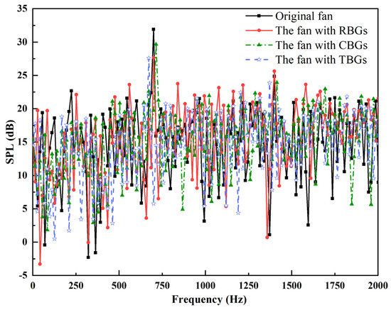
Figure 17.
Comparison of SPL spectrum between original fan and that with bionic groove.
As can be seen in Figure 17, the SPL distribution of the four fans have obvious discrete characteristics. The first peak of the original fan and the fans with RBGs, CBGs, and TBGs all appear at 700 Hz, which corresponds to the fundamental frequency of the blade passing frequency (BPF). The SPL value of the fan with TBGs is lower than that of the original fan across the whole frequency, and the decrease is more obvious when the frequency is the fundamental frequency and double the frequency of BPF. This is the reason that the aerodynamic noise of the multi-blade centrifugal fan with TBGs is effectively reduced. It is worth noting that the SPL values of the fan with RBGs and CBGs at BPF also decreased slightly, but the total noise did not decrease. It was found that the SPLs of the fans with RBGs and CBGs increase in other frequency bands except the fundamental frequency, and that SPL is increased more obviously when using RBGs. It can be understood that RBGs and CBGs disperse the noise of the fundamental frequency to nearby frequencies, resulting in no reduction in the total noise of both.
At present, of the methods of identifying vortex structure, the Q criterion is widely used and has good applicability [29]. The original fan and the fan with TBGs were selected for comparison, and the Q criterion was used to visually display the vortex structure, so that the influence of triangular bionic groove on the vortex intensity could be observed. The Q criterion vorticity distributions of the original fan and that with TBGs are shown in Figure 18. The effect of TBGs in reducing the intensity of the shedding vortex existed mainly in the range of , and the acting object can be divided into the tip vortex and the impeller passage vortex. When , the tip vortex and impeller passage vortex were significantly weakened by employing TBGs. When , the role of TBGs was mainly reflected in the impeller passage vortex, and the effect was obvious when was in the range of 210~270°. The performance specifics were that the tip vortex had no obvious change at , while the impeller passage vortex basically disappeared () or its scale decreased ().
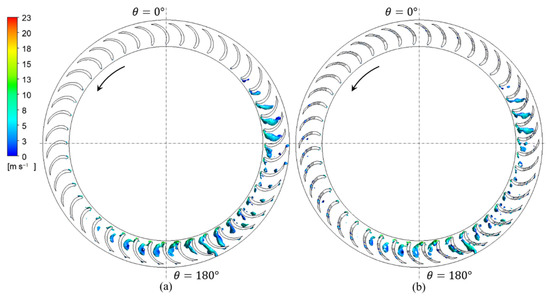
Figure 18.
Vorticity distributions in the impellers (a) Original fan; (b) The fan with TBG.
In order to study the noise reduction characteristics of the blade tip bionic groove, 12 noise monitoring points were evenly arranged every 30 degrees along the circumference of the section , as shown in Figure 19. Figure 20 shows the results of aerodynamic noise at the monitoring points of the original fan and the multi-blade centrifugal fan with TBGs. The noise of the multi-blade centrifugal fan with TBGs was reduced at all monitoring points, especially when the rotation angle equaled , where the reduction in aerodynamic noise reached its maximum. The main component of noise in this range is vortex noise, and a reduction in vortex intensity leads to noise reduction. In this range, the degree of flow separation at the impeller tip was effectively reduced by TBGs, and hence the vortex noise was also reduced. When , the SPL reduction at the volute tongue was less than that at other monitoring points. The dynamic and static interaction between the impeller and the volute tongue is the main causative agent of noise at the volute tongue. However, TBGs mainly contributed to reducing the leakage flow at the impeller tip, thus reducing the vortex noise of the impeller; therefore, the SPL reduction at the volute tongue was small. Through the above analysis, the aerodynamic noise generated by the fan with TBGs was lower than that of the original fan. Thus, it is feasible to reduce the noise of multi-blade centrifugal fans by using triangular blade tip bionic grooves.
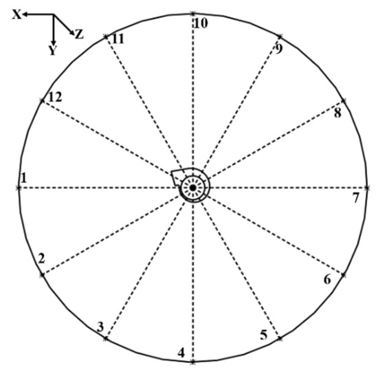
Figure 19.
Noise monitoring points.
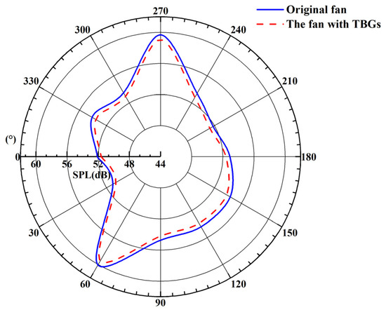
Figure 20.
Noise results of original fan and the fan with TBGs.
3.2.2. Noise Reduction Mechanism
Although the influence of blade tip bionic grooves on the aerodynamic performance and noise characteristics of multi-blade centrifugal fan has been described above, the physical mechanism of noise reduction has not been explained. This section will explain the physical mechanism of noise reduction from three aspects: (1) The sound pressure level spectrum of the multi-blade centrifugal fan with TBGs and that of the original fan, as shown in Figure 17. The SPL at BPF contributes more when evaluating the noise reduction. By employing TBGs, the SPL was 13.5% lower than that of the original fan at 700 Hz and 4% lower at 1400 Hz, and the SPL of other frequency bands was also lower than that of the original fan. As such, the noise value of the multi-blade centrifugal fan with TBGs was smaller than that of the original fan. (2) The noise sources of centrifugal fan, including vortex noise caused by the blade separation vortex shedding, the secondary flow, and the flow at the collector clearance. According to the source term of the dipole in the FW-H equation, reducing the vortex shedding at the trailing edge of the blade or reducing the pressure fluctuation are conducive to reducing noise. If the curl of the fluid flow can be reduced, the vorticity in the process of fluid flow then can be reduced, so as to reduce the noise. As shown in Figure 18, the vorticity of the multi-blade centrifugal fan with TBGs was significantly less than that of the original fan. According to Powell’s vorticity equation, the reduction in vorticity is conducive to reducing the fan noise. (3) The noise of the fan is related to the propagation characteristics of the noise source. As shown in Figure 20, on the axial cross section the aerodynamic noise was reduced at all monitoring points by adopting TBGs. The propagation of SPL decreased significantly in the rotation angles from 150° to 270°. Several factors work together to reduce the noise of multi-blade centrifugal fans.
4. Conclusions
The multi-blade centrifugal fan was taken as the research object in the presented research. Through the introduction of bionic grooves to the impeller blade tip, the effects of the basic structural parameters of the grooves and different groove shapes on the aerodynamic performance and noise characteristics of the multi-blade centrifugal fan were studied numerically. The main conclusions obtained are as follows:
(1) When the basic parameters of the blade tip bionic grooves change, the aerodynamic performance of the multi-blade centrifugal fan remains basically unchanged.
(2) Compared with the original fan, the flow velocity at the impeller outlet of the multi-blade centrifugal fan with triangular bionic grooves increases, and the velocity distribution at the impeller tip is more uniform. The degree of flow separation on the blade suction surface is also weakened because of the groove structure, so the shedding vortex on the suction surface is reduced.
(3) Under the same volume flow rate, the noise value of the multi-blade centrifugal fan with triangular bionic groove is 0.5 dB lower than that of the original fan. The sound pressure level of the multi-blade centrifugal fan with triangular bionic grooves in the whole frequency band is lower than that of the original fan, and it is significantly reduced when the frequency is either the fundamental frequency or double the frequency of the blade passing frequency.
(4) The intensity of the tip vortex, which is distributed in the blade inlet, and the shedding vortex in the impeller passages is effectively weakened by the triangular bionic groove. Thus, the vorticity in the process of fluid flow and the vortex noise of the multi-blade centrifugal fan are reduced. By introducing reasonable blade tip bionic grooves, the total sound pressure level of the multi-blade centrifugal fan is reduced. This shows that it is feasible to reduce the noise of multi-blade centrifugal fans by using triangular blade tip bionic grooves.
Author Contributions
Conceptualization, Z.X., Y.L. and G.X.; data curation, Z.X.; formal analysis, Z.X.; investigation, Z.X., Y.L. and W.Q.; methodology, Z.X. and Y.L.; project administration, W.Q.; resources, Z.X., X.L., W.Q. and G.X.; software, Z.X.; supervision, X.L.; validation, Z.X. and Y.L.; visualization, Z.X. and Y.L.; writing—original draft, Z.X. and Y.L.; writing—review and editing, Z.X. and X.L. All authors have read and agreed to the published version of the manuscript.
Funding
This research was funded by the National Natural Science Foundation of China, grant number No. 51676152.
Institutional Review Board Statement
Not applicable.
Informed Consent Statement
Not applicable.
Conflicts of Interest
The authors declare no conflict of interest.
References
- Neise, W. Noise reduction in centrifugal fans: A literature survey. J. Sound Vib. 1976, 45, 375–403. [Google Scholar] [CrossRef]
- Gad-el-Hak, M. Modern developments in flow control. Appl. Mech. Rev. 1996, 49, 365–379. [Google Scholar] [CrossRef]
- Yousefi, K.; Saleh, R. Three-dimensional suction flow control and suction jet length optimization of NACA 0012 wing. Meccanica 2015, 50, 1481–1494. [Google Scholar] [CrossRef]
- Yousefi, K.; Saleh, R. The effects of trailing edge blowing on aerodynamic characteristics of the NACA 0012 airfoil and optimization of the blowing slot geometry. J. Theor. Appl. Mech. 2014, 52, 165–179. [Google Scholar]
- Zhang, Z.Y.; Zhang, W.L.; Chen, Z.; Sun, X.H.; Xia, C.C. Suction control of flow separation of a low-aspect-ratio wing at low Reynolds-number. Fluid Dyn. Res. 2018, 50, 065504. [Google Scholar]
- Singhal, A.; Castañeda, D.; Webb, N.; Samimy, M. Control of Dynamic Stall over a NACA 0015 Airfoil Using Plasma Actuators. AIAA J. 2017, 56, 78–89. [Google Scholar] [CrossRef]
- McAuliffe, B.R.; Yaras, M.I. Passive manipulation of separation-bubble transition using surface modifications. J. Fluids Eng. 2009, 131, 021201. [Google Scholar] [CrossRef]
- Seo, S.H.; Hong, C.H. Performance improvement of airfoils for wind blade with the groove. Int. J. Green Energy 2016, 13, 34–39. [Google Scholar] [CrossRef]
- Raayai-Ardakani, S.; McKinley, G.H. Drag reduction using wrinkled surfaces in high Reynolds number laminar boundary layer flows. Phys. Fluids 2017, 29, 093605. [Google Scholar] [CrossRef]
- Raayai-Ardakani, S.; McKinley, G.H. Geometric optimization of riblet-textured surfaces for drag reduction in laminar boundary layer flows. Phys. Fluids 2019, 31, 053601. [Google Scholar] [CrossRef] [Green Version]
- Qiao, W.Y.; Tong, F.; Chen, W.J.; Wang, X.N.; Chen, Z.W. Review on aerodynamic noise reduction with bionic configuration. Acta Aerodyn. Sin. 2018, 36, 98–121. [Google Scholar]
- Zhu, H.; Hao, W.; Li, C.; Ding, Q.; Wu, B. A critical study on passive flow control techniques for straight-bladed vertical axis wind turbine. Energy 2018, 165, 12–25. [Google Scholar] [CrossRef]
- Shukla, V.; Kaviti, A.K. Performance evaluation of profile modifications on straight-bladed vertical axis wind turbine by energy and Spalart Allmaras models. Energy 2017, 126, 766–795. [Google Scholar] [CrossRef]
- Robarge, T.; Stark, A.; Min, S.K.; Khalatov, A.; Byerley, A. Design considerations for using indented surface treatments to control boundary layer separation. In Proceedings of the 42nd AIAA Aerospace Sciences Meeting and Exhibit, Reno, NV, USA, 5–8 January 2004; p. 425. [Google Scholar]
- Dai, C.; Ge, Z.P.; Dong, L.; Liu, H.L. Research on characteristics of drag reduction and noise reduction on V-groove surface of bionic blade of centrifugal pump. J. Huazhong Univ. Sci. Technol. (Nat. Sci. Ed.) 2020, 48, 113–118. [Google Scholar]
- Ye, X.M.; Li, P.M.; Li, C.X.; Ding, X.L. Numerical investigation of blade tip grooving effect on performance and dynamics of an axial flow fan. Energy 2015, 82, 556–569. [Google Scholar] [CrossRef]
- Kharati-Koopaee, M.; Moallemi, H. Effect of blade tip grooving on the performance of an axial fan at different tip clearances in the absence and presence of inlet guide vanes. Proc. Inst. Mech. Eng. A—J. Power Energy 2020, 234, 72–84. [Google Scholar] [CrossRef]
- Kodama, K.; Saydur Rahman, M.; Horiguchi, T.; Thomas, P. Assessment of hypoxia-inducible factor-1α mRNA expression in mantis shrimp as a biomarker of environmental hypoxia exposure. Biol. Lett. 2012, 8, 278–281. [Google Scholar] [CrossRef] [Green Version]
- Huang, C.; Li, D.J. The performance analysis and optimal design of multi-blade centrifugal fan with fluent. In Proceedings of the 2014 International Conference on Information Science, Electronics and Electrical Engineering, Sapporo, Japan, 26–28 April 2014. [Google Scholar]
- Yu, L.; Song, W.P.; Yan, L. An effective method for predicting aerodynamic noise for wind turbine flatback airfoils. J. Northwestern Polytech. Univ. 2012, 30, 513–517. [Google Scholar]
- Han, Z.H.; Song, W.P.; Qiao, Z.D. Aeroacoustic calculation for helicopter rotor in hover and in forward flight based on FW-H equation. Acta Aeronaut. Astronaut. Sin. 2003, 24, 400–404. [Google Scholar]
- Son, P.N.; Kim, J.W.; Byun, S.M.; Ahn, E.Y. Effects of inlet radius and bell mouth radius on flow rate and sound quality of centrifugal blower. J. Mech. Sci. Technol. 2012, 26, 1531–1538. [Google Scholar] [CrossRef]
- Carmichael, B. Low Reynolds Number Airfoil Survey; no. NASA CR-165803; National Aeronautics and Space Administration, Langley Research Center: Hampton, VA, USA, 1981. [Google Scholar]
- Wu, Y.L.; Chen, Q.G.; Liu, S.H. Fans and Compressors, 2nd ed.; Tsinghua University Press: Beijing, China, 2011; pp. 222–233. [Google Scholar]
- Wang, K.; Ju, Y.P.; Zhang, C.H. Design of multi-blade centrifugal fan based on grouping model and bionic volute tongue. J. Eng. Thermophys. 2017, 38, 1671–1675. [Google Scholar]
- Green, P.A.; Patek, S.N. Contests with deadly weapons: Telson sparring in mantis shrimp (Stomatopoda). Biol. Lett. 2015, 11, 20150558. [Google Scholar] [CrossRef] [PubMed] [Green Version]
- Rosario, M.V.; Patek, S.N. Multilevel analysis of elastic morphology: The mantis shrimp’s spring. J. Morphol. 2015, 276, 1123–1135. [Google Scholar] [CrossRef] [PubMed]
- Tian, C.Y.; Wu, L.M.; Liu, X.M.; Huang, Y.T.; Ma, L.; Li, J.B. Study on aerodynamic noise reduction of multi-blades centrifugal fan by using blades with grooved inlet end. Chin. J. Turbomach. 2020, 62, 58–64. [Google Scholar]
- Zhang, Y.N.; Liu, K.H.; Xian, H.Z.; Du, X.Z. A review of methods for vortex identification in hydroturbines. Renew. Sust. Energy Rev. 2018, 81, 1269–1285. [Google Scholar] [CrossRef]
Publisher’s Note: MDPI stays neutral with regard to jurisdictional claims in published maps and institutional affiliations. |
© 2022 by the authors. Licensee MDPI, Basel, Switzerland. This article is an open access article distributed under the terms and conditions of the Creative Commons Attribution (CC BY) license (https://creativecommons.org/licenses/by/4.0/).