Article

Application of Paraffin-Based Phase Change Materials for the Amelioration of Thermal Energy Storage in Hydronic Systems

by
Dua’a S. Malkawi
1,*,
Rabi Ibrahim Rabady
2,
Mosa’b S. Malkawi
3 and
Said Jereis Al Rabadi
4
1
Engineering Department, Al-Balqa Applied University, P.O. Box 7041, Al-Salt 19117, Jordan
2
Electrical Engineering Department, Jordan University of Science and Technology, P.O. Box 3030, Irbid 22110, Jordan
3
Mechanical Engineering Department, Jordan University of Science and Technology, P.O. Box 3030, Irbid 22110, Jordan
4
Chemical Engineering Department, Al-Balqa Applied University, P.O. Box 50, Al-Huson 21510, Jordan
*
Author to whom correspondence should be addressed.
Energies 2023, 16(1), 126; https://doi.org/10.3390/en16010126
Submission received: 4 December 2022 / Revised: 16 December 2022 / Accepted: 19 December 2022 / Published: 22 December 2022
(This article belongs to the Topic Advances in Renewable Energy and Energy Storage)

Abstract

:
This study aims at investigating the improvement in the thermal performance of energy storage for a hydronic system when it is equipped with evacuated tubes integrated within a hot water tank. The PCM shell in the bottom section is thicker than at the top to maintain a uniform, minimal water temperature difference of 5 °C between the top and bottom sections of the hot water tank. The thermal performance of the system was analyzed in diverse months when the ambient temperature fluctuated. The results have revealed that the thermal performance in December, March, and June was 80%, 81%, and 84%, respectively, meaning that the thermal performance is optimal in warm weather. The results confirmed that the system had boosted the presence of hot water throughout the whole day, including the time of the sun’s absence, due to the release of stored PCM latent heat. The designed system solves the overheating problem and expands the availability of hot water through the cold weather. The system is characterized by lower heat losses because the average water temperature has decreased.

1. Introduction

Intensive combustion processes of conventional petroleum-based fuels pose a significant impact on the environment in the long term and in the vicinity of residential areas due to exposure to harmful concentrations of gaseous emissions, namely COx, SOx, and NOx. As a result, stringent environmental regulations against these gaseous emissions and the operability of thermal combustion facilities to reduce environmental impacts are legitimized [1]. Due to the rising costs of petroleum end-products and increased demands in thermal applications by the residential and industrial sectors, researchers have been encouraged to investigate new resources of renewable energies (REs) and develop eco-environmentally friendly REs such as photovoltaics (PVs) and thermal solar panels (SPs). The installation of solar panels on wide terrain is intended to collect solar energy during the day. Moreover, the current thermal energy demands strongly encourage researchers to explore promising engineering solutions for effective thermal energy depots and dispatching solutions. Thermal energy storage has become increasingly crucial, owing to its interaction with variable production resources, the increase in the demand for conventional fuels for the combustion process, and the adverse environmental impact of other RE sources. Therefore, the ideal way to balance thermal energy is for it to be stored in conservative depots utilizing phase change materials such as paraffin based PCMs, which are ecologically and economically ideal.
Thermal energy storage is a feasible compensation for fluctuations between production and consumption rates during peak demand periods through thermal energy depot facilities that could be integrated within RE producers’ and consumers’ buildups. The integration of PCMs with an energy storage system has several potential applications, including the intensive and cumulative latent heat of phase changes. Furthermore, the phase change process is compatible and better monitored, since it occurs ideally at isothermal temperatures [2]. Despite these REs’ potential, they possess a few deficiencies, such as crisp efficiency and less availability than other RE sources such as wind, traditional solar, and substrates for biofuel production [3]. The availability of sunlight varies across continents and between the earth’s upper and lower hemispheres, potentially influencing energy availability.
The PCM products can be classified into three categories: eutectic, organic, and inorganic materials [4,5,6,7,8,9]. Organic PCMs include paraffin and non-paraffin. The main advantages of organic materials are changing their phase without segregation and latent heat degradation; self-nucleation; non-corrosiveness; chemical stability and safety. Inorganic PCMs include salts, hydrates, and metallic materials. They have a high storage density, high thermal conductivity, are non-flammable, and are readily available, but they need a nucleation agent and have a super-cooling problem in the phase transition. Eutectics are mixtures of two or more components [4,5,6,7,8,9].
Hydronic systems are usually associated with liquid water as a heat transfer medium for the cooling and heating processes. A hydronic system typically includes both cooled and heated water cycles to allow for separate heat transfer. Typical temperature differences of such systems are within the range of 0 and 15 °C for cooling and between 20 and 100 °C for heating [10,11,12]. Recently, solar water collectors have been considered a significant alternative to traditional electric heaters in meeting domestic hot water requirements. Although solar water heaters are composed of various types, passive or natural convection types are used widely due to their simplicity and operational efficiency [13,14].
The development of traditional solar heating and cooling systems was reviewed in Ge et al., 2018; storing excess heat for further applications was recommended, and enhancements to the solar energy storage system were highlighted [15]. Moreover, Buker et al., 2015 discussed improvements in solar panel design, such as panel surface, tilt, and shading, that could have a significant influence on the performance of the integrated hydronic systems [16]. Nevertheless, the obstacle that limits the solar water collectors is the scarcity of matching demand and supply throughout the day. The operation of solar water collectors depends on the availability of the sun [17] and heat losses [18].
Several researchers have confirmed that thermal energy storage is an essential issue by using appropriate thermal storage material within the solar energy system, which could be incorporated in a storage tank [19,20,21] or with collector tubes [22,23]. Recently, the heat that is absorbed or released during a phase change of PCMs has been employed as a thermal storage battery, due to its higher latent heat, wide operating temperatures, and very good thermal properties [24,25,26,27,28,29,30,31]. A PCM absorbs and stores thermal energy during the sunny hours of the day; later, it releases the stored energy after the sun’s absence, which improves the solar system’s efficiency. Organic PCMs, such as paraffin wax, are best known for storing a large amount of energy due to their high latent heat, thermal and chemical durability, little sub-cooling, and non-toxicity [32,33]. In the recent literature, the thermal behavior of paraffin-based PCMs was studied for the energy depot process. Murali et al., 2015 have examined the effectiveness of flat-plate solar water collectors incorporating paraffin as a PCM in a container placed in the top section of the water tank. Their findings appear to improve the performance of the solar system [34]. Kumar et al., 2020 have investigated the behavior and effect of applying synthesized nano-PCMs on the energy storage of evacuated solar water heating systems. According to their findings, PCMs were filled in evacuated solar tubes, which were connected to cylindrical containers placed inside the water tank [21], and such PCMs flowed as liquid inside and served as an energy storage medium to heat the water inside the main tank. In a previous study, we investigated the thermo-physical properties of PCMs by studying the enhancement of the thermal conductivity of the heat transfer medium of a PCM with the addition of carbon nanotubes (CNT) and graphite nanoparticles (GNP) as nanofillers to PCM composites [35]. So, future outcomes will focus on the enhancement of the performance efficiency of the solar system by adding nanoparticles to the PCM, which are then incorporated into the system. In this context, prior studies [36,37,38] have addressed the application of a shell and tube thermal storage heat exchanger equipped with finned outer walls for the tubes, and the enthalpy-porosity method was utilized to reveal the transient behavior of the PCMs’ melting process. This approach could be subject to various complexities, and several criteria must be met to apply the proposed enthalpy-porosity method. In addition, the wavy annulus tubes could cause apparent vortices inside the heat exchanger that affect the natural convection of heat transfer.
Generally, the reviewed studies imply that the integration of PCMs within a solar system could ameliorate the performance of the thermal mass, maximize operational simplicity, and recover the thermal energy of the hydronic solar system for off-peak periods. It could be understood that few attempts were made to establish an in-field hydronic system that has a potential application of heating water in residential and industrial premises and to replace conventional electrical/fuel-based water heating systems, thereby improving energy storage efficiency during off-peak periods and reducing relevant energy expenses in premises. This study may offer guidance for future research and the thermal design of domestic hydronic solar systems. The performance of the system is assessed with an integrated PCM that is distributed on the shell side of the water storage tank, such that the PCM shell has a different thickness at the top and bottom of the storage tank (the bottom portion is thicker than the top). The effect of the PCM in a natural circulation solar water collector was examined through normal domestic hot water consumption, complete and sudden emptying of the hot water storage tank, and no hot water consumption.

2. Methodology

2.1. Experimental Setup

The manufactured hydronic solar system is located on the Jordan University of Science and Technology campus. Its geographic coordinates are 32.49° N (latitude) and 35.99° E (longitude). The solar collector that was used is an evacuated tube setup with an inclined angle of 45°. The inclined angle was chosen after making calculations to obtain higher gains in energy in the winter and solve the overheating problem in the summer. The main features of the evacuated tube of the solar collector are presented in Table 1.
In addition to evacuated tubes, the system contains a water storage tank with a total capacity of 0.200 m3, a length of 1.6 m, and a diameter of 0.45 m. It is made of galvanized steel with an outer shell with a diameter of 0.53 m and contains paraffin wax as PCM with a thickness of 2 cm at the top and 4 cm in the bottom portion; such an asymmetric design is believed to assist in charging and discharging heat into the system since it provides more effective buoyancy motion for the liquid PCM. The tank was thermally insulated by rock wool to reduce the loss of energy. The insulation shell is covered with galvanized steel sheet. All specifications of the storage tank are shown in Figure 1.
The phase change material that was used in this system was paraffin wax with a melting temperature of 48 °C. It was chosen due to its thermal stability, low price, no sub-cooling problem, and suitable latent heat. The thermal specifications of paraffin wax are presented in Table 2.
Additionally, the system consists of a solenoid valve that is programmed to meet the level of family consumption of hot water throughout the day. This valve withdraws hot water at specific times; the following diagram shows the proposed water consumption pattern, which presents the distribution of hot water throughout the day. Figure 2 shows a daily water consumption pattern according to real observed consumption and required estimations.
The system contains a cold water tank to recover hot water discharged from the hot water tank. Thermocouples (Type K) were fixed through the storage tank to notice and record water and PCM temperatures during the heating process. Thermocouples were installed in the system to detect the temperatures of the water, PCM, and ambient. They were placed in the water region in three positions: two at the top and one at the bottom. Additionally, other thermocouples were placed in three positions throughout the PCM region: two at the top and one at the bottom. One thermocouple reads the ambient temperature. All thermocouples were connected to a converter that gives temperature readings in Celsius. The data logger was connected to read and record the temperatures with Windows software easily plugged into a computer. For measuring irradiance (w/m2), a pyranometer was used. The data was acquired and stored every 4 min. An additional experiment was performed every 5 s and the reading was recorded. The hot water tank was discharged completely in the evening (specifically at sunset) to investigate the water and PCM temperature behavior in this case.
As for the hot water region, the PCM region was also equipped with two holes and a lid to fill and discharge the PCM at any time based on necessity. Moreover, the problem of high pressure throughout the system is resolved by setting up vents for both the water and the PCM regions. A photographic view and schematic diagram of the system are presented in Figure 3. The water is replenished from the water supply tank. The hot water storage cylinder receives hot water passively from the evacuated tube, whereas the hot water flows up to the tank naturally due to thermosiphon circulation. The hot water was then used for domestic use, and hot water consumption was recovered by the water supply tank. When water gains heat from solar energy, it conductively exchanges this energy with the PCM. Conversely, as the temperature of water decreases, the latent heat will be released to the water from the PCM during the liquid phase until solidification in the absence of the sun.

2.2. Thermal Model

Energy balance is applied to both parts of the hydronic solar system under steady-state conditions: the evacuated tube and hot water storage tank. The useful energy gained from solar radiation by evacuated tubes can be expressed by [40,41]:
Q u s e f u l = I   A c   τ α e f f   k θ i Q l o s s
and
Q l o s s ,   t u b e = U L , t u b e   A c   T w T a ,
where I represents a global solar irradiance, Ac represents a solar collector area, (τα)eff represents an effective transmissivity-absorptivity product coefficient, kθi represents an incident angle modifier, U L , t u b e . represents an over-all heat transfer coefficient of heat loss from the evacuated tubes, and T w   and   T a . represent water and ambient temperatures, respectively.
The solar collector’s efficiency ɳ . is determined by the value of the ratio between useful energy and solar radiation that falls on the collector. This can be expressed by:
ɳ = Q u s e f u l I   A c
Solar collector efficiency (evacuated tubes) can be explained by:
ɳ c o l l e c t o r = τ α e f f   k θ i U L , t u b e   T w T a I
The following equation clarifies how the useful energy leaving the evacuated tubes moves to the water tank, which transfers to paraffin, giving rise to temperature changes:
Q P C M = m P C M   c p ,   P C M   Δ T s o l i d + m P C M   λ P C M + m P C M   c p ,   P C M   Δ T l i q u i d
Energy balance in the water tank can be expressed by:
E a c c u m u l a t i o n = Q u s e f u l ± Q P C M Q l o a d Q l o s s , t a n k
Useful energy, load energy, and the heat loss of the water tank can be calculated by:
Q u s e f u l = m w ,   t a n k   · c p ,   w   · T o u t ,   w T i n ,   w
Q l o a d = m w , l o a d   · c p ,   w   · T w T a
Q l o s s ,   t a n k = U L ,   t a n k   A t a n k   T w T a
The overall heat transfer coefficient of energy losses in the system (UL,sys) is equivalent to the losses of both the evacuated tube and the water tank. This can be expressed by:
U L , s y s = U L , t u b e + U L ,   t a n k
The efficiency of the system with paraffin as the PCM is:
ɳ s y s t e m = ɳ c o l l e c t o r   ·   ɳ P C M
ɳ s y s t e m = τ α e f f   k θ i U L , s y s   T H 2 O T a I ·   Q P C M I   A c
The domestic hydronic solar system was evaluated according to EN 12976 standards, where the solar radiation, water temperature, ambient, and PCM temperatures were recorded for more than 9 months consecutively under two test types: with PCMs and without PCMs. According to ISO 9459-5 DST, the withdrawals of hot water from the storage tank depended on family consumption patterns throughout the testing period. Thermal output characterization tests were conducted according to the results of calculating instantaneous system performance experimentally and theoretically and calculating water storage tank heat losses. The hydronic solar system’s thermal performance was measured on days with daily solar radiation and temperatures recorded over consecutive months at different water storage inlet temperatures. Protection against overheating and pressure resistance standards were considered necessary to save the system from deformation.

3. Results and Discussion

The average values of the solar radiation at the JUST campus throughout the year are shown in Figure 4. The temperature distributions of the ambient, water, and PCM at the storage tank were recorded during system testing. All parameters of the system were studied for many months over a year to investigate the effect under different weather conditions.

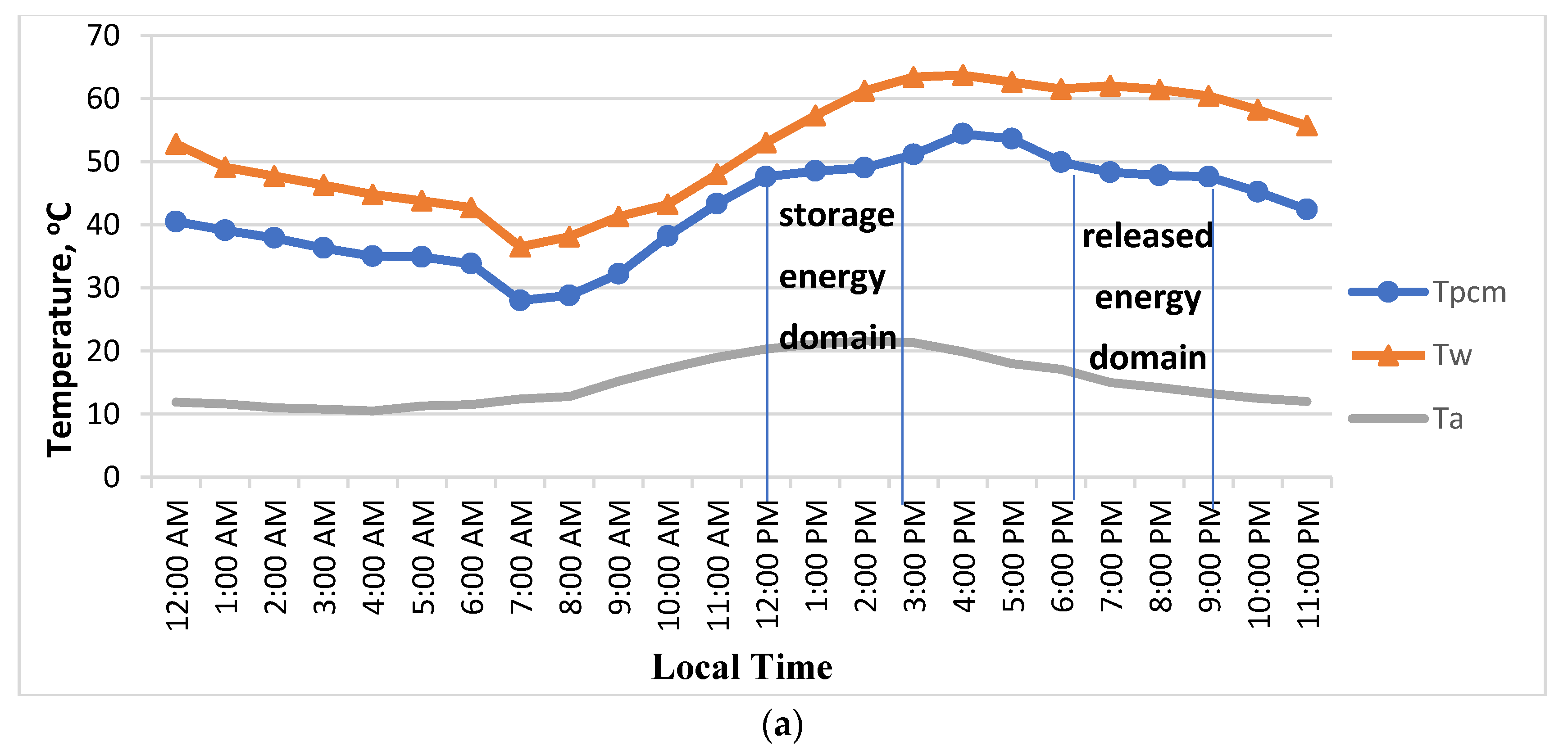
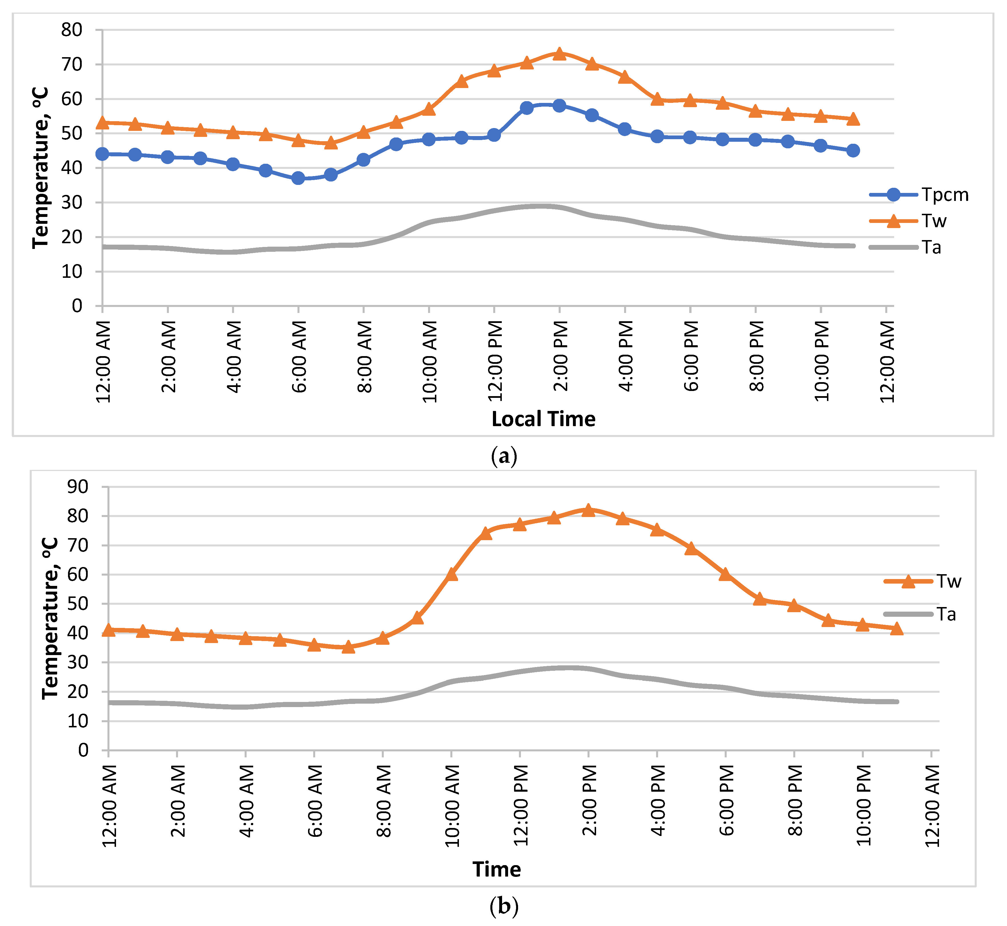
3.1. Temperature Distributions

The temperature distributions of the ambient, PCM, and water at the storage tank (average) with and without PCMs are shown in Figure 5, Figure 6 and Figure 7. In these figures, it is noticeable that the water temperature increases from sunrise until it reaches the melting temperature of paraffin. The water temperature remains at a fixed value until the paraffin melts completely, at which point it increases to a specific value. The temperatures decrease with the decrease in energy gained from the sun at the end of the day. While the water temperature rises through circulation in the evacuated tubes, water flows into a storage tank where thermal energy exchange starts between hot water and paraffin, which further raises the paraffin’s temperature. So, the temperature of the paraffin at the beginning of the day increases gradually with the increasing water temperature that comes from the evacuated tubes. When paraffin reaches its melting point, the temperature stays constant, increases to the maximum specified value, and then gradually decreases at night as a result of the absence of energy from solar radiation. At the melting and solidification temperature of the PCM, the water temperature stays at a fixed value, which can be observed in Figure 5, Figure 6 and Figure 7.
The following can be observed by using a PCM case: when the PCM temperature reaches its melting point throughout the day, the stored energy begins the PCM phase change from a solid to a liquid. This stored energy is used as released energy in water to maintain its temperature within the domestic usage range.
The temperatures of paraffin decrease constantly in the afternoon to reach a solidification point and stay at the same temperature for a short period, with an exchange of latent heat that is released in water. This process is reflected in the values of water temperatures, where the decrease is very small. Energy loss during the late afternoon and night hours is higher than at any other time during the day. The water temperatures are in the range for domestic use, which is the main goal of the system. The thermal energy that transfers between water and paraffin depends on the temperature difference between them and on the phase of paraffin (liquid or solid). Throughout the day, with the presence of solar energy, the glazing temperature, energy collected, and water temperature increase. Approximately at solar noon, water temperatures reach their maximum.
It can be observed in Figure 5, Figure 6 and Figure 7 that water temperatures at solar noon without using a PCM case are higher than those with PCMs. Higher values due to the transfer of energy from water to PCMs mean a reduction in overheating problems in the water tank. Conversely, through early morning and late afternoon, the water temperatures are lower than those reached when using paraffin as a PCM.
Figure 8 shows different temperature distributions, and the experiment of discharging the storage tank of hot water completely was performed. This experiment was conducted to study the behavior of the PCM and heat exchange with water by discharging all amounts of hot water in the water tank at 4:00 PM. The withdrawal of hot water is replaced by cold water. It is evident from Figure 8 that the water temperature decreases sharply through the discharge process, along with the PCM temperature. After that, the water temperature begins to rise as a result of the heat exchange from the PCM.
The water and PCM reach the same temperature at a specific point in time. Additionally, the temperature of the water in the domestic use range can be considered optimal. This experiment shows the exchange of stored thermal energy in PCMs with water and its effect on water temperature. This experiment explains the family’s sudden and complete drain of the hot water from the water storage tank and how the PCM raises the water temperature by 10 °C over a short period of time.
Furthermore, Figure 9 shows the temperature distributions of hot water, PCM, and ambient temperature in the absence of hot water consumption throughout the day. This experiment was performed in approximately similar weather conditions to the previous one. It can be noticed that higher values of hot water and PCM temperatures are due to the absence of load energy. Moreover, it is clear that the temperature difference between water and paraffin is small; this difference is less than 1 °C in the morning hours with increasing gains in energy.
Due to the design of the storage tank, the thickness of the PCM layer on the top and bottom of the tank was different. The thickness at the bottom is higher than the top, which means more mass of PCM and more stored energy through the sun’s presence. This stored energy is released in the water at the bottom of the tank, which has a lower temperature than that in the top region. Releasing energy from PCMs means heating water, which makes the water through the whole tank have similar or small differences in temperature, especially in the late afternoon hours. Figure 10 presents the temperature distribution of water on the top and bottom regions; as can be seen, the maximum difference is approximately 5 °C during the daybreak hours. It can be observed that the water temperatures at the top and bottom of the tank are the same at solar noon. This study shows a decrease in water temperature compared with a hydronic solar system without a PCM, which is an advantage to reducing heat losses from the system and avoiding superheating through the tank. Furthermore, Azimi et al., 2015 found that the water temperature at the bottom of the tank is close to ambient temperature without PCMs [42].
Figure 10 presents a comparison and disparity between our study and that of Azimi et al. Not only do our results demonstrate a decrease in the difference between hot water and temperature at the top and bottom of the storage tank greater than that of Azimi et al., but they also show a decrease in the hot water in the system (within domestic use), which means less thermal energy losses and covers the hours of solar absence.

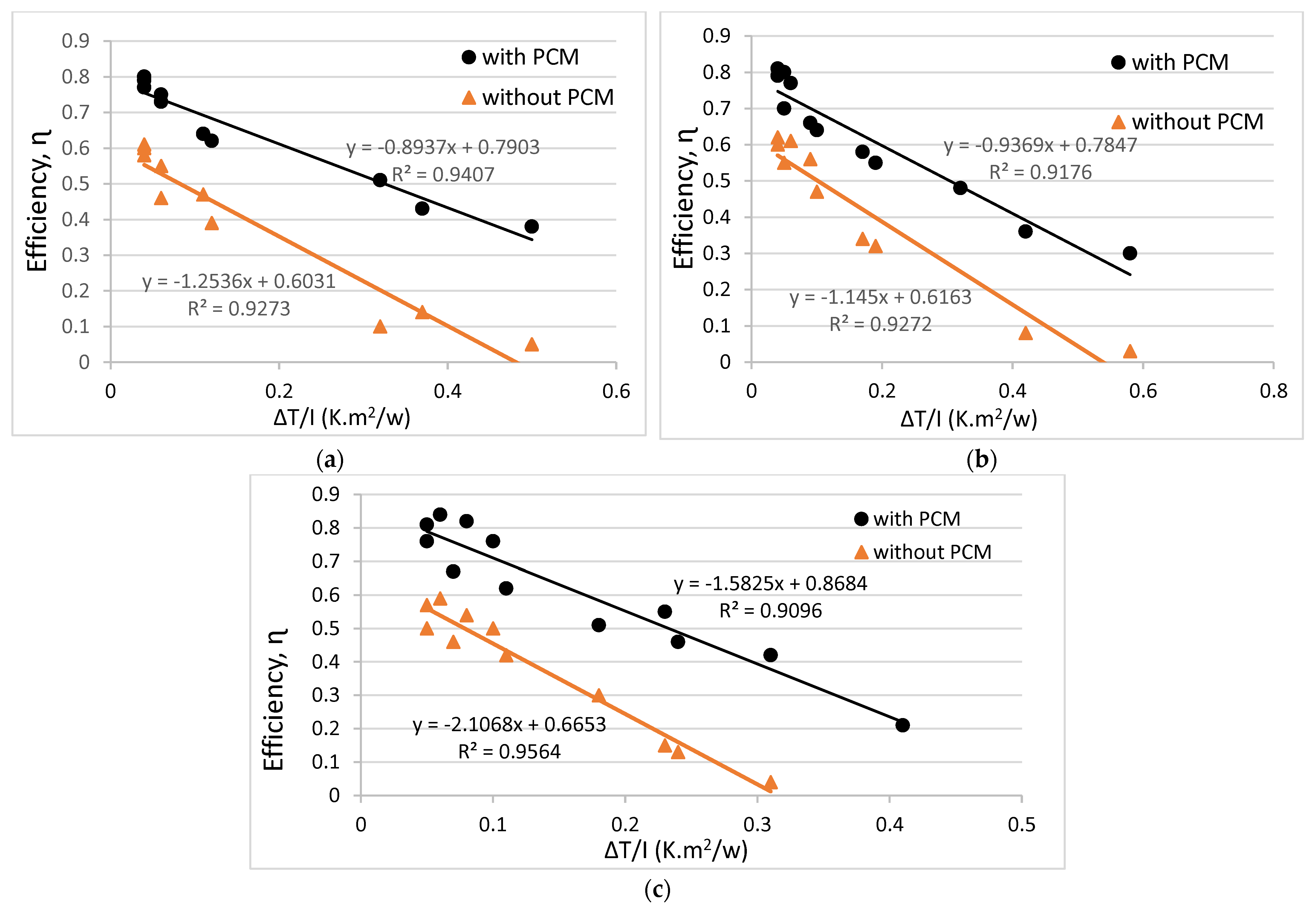
3.2. System Efficiency

The results of our experiments and theoretical calculations are summarized in Table 3, Table 4 and Table 5. The results show useful gains and losses in energy with the water temperature in the water storage tank for the clear days of December, March, and June. The lowest rate of useful energy is in the evening and morning. However, the highest value of useful energy at solar noon is due to the increasing gain in solar energy. Due to the greater temperature difference between the water and the ambient, heat loss is greater at noon than in the morning and evening. The experimental efficiency of the hydronic solar system was estimated by ( Q u s e f u l I   A c ). It is clear from the tables that the system efficiency rises progressively from sunrise to solar noon, the maximum value, then falls off. The maximum experimental efficiency is around 80% in December, 81% in March, and 84% in June. The instantaneous efficiency of the system without using PCMs is around 60%. So, the positive effect of using PCMs on the performance of the hydronic solar system is clear.
Figure 11 illustrates the relationship between the system’s thermal efficiency ( ɳ s y s t e m ) and the temperature difference between hot water and ambient (∆T/I), based on the data for December, March, and June. The relationship shows a straight line with the overall heat loss coefficient as a slope. The optical efficiency of the hydronic system is the intercept of the straight line. The values of the determining factor of the relation (R2 > 0.9) point out an intense correlation between both parameters. Each figure shows the comparison of the relationship between systems with and without PCM. It can be concluded from Figure 11 that the case of PCM has higher efficiency than that without PCM.
Situta-Olcha et al., 2021 [43] examined the thermal efficiency of the solar system with a heat pipe without a PCM under weather conditions similar to December. Their results show less than 40% thermal efficiency. Moreover, the results of Azimi et al., 2015 and Tong et al., 2016 [42,44] present lower thermal efficiency than that achieved in this study, which was less than 70% and 80%, respectively. Kumar et al., 2020 [21] investigated adding paraffin wax as a PCM inside a cylindrical container through a hot water storage tank. One case of their study was carried out under conditions similar to our study through June; the daily efficiency was less than 70%.
Some of the virtues of the current work are attracting promising investment opportunities, improving the infrastructure of local residential areas and rural regimes, and providing customizability in the energy sector for the benefit of the individual market with innovative products and dependable services.

4. Conclusions

A hydronic evacuated tube solar heating system is fabricated and installed to match the domestic requirements and uses throughout the day by using PCM latent heat. In the analysis of the hydronic solar system, the influence of the weather and operating conditions was considered. The thickness of the PCM shell in the bottom portion is greater than that of the top, minimizing the water temperature difference at the top and bottom to 5 °C.
The water and ambient temperatures through the system testing are presented and discussed in three cases: the first one was at normal conditions on clear days with water consumption, the second was without water consumption, and the final case was the effect of sudden and complete consumption of hot water while observing the behavior of PCMs in heated water. The results show increasing water temperature after a short period for domestic water temperature values.
The thermal efficiency of the hydronic solar system in December, March, and June was 80%, 81%, and 84%, respectively. This conclusion is higher than that of the experiments conducted by Kumar et al., 2020 [21]. Thermal efficiency depends linearly on ( Δ   T I ) . The hot water for domestic use is available throughout the day, which is achieved by using PCMs.

Author Contributions

Methodology, D.S.M. and R.I.R.; Software, M.S.M.; Formal analysis, D.S.M. and M.S.M.; Investigation, D.S.M. and R.I.R.; Data curation, D.S.M., M.S.M. and S.J.A.R.; Writing—original draft, D.S.M., R.I.R., M.S.M. and S.J.A.R.; Writing—review & editing, R.I.R. and S.J.A.R.; Supervision, R.I.R.; Funding acquisition, R.I.R. All authors have read and agreed to the published version of the manuscript.

Funding

This research was funded by the Jordan University of Science and Technology/Deanship of Research grant number [50/2018].

Institutional Review Board Statement

Not applicable.

Acknowledgments

The authors are immensely grateful to the Jordan University of Science and Technology/Deanship of Research for their financial support of this project.

Conflicts of Interest

The authors declare no conflict of interest.

Nomenclature

TTemperature: K
AcSolar collector area, m2
CpSpecific heat, kJ/kg⋅K
IGlobal solar irradiance, w/m2
kθiIncident angle modifier
mMass flow rate, kg/s
Q P C M Phase change material energy, w
Q L o a d   Load energy, w
Q l o s s energy losses, w
Q u s e f u l Useful energy, w
U L Over-all heat transfer coefficient of heat loss, W/m2⋅K
rinInner radius of the hot water tank, m
roOuter radius of the hot water tank, m
(τα)effEffective transmissivity-absorptivity product coefficient
λLatent heat, kJ/kg
ηThermal efficiency, %
Subscripts
aAmbient
wwater
tubeEvacuated tube solar collector
tankHot water tank
syssystem

References

  1. Al Rabadi, S. Theoretical Investigations on The Optimal Topology of Crude Oil Desulfurization Process. In Proceedings of the 9th Jordan International Chemical Engineering Conference (JICHEC9), Online, 12–14 October 2021; pp. 225–238. Available online: https://jeaconf.org/UploadedFiles/AssetsManagement/JIChECIX/JIChECIX.pdf (accessed on 1 October 2022).
  2. Koželj, R.; Osterman, E.; Leonforte, F.; Del Pero, C.; Miglioli, A.; Zavrl, E.; Stropnik, R.; Aste, N.; Stritih, U. Phase-change materials in hydronic heating and cooling systems: A literature review. Materials 2020, 13, 2971. [Google Scholar] [CrossRef] [PubMed]
  3. Al Rabadi, S.; Al-Zboon, K.; Shawaqfah, M.; Damseh, R.; Al Zoubi, O. Biogas Production through Co-Digestion of Olive Mill with Municipal Sewage Sludge and Cow Manure. Environ. Nat. Resour. J. 2022, 20, 137–147. [Google Scholar] [CrossRef]
  4. Chiradeja, P.; Pothisarn, C.; Jettanasen, C.; Yoomak, S.; Songsukthawan, P.; Bunjongjit, S.; Leelajindakrairerk, M.; Ngaopitakkul, A. Solar water heating in residential building. Int. J. Smart Grid Clean Energy 2019, 8, 422–429. [Google Scholar] [CrossRef]
  5. Stropnik, R.; Stritih, U. Increasing the efficiency of PV panel with the use of PCM. Renew. Energy 2016, 97, 671–679. [Google Scholar] [CrossRef]
  6. Browne, M.C.; Norton, B.; McCormack, S.J. Phase change materials for photovoltaic thermal management. Renew. Sustain. Energy Rev. 2015, 47, 762–782. [Google Scholar] [CrossRef]
  7. Liu, C.; Xu, D.; Weng, J.; Zhou, S.; Li, W.; Wan, Y.; Jiang, S.; Zhou, D.; Wang, J.; Huang, Q. Phase change materials application in battery thermal management system: A review. Materials 2020, 13, 4622. [Google Scholar] [CrossRef]
  8. Yang, L.; nan Huang, J.; Zhou, F. Thermophysical properties and applications of nano-enhanced PCMs: An update review. Energy Convers. Manag. 2020, 214, 112876. [Google Scholar] [CrossRef]
  9. Faraj, K.; Khaled, M.; Faraj, J.; Hachem, F.; Castelain, C. A review on phase change materials for thermal energy storage in buildings: Heating and hybrid applications. J. Energy Storage 2021, 33, 101913. [Google Scholar] [CrossRef]
  10. Rezaie, B.; Rosen, M.A. District heating and cooling: Review of technology and potential enhancements. Appl. Energy 2012, 93, 2–10. [Google Scholar] [CrossRef]
  11. Li, Y.; Huang, G.; Wu, H.; Xu, T. Feasibility study of a PCM storage tank integrated heating system for outdoor swimming pools during the winter season. Appl. Therm. Eng. 2018, 134, 490–500. [Google Scholar] [CrossRef]
  12. Venegas-Troncoso, T.; Ugarte-Larraguibel, G.; Vasco, D.A.; Rouault, F.; Pérez, R.A. Feasibility study of the application of a cooling energy storage system in a chiller plant of an office building located in Santiago, Chile. Int. J. Refrig. 2019, 102, 142–150. [Google Scholar] [CrossRef]
  13. Mazarrón, F.R.; Porras-Prieto, C.J.; García, J.L.; Benavente, R.M. Feasibility of active solar water heating systems with evacuated tube collector at different operational water temperatures. Energy Convers. Manag. 2016, 113, 16–26. [Google Scholar] [CrossRef]
  14. Liu, Z.; Li, H.; Liu, K.; Yu, H.; Cheng, K. Design of high-performance water-in-glass evacuated tube solar water heaters by a high-throughput screening based on machine learning: A combined modeling and experimental study. Sol. Energy 2017, 142, 61–67. [Google Scholar] [CrossRef]
  15. Ge, R.Z.T.S.; Wang, Z.Y.; Xu, Q.W.; Pan, S.; Du, X.M.; Chen, T.; Ma, X.N.; Wu, X.L.; Sun, J.F.C. Solar heating and cooling: Present and future development. Renew. Energy 2018, 126, 1126–1140. [Google Scholar] [CrossRef]
  16. Buker, M.S.; Riffat, S.B. Building integrated solar thermal collectors-A review. Renew. Sustain. Energy Rev. 2015, 51, 327–346. [Google Scholar] [CrossRef]
  17. Sobhansarbandi, S.; Martinez, P.M.; Papadimitratos, A.; Zakhidov, A.; Hassanipour, F. Evacuated tube solar collector with multifunctional absorber layers. Sol. Energy 2017, 146, 342–350. [Google Scholar] [CrossRef] [Green Version]
  18. Krishnavel, V.; Karthick, A.; Murugavel, K.K. Experimental analysis of concrete absorber solar water heating systems. Energy Build. 2014, 84, 501–505. [Google Scholar] [CrossRef]
  19. Malkawi, D.S.; Tamimi, A.I. Comparison of phase change material for thermal analysis of a passive hydronic solar system. J. Energy Storage 2021, 33, 102069. [Google Scholar] [CrossRef]
  20. Gürtürk, M.; Koca, A.; Öztop, H.F. Energy and exergy analysis of a heat storage tank with a novel eutectic phase change material layer of a solar heater system. Int. J. Green Energy 2017, 14, 1073–1080. [Google Scholar] [CrossRef]
  21. Manoj Kumar, P.; Mylsamy, K.; Alagar, K.; Sudhakar, K. Investigations on an evacuated tube solar water heater using hybrid-nano based organic phase change material. Int. J. Green Energy 2020, 17, 872–883. [Google Scholar] [CrossRef]
  22. Feliński, P.; Sekret, R. Effect of PCM application inside an evacuated tube collector on the thermal performance of a domestic hot water system. Energy Build. 2017, 152, 558–567. [Google Scholar] [CrossRef]
  23. Papadimitratos, A.; Sobhansarbandi, S.; Pozdin, V.; Zakhidov, A.; Hassanipour, F. Evacuated tube solar collectors integrated with phase change materials. Sol. Energy 2016, 129, 10–19. [Google Scholar] [CrossRef] [Green Version]
  24. Farid, M.M.; Khudhair, A.M.; Razack, S.A.K.; Al-Hallaj, S. A review on phase change energy storage: Materials and applications. Energy Convers. Manag. 2004, 45, 1597–1615. [Google Scholar] [CrossRef]
  25. Cárdenas, B.; León, N. High temperature latent heat thermal energy storage: Phase change materials, design considerations and performance enhancement techniques. Renew. Sustain. Energy Rev. 2013, 27, 724–737. [Google Scholar] [CrossRef]
  26. Pereira da Cunha, J.; Eames, P. Thermal energy storage for low and medium temperature applications using phase change materials—A review. Appl. Energy 2016, 177, 227–238. [Google Scholar] [CrossRef] [Green Version]
  27. Rousse, D.R.; Ben Salah, N.; Lassue, S. An overview of phase change materials and their implication on power demand. In Proceedings of the 2009 IEEE Electrical Power & Energy Conference (EPEC), Montreal, QC, Canada, 22–23 October 2009; pp. 1–6. [Google Scholar] [CrossRef]
  28. Sharma, A.; Tyagi, V.V.; Chen, C.R.; Buddhi, D. Review on thermal energy storage with phase change materials and applications. Renew. Sustain. Energy Rev. 2009, 13, 318–345. [Google Scholar] [CrossRef]
  29. Manoj Kumar, P.; Anandkumar, R.; Mylsamy, K.; Prakash, K.B. Experimental investigation on thermal conductivity of nanoparticle dispersed paraffin (NDP). Mater. Today Proc. 2021, 45, 735–739. [Google Scholar] [CrossRef]
  30. Abhat, A. Low temperature latent heat thermal energy storage: Heat storage materials. Sol. Energy 1983, 30, 313–332. [Google Scholar] [CrossRef]
  31. Khare, S.; Dell’Amico, M.; Knight, C.; McGarry, S. Selection of materials for high temperature latent heat energy storage. Sol. Energy Mater. Sol. Cells 2012, 107, 20–27. [Google Scholar] [CrossRef]
  32. Sharma, R.K.; Ganesan, P.; Tyagi, V.V. Long-term thermal and chemical reliability study of different organic phase change materials for thermal energy storage applications. J. Therm. Anal. Calorim. 2016, 124, 1357–1366. [Google Scholar] [CrossRef]
  33. Tyagi, V.V.; Chopra, K.; Sharma, R.K.; Pandey, A.K.; Tyagi, S.K. Muhammad Shakeel Ahmad, Ahmet Sarı, R.K. A comprehensive review on phase change materials for heat storage applications: Development, characterization, thermal and chemical stability. Sol. Energy Mater. Sol. Cells 2022, 234, 111392. [Google Scholar] [CrossRef]
  34. Murali, G.; Mayilsamy, K.; Arjunan, T.V. An Experimental Study of PCM-Incorporated Thermosyphon Solar Water Heating System. Int. J. Green Energy 2015, 12, 978–986. [Google Scholar] [CrossRef]
  35. Rabady, R.I.; Malkawi, D.S. Thermal conductivity enhancement of sodium thiosulfate pentahydrate by adding carbon nano-tubes/graphite nano-particles. J. Energy Storage 2020, 27, 101166. [Google Scholar] [CrossRef]
  36. Mourad, A.; Abderrahmane, A.; Said, Z.; Younis, O.; Iqbal, M.; Alazzam, A. Recent advances on the applications of phase change materials for solar collectors, practical limitations, and challenges: A critical review. J. Energy Storage 2022, 49, 104186. [Google Scholar] [CrossRef]
  37. Jirawattanapanit, A.; Abderrahmane, A.; Mourad, A.; Guedri, K.; Younis, O.; Bouallegue, B.; Subkrajang, K.; Rajchakit, G.; Shah, N.A. A Numerical Investigation of a Melting Rate Enhancement inside a Thermal Energy Storage System of Finned Heat Pipe with Nano-Enhanced Phase Change Material. Nanomaterials 2022, 12, 2519. [Google Scholar] [CrossRef] [PubMed]
  38. Ahmed, S.; Abderrahmane, A.; Saeed, A.; Guedri, K.; Mourad, A.; Younis, O.; Botmart, T.; Shah, N. Melting enhancement of PCM in a finned tube latent heat thermal energy storage. Sci. Rep. 2022, 12, 1–14. [Google Scholar] [CrossRef] [PubMed]
  39. Lachheb, M.; Karkri, M.; Albouchi, F.; Ben Nasrallah, S.; Fois, M.; Sobolciak, P. Thermal properties measurement and heat storage analysis of paraffin/graphite composite phase change material. Compos. Part B Eng. 2014, 66, 518–525. [Google Scholar] [CrossRef]
  40. Duffie, J.A.; Beckman, W.A. Solar Engineering of Thermal Processes, 4th ed.; John Wiley and Sons: Hoboken, NJ, USA, 2013; ISBN 9780470873663. [Google Scholar]
  41. Holman, V. Heat Transfer, 10th ed.; McGraw-Hill: New York, NY, USA, 2010. [Google Scholar]
  42. Azimi, M.; Mirjavadi, S.S.; Mohammadkarim, A. Simulation and Optimization of Vacuum Tube Solar Collector Water Heating System in Iran. J. Sci. Eng. 2015, 7, 001–019. [Google Scholar]
  43. Siuta-Olcha, A.; Cholewa, T.; Dopieralska-Howoruszko, K. Experimental studies of thermal performance of an evacuated tube heat pipe solar collector in Polish climatic conditions. Environ. Sci. Pollut. Res. 2021, 28, 14319–14328. [Google Scholar] [CrossRef] [Green Version]
  44. Tong, Y.; Kim, H.M.; Cho, H.H. Theoretical investigation of the thermal performance of evacuated heat pipe solar collector with optimum tilt angle under various operating conditions. J. Mech. Sci. Technol. 2016, 30, 903–913. [Google Scholar] [CrossRef]
Figure 1. Schematic representation of the storage tank with instrumentation.
Energies 16 00126 g001
Figure 2. The hot water consumption pattern throughout the day.
Energies 16 00126 g002
Figure 3. Hydronic evacuated tube solar system with a PCM: (a) photographic view; (b) schematic diagram.
Energies 16 00126 g003
Figure 4. Measured monthly radiation data.
Energies 16 00126 g004
Figure 5. Temperature distribution of the system through December 2021: (a) using paraffin as PCM; (b) without PCM.
Energies 16 00126 g005aEnergies 16 00126 g005b
Figure 6. Temperature distribution of the system through March 2022: (a) using paraffin as PCM; (b) without PCM.
Energies 16 00126 g006
Figure 7. Temperature distribution of the system through June 2022: (a) using paraffin as PCM; (b) without PCM.
Energies 16 00126 g007
Figure 8. Temperature history of the system through complete hot water consumption.
Energies 16 00126 g008
Figure 9. Temperature history of the system through no hot water consumption.
Energies 16 00126 g009
Figure 10. Temperature distribution of water through the top and bottom of the storage tank [42].
Energies 16 00126 g010
Figure 11. Efficiency of the system versus ΔT/I with and without PCM; (a) December, (b) March and (c) June.
Energies 16 00126 g011
Table 1. Features of the evacuated tube of the solar collector.
ParameterValue
Number of tubes20
Outer diameter0.058 m
Inner diameter0.047 m
Length1.8 m
Tube materialBorosilicate glass
Absorptivity coefficient95%
Emissivity coefficient5%
Table 2. Thermal specifications of paraffin wax [39].
PCMMelting Temperature
[°C]
Latent Heat
[kJ/kg]
Specific Heat
[kJ/kg⋅°C]
Thermal Conductivity
[W/m⋅°C]
Paraffin wax482102.4 (liquid)
2.1 (Solid)
0.24
Table 3. Experimental and calculated results for December 2021 with paraffin.
Local TimeTw (K)Ta (K)I (w/m2)Quseful (w)Qloss, sys (w)T/I (K⋅m2/w) ɳ s y s t e m
ExperimentalTheoretical
7:00 AM313.65285.5542.09201.2592.410.370.430.14
8:00 AM311.25285.95206.47527.4182.980.120.620.39
9:00 AM314.45288.35449.721170.8686.230.060.750.46
10:00 AM316.35290.35657.351730.4586.370.040.770.58
11:00 AM321.15292.15660.992017.5497.070.040.790.61
12:00 PM326.15293.45770.521540.62110.550.040.80.6
1:00 PM330.45294.25592.19924.34123.290.060.730.55
2:00 PM334.35294.75361.18311.50135.520.110.640.47
3:00 PM336.55294.45131.38194.21104.640.320.510.1
4:00 PM336.15293.0588.21141.1492.410.50.380.05
Table 4. Experimental and calculated results for March 2022 with paraffin.
Local TimeTw (K)Ta (K)I (w/m2)Quseful (w)Qloss, sys (w)T/I (K⋅m2/w) ɳ s y s t e m
ExperimentalTheoretical
7:00 AM312.15290.6567.82162.4763.840.320.480.17
8:00 AM314.35291.05121.32302.6069.390.190.550.32
9:00 AM317.35293.45239.80615.5571.690.10.640.47
10:00 AM321.35297.35465.141211.9272.730.050.70.55
11:00 AM329.95298.75671.441751.1295.730.050.80.55
12:00 PM333.95300.75795.032075.75102.870.040.810.6
1:00 PM337.55301.95798.702082.36111.080.040.790.62
2:00 PM340.55301.75681.871769.23121.400.060.770.61
3:00 PM342.25299.35480.511231.29134.410.090.660.56
4:00 PM342.55298.15256.79636.88119.080.170.580.34
5:00 PM343.15296.25111.33249.1396.660.420.360.08
6:00 PM339.45295.3589.32190.9867.180.580.30.03
Table 5. Experimental and calculated results for June 2022 with paraffin.
Local TimeTw (K)Ta (K)I (w/m2)Quseful (w)Qloss, sys (w)T/I (K⋅m2/w) ɳ s y s t e m
ExperimentalTheoretical
7:00 AM320.45290.65124.60305.87101.620.410.210.04
8:00 AM323.55291.05138.30339.54104.030.240.460.13
9:00 AM326.45293.45145.10356.24104.860.230.550.15
10:00 AM330.25297.35401.151733.79127.290.10.760.5
11:00 AM338.25298.75665.252138.88132.210.080.820.54
12:00 PM341.35300.75820.882132.10136.540.060.840.59
1:00 PM343.65301.95819.261719.74145.850.050.810.57
2:00 PM346.25301.75664.391045.19143.570.050.760.5
3:00 PM343.35299.35410.99565.76134.290.070.670.46
4:00 PM339.55298.15229.66272.33118.240.110.620.42
5:00 PM333.15296.25117.68248.26119.900.180.510.3
6:00 PM332.75295.35106.39117.3183.180.310.420.04
Disclaimer/Publisher’s Note: The statements, opinions and data contained in all publications are solely those of the individual author(s) and contributor(s) and not of MDPI and/or the editor(s). MDPI and/or the editor(s) disclaim responsibility for any injury to people or property resulting from any ideas, methods, instructions or products referred to in the content.

