Review

Computational Fluid Dynamics for Protonic Ceramic Fuel Cell Stack Modeling: A Brief Review

1
Faculty of Integrated Technologies, Universiti Brunei Darussalam, Gadong BE1410, Brunei
2
Fuel Cell Institute, Universiti Kebangsaan Malaysia, Bangi 43600, Malaysia
*
Authors to whom correspondence should be addressed.
Energies 2023, 16(1), 208; https://doi.org/10.3390/en16010208
Submission received: 31 October 2022 / Revised: 2 December 2022 / Accepted: 20 December 2022 / Published: 25 December 2022
(This article belongs to the Special Issue Smart and Secure Energy Systems)

Abstract

:
Protonic ceramic fuel cells (PCFCs) are one of the promising and emerging technologies for future energy generation. PCFCs are operated at intermediate temperatures (450–750 °C) and exhibit many advantages over traditional high-temperature oxygen-ion conducting solid oxide fuel cells (O-SOFCs) because they are simplified, have a longer life, and have faster startup times. A clear understanding/analysis of their specific working parameters/processes is required to enhance the performance of PCFCs further. Many physical processes, such as heat transfer, species transport, fluid flow, and electrochemical reactions, are involved in the operation of the PCFCs. These parameters are linked with each other along with internal velocity, temperature, and electric field. In real life, a complex non-linear relationship between these process parameters and their respective output cannot be validated only using an experimental setup. Hence, the computational fluid dynamics (CFD) method is an easier and more effective mathematical-based approach, which can easily change various geometric/process parameters of PCFCs and analyze their influence on its efficiency. This short review details the recent studies related to the application of CFD modeling in the PCFC system done by researchers to improve the electrochemical characteristics of the PCFC system. One of the crucial observations from this review is that the application of CFD modeling in PCFC design optimization is still much less than the traditional O-SOFC.

1. Introduction

Insufficient fossil fuel resources and their effects on the ecosystem result in the development of alternative energy sources that are not polluting the environment [1,2,3]. In particular, fuel cells are mainly designed for environmentally friendly energy conversion devices. Due to their ability to convert chemical energy into electricity and their potential to replace fossil fuels, fuel cells have been intensively researched over the past several decades [4,5]. As depicted in Figure 1, fuel cells can be divided into numerous types based on their electrolytes. The proton ceramic fuel cell (PCFC) is one of them. It operates at temperatures between 450–750 °C and has a lower activation energy of 0.3 to 0.5 eV [6,7,8]. Due to its compact size, the PCFC is a suitable fuel cell candidate for mobile phones, laptop devices, etc. [9,10,11]. Mainly, hydrogen is used as an ideal fuel for PCFCs because hydrogen is electrochemically oxidized without the emission of gases. It has a higher heating value, at 141.9 MJ kg−1, than fossil fuel. Due to difficulties in the compression and transportation of hydrogen, the researchers shifted to focus on fuels such as hydrocarbon or ammonia to remove carbon and prevent CO2 poisoning easily [12,13,14]. In addition, PCFCs have more benefits than other fuel cells, including high power density, less weight, rapid startup, high flexibility, a long lifetime, and small size [15].
PCFCs are the same as conventional O-SOFCs; however, in ceramic fuel cells, water is produced on the cathode side, whereas in solid oxide fuel cells (SOFCs), water is created on the anode side [16]. Researchers developed protonic conducting ceramic fuel cells with various types of electrolytes. Initially, yttria-stabilized zirconia (YSZ) was used as an electrolyte [17,18], but it operates at high temperatures (700 to 1000 °C) and its stability remains a challenge [19,20,21,22,23]. It has been found that the YSZ electrolyte was more suitable for the SOFCs as compared to the PCFCs. The ceramic fuel cell is then fabricated using samarium-doped ceria as the electrolyte; its operating temperature ranges from 600 to 700 °C; however, its ionic conductivity is inadequate [24]. Mixing of barium cerates and barium zirconates to form perovskite-type electrolytes with rare-earth-doped B-sites shows good stability and proton conductivity at the temperatures of 400–700 °C [25,26,27]. The third-generation PCFC was developed with ultrathin multilayer electrolytes made of rare-earth metals (Eu, La, Ru, Pr, or Ir) [28,29,30]. These fuel cells performed well between 450 and 600 °C, but had poor operational stability; their performance began to fade quickly with reducing temperature due to the high activation energy. As a result, developing a PCFC with a suitable electrolyte that delivers performance at a lower temperature remains difficult. In addition, the electrodes used in SOFCs are incompatible with PCFCs because they are designed for a different operating temperature range [8]. As a result, there is an ever-increasing need for electrode materials (mixed protonic and electronic conducting materials) specifically designed to function at low temperatures for PCFCs [31,32,33,34]. Due to difficulties in the compression and transportation of hydrogen, hydrocarbon fuels such as CH4, C2H5OH, C2H4, etc., were employed recently in PCFCs to provide long operational sustainability. The energy transformation process of PCFCs needs to be clearly understood by the overall electrochemical reaction of the devices. Therefore, an experimental setup is required to determine the cell performance with various electrolyte and electrode materials, ensuring safe operation and system sustainability [35,36]. However, more time and a high material cost are required to perform this reaction through the experimental setup. More research is currently being conducted on PCFCs to improve their performance by implementing different compositions of electrolytes, cathode, and anode materials, and their influence on ionic and electronic conductivity has been analyzed [37].
Many efforts have been made through various tools to understand the relationship between PCFC process parameters and their performance. Based on that, mathematical modeling is a unique tool that has been created, which reduces the cost and dependency on repeated experimentation techniques. These needs are satisfied using CFD techniques to develop PCFCs [24,38,39,40,41]. CFD tools help to study the transport processes and performance of PCFCs very quickly [35]. Mathematical and physical laws are the heart of CFD. CFD has been effectively used in the fields of medicine and engineering. Predicting a feasible computational model is challenging, as it involves transport phenomena: multi-component, multi-phase, multi-dimensional flow process, electrochemical reactions, heat and mass transfer, diffusion reactants through the porous electrode, water transport, and electron transport. CFD is used to simulate fuel and gas flow channel configurations. In addition, it helps to solve fundamental parameters such as conservation of mass, momentum, energy, electron transport, chemical species transport, and ion transport to obtain solutions without the need for costly and complicated experiments. These parameters must be considered while designing the PCFC through the CFD tool. Apart from modeling the PCFC using CFD techniques, it is also essential to use the right choice of materials, such as electrodes and electrolytes, in PCFCs to increase the overall performance. The most crucial challenge of PCFC materials is to provide consistent performance at intermediate temperatures without deterioration. In the last few decades, only a few models for PCFCs have been employed to predict their performance under various working conditions.
This review article has been made to give a deep understanding of the applications of CFD in protonic ceramic fuel cells for predicting their performance under various operating conditions. It opens with an overview of the evolution of PCFCs along with their construction and working nature. We found that research works based on PCFC modeling using the CFD tool are minimal and have steadily increased in recent years. Based on that, we have discussed the role of CFD. In addition, a few unique models of PCFCs were developed by researchers recently to analyze the influence of their geometric parameters, such as varying the stack dimensions, changing the location of inlet/outlet manifolds, and varying the cathode layer thickness on the performance of the PCFC system has been summarized. This will help researchers have an idea of the CFD techniques for improving PCFC designs in the future. In the end, our recommendations for future pathways of the CFD applications in PCFC research have been given.

2. Structure, Principle, and Working Nature of PCFCs

A PCFC is a novel electrochemical cell that produces electricity based on hydrogen oxidation and oxygen reduction reactions at the anode and cathode sections. A schematic representation of the working nature of PCFCs is shown in Figure 2. It uses a proton-conducting electrolyte and operates at an intermediate temperature. A PCFC comprises of an anode (negative charge), a cathode (positive charge), and an electrolyte membrane. On the anode side, hydrogen is oxidized; at the cathode side, oxygen reduction takes place. During hydrogen oxidation, it produces protons (H+) and electrons and is sent to the cathode compartment through the electrolyte and an external circuit.
Similarly, oxygen molecules at the cathode react with the incoming anode protons and electrons to form the water molecules. The electricity generated is based on chemical reactions (1) to (3);
Anode reaction: 2H2 → 4H+ + 4e
Cathode reaction: O2 + 4e → 2O2
Overall reaction: 2O2 + 4H+ → 2H2O
With a continuous fuel supply, electrical energy is taken out from the fuel cell. Catalysts are used in an electrochemical reaction to speed up the process, resulting in inducing the diffusion of gas and chemical species transport in the fuel cell. Table 1 displays the comparison of the PCFC with other fuel cells. The standard protonic ceramic fuel cells consist of the proton conducting electrolyte, anode, cathode, catalyst support, interconnect, sealant current collector, and bipolar plate.

2.1. Electrolyte

The most crucial part and function of the PCFC is the protonic ceramic electrolyte membrane, which separates the anode and cathode sections and helps to conduct the protons toward the cathode [10,11]. The best proton-conducting electrolytes of PCFC are BaZrO3 and BaCeO3. Recently, rare-earth metal-doped (Y, In, Nd, Sm, Pr, Sc, Eu, Gd, and Yb) BaZrO3 and BaCeO3 were also used as electrolytes in PCFCs. It dramatically supports the creation of oxygen-ion vacancies and plays a dominant role in generating mobile protons. These electrolytes have good thermal, mechanical, and chemical stability, and excellent proton conductivity. The electrolyte materials should be simple and cost-effective. The most common characteristics required for PCFC fuel cell membranes to increase their commercialization potential are shown in Figure 3.

2.2. Cathode

A cathode is an electrode through which electric current flows in an external circuit. The selection of cathode materials for a PCFC mainly depends upon its catalytic performance in the oxygen reduction process. Oxygen molecules undergo a reduction process on the cathode side and react with the incoming anode protons and electrons to form the water molecules. The catalyst support usually consists of platinum powder applied very thinly on carbon paper or cloth. Therefore, the cathode material should have an excellent catalytic activity to improve the performance of the PCFC. Jiyang Ma [50] and their team designed Sr and Ni-doped with La2CuO4 cathode material for PCFCs. It showed good chemical stability over the oxygen reduction reaction and a highly durable nature at intermediate temperatures.
Cathode catalysts should have the below properties to perform well in PCFCs.
  • It should avoid the adsorption of oxygen on the cathode surface.
  • It should give the best oxygen reduction reaction performance.
  • It should be less expensive with more stability.
  • It should be chemically stable under oxidizing atmosphere.
  • The electrodes must possess good surface area with high electronic conductivity.

2.3. Anode

In PCFCs, the anode material splits the hydrogen molecules into protons and electrons through an oxidation process. The protons and electrons move to the cathode electrode via a proton-conducting electrolyte and external circuit to generate electricity. Hence, an anode possesses more electrons than a cathode and is represented with a negative charge. For example, Antonova et al. [51] prepared Ni-BaCe0.89Gd0.1Cu0.01O3-δ- and Ni-BaCe0.8Y0.2 O3-δ-doped composite anodes, which were employed in the PCFC to evaluate its performance at the temperatures of 600–900 °C. It was found that the Ni-Ba Ce0.89 Gd0.1 Cu0.01 O3-δ anode showed good electrochemical characteristics with a polarization resistance value of 0.7–0.15 Ωcm2. The Ni-BaCe0.8Y0.2O3-δ anode showed poor performance due to the influence of the BaY2NiO5 impurities. Chuancheng Duan [20] fabricated a PCFC with BaZr0.8Y0.2O3-d mixed with nickel oxide as an anode to obtain high performance at lower temperatures. It possesses good chemical compatibility, durability, and excellent electrical conductivity with a large surface area.
Thus, the anode electrode must also provide the following characteristics:
  • It should offer high catalytic activity at a low cost.
  • It should have suitable porosity and electronic conductivity properties.
  • It should be more stable and durable.
  • It should be more chemically and physically sustainable.

3. Role of Computational Fluid Dynamics

CFD is the study of forecasting fluid movement, heat and mass transfer, chemical processes, and similar phenomena in any application. In 1950, there was no computational fluid dynamics to analyze many problems such as there is today, and in 1970, the speed and storage level of computers were not up to the mark; it was not sufficient to run CFD-related works. Due to the development of computer generation, everything changed after the 1990s; CFD has been widely used to solve practical problems in engineering, industrial manufacturing, meteorology, energy systems, electronics, etc. CFD analysis helps to solve complex problems and reduce experimentation dependency, which involves more cost and effort. CFD software contains a user interface to input problem parameters and analyzes the result. To design the model with CFD, the operator requires deep knowledge of the CFD software, so it will be effortless to provide inputs about the parameters of the specified problem and helps to analyze the sound simulation outputs.
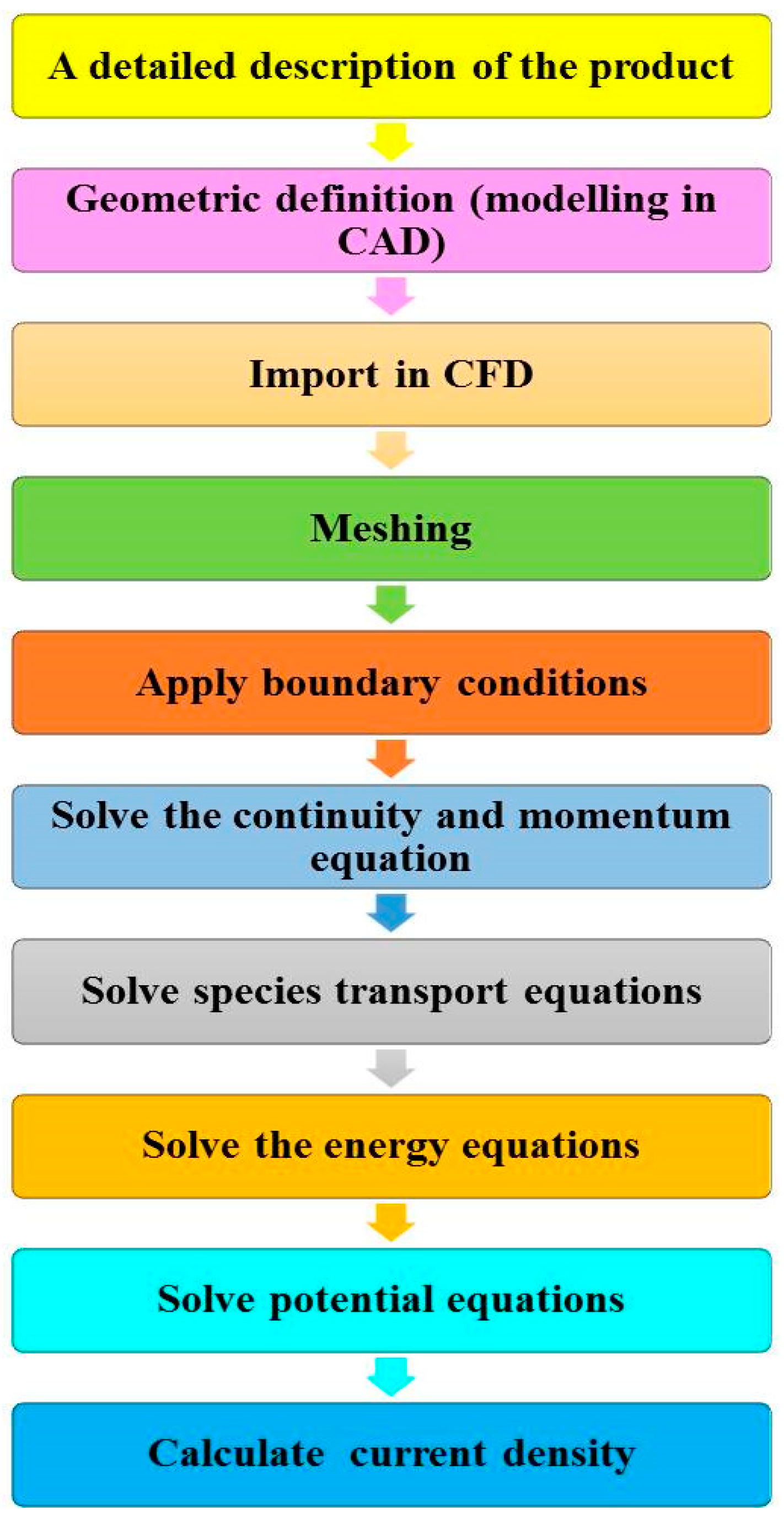
CFD programs consist of three elements: pre-processor, solver, and post-processor. The pre-processor involves the primary processing of input parameters and the design of the fuel cell. In the solver, it solves the problem defined in the pre-processing level with the help of solving the fundamental equations using a numerical calculation; it will calculate the fluid flow, mass, and heat transfer, as well as the electrochemical phenomena of the fuel cell. Finally, the output obtained at the solver level will be processed at the post-processing level and helps to optimize the fuel cell’s performance. The steps involved in CFD are shown in Figure 4. CFD analysis of PCFCs shows more advantages than PCFC experimentation, as it requires less time, low cost, and safety to work. In addition, it speeds up the optimization process of fuel cells more than in the experimentation technique. In PCFCs, it is challenging to study the transport phenomena parameter using experimentation techniques. Hence, researchers showed more interest in computational fluid dynamics techniques for analyzing the performance of fuel cells [52]. It helps to clarify the complex relationship between the transport of reactants/end products and cell performance. With the help of CFD, it is effortless to obtain detailed reports on transport mechanisms and analyze fuel cell performance by overcoming the difficulties faced during the experimental approach [9]. Recently, CFD modeling has been chiefly used in conventional O-SOFCs to analyze and optimize their performance, but its usage in PCFCs is minimal [35]. Hence, researchers have started to implement CFD modeling techniques in PCFCs. PCFCs are not the same as SOFCs; they are operated at intermediate temperatures such as 450–750 °C. Lowering the operating temperature of PCFCs will help to save operating and material costs. The heart of the computational fluid dynamics technique is the fluid’s mathematical and physical laws, such as the conservation equation of mass and energy and thermodynamics law. It helps to calculate the fluid flow, mass and heat transfer, and others by solving the mathematical equation using numerical calculation techniques. CFD modeling helps to figure out what is happening in a cell, including transport processes such as chemical species transport, electron and ion transport, and bulk heat and momentum transfer. These results optimize the PCFC design and operation parameters without needing expensive, tedious, and complicated experiments. Commercial CFD software applications are used for modeling and simulation purposes, such as ANSYS FLUENT, COMSOL MULTIPHYSICS, etc. [36]. ANSYS FLUENT and COMSOL MULTIPHYSICS are mainly used to learn the fuel cell’s behavior in PCFCs. The performance of the PCFC can be obtained by using CFD code to simulate the PCFC performance parameters such as cell dimension, cell structure geometry, thickness, porosity, and thermal stress.

4. Applications of the CFD Modeling in Recent PCFC Models

CFD software is mainly used to analyze fluid flow, heat transfer, and electrochemical reactions in fuel cell stacks by solving governing equations. The collected results will optimize fuel cell engineering design and operational parameters automatically. In recent years, numerous 3D models for fuel cells have played a crucial part in research, and it has been precious to learn what is occurring within the fuel cell stack. PCFCs have a higher working voltage than SOFCs, which significantly increased their modeling studies. Generally, based on the parameters that need to be calculated, CFD models in PCFCs can be classified into 0D, 1D, 2D, and 3D models. For instance, 2D and 3D models are primarily utilized to evaluate cell performance. Two-dimensional models are employed to investigate a fuel cell’s fuel mixture, electrode thickness, temperature, and current density. Similarly, three-dimensional models are incredibly valuable when analyzing the effect of flow distributions, flow topologies, and changes in geometry. Presently, many research works are focused on fabricating novel electrolyte and electrode materials to adapt perfectly to the proton-conducting fuel cell environment. Hence, the fabrication of novel fuel cell materials is most important to develop the effective modeling of the PCFC stack. However, most of the PCFC modeling currently is based on the design optimization of the flow channel of the fuel stack. Here, we summarize the recent CFD modeling employed in PCFCs and its governing equation.

5. Recent PCFC Models Based on Flow-Channel Design

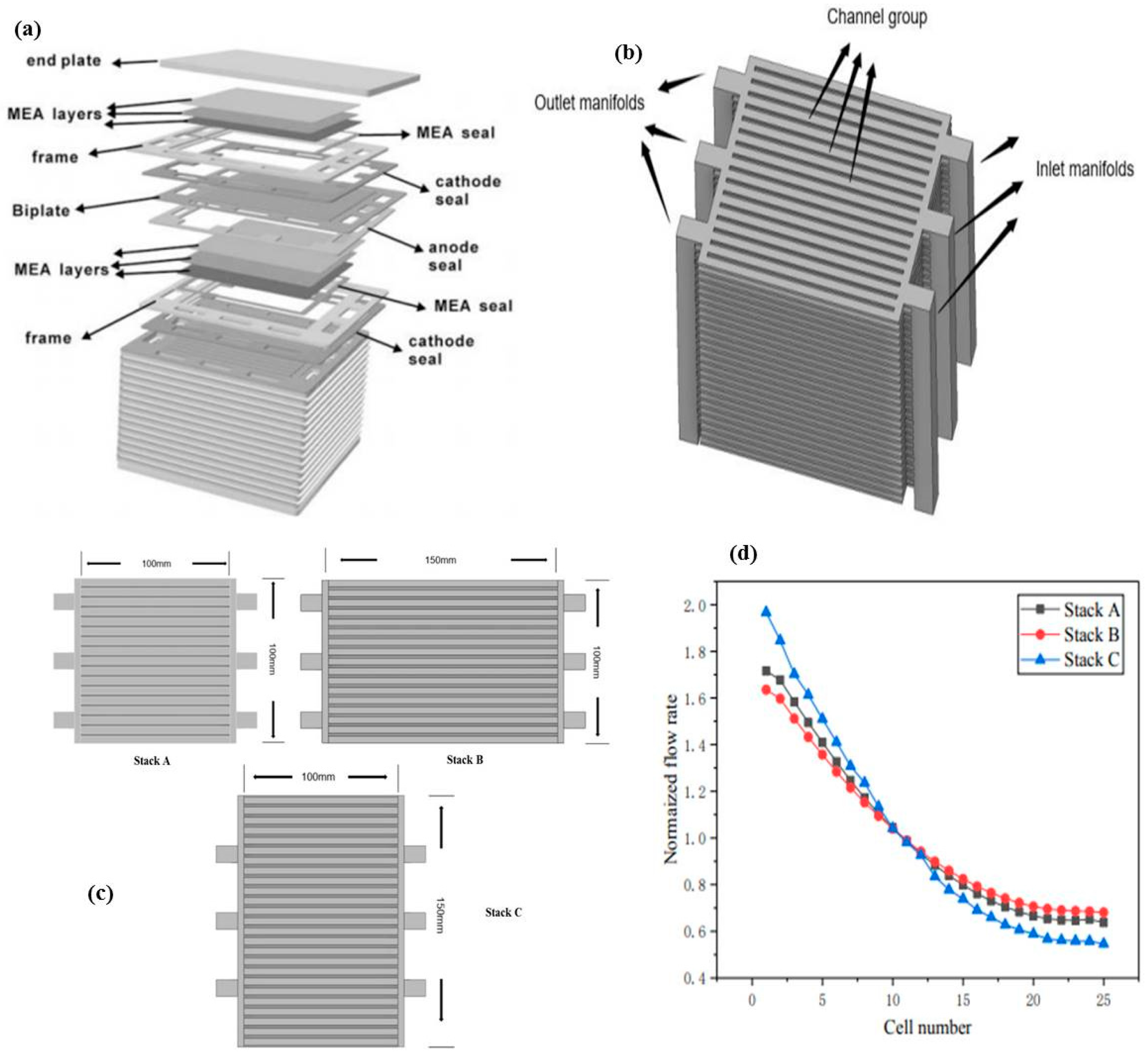
Zhu et al. [53] created a 3D model of a planar-type 25-cell protonic ceramic fuel cell stack to investigate how air flow and species distribution characteristics were influenced by geometric parameters such as changing the membrane electrode assembly area (MEA) length-to-width ratios. The architecture of a standard planar fuel cell with three inlets and outlets was used as the base design to model the 25-cell PCFC stack for their experiment, as shown in Figure 5a [54], and explore its operating phenomenon. It consists of repeating cell units that are coupled in a series manner. Each cell unit consists of primary components such as metal frames, bipolar plates, MEA, and seals. Notably, they focused mainly on the cathode side of the PCFCs, and the 3D design of its fluid flow path in the cathode is shown in Figure 5b [53].
Initially, they analyzed the air-flow and species distribution characteristics in protonic ceramic fuel cell units by designing three stacks (A, B, and C) with various length-to-width ratios of membrane electrode assembly area. Stack A, B, and C had a length-to-width ratio of 1:1, 1.5:1, and 1:1.5, respectively, as shown in Figure 5c [53]. They concluded that the uniformity in the air-flow distribution in the PCFC cells could experience a modest improvement only when the length of the MEA increased to a sufficient limit, not by increasing its width. Notably, stack B mainly showed good uniform distribution with a lower flow rate index of 0.68, compared to other stacks, as shown in Figure 5d [53]. In addition, the PCFC stack was found to have a lower degree of homogeneity in its air-flow rate than an O-SOFC stack with identical structures. Furthermore, the distribution of air-flow over the porous cathode surface was primarily determined by the location of the entry and exit manifolds. Similar to the conventional O-SOFC stack, the air mass flow rate of the stacked layer of a typical PCFC stack decreased as the count of cells increased if the cross-sectional areas of the input and output manifolds remained the same. Furthermore, the areas occupied by the air ribs experienced a low vapor removal rate; this can be enhanced by optimizing the arrangement of the ribs in the PCFC stack.
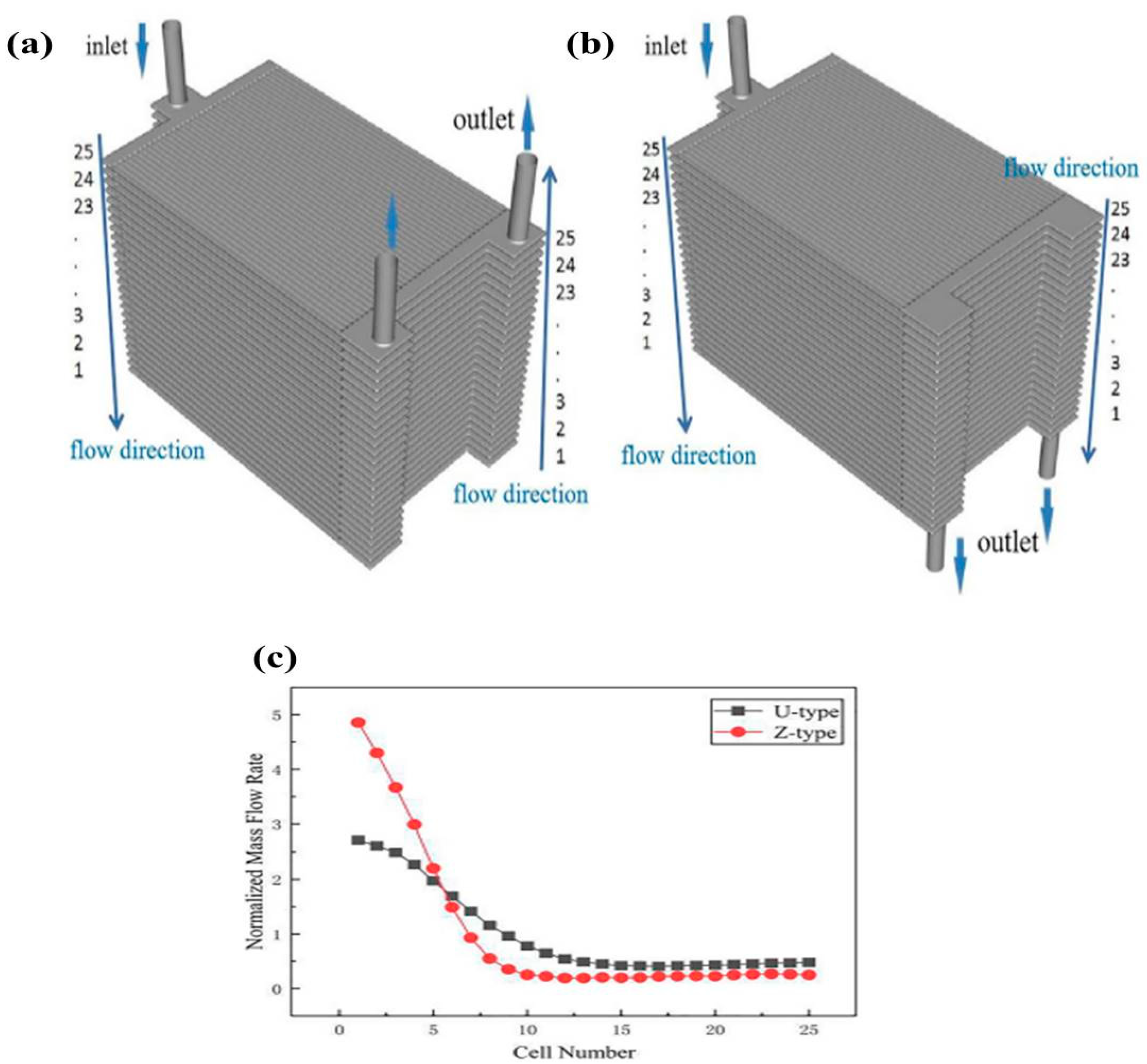
Dai and their team also designed 3D models of PCFC stacks (25 cells) with two types of air-flow routes, such as U-type and Z-type, to investigate the best possible air-flow layout of the PCFC stack, as illustrated in Figure 6a [39]. This three-dimensional model of the air-flow path includes (a) one inlet manifold, (b) thirty-six rib channels to disperse the air-flow throughout the surface of the cell unit, and (c) a porous cathode current collector and function layers to improve the oxidant and product diffusions. If both entry and exit of the inlet and outlet manifolds are situated on the same sides, it can be defined as a U-type path. In the Z-type air-flow pattern, the entrance of the inlet manifold and the exit of the outlet manifold are situated on opposite sides, as shown in Figure 6b [39].
They also constructed SOFC structures with U- and Z-type flow paths to compare and analyze the distribution characteristics with the PCFC stacks. It helps to understand the interconnection that exists between the flow path structure and air-flow species distribution in the PCFC stack. The CFD simulations found that the U-type air-flow path is the superior option for the PCFC stack in terms of achieving higher air and oxygen distribution characteristics compared to the Z-type pattern (as shown in Figure 6c).
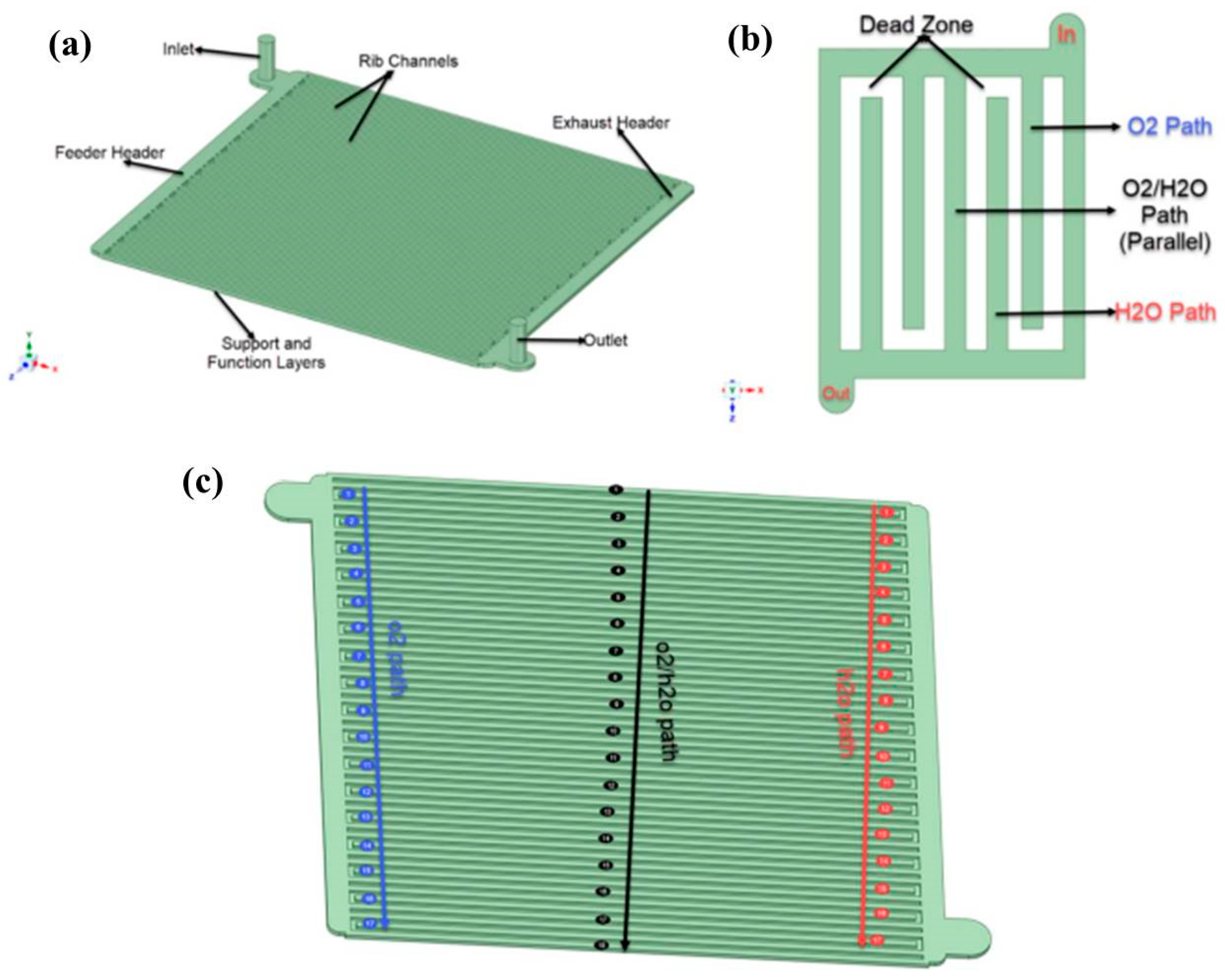
Recently, Akenteng et al. [9] designed a new PCFC model with an inter-parallel flow field (Figure 7a,b) [9]) possessing three unique flow path features to remove water effectively from the cathode side of the PCFC stack. It is also compared with the PCFC stack made up of conventional flow patterns such as serpentine, parallel, and interdigitated flow channel structure. An uneven distribution of water and vapors from the PCFC stack will lead to performance differences not only between cells but also within each cell, which will ultimately result in a reduction in efficiency. They designed a PCFC stack (1 cell) cathode design with an inter-parallel flow field. The structure comprised of a reaction area of 103 × 100 mm2 and one input and output manifold with a 4 mm radius positioned at the borders of the opposing sides of the plates, as shown in Figure 7c [9]. It was found that this design is the most effective one for the cathode side because the PCFC cathode faces more difficulties in high water removal rate, proper O2 transport, and pressure drop than the conventional fuel cell.
In addition, they analyzed the characteristics of PCFCs by changing the position of inlet and outlet manifolds in the inter-parallel flow path. From that, they found that the design with entrance/exit manifolds in the center efficiently distributed oxygen and eliminated water compared to the design with manifolds on the edges of the stack. However, a more even distribution was seen in the stack with the manifold at the edges. Moreover, a stack with one inlet and two outlets helps overcome the pressure drop and is more effective than just one outlet. Thus, adding more outlets can reduce a pressure drop in the PCFC stack.
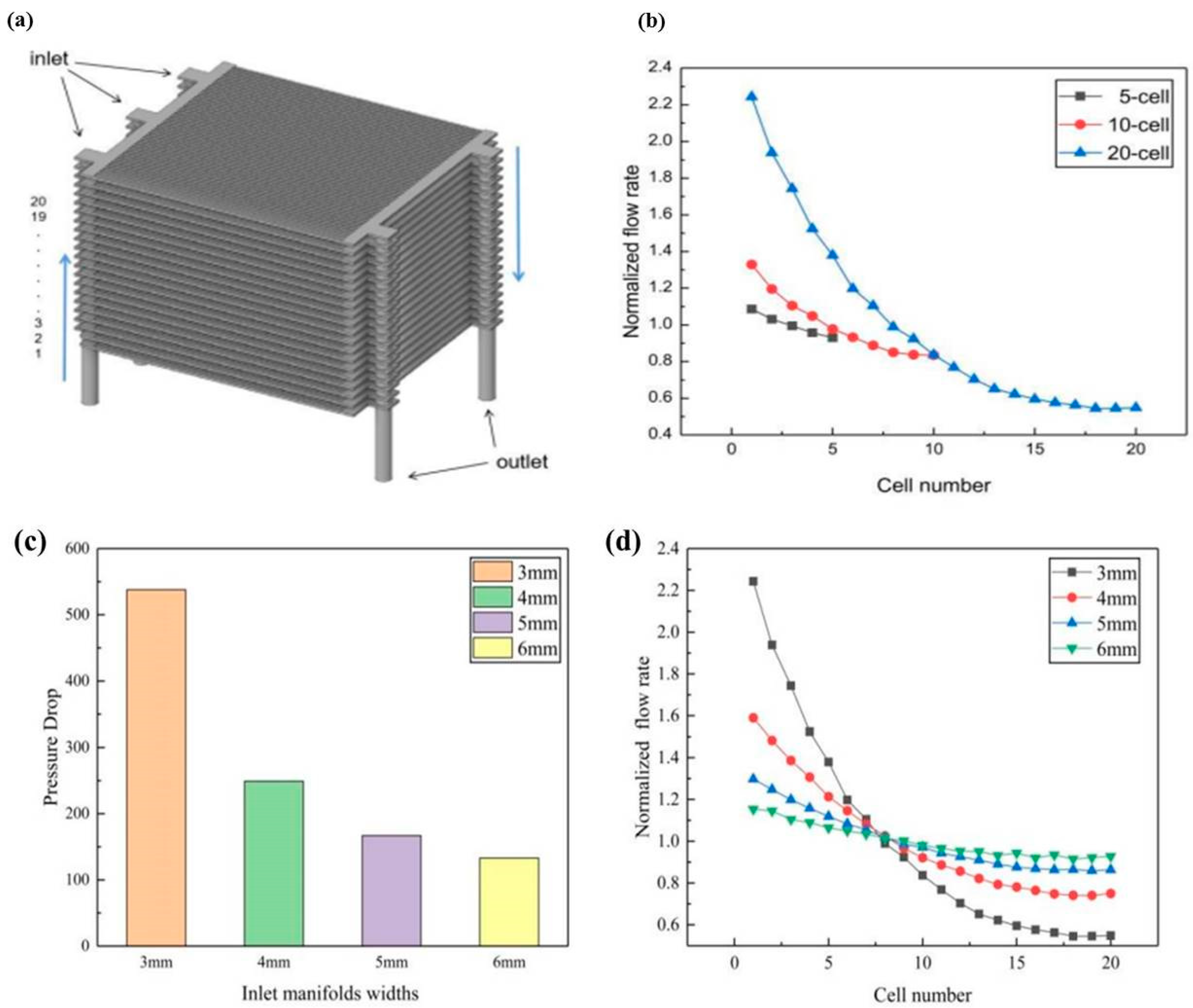
Similarly, Dai et al. [37] also developed a large 3D 20-cell PCFC stack to analyze its fluid dynamics on a large scale. They focused on the dependency and sensitivity of flow distribution uniformity in PCFCs to various geometric variables such as the count of the cell, the manifold’s radius, the header’s width, etc. Figure 8a [37] demonstrates the air-flow and oxygen diffusion pathway of a typical 20-cell protonic ceramic fuel cell stack using a 3D model. This model consists of the following components: (i) three inlet manifolds used to input air-flow into the stacked cell modules; (ii) two outlet manifolds provided to collect the output air and the produced vapors after cathodic chemical reactions; (iii) to disperse the air-flow on the cathode surface of each cell, fifty rib-channels; (iv) cathode current collector layer to avoid heavy concentration loss due to solid interconnect ribs, and cathode functional layer attached to encourage the electrochemical process in the PCFC stack. They used continuity and momentum formulas in order to determine the air-flow rate in the inlet/outlet manifolds of the PCFC stack.
They focused on three crucial observations to show how well the PCFC cathode air flow arrangements are working: the normalized air-flow rate, the minimum flow rate among the stacked cells, and stack pressure loss. Initially, they analyzed the influence of cell numbers (from 5 to 20) on the flow distributions inside the PCFC stack. Figure 8b [37] shows the results of the normalized flow rate in 5, 10, and 20 cells. It was found that when the number of cells in the PCFC stack increases, the flow distribution homogeneity will experience a significant decline. When more vapors are formed within the cathode air flow channel of a PCFC stack, the air-flow distributing uniformity will also suffer as a result. Notably, the PCFC stack with 5 cells has achieved an excellent uniformity index of 0.93 compared to other stacks with 10 cells (0.83) and 20 cells (0.54). Consequently, the flow rate will continue to drop as the number of cells increases. Then, they analyzed the effect of the manifold radius on the PCFC efficiency and found that the pressure drops in the stack were reduced from 537 to 133 pascal when manifold radii increased from 3 to 6 mm. Moreover, the uniformity index (U) was also improved by increasing the manifold radii; the values of U on 3, 4, 5, and 6 mm are 0.53, 0.74, 0.85, and 0.91, respectively.
In addition, they observed normalized flow rate distributions over the cathode surface on the PCFC unit by changing the feed/exhaust header widths to 2.5, 5, and 10 mm, as shown in Figure 8c,d [37]. They concluded that varying header width would improve flow distribution characteristics on the cathode layer of each PCFC unit, but its effect is very minimal in the stacked unit. The findings of this research have the potential to supply us with beneficial guidelines for the further improvement of the PCFC stack technique in the future. Table 2 represents the various CFD models employed to analyze the characteristics of the PCFC stack.

6. Recent PCFC Models Based on Cathode Layer Thickness

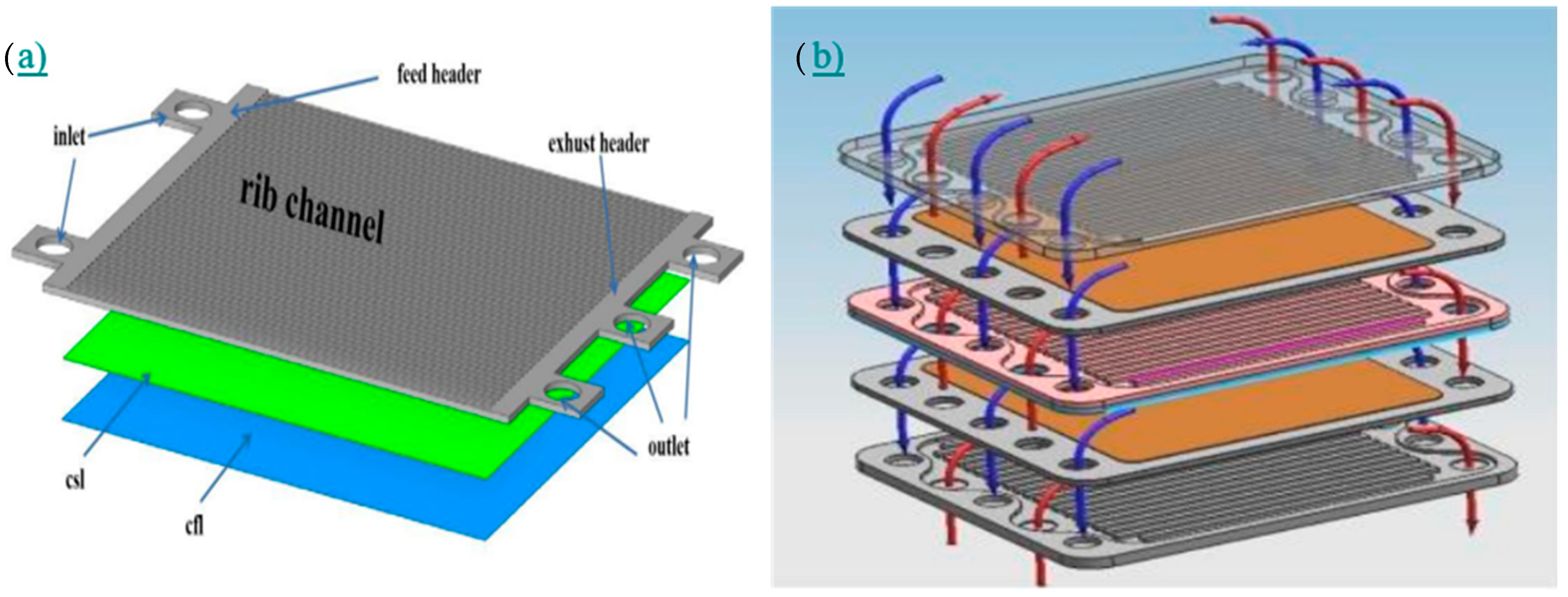
Recently, some researchers performed some modeling work on the varying thickness range of the cathode layer and evaluated the performance of the PCFC. Mainly, Dai et al. designed a PCFC stack consisting of 5-cells, as shown in Figure 9a [55]. Using the CFD approach, they analyzed the influence of geometric parameters of the rib channels and cathode thickness/width on the oxygen transport and vapor removal characteristics inside the cathode components of the PCFC stack. This 3D model of PCFC comprises three air outlet manifolds, rib channels, feed/exhaust headers, two air inlet manifolds, and a cathode support layer with a functional layer. They employed the continuity equation as the equation for the conservation of momentum in PCFC stacks.
Initially, simulations focused on analyzing the oxygen distribution over the thick electrolyte surface in a 5-cell PCFC stack by adjusting the rib channel width from 2 to 4 mm. They found that increasing the width of the rib channels to a sufficient size would considerably improve the quality of oxygen distribution across the thick electrolyte surface. It performed well as compared to the same PCFC stack with narrower rib channel width. This is because a wider rib channel width results in a larger contact region between the rib channels and the porous cathode, which reduces oxygen transport resistance. It is seen in Figure 9b [55].
In particular, the authors analyzed the effects of varying the cathode layer thickness as 0.01, 0.02, and 0.03 mm on the oxygen and vapor distributions in a 5-cell PCFC stack. They found that increasing the PCFC cathode thickness could significantly increase the oxygen distribution properties over the rich electrolyte surface. It will also boost the PCFC stack’s electrochemical efficiency. Moreover, it can lessen the resistance encountered during the vapor transmission created by the electrochemical reactions at the PCFC cathode. It stands to reason that the oxygen supply and vapor removal capability will be poor if the PCFC cathode is too thin and porous. This study’s findings helped to enhance our understanding of technical matters and encouraged the development of the PCFC stack, ultimately leading to the acquisition of an acceptable stack design.
Similarly, Zheng Li and their team [56] analyzed the effect of varying cathode thickness and its microstructural characteristics on the performance of the PCFC stack. They developed a percolation theory to examine the microstructural effects of the cathode. This model attempts to explain the complicated interplay between the cathode’s features and the efficiency of the PCFC. The simulation results determined that the cathode thickness should fall between 120 to 200 mm. An overly thin cathode could impair the average cell’s output due to the localized inefficiency under the rib caused by the localized low oxygen concentration. In addition, it was established that the cathode’s efficiency could be increased by over 9%, and gas distribution homogeneity could be increased by 22.5% merely by raising the cathode material’s porosity from 0.3 to 0.5. When the cathode particle size was increased from 0.1 mm to 0.2 mm, oxygen distribution was increased by nearly 50% under the rib. This model is an important technique that can be utilized to direct the manufacturing of PCFC cathodes as well as the design of the innovative interconnect topology.

7. Governing Equations Used in PCFC Models

Before developing the model, it is necessary to have good knowledge about the governing equations employed in modeling the PCFCs. It helps to estimate fuel cell attributes such as temperatures, pressures, gas velocities, liquid flows, reactant transport, and electrical potentials [57]. In addition, some additional equations are required when fuel cell conditions are examined in three dimensions. Notably, to find a solution to the transport processes, CFD solves several systems of equations commonly used in the PCFC systems, some of which are listed below [36,37,56,58].
  • Mass continuity equations
  • Momentum conservation equations
  • Proton and electron transport
  • Electrochemical reactions
  • Energy conservation equations
The following is a list of the specific equations that the ANSYS Fluent solver will attempt to approach while it is operating.
Continuity:
ρ u x + ρ v y + ρ w z = S m  
where,
  • u = local fluid velocity in the x-direction (m/s)
  • v = local fluid velocity in the y-direction (m/s)
  • w = local fluid velocity in the z-direction (m/s)
  • ρ = local fluid density (kg/m3)
  • Sm = mass source term (kg/m3 s)
Momentum Transport:
u ρ u x + v ρ u y + w ρ u z = P x + x   µ u x   + y µ u y   + z µ u z   + s p x  
It is shown in the x-direction. Equations for y- and z-directions are the same.
Where,
  • µ = local fluid dynamic viscosity (s/m2)
  • P = local fluid pressure (N/m2)
  • Sp = source term, momentum (N/m3)
Energy:
x ρ C T x + v ρ C T y + w ρ C T z = x k T x + y k T y + z k T z + S h  
where,
  • C = specific heat capacity (s/m2)
  • T = local fluid temperature (K)
  • k = effective conductivity (W/mK)
  • Sh = source term, heat energy (W/m3)
Mass Transfer:
u ρ y i x + v ρ y i y + w ρ y i z = J x , i x + J y , i y + J z , i z + S i    
where,
  • i = mass diffusion coefficient species at anode and cathode
  • u , v , w = velocity vector (m/s)
  • ρ = density (kg/m3)
  • J = Diffusion rate of species i depends on mass in various directions (kg m−2 s −1)
  • Si = Source term of species i resulting from a chemical process (mol m−2 s −1)
Charge Transport:
· i p r o = · ( σ p r o ,   e f f   φ p r o ) = i 0   λ T P B V  
· i e l e = · ( σ e l e ,   e f f   φ ele ) = i 0   λ T P B V
where,
  • ipro = protonic current vectors (A)
  • iele = electronic current vectors (A)
  • 𝜎pro, eff = effective conductivity for proton transport (W/m K)
  • 𝜎ele, eff= effective conductivity for electron transport (W/m K)
  • φ = potential (V)
  • i0 = current density (A/m2)
  • λ T P B V = triple phase boundary length per volume (m/m3)
Current Density:
i an = i 0 , an   ( e x p α a n n F η a c t , a n R T     e x p ( 1 α a n ) n F η a c t , a n R T )
i ca = i 0 , ca   ( e x p α c a n F η a c t , c a R T   e x p ( 1 α c a ) n F η a c t , c a R T )
where,
  • αan, αca = transfer coefficient for anode and cathode (dimensionless)
  • 𝜂act,an, 𝜂act,ca= activation loss for anode and cathode (V)
  • i0,an, i0,ca = exchange current density for anode and cathode (A/m2)
  • n = transmitted electrons in the reaction
  • F = faraday constant (9.65 × 10⁷ C/k mol)
  • R= universal molar gas constant (8.314 J/mol k)
  • T = temperature (K)
Gas-Phase Species Diffusivity:
D i j e f f = ε τ   3.198 × 10 8 T 1.75 P + v i 1 3 + v j 1 3 2 1 M i + 1 M j 0.5  
D i k e f f = ε τ   2 3   r p   8 R T π M i ˙
where,
  • D i j e f f = Effective binary diffusion coefficient (m2 s−1)
  • D i k e f f = Effective Knudsen diffusion coefficient of species i, (m2 s−1)
  • ε   = Porosity
  • τ = tortuosity
  • r p = mean pore radius (m)
  • T =Temperature (K)
  • R = universal molar gas constant (8.314 J/mol k)
  • Mi, Mj = molecular mass (g)
  • v i , v j = diffusion volume
  • P = pressure (N/m2)
The below equation calculates the uniformity index ( U ) to identify the air-flow distribution in the cell stack.
U = min m 1   : m N ,   m i = m I ˙ a v e m 1 : m N  
where,
  • m i = minimum value of the normalized air flow rates (kg/s)
  • mi = air flow mass rate at the ith layer (kg/s)
  • N = number of stacks
  • ave (m1:mN) = average air mass flow rate at each cell unit (kg/s).

8. Comparison of Modeling of SOFC with PCFC

Apart from the equations mentioned above, it is essential to have a comparative analysis of O-SOFC modeling works with PCFCs so that many inputs/ideas can be obtained to enhance PCFC modeling in the future. Most of the PCFC modeling works were just replicating the O-SOFC modeling works because, as per the modeling perspective, the design of the PCFC stack is almost similar to O-SOFCs. It has been found that SOFC modeling is well developed compared to other fuel cells. Only a few modeling papers were published based on PCFCs. Moreover, many articles were published based on modeling the O-SOFCs using various types of software such as ANSYS, COMSOL MULTIPHYSICS, MATLAB, C++., etc. Therefore, many factors need to be taken as input from the reported modeling works of O-SOFCs while modeling the PCFC stacks in the future. Mainly, N. Alhazmi et al. [59] designed button-type O-SOFCs and studied their performances at various working temperatures and fuel flow rates. They found that the current density of the designed button-type O-SOFCs was improved significantly to about 108.5% at an average voltage of 0.6 V by operating the cell at a temperature of 1023 K, as well as the oxygen and hydrogen flow rates were maintained at 0.6 L min−1 and 1.8 L min−1. In addition, it has been found that there are different structures (tubular, button-type) of SOFCs, which were designed and analyzed its behavior through CFD modeling and experimentally [60]. However, in PCFCs, only planar-type stacks were modeled and studied for behavior. Therefore, it is necessary to adopt the different structures in PCFCs to enhance their applications further.
Moreover, most of the PCFC modeling works were primarily focused on the cathode region of the cell and analyzed the uniform distribution of fuels, pressure, water, and temperatures in that region during operation. Currently, no studies have focused on the complete structure of the PCFCs, and their characteristics have been analyzed under various operating temperatures and fuel ratios. Hence, designing whole cells and analyzing their behavior under different operating temperatures and fuel ratios is essential to enhance PCFC technology. In SOFCs, both the cathode and anode sections have been given equal importance during modeling. In addition, various types of commercial software were employed to conduct different analyses of the O-SOFCs. For instance, electrochemical and flow analysis can be carried out using ANSYS user-defined functions or the SOFC add-on module. With the help of these functions, a lot of studies were carried out in SOFCs, such as current density distribution, thermal boundary conditions, effects of radiative heat transfer, stress analysis, etc.
Similarly, the finite element method (FEM) was employed in ANSYS to carry out the creep behavior, compressive stress tests, etc., in the O-SOFCs. Then, Sasanka N et al. [61] also used COMSOL MULTIPHYSICS to perform simulations to find the influence of gas flow patterns (radial- and counter-type) in various working temperatures for anode-supported planar O-SOFCs. They used built-in formulas of COMSOL MULTIPHYSICS to carry out the multi-component transport (Maxwell–Stefan diffusion and convection equations), charge balances (Ohm’s law & Butler–Volmer charge transfer kinetics), and gas diffusion (Navier–Stokes and Brinkman equations) simulations. In addition, Lakshmi et al. [62] designed single-cell O-SOFCs and employed MATLAB/SIMULINK to analyze the steady-state characteristics of the cell at various fuel flow rates at different working temperatures. Table 3 represents the different types of modeling analyses that have been carried out in SOFCs using multiple kinds of commercial software. Hence, it is necessary to consider the CFD modeling of SOFCs while modeling the PCFCs in the future. It is believed to speed up the fabrication, testing, and commercialization of PCFC systems.

9. Research Gap and Future Outlook

Traditional fuel cells, such as SOFCs, have attracted considerable interest because of their reduced carbon emissions and higher conversion efficiency than conventional thermal power generation. In addition, it demonstrates numerous benefits, including adaptability, solid electrolyte/non-precious metal catalyst utilization, and quick electrochemical reaction kinetics. However, it works with the help of oxygen ion conducting electrolytes, which needs a high operating temperature of more than 800 °C. Due to this, materials employed in the SOFCs should have suitable expansion coefficients to reduce the amount of thermal stress induced and requires good thermal and mechanical stability during the extended period of higher operating temperature conditions. Therefore, the protonic ceramic fuel cell is a promising alternative to high-temperature fuel cells because its operating temperature is around 400 to 750 °C. This characteristic helps to increase the fuel cell efficiency and stability. PCFCs have more advantages than other fuel cells, such as high power density, less weight, fast startup, high flexibility, long lifetime, and compact size. PCFCs are the same as conventional oxygen-ion conducting fuel cells; here, the water is produced on the cathode side, but in SOFCs is produced on the anode. A PCFC is a multi-component device that concurrently carries out a range of physical and chemical operations. It is challenging from a scientific standpoint to properly represent such a complicated system, necessitating creative mathematical and numerical methodologies. The challenge lies not just in the sophisticated mathematical formulations required to explain the physical and electrochemical processes but, perhaps more importantly, in our poor knowledge of these processes.
Consequently, most modeling research works are based on crude empirical formulations, constants, and/or 1D simplifications for some essential PCFC processes. Although the overall performance characteristics of a fuel cell can be replicated, the exact output of a fuel cell cannot be duplicated. It requires a lot of research to construct process-specific submodels that can accurately anticipate the efficiency of PCFCs. Therefore, a few recommendations have been made in a few domains which need to be considered in future modeling works of the PCFCs:
  • Firstly, the CFD modeling work based on PCFCs is limited and merely a reflection of the modeling work previously utilized for SOFCs. This is because the majority of PCFC electrode and electrolyte components were already used in conventional solid oxide fuel cells. Therefore, extensive research should be conducted to develop new materials and designs for PCFCs in order to advance the protonic ceramic fuel cell modeling process.
  • The numerical modeling of water formation and transportation within PCFCs presents a substantial difficulty. Specifically, interactions between water molecules and ions are crucial variables, although they are not yet fully understood; hence, molecular dynamics may be valuable for elucidating the transport of water and its ions in electrolytes and electrodes. In addition, special attention should be made by making specialized and novel submodels to capture the condensation/vaporization and liquid water transport in the GDL and catalyst section.
  • To increase the efficiency of the PCFC, it is necessary to comprehend that catalytic electrochemical reactions occur within the PCFC; hence, a unique catalytic CFD modeling analysis should be conducted in addition to the usual electrochemical CFD analysis.
  • Most theoretical PCFC models focus on examining steady-state conditions; however, transient transport behaviors must be considered in future designs. In addition, due to the computational demands of PCFCs with complex flow fields, greater emphasis has been placed on simple flow fields and channels, making complex flow field problems challenging to resolve.
  • The most crucial obstacle in fuel cell modeling is collecting the necessary data for input into the CFD model and validating it in the form of test results, including the thermal and physical characteristics of the materials. Even though PCFC modeling technology has a lot of promise, it is challenging to create because of the lack of a reliable, all-encompassing modeling technique that correctly represents the fuel cell’s many qualitative and statistical processes. Usually, it can be achieved by comparing the CFD model predictions obtained from the verified input against precise measurement results. However, precise experiment findings from testing fuel cell stacks are extremely restricted at present. In addition, the CFD model necessitates multiple material data, which are exceedingly challenging to attain. It makes fuel cell designing more challenging to conduct accurate measurements. In addition to limiting the general public’s access to a portion of the available data, the major necessity for business concerns significantly restricts the public’s access to other data. Consequently, most fuel cell designs now require experimental data/inputs, specifically thorough measurement data/output, to validate the designed models and their predictions. This circumstance continues to restrict the activity of fuel cell modeling.

10. Summary

In summary, interest in CFD is growing every day because computer modeling enables the evaluation of innovative designs and the assessment of the performance of the PCFCs. The ability of CFD to predict the performance of PCFCs in the future will boost their marketability, dependability, and confidence among designers. Several fundamental issues, such as diffusion of species through the electrode materials, analysis of the catalytic electrochemical process, transient process, water and gas management, etc., should require deep research. To improve the modeling analysis and performance of PCFCs, it involves collaboration/partnership between numerical designers and experimentalists as well as between academics and industrialists. In the future, when more precise PCFC sub- models are developed through CFD, then CFD modeling approaches will likely emerge as one of the most cost-effective approaches to aid in creating novel PCFC technologies with high adaptability, efficiency, and precision.

Author Contributions

Conceptualization, A.D. and A.K.A.; methodology, A.D., Y.S. and A.K.A.; validation, Y.S., A.D. and L.A.O.; formal analysis, A.D.; data curation Y.S., A.D. and L.A.O.; writing—original draft preparation, A.D.; Visualization M.A.S.; writing—review and editing, M.A.S., A.D., V.R., H.P.H.M.Y. and A.K.A.; supervision, V.R. and A.K.A. All authors have read and agreed to the published version of the manuscript.

Funding

This research received no external funding.

Data Availability Statement

Not applicable.

Acknowledgments

The authors Y.S., A.D., and L.A.O. acknowledge the support from Universiti Brunei Darussalam through University Graduate Scholarship.

Conflicts of Interest

The authors declare no conflict of interest.

References

  1. Longo, S.; Cellura, M.; Guarino, F.; Brunaccini, G.; Ferraro, M. Life Cycle Energy and Environmental Impacts of a Solid Oxide Fuel Cell Micro-CHP System for Residential Application. Sci. Total Environ. 2019, 685, 59–73. [Google Scholar] [CrossRef]
  2. Strazza, C.; del Borghi, A.; Costamagna, P.; Traverso, A.; Santin, M. Comparative LCA of Methanol-Fuelled SOFCs as Auxiliary Power Systems on-Board Ships. Appl. Energy 2010, 87, 1670–1678. [Google Scholar] [CrossRef]
  3. Radenahmad, N.; Tasfiah, A.; Saghir, M.; Taweekun, J.; Saifullah, M.; Bakar, A.; Reza, S.; Azad, A.K. A Review on Biomass Derived Syngas for SOFC Based Combined Heat and Power Application. Renew. Sustain. Energy Rev. 2020, 119, 109560. [Google Scholar] [CrossRef]
  4. Mohd Nazrul Aman, N.A.; Muchtar, A.; Somalu, M.R.; Rosli, M.I.; Baharuddin, N.A.; Kalib, N.S. A Short Review on the Modeling of Solid-Oxide Fuel Cells by Using Computational Fluid Dynamics: Assumptions and Boundary Conditions. Int. J. Integr. Eng. 2018, 10, 87–92. [Google Scholar] [CrossRef] [Green Version]
  5. Anwar, M.; Sa, M.A.; Muchtar, A.; Somalu, M.R. Influence of Strontium Co-Doping on the Structural, Optical, and Electrical Properties of Erbium-Doped Ceria Electrolyte for Intermediate Temperature Solid Oxide Fuel Cells. Ceram. Int. 2019, 45, 5627–5636. [Google Scholar] [CrossRef]
  6. Kang, E.H.; Choi, H.R.; Park, J.S.; Kim, K.H.; Kim, D.H.; Bae, K.; Prinz, F.B.; Shim, J.H. Protonic Ceramic Fuel Cells with Slurry-Spin Coated BaZr0.2Ce0.6Y0.1Yb0.1O3- δ Thin-Film Electrolytes. J. Power Sources 2020, 465, 228254. [Google Scholar] [CrossRef]
  7. Radenahmad, N.; Afif, A.; Petra, P.I.; Rahman, S.M.H.; Eriksson, S.G.; Azad, A.K. Proton-Conducting Electrolytes for Direct Methanol and Direct Urea Fuel Cells–A State-of-the-Art Review. Renew. Sustain. Energy Rev. 2016, 57, 1347–1358. [Google Scholar] [CrossRef]
  8. Hossain, S.; Abdalla, A.M.; Jamain, S.N.B.; Zaini, J.H.; Azad, A.K. A Review on Proton Conducting Electrolytes for Clean Energy and Intermediate Temperature-Solid Oxide Fuel Cells. Renew. Sustain. Energy Rev. 2017, 79, 750–764. [Google Scholar] [CrossRef]
  9. Akenteng, Y.D.; Yang, X.; Zhao, Y.; Lysyakov, A.; Matveev, A.; Chen, D. Computational Fluid Dynamics Modeling of an Inter-Parallel Flow Field for Proton Ceramic Fuel Cell Stack. Ionics 2022, 28, 3367–3378. [Google Scholar] [CrossRef]
  10. Klein, J.M.; Bultel, Y.; Georges, S.; Pons, M. Modeling of a SOFC Fuelled by Methane: From Direct Internal Reforming to Gradual Internal Reforming. Chem. Eng. Sci. 2007, 62, 1636–1649. [Google Scholar] [CrossRef]
  11. Xu, Q.; Guo, Z.; Xia, L.; He, Q.; Li, Z.; Temitope Bello, I.; Zheng, K.; Ni, M. A Comprehensive Review of Solid Oxide Fuel Cells Operating on Various Promising Alternative Fuels. Energy Convers. Manag. 2022, 253, 115175. [Google Scholar] [CrossRef]
  12. Pan, Y.; Zhang, H.; Xu, K.; Zhou, Y.; Zhao, B.; Yuan, W.; Sasaki, K.; Choi, Y.; Chen, Y.; Liu, M. A High-Performance and Durable Direct NH3 Tubular Protonic Ceramic Fuel Cell Integrated with an Internal Catalyst Layer. Appl. Catal. B 2022, 306, 121071. [Google Scholar] [CrossRef]
  13. Afif, A.; Radenahmad, N.; Cheok, Q.; Shams, S.; Kim, J.H.; Azad, A.K. Ammonia-Fed Fuel Cells: A Comprehensive Review. Renew. Sustain. Energy Rev. 2016, 60, 822–835. [Google Scholar] [CrossRef]
  14. Abdalla, A.M.; Hossain, S.; Nisfindy, O.B.; Azad, A.T.; Dawood, M.; Azad, A.K. Hydrogen Production, Storage, Transportation and Key Challenges with Applications: A Review. Energy Convers. Manag. 2018, 165, 602–627. [Google Scholar] [CrossRef]
  15. Naeem Khan, M.; Azad, A.K.; Savaniu, C.D.; Hing, P.; Irvine, J.T.S. Robust Doped BaCeO3-δ Electrolyte for IT-SOFCs. Ionics 2017, 23, 2387–2396. [Google Scholar] [CrossRef] [Green Version]
  16. Chen, M.; Zhou, M.; Liu, Z.; Liu, J. A Comparative Investigation on Protonic Ceramic Fuel Cell Electrolytes BaZr0.8Y0.2O3-δ and BaZr0.1Ce0.7Y0.2O3-δ with NiO as Sintering Aid. Ceram. Int. 2022, 48, 17208–17216. [Google Scholar] [CrossRef]
  17. Azim Jais, A.; Muhammed Ali, S.A.; Anwar, M.; Rao Somalu, M.; Muchtar, A.; Wan Isahak, W.N.R.; Yong Tan, C.; Singh, R.; Brandon, N.P. Enhanced Ionic Conductivity of Scandia-Ceria-Stabilized-Zirconia (10Sc1CeSZ) Electrolyte Synthesized by the Microwave-Assisted Glycine Nitrate Process. Ceram. Int. 2017, 43, 8119–8125. [Google Scholar] [CrossRef]
  18. Anwar, M.; Sa, M.A.; Baharuddin, N.A.; Raduwan, N.F.; Muchtar, A.; Somalu, M.R. Structural, Optical and Electrical Properties of Ce0.8Sm0.2-Er O2- (X=0–0.2) Co-Doped Ceria Electrolytes. Ceram. Int. 2018, 44, 13639–13648. [Google Scholar] [CrossRef]
  19. Rasaki, S.A.; Liu, C.; Lao, C.; Chen, Z. A Review of Current Performance of Rare Earth Metal-Doped Barium Zirconate Perovskite: The Promising Electrode and Electrolyte Material for the Protonic Ceramic Fuel Cells. Prog. Solid State Chem. 2021, 63, 100325. [Google Scholar] [CrossRef]
  20. Duan, C.; Tong, J.; Shang, M.; Nikodemski, S.; Sanders, M.; Ricote, S.; Almansoori, A.; O’Hayre, R. Readily Processed Protonic Ceramic Fuel Cells with High Performance at Low Temperatures. Science 2015, 349, 1321–1326. [Google Scholar] [CrossRef]
  21. Atkinson, A.; Barnett, S.; Gorte, R.J.; Irvine, J.T.S.; McEvoy, A.J.; Mogensen, M.; Singhal, S.C.; Vohs, J. Advanced Anodes for High-Temperature Fuel Cells. Nat. Mater. 2004, 3, 17–27. [Google Scholar] [CrossRef] [PubMed] [Green Version]
  22. Goodenough, J.B.; Huang, Y.H. Alternative Anode Materials for Solid Oxide Fuel Cells. J. Power Sources 2007, 173, 1–10. [Google Scholar] [CrossRef]
  23. Minh, N.Q. Solid Oxide Fuel Cell Technology–Features and Applications. Solid. State Ion. 2004, 174, 271–277. [Google Scholar] [CrossRef]
  24. Ding, K.; Zhu, M.; Han, Z.; Kochetov, V.; Lu, L.; Chen, D. Momentum-Species-Heat-Electrochemistry Distribution Characteristics within Solid Oxide Fuel Cell Stack with Complex Inter-Digital Fuel Channels. Ionics 2020, 26, 4567–4578. [Google Scholar] [CrossRef]
  25. Afif, A.; Radenahmad, N.; Rahman, S.M.H.; Torino, N.; Saqib, M.; Hossain, S.; Park, J.Y.; Azad, A.K. Ceramic Fuel Cells Using Novel Proton-Conducting BaCe0.5Zr0.3Y0.1Yb0.05Zn0.05O3-δ Electrolyte. J. Solid State Electrochem. 2022, 26, 111–120. [Google Scholar] [CrossRef]
  26. Hossain, S.; Abdalla, A.M.; Zaini, J.H.; Savaniu, C.D.; Irvine, J.T.S.; Azad, A.K. Highly Dense and Novel Proton Conducting Materials for SOFC Electrolyte. Int. J. Hydrogen Energy. 2017, 42, 27308–27322. [Google Scholar] [CrossRef] [Green Version]
  27. Afif, A.; Radenahmad, N.; Lim, C.M.; Petra, M.I.; Islam, M.A.; Rahman, S.M.H.; Eriksson, S.; Azad, A.K. Structural Study and Proton Conductivity in BaCe0.7Zr0.25−xYxZn0.05O3 (x = 0.05, 0.1, 0.15, 0.2 & 0.25). Int. J. Hydrogen Energy 2016, 41, 11823–11831. [Google Scholar] [CrossRef]
  28. Azad, A.K.; Abdalla, A.M.; Afif, A.; Azad, A.; Afroze, S.; Idris, A.C.; Park, J.Y.; Saqib, M.; Radenahmad, N.; Hossain, S.; et al. Improved Mechanical Strength, Proton Conductivity and Power Density in an ‘All-Protonic’ Ceramic Fuel Cell at Intermediate Temperature. Sci. Rep. 2021, 11, 19382. [Google Scholar] [CrossRef]
  29. Radenahmad, N.; Afif, A.; Abdalla, A.M.; Saqib, M.; Park, J.Y.; Zaini, J.; Irvine, J.; Kim, J.H.; Azad, A.K. A New High-Performance Proton-Conducting Electrolyte for Next-Generation Solid Oxide Fuel Cells. Energy Technol. 2020, 8, 2000486. [Google Scholar] [CrossRef]
  30. Radenahmad, N.; Afroze, S.; Afif, A.; Azad, A.T.; Shin, J.S.; Park, J.Y.; Zaini, J.H.; Azad, A.K. High Conductivity and High Density SrCe0.5Zr0.35Y0.1A0.05O3-δ (A = Gd, Sm) Proton-Conducting Electrolytes for IT-SOFCs. Ionics 2020, 26, 1297–1305. [Google Scholar] [CrossRef]
  31. Hossain, S.; Abdalla, A.M.; Radenahmad, N.; Zakaria, A.K.M.; Zaini, J.H.; Rahman, S.M.H.; Eriksson, S.G.; Irvine, J.T.S.; Azad, A.K. Highly Dense and Chemically Stable Proton Conducting Electrolyte Sintered at 1200 °C. Int. J. Hydrogen Energy 2018, 43, 894–907. [Google Scholar] [CrossRef] [Green Version]
  32. Afif, A.; Radenahmad, N.; Zaini, J.; Abdalla, A.M.; Rahman, S.M.H.; Eriksson, S.; Azad, A.K. Enhancement of Proton Conductivity through Yb and Zn Doping in BaCe0.5Zr0.35Y0.15O3-δ Electrolyte for IT-SOFCs. Process. Appl. Ceram. 2018, 12, 180–188. [Google Scholar] [CrossRef] [Green Version]
  33. Radenahmad, N.; Afif, A.; Petra, M.I.; Rahman, S.M.H.; Eriksson, S.; Azad, A.K. High Conductivity and High Density Proton Conducting Ba1−xSrxCe0.5Zr0.35Y0.1Sm0.05O3−δ (x = 0.5, 0.7, 0.9, 1.0) Perovskites for IT-SOFC. Int. J. Hydrogen Energy 2016, 41, 11832–11841. [Google Scholar] [CrossRef]
  34. Khan, M.N.; Savaniu, C.D.; Azad, A.K.; Hing, P.; Irvine, J.T.S. Wet Chemical Synthesis and Characterisation of Ba 0.5 Sr 0.5 Ce 0.6 Zr 0.2 Gd 0.1 Y 0.1 O 3−δ Proton Conductor. Solid State Ion. 2017, 303, 52–57. [Google Scholar] [CrossRef] [Green Version]
  35. Malik, L.A.; Sina, A.L.; Osmana, N.; Hassanc, O.H.; Jani, A.M. Short Review on the Suitability of CFD Modeling for Proton Conducting Fuel Cell Performance. J. Kejuruter. 2020, 32, 587–590. [Google Scholar]
  36. Muchtar, A.; Aman, N.A.; Somalu, M.R.; Rosli, M.I.; Kalib, N.S. Overview of Computational Fluid Dynamics Modelling in Solid Oxide Fuel Cell. J. Adv. Res. Fluid Mech. Therm. Sci. 2020, 52, 174–181. [Google Scholar]
  37. Dai, J.Q.; Zhu, M.F.; Zhang, H.Z.; Liu, J.P.; Chen, D.F. The Effect of the Geometric Parameters on the Air Flow Distrib Ution Uniformity within the Protonic Ceramic Fuel Cell Stack. Int. J. Electrochem. Sci. 2021, 16, 211052. [Google Scholar] [CrossRef]
  38. Blum, L.; de Haart, L.G.J.B.; Malzbender, J.; Menzler, N.H.; Remmel, J.; Steinberger-Wilckens, R. Recent Results in Jülich Solid Oxide Fuel Cell Technology Development. J. Power Sources 2013, 241, 477–485. [Google Scholar] [CrossRef]
  39. Dai, J.Q.; Yang, Z.M.; Wang, W.S.; Liu, J.P.; Akenteng, Y.D.; Chen, D.F. Study the Flow and Species Distribution Characteristics in a Typical 25-Cell Proton Ceramic Fuel Cell Stack by 3D Large-Scale Modeling. Ionics 2022, 28, 1863–1872. [Google Scholar] [CrossRef]
  40. Barbir, F. PEM Fuel Cells: Theory and Practice; Elsevier Academic Press: Burlington, MA, USA, 2005. [Google Scholar]
  41. Abdalla, A.M.; Dawood, M.K.; Hossain, S.; El-Sabahy, M.; Elnaghi, B.E.; Shaikh, S.P.S.; Azad, A.K. Mathematical Modeling for Fuel Cells; Elsevier: Amsterdam, The Netherlands, 2022. [Google Scholar] [CrossRef]
  42. Sin, Y.T.; Najmi, W.M.W.A. Industrial and Academic Collaboration Strategies on Hydrogen Fuel Cell Technology Development in Malaysia. Procedia Soc. Behav. Sci. 2013, 90, 879–888. [Google Scholar] [CrossRef] [Green Version]
  43. Blake, C.W.; Rivkin, C.H. Stationary Fuel Cell Application Codes and Standards: Overview and Gap Analysis; OSTI: Golden, CO, USA, 2010. [Google Scholar] [CrossRef]
  44. Aloysius Damar Pranadi. Fuel Cell Development for ASEAN: Flawless and Prospective Potential; ASEAN Centre for Energy: Jakarta, Indonesia, 2016. [Google Scholar]
  45. Wang, M.; Su, C.; Zhu, Z.; Wang, H.; Ge, L. Composite Cathodes for Protonic Ceramic Fuel Cells: Rationales and Materials. Compos. B Eng. 2022, 238, 109881. [Google Scholar] [CrossRef]
  46. Braun, R.J.; Dubois, A.; Ferguson, K.; Duan, C.; Karakaya, C.; Kee, R.J.; Zhu, H.; Sullivan, N.P.; Tang, E.; Pastula, M.; et al. Development of KW-Scale Protonic Ceramic Fuel Cells and Systems. ECS Trans. 2019, 91, 997–1008. [Google Scholar] [CrossRef]
  47. Ferguson, K.; Dubois, A.; Albrecht, K.; Braun, R.J. High Performance Protonic Ceramic Fuel Cell Systems for Distributed Power Generation. Energy Convers. Manag. 2021, 248, 114763. [Google Scholar] [CrossRef]
  48. FuelCellsWorks. SAFCell Completes 50 Watt Fuel Cell Field Trial At Shell Canada Well Site. Available online: https://fuelcellsworks.com/ (accessed on 20 October 2022).
  49. Gittleman, C.S.; Jia, H.; de Castro, E.S.; Chisholm, C.R.I.; Kim, Y.S. Proton Conductors for Heavy-Duty Vehicle Fuel Cells. Joule 2021, 5, 1660–1677. [Google Scholar] [CrossRef]
  50. Ma, J.; Pan, Y.; Wang, Y.; Chen, Y. A Sr and Ni Doped Ruddlesden−Popper Perovskite Oxide La1.6Sr0.4Cu0.6Ni0.4O4+δ as a Promising Cathode for Protonic Ceramic Fuel Cells. J. Power Sources 2021, 509, 230369. [Google Scholar] [CrossRef]
  51. Antonova, E.P.; Osinkin, D.A.; Bogdanovich, N.M. On a Variation of the Kinetics of Hydrogen Oxidation on Ni–BaCe(Y,Gd)O3 Anode for Proton Ceramic Fuel Cells. Int. J. Hydrogen Energy 2021, 46, 22638–22645. [Google Scholar] [CrossRef]
  52. Robalinho, E.; Cunha, E.F.d.; Zararya, A.; Linardi, M.; Cekinski, E. Advances in PEM Fuel Cells with CFD Techniques. In Proceedings of the 5th International Workshop on Hydrogen and Fuel Cells, Campinas, SP, Brazil, 26–29 October 2010; pp. 44–58. [Google Scholar]
  53. Zhu, M.; Yang, Z.; Han, Z.; Ishutkin, A.; Raza, A.; Yu, Z.; Chen, D. The Air Flow Distributions within a Typical Planar Protonic Ceramic Fuel Cell Stack. Int. J. Electrochem. Sci. 2022, 17, 220667. [Google Scholar] [CrossRef]
  54. Bi, W.; Chen, D.; Lin, Z. A Key Geometric Parameter for the Flow Uniformity in Planar Solid Oxide Fuel Cell Stacks. Int. J. Hydrogen Energy 2009, 34, 3873–3884. [Google Scholar] [CrossRef]
  55. Dai, J.; Uwaneza, D.; Levtsev, A.; Yu, Z.; Chen, D. Effect of the Geometric Parameters of the Rib-Channel and Porous Cathode on the Species Distribution in the Cathodes of Protonic Ceramic Fuel Cell Stack. Int. J. Electrochem. Sci. 2022, 17, 220116. [Google Scholar] [CrossRef]
  56. Li, Z.; He, Q.; Xia, L.; Xu, Q.; Cheng, C.; Wang, J.; Ni, M. Effects of Cathode Thickness and Microstructural Properties on the Performance of Protonic Ceramic Fuel Cell (PCFC): A 3D Modelling Study. Int. J. Hydrogen Energy 2022, 47, 4047–4061. [Google Scholar] [CrossRef]
  57. Murphy, A.N. Numerical CFD Analysis of Compact Circular Proton-Conducting Fuel Cell. Master’s Thesis, California State Polytechnic University, Pomona, CA, USA, 2019. [Google Scholar]
  58. ANSYS Fluent Fuel Cell Modules Manual; Release 15.0; ANSYS, Inc.: Canonsburg, PA, USA, 2013.
  59. Alhazmi, N.; Almutairi, G.; Alenazey, F.; AlOtaibi, B. Three-Dimensional Computational Fluid Dynamics Modeling of Button Solid Oxide Fuel Cell. Electrochim. Acta 2021, 390, 138838. [Google Scholar] [CrossRef]
  60. Ahmed, K.I.; Ahmed, M.H. Developing a Novel Design for a Tubular Solid Oxide Fuel Cell Current Collector. Appl. Sci. 2022, 12, 6003. [Google Scholar] [CrossRef]
  61. Ranasinghe, S.N.; Middleton, P.H. Modelling of Single Cell Solid Oxide Fuel Cells Using COMSOL Multiphysics. In Proceedings of the 2017 IEEE International Conference on Environment and Electrical Engineering and 2017 IEEE Industrial and Commercial Power Systems Europe (EEEIC/I&CPS Europe), Milan, Italy, 6–9 June 2017; pp. 1–6. [Google Scholar] [CrossRef]
  62. Lakshmi, T.V.V.S.; Geethanjali, P.; Krishna, P.S. Mathematical Modelling of Solid Oxide Fuel Cell Using Matlab/Simulink. In Proceedings of the 2013 Annual International Conference on Emerging Research Areas and 2013 International Conference on Microelectronics, Communications and Renewable Energy, Kanjirapally, India, 4–6 June 2013; pp. 1–5. [Google Scholar] [CrossRef]
  63. Ghorbani, B. Modelling and Diagnosis of Solid Oxide Fuel Cell (SOFC). Ph.D. Thesis, Simon Fraser University, Burnaby, BC, Canada, 2021. [Google Scholar]
  64. Goldin, G.M.; Zhu, H.; Kee, R.J.; Bierschenk, D.; Barnett, S.A. Multidimensional Flow, Thermal, and Chemical Behavior in Solid-Oxide Fuel Cell Button Cells. J. Power Sources 2009, 187, 123–135. [Google Scholar] [CrossRef]
  65. Sembler, W.J.; Kumar, S. Optimization of a Single-Cell Solid-Oxide Fuel Cell Using Computational Fluid Dynamics. J. Fuel Cell Sci. Technol. 2011, 8, 021007. [Google Scholar] [CrossRef]
  66. Wang, G.; Yang, Y.; Zhang, H.; Xia, W. 3-D Model of Thermo-Fluid and Electrochemical for Planar SOFC. J. Power Sources 2007, 167, 398–405. [Google Scholar] [CrossRef]
  67. Zhang, Z.; Yue, D.; Yang, G.; Chen, J.; Zheng, Y.; Miao, H.; Wang, W.; Yuan, J.; Huang, N. Three-Dimensional CFD Modeling of Transport Phenomena in Multi-Channel Anode-Supported Planar SOFCs. Int. J. Heat Mass Transf. 2015, 84, 942–954. [Google Scholar] [CrossRef]
  68. Rashid, K.; Dong, S.K.; Khan, R.A.; Park, S.H. Optimization of Manifold Design for 1 KW-Class Flat-Tubular Solid Oxide Fuel Cell Stack Operating on Reformed Natural Gas. J. Power Sources 2016, 327, 638–652. [Google Scholar] [CrossRef]
  69. Zinovik, I.; Poulikakos, D. Modeling the Temperature Field in the Reforming Anode of a Button-Shaped Solid Oxide Fuel Cell. Electrochim. Acta. 2009, 54, 6234–6243. [Google Scholar] [CrossRef]
  70. Campanari, S.; Iora, P. Definition and Sensitivity Analysis of a Finite Volume SOFC Model for a Tubular Cell Geometry. J. Power Sources. 2004, 132, 113–126. [Google Scholar] [CrossRef]
  71. Wei, S.S.; Wang, T.H.; Wu, J.S. Numerical Modeling of Interconnect Flow Channel Design and Thermal Stress Analysis of a Planar Anode-Supported Solid Oxide Fuel Cell Stack. Energy 2014, 69, 553–561. [Google Scholar] [CrossRef]
  72. Qu, Z.; Aravind, P.V.; Boksteen, S.Z.; Dekker, N.J.J.; Janssen, A.H.H.; Woudstra, N.; Verkooijen, A.H.M. Three-Dimensional Computational Fluid Dynamics Modeling of Anode-Supported Planar SOFC. Int. J. Hydrogen Energy 2011, 36, 10209–10220. [Google Scholar] [CrossRef]
  73. Ghorbani, B.; Vijayaraghavan, K. 3D and Simplified Pseudo-2D Modeling of Single Cell of a High Temperature Solid Oxide Fuel Cell to Be Used for Online Control Strategies. Int. J. Hydrogen Energy 2018, 43, 9733–9748. [Google Scholar] [CrossRef]
  74. Su, S.; He, H.; Chen, D.; Zhu, W.; Wu, Y.; Kong, W.; Wang, B.; Lu, L. Flow Distribution Analyzing for the Solid Oxide Fuel Cell Short Stacks with Rectangular and Discrete Cylindrical Rib Configurations. Int. J. Hydrogen Energy 2015, 40, 577–592. [Google Scholar] [CrossRef]
  75. Zhao, C.; Yang, J.; Zhang, T.; Yan, D.; Pu, J.; Chi, B.; Li, J. Numerical Simulation of Flow Distribution for External Manifold Design in Solid Oxide Fuel Cell Stack. Int. J. Hydrogen Energy 2017, 42, 7003–7013. [Google Scholar] [CrossRef] [Green Version]
  76. Liu, H.; Li, P.; Lew, J. van. CFD Study on Flow Distribution Uniformity in Fuel Distributors Having Multiple Structural Bifurcations of Flow Channels. Int. J. Hydrogen Energy 2010, 35, 9186–9198. [Google Scholar] [CrossRef]
  77. Wang, C.; Zhang, T.; Zhao, C.; Pu, J. Numerical Study of Thermal Stresses in a Planar Solid Oxide Fuel Cell Stack. In ASME 2017 15th International Conference on Fuel Cell Science, Engineering and Technology; American Society of Mechanical Engineers: New York, NY, USA, 2017. [Google Scholar] [CrossRef]
  78. Wei, J.; Malzbender, J. Steady State Creep of Ni-8YSZ Substrates for Application in Solid Oxide Fuel and Electrolysis Cells. J. Power Sources. 2017, 360, 1–10. [Google Scholar] [CrossRef]
  79. Fakouri Hasanabadi, M.; Faghihi-Sani, M.A.; Kokabi, A.H.; Malzbender, J. The Analysis of Torsional Shear Strength Test of Sealants for Solid Oxide Fuel Cells. Ceram. Int. 2017, 43, 12546–12550. [Google Scholar] [CrossRef]
  80. Boccaccini, D.N.; Sevecek, O.; Frandsen, H.L.; Dlouhy, I.; Molin, S.; Charlas, B.; Hjelm, J.; Cannio, M.; Hendriksen, P.V. Determination of the Bonding Strength in Solid Oxide Fuel Cells’ Interfaces by Schwickerath Crack Initiation Test. J. Eur. Ceram. Soc. 2017, 37, 3565–3578. [Google Scholar] [CrossRef]
  81. Dey, T.; Singdeo, D.; Deshpande, J.; Ghosh, P.C. Structural Analysis of Solid Oxide Fuel Cell under Externally Applied Compressive Pressure. Energy Procedia 2014, 54, 789–795. [Google Scholar] [CrossRef] [Green Version]
  82. Karri, N.K.; Koeppel, B.J.; Nguyen, B.N.; Lai, K. Structural Reliability of Cathode Contact Materials in Planar SOFCs. ECS Trans. 2017, 78, 1701–1712. [Google Scholar] [CrossRef]
  83. Peksen, M.; Al-Masri, A.; Blum, L.; Stolten, D. 3D Transient Thermomechanical Behaviour of a Full Scale SOFC Short Stack. Int. J. Hydrogen Energy 2013, 38, 4099–4107. [Google Scholar] [CrossRef]
  84. Peksen, M. 3D Transient Multiphysics Modelling of a Complete High Temperature Fuel Cell System Using Coupled CFD and FEM. Int. J. Hydrogen Energy 2014, 39, 5137–5147. [Google Scholar] [CrossRef]
  85. Hussain, J.; Ali, R.; Akhtar, M.N.; Jaffery, M.H.; Shakir, I.; Raza, R. Modeling and Simulation of Planar SOFC to Study the Electrochemical Properties. Curr. Appl. Phys. 2020, 20, 660–672. [Google Scholar] [CrossRef]
  86. Somano, V.; Ferrero, D.; Santarelli, M.; Papurello, D. CFD Model for Tubular SOFC Directly Fed by Biomass. Int. J. Hydrogen Energy 2021, 46, 17421–17434. [Google Scholar] [CrossRef]
  87. Cimen, F.M.; Kumuk, B.; Ilbas, M. Simulation of Hydrogen and Coal Gas Fueled Flat-Tubular Solid Oxide Fuel Cell (FT-SOFC). Int. J. Hydrogen Energy 2022, 47, 3429–3436. [Google Scholar] [CrossRef]
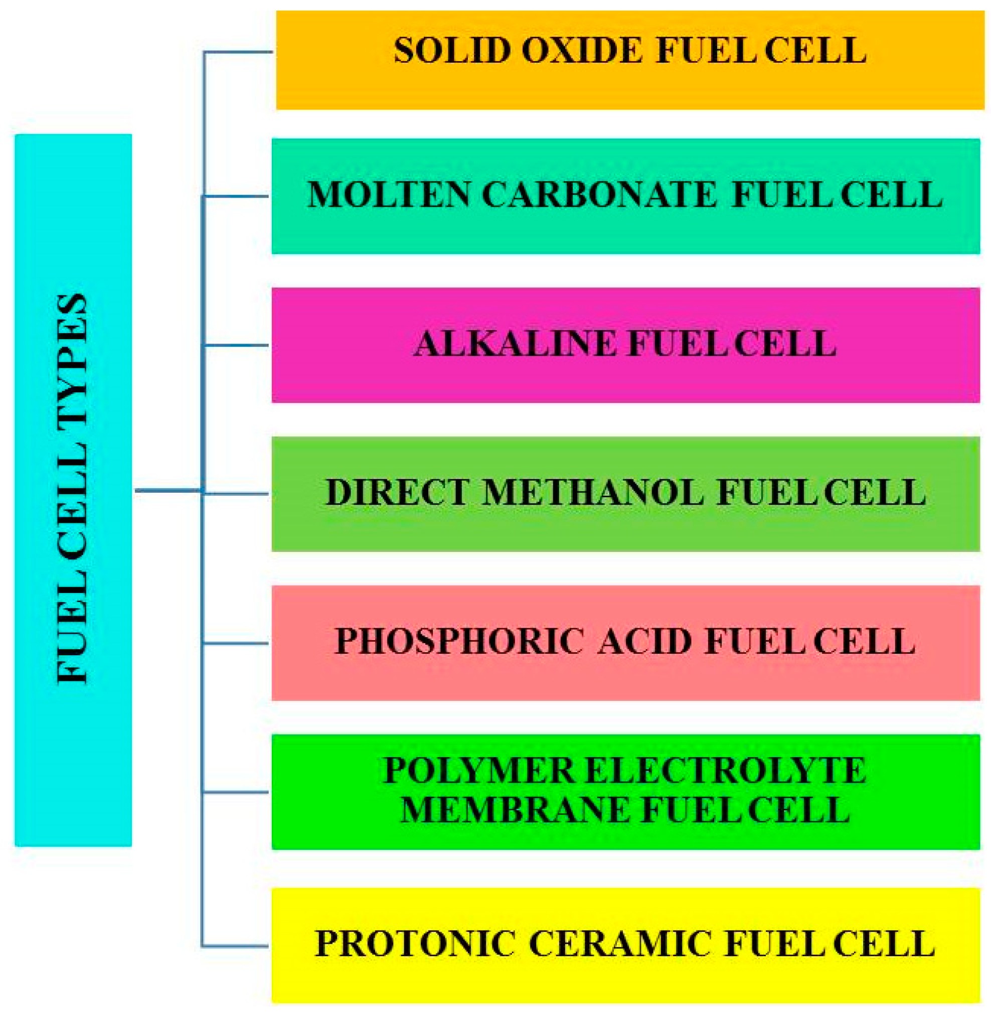
Figure 1. Classification of fuel cells.
Energies 16 00208 g001
Figure 2. Schematic representation of the working nature of a PCFC.
Energies 16 00208 g002
Figure 3. Properties of electrolytes.
Energies 16 00208 g003
Figure 4. The methodology used in CFD modeling.
Energies 16 00208 g004
Figure 5. (a) Structure of a typical fuel cell [54] reproduced with permission from reference [54], copyright 2009, Elsevier; (b) modeling of cathode side gas path of the designed stack; (c) three different types of stacks employed in 25 cell-PCFCs; (d) normalized flow rate distribution on PCFC piled stacks A, B, and C, reproduced from the reference [53], open access.
Energies 16 00208 g005
Figure 6. 3D model of (a) U-type, (b) Z-type air-flow channels used in 25-cell PCFC stacks, and (c) analysis of normalized air flow rate through these channels. Reproduced with permission from reference [39], copyright 2022, Springer.
Energies 16 00208 g006
Figure 7. (a) 3D and (b) 2D view of the inter-parallel flow field of a single cell; (c) three different rib channel groups employed the flow field. Reproduced with permission from reference [9] copyright 2022, Springer.
Energies 16 00208 g007
Figure 8. (a) 3D model of a 20 cells PCFC stack; (b) evaluation of flow distributions in 5, 10, and 20 cell PCFC stacks; (c) analysis of pressure drop vs. inlet manifolds width and (d) normalized flow rate versus cell numbers. Reproduced from the reference [37], open access.
Energies 16 00208 g008
Figure 9. (a) Rib channel and electrode of a single layer; (b) architecture for a planar proton ceramic fuel cell stack. Reproduced from the reference [55], open access.
Energies 16 00208 g009
Table 1. List of various types of fuel cells with electrolytes, including operating temperature, electrical efficiency, power range, advantages, disadvantages, and possible applications [42,43,44].
NoFuel CellElectrolyteOperating TemperatureElectrical EfficiencyQualified PowerAdvantagesDisadvantagesApplications
1Direct methanol fuel cell (DMFC)Polymer membrane (proton exchange membrane)60–200 °C20–30%100 kW–1 mWHigher power density, less operating temperature.Less efficiency, the byproduct is more toxic.Mobiles, laptops, and battery chargers.
2Alkaline fuel cell (AFC)Potassium hydroxide (aqueous alkaline solution)60–120 °C35–55%10–100 kWEfficiency is high.Requirement of high removal rate of CO2 from fuel and air.Aerospace and underwater environments applications.
3Phosphoric acid fuel cell (PAFC)H3PO4 (molten phosphoric acid)150–220 °C40%10 MWHigh efficiency,
the electrolyte is stable.
Power density is low, corrosion, less power, less current, and more weight.More energy is needed in hospitals, schools, and offices.
4Proton exchange membrane fuel cell (PEMFC)Nafion (polymer exchange membrane)50–100 °C35–45%100 W–500 kWPower density is high, less temperature, more safety, and the electrolytes are non-corrosive.The platinum catalyst is costly,
and low efficiency.
House, and vehicles.
5Molten carbonate fuel cell (MCFC)Sodium bicarbonate (alkaline carbonates solution)600–650 °C>50%100 MWEfficiency is high, ability to internally reform and fuel is flexible.Startup is slow, the electrolyte is corrosive, and managing the electrolyte is more complex.Large commercial distributed generation.
6Solid oxide fuel cell (SOFC)Yttria-stabilized zirconia (oxygen ion conducting ceramic oxide)700–1000 °C>50%100 MWEfficiency is high, flexible fuel produces waste heat, the electrolyte is solid, and it reduces management problems.Cost is high, startup is slow,
corrosion happens due to higher temperatures.
Factories, residential areas
7Protonic ceramic fuel cellProton conducting ceramic electrolyte450–750 °C
[45]
>50%
[46]
25 kW
[46]
High conductivity, working temperature is less compared to SOFCs, and lower degradation [20,47].Complex fabrication, Required suitable electrolyte and electrode materials.Remote power applications and heavy-duty trucking [48,49].
Table 2. List of the configuration employed in the recent models of PCFC stacks.
AnalysisConfigurationResultsRef.
CFDEnergies 16 00208 i001
  • Air-flow distribution in PCFCs can be improved only when the length of the MEA is increased to a sufficient limit, not by increasing its width.
  • To provide uniform air-flow distribution, the entrance and exit positions of the manifold play a critical role.
Zhu et al. [53]
CFDEnergies 16 00208 i002
  • The flow distribution on the PCFC stack is declined by increasing the cell number. At the same time, vapors are generated at the cathode side, which also reduces the uniform air-flow distribution.
  • Increasing the manifold radius may reduce the pressure drop in the PCFC stack.
Dai et al. [37]
CFDEnergies 16 00208 i003Rib channel design and inlet/outlet manifold play a key role to know the species distribution over the electrolyte surface.
Increasing the cathode layer thickness helps to provide better performance of the PCFC stack.
Dai et al.
[55]
CFDEnergies 16 00208 i004Inter-parallel structure manages the problem of pressure drop and removes water effectively.Akenteng et al. [9]
CFDEnergies 16 00208 i005The U-type air-flow path is the superior option for the PCFC stack to achieve higher air and oxygen distribution characteristics.Dai et al. [39]
Table 3. Different types of modeling analysis are carried out in SOFCs using various commercial software [63].
Different Types of Modeling and Analysis of SOFCs are Carried out Using Various Types of Software
CFD analysis (ANSYS)Electrochemistry and flow analysis are carried out using user-defined functions or add-on modules.
Hydrocarbon-fueled SOFCsHydrogen-fueled cells
Analysis based on the varying composition of fuels [64]Variation of fuel/air flow rates
[65,66]
Current distribution analysis [65,66]
Temperature distribution analysis [66,67]
Research-based on varying cross-section geometries of cells [68]
Impact of radiative heat transfer [69]Various flow pattern analysis [66,70]
Research-based on imposing thermal stresses on SOFC [71,72]Different thermal boundary conditions [71,73]
Flow analysis using ANSYS CFXBy varying manifold designs in SOFC [74,75,76].
Finite element method Analysis (ANSYS)Creep behavior analysis [77,78]
Torsion test in SOFC [79]
Crack initiation test [80]
Compression stress test [81,82]
FEM cum CFD Analysis (ANSYS)Used to analyze thermal stress on the stack [83,84]
MATLAB SimulinkThe partial pressures of hydrogen, oxygen, and water were calculated [62]
COMSOL MULTIPHYSICSThe effects of different gas flow patterns in SOFC were analyzed [61]
Electrochemical analysis on planar SOFCs [85]
Modeling of tubular SOFCs fed by biomass [86]
Modeling of hydrogen and coal gas-fueled flat-tubular solid oxide fuel cells [87]
Disclaimer/Publisher’s Note: The statements, opinions and data contained in all publications are solely those of the individual author(s) and contributor(s) and not of MDPI and/or the editor(s). MDPI and/or the editor(s) disclaim responsibility for any injury to people or property resulting from any ideas, methods, instructions or products referred to in the content.