Review

State-of-the-Art Research on Wireless Charging of Electric Vehicles Using Solar Energy

1
Department of Electrical Engineering, Amirkabir University of Technology (Tehran Polytechnic), Tehran 15875-4413, Iran
2
Department of Energy Engineering, Sharif University of Technology, Tehran 11365-11155, Iran
3
SDU Mechatronics (CIM), Department of Mechanical and Electrical Engineering, University of Southern Denmark, 6400 Sønderborg, Denmark
*
Author to whom correspondence should be addressed.
Energies 2023, 16(1), 282; https://doi.org/10.3390/en16010282
Submission received: 18 November 2022 / Revised: 5 December 2022 / Accepted: 13 December 2022 / Published: 27 December 2022

Abstract

:
Within the past decade, since impediments in nonrenewable fuel sources and the contamination they cause, utilizing green energies, such as those that are sun-oriented, in tandem with electric vehicles, is a developing slant. Coordinating electric vehicle (EV) charging stations with sun-powered boards (PV) reduces the burden of EV charging on the control framework. This paper presents a state-of-the-art literature review on remote control transmission frameworks for charging the batteries of electric vehicles utilizing sun-based boards as a source of power generation. The goal of this research is to advance knowledge in the wireless power transfer (WPT) framework and explore more about solar-powered electric vehicle charging stations. To do this, a variety of solar-powered electric vehicle charging station types are thoroughly studied. Following a study of many framework elements, the types of WPT components are explored in a different section. Within the wireless power transmission framework for solar-powered electric vehicle charging, compensators and various coil structures are also investigated, along with the advantages of each coil over the others. This study also discusses the use of artificial intelligence (AI) in WPT frameworks and highlights the important aspects of developing an AI model.

1. Introduction

Due to the growing demand of consumers worldwide, the need for electricity generation has increased [1]. At the same time, rising natural gas prices and regulatory emphasis on limiting greenhouse gas emissions have increased the cost of generating electricity using fossil fuels [2]. Because of this, there has been an increase in the usage of alternative energy sources for providing electricity, such as the solar power produced by solar systems. Utilizing EVs is another action to take to reduce air pollution. However, it needs to be taken into account that they only go a short distance on a single charge. Electric vehicles require charging stations for their batteries, as was previously mentioned. The most common and secure method of charging an electric vehicle is with a wire connected to the grid; however, the focus of this article is on the use of renewable energy sources, such as solar power, as a power generation source for wireless power transfer (WPT) technology. To avoid the drawbacks of using cables for charging, WPT can also be employed [3,4]. The structure of the charging stations, as well as their problems and potential solutions, are discussed in the following.
Figure 1 illustrates the general state of charge of an electric car wirelessly using a photovoltaic panel [2]. Solar cells and the controller section are two of the most crucial parts of the charging station. It is not feasible to obtain the maximum power from the solar panels at the output, due to weather conditions, shadows, the location of the sun according to the solar panel, and other variables. However, we can obtain and transmit the maximum power from the solar cells to the output by using maximum power point tracking (MPPT) algorithms.
The Perturb and Observation (P&O) method, which compares the voltage and current in every moment and the moment before and chooses the optimal value, is one of the most common and straightforward approaches in this subject. Another important component is converters, which can change the voltage level to the desired value. It falls into two broad groups, DC–DC and DC–AC converters, both of which are important. The best and most widely used converter is the buck/boost converter.
As previously mentioned, the losses that impact the system’s efficiency are the main problem with power transmission; hence, several resonates are utilized to create resonances, and the best of them is LCC resonance. Using various coil structures—which can be referred to as a circular structure, instead of the standard ones—is another technique to increase system efficiency, and after performing the above process, we can raise efficiency up to 90%. After transferring power to the secondary coil, an alternative voltage, that is, DC, is required. To accomplish this task, due to the high-frequency system, a high-frequency rectifier is required. Next, the voltage must be changed to a suitable voltage for the energy storage used in EVs. For EVs, lithium-ion (Li-ion) is frequently used, as it has a higher power density than lead-acid or nickel-cadmium rechargeable batteries. A DC–DC converter can be employed to do that. We can then wirelessly charge EVs using a solar panel after completing this method. Solar energy and electric cars may be utilized to minimize air pollution, which is a highly serious issue in recent years, owing to air pollution and the limited supply of fossil fuels [5]. Additionally, due to their limitations in storing energy and traveling short distances, electric vehicles need charging stations to be able to provide the energy required for electric vehicles to travel long distances. There are many ways to charge an electric vehicle, known as AC and DC charging modes [6]. Table 1 summarizes the types of charges available for electric vehicles. Since there are several sorts, each of which needs cables and unique converter heads to charge, technology has advanced to the point where it is now possible to transmit electricity wirelessly, as is covered below.
Here, the induction wireless power transmission mode—which has issues, such as power losses—is investigated for charging all-electric vehicles, in order to do away with various types of cables and unique converter heads. The properties of various resonants are holistically discussed in [4], and for gaining the maximum power output from the solar panel, MPPT is employed (one of the simple and efficient method is P&O [8]).
This article focuses on analyzing the methods and techniques required to wirelessly transmit power for electrical cars that use solar energy as a clean energy source. The objectives of the research are as follows:
  • The article begins with a discussion of photovoltaic systems, looking at grid-connected and off-grid options, and then looking at maximum power point tracking to maximize the amount of electricity generated by solar panels. This study also investigates energy storage to determine the best type of storage to save energy and minimize losses.
  • The study will explore several wireless power transmission techniques, including static and dynamic stations, to identify the distinctions and benefits of each station.
  • The paper will discuss coil structures to take into account the optimal and efficient structure for coils to prevent power loss, as well as to maintain safety due to magnetic waves, which are harmful to people. By reviewing these structures, the paper hopes to increase the efficiency and reliability of power transmission.
  • The evaluation of artificial intelligence applications used in WPT, whose primary objectives are to speed up computation, identify faults, and improve efficiency, is the last target of this article.
The architecture of the paper is organized as follows: Section 1 represents an introduction of wireless charging for electric vehicles utilizing solar cells. Section 2 discusses the fundamentals of the photovoltaic system and its components, as well as the various types of electric vehicles. The types of wireless power transmission, types of coil topologies, and their outcomes will all be covered in this section, as well. Section 3 will describe the use of artificial intelligence in WPT systems, along with the key factors that go into creating an AI model. We will review, wrap up, and make suggestions for further research in the fourth session. The final section will present the conclusion.

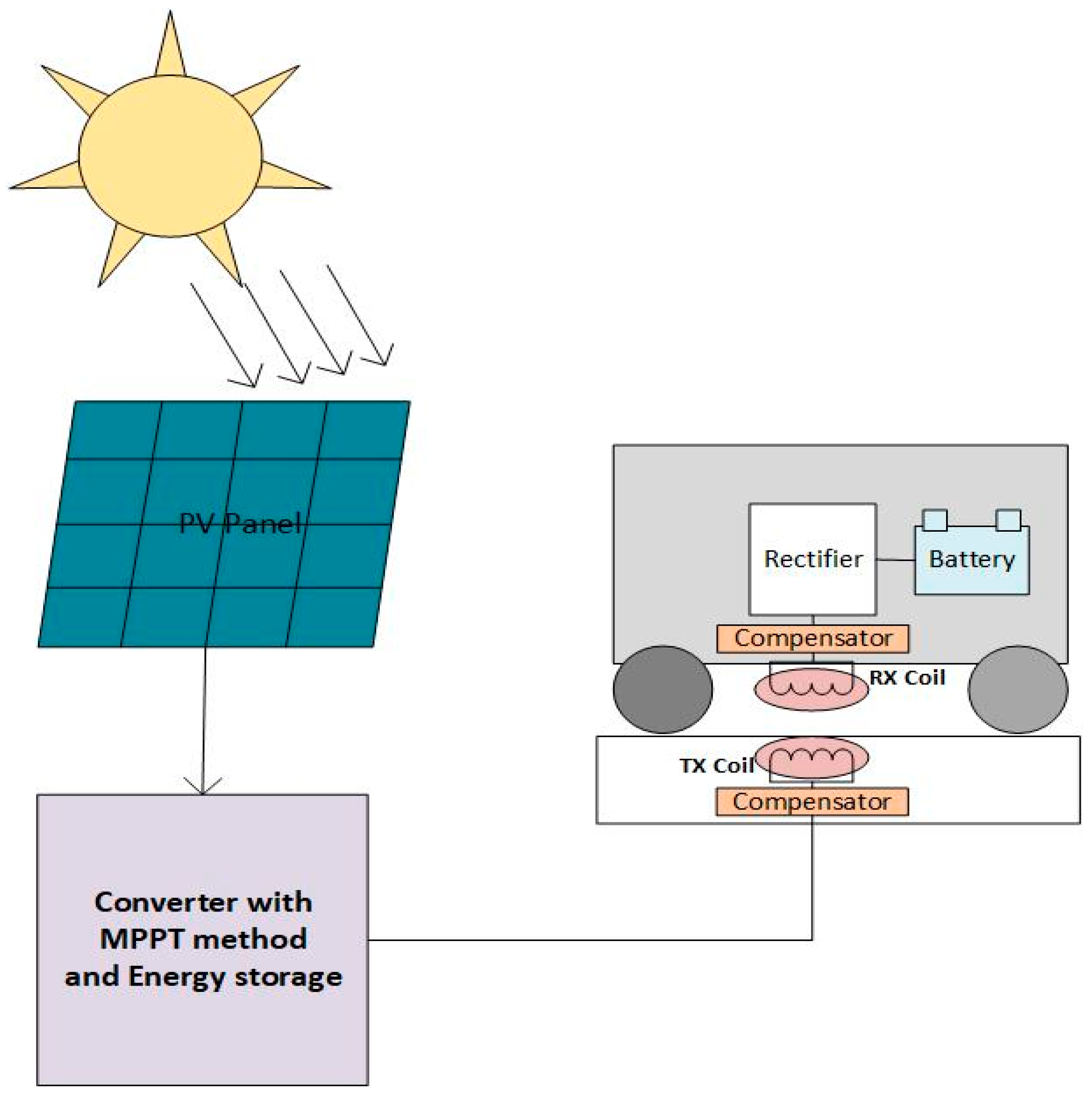
2. Wireless Charging Station for Electric Cars Using Solar Energy

In general, all types of charging stations will be divided into two distinct categories: static and dynamic. However, first, a look at solar systems is had before discussing different kinds of charging stations.

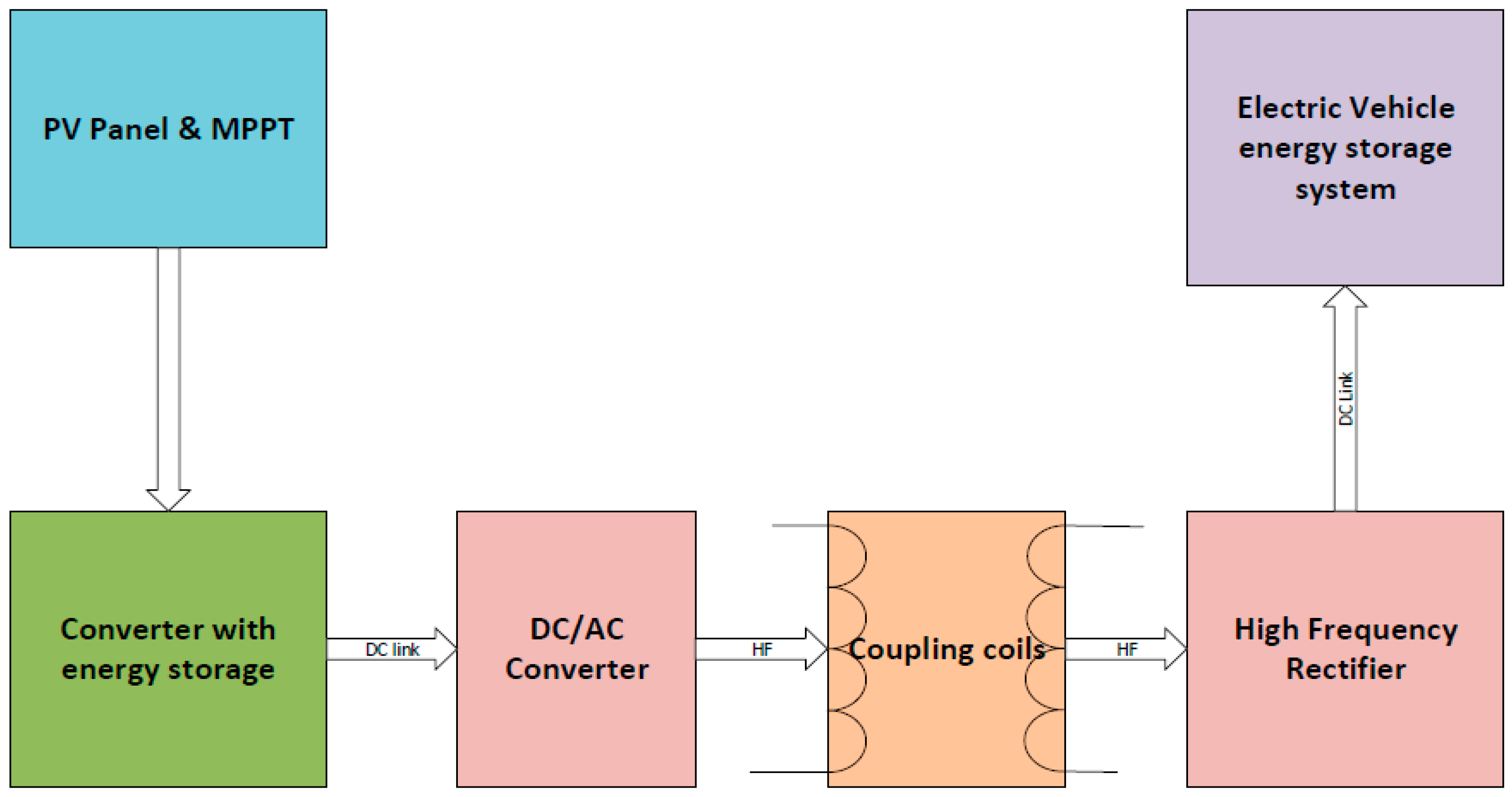
2.1. The Solar Power Generation System

According to Figure 2, a solar system has three primary components, and an energy storage system would make it four if we included it:
  • Photovoltaic array;
  • DC–DC converters;
  • MPPT system;
  • Energy storage system.

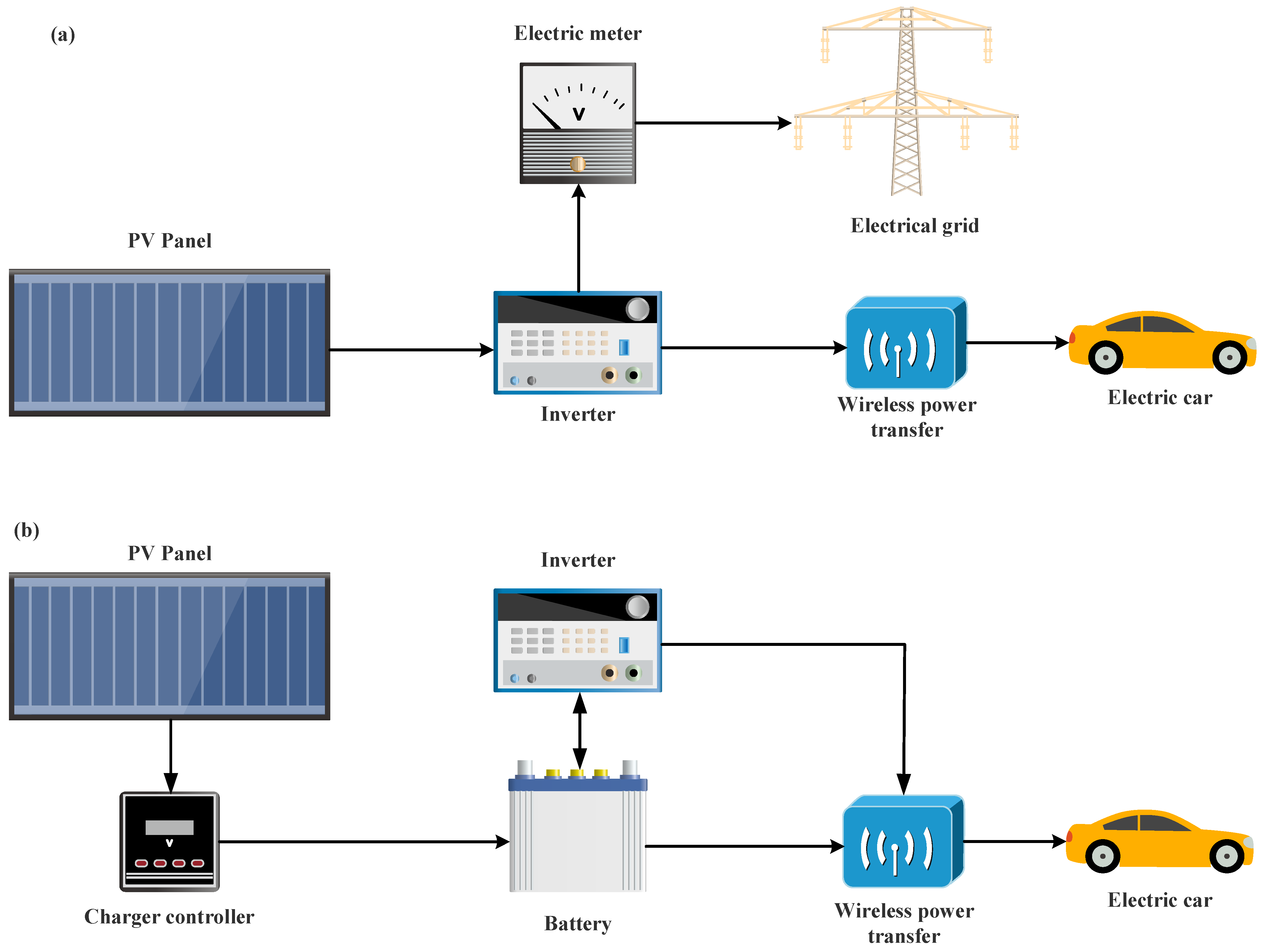
2.1.1. Photovoltaic Systems

The phenomenon by which the radiant energy of the sun is converted into electricity without the use of mechanical mechanisms is called the photovoltaic phenomenon. In general, photovoltaic systems are classified into two groups, according to their application: grid-connected units and off-grid units.

Photovoltaic Systems Connected to the Grid

In a grid-connected system, electricity generated from solar energy will be injected into the national grid. Photovoltaic systems connected to the national grid are centralized or decentralized to strengthen the national grid and prevent electrical pressure on power plants during the day, and more details about PV market could be found in [9]. The advantages of this system include easy installation and setup, high efficiency, and no need for complex peripherals. Figure 2a shows a grid-connected photovoltaic system. Typically, this system does not require a battery to store electrical energy, but sometimes, energy storage devices, such as batteries, are utilized to improve network reliability. Therefore, the grid-connected systems of global electricity can be classified into two groups, with a storage system and without a storage system [10].

Grid-Independent Photovoltaic System

The off-grid system is illustrated in Figure 2b. In unfavorable weather conditions, it is necessary (or required) for the energy storage system to be able to feed the entire load of the system for several days. These devices are typically utilized in places where there is no access to the national power grid or where it is expensive to connect. For example, in mountainous telecommunication bases, nomadic areas, rural cottages, and to meet the electrical needs of areas that do not have a national electricity grid in general, a grid-independent photovoltaic system can be used [11]. The conceptual foundation and environmental impact of PV systems are covered in further depth in [12,13].

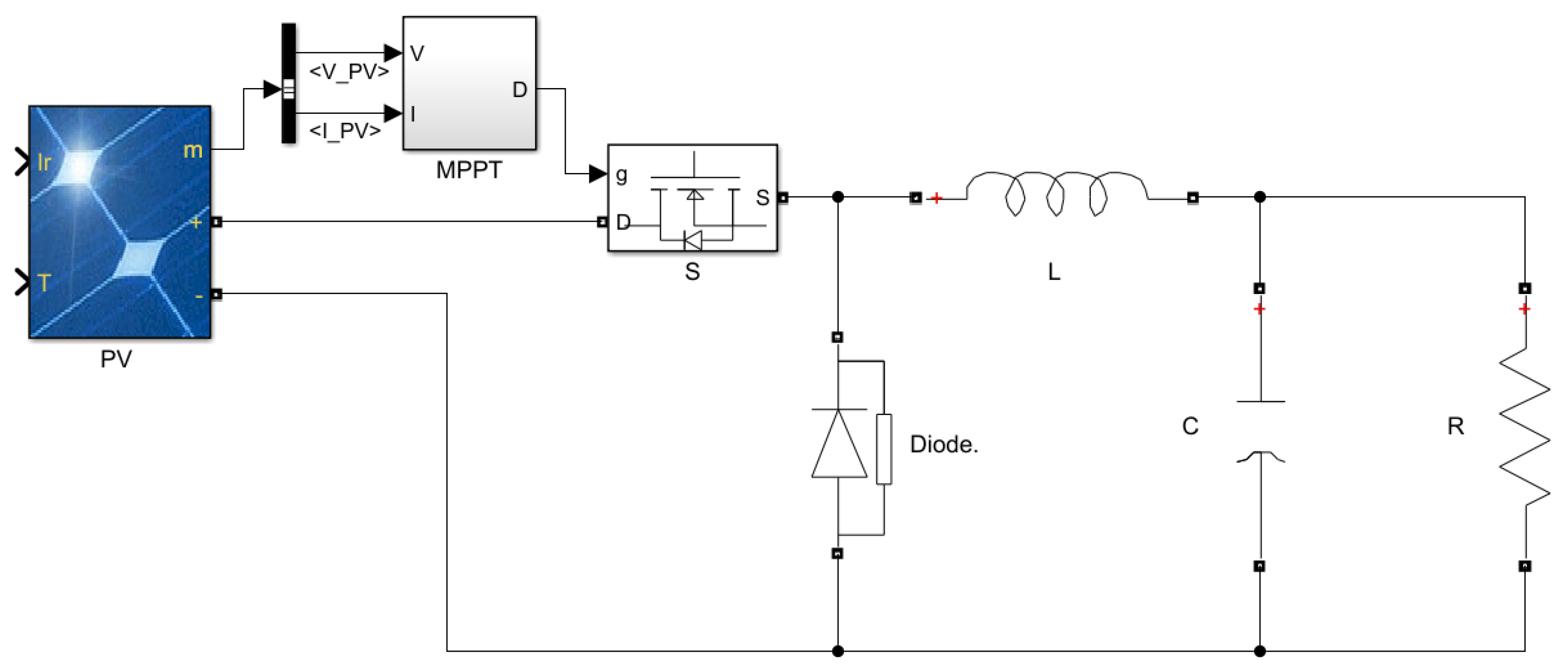
2.1.2. DC–DC Converter

Converters play a major role in the photovoltaic system, which is responsible for changing the voltage and current to the expected value. DC–DC converters can be divided into two types of reducers and boosters [14]. The aid commands the switches to turn on and off, and the circuit operates to reach the expected voltage level. Figure 3 represents the electrical circuit of the buck converter:
As mentioned in Figure 3, the circuit has a duty cycle that is obtained from the following equation:
D = T o n T o f f = V O V i n
in which T o n is the time for the switch to be on, T o f f is the time for the switch to be off, V O is the output voltage, and V i n is the input voltage.

2.1.3. Maximum Power Point Tracking Methods

The non-linearity of the solar cell output characteristic, as well as the fluctuation of light radiation and even cell temperature, are some of the problems that hinder solar panels from operating at their maximum power point. As a result, a system for controlling solar cells must be taken into consideration. This system should not only position the solar cell at its best working point, but should also be able to continuously track the maximum point of the system’s maximum transmission power in the event that this point changes due to the weather conditions and position the solar cell there. This type of continuous following is called the maximum transmission power. The task of the MPPT algorithm is to find the actual maximum power point and track it. It should be noted that, in some cases, especially in conditions of non-uniform radiation, several local maximum points may occur; but there is only one real maximum point. Different ways have been suggested to pursue maximum power [15]. There are two types of algorithms for MPPT, including conventional and intelligent. One of the most widely used conventional methods that has been considered in this research is the perturbation and observation method, and one of the intelligent algorithms of MPPT is fussy logic [16].

Perturbation and Observation Method (P&O)

The basis of this algorithm is to create a disturbance in the operating cycle of the electronic converter of power and consideration and its effect on the output voltage of the array (PV) (Figure 4). Disturbance in the power cycle of the electronic power converter will lead to disturbance in the current of the PV array and, consequently, the disturbance of the voltage of the solar array.
If we are on the left side of the MPPT, increasing the voltage causes an increase in power, and vice versa, if we are on the right side, increasing the voltage causes a decrease in power (Table 2).
According to the table, and according to this algorithm, if an increase in power is observed, the perturbation should stick in this path to reach MPP, and if the power falls, the perturbation should be in the opposite direction. This process should be repeated over and over until we reach MPP [18]. One of the problems with the P&O algorithm is that it does not perform well in the face of rapid climate change. This is shown in Figure 5. In constant weather conditions, changes A in PV voltage, move the working point to B, and due to the fall in power, the disturbance signal is reversed. In this case, the radiation level is increased, and the curve is transferred from P1 to P2 in the same time interval. The working point is shifted from A to C, an increase in power is observed, and the perturbation continues in this direction. Therefore, the working point moves far away from the MPP point, and if the radiation level increases, the algorithm diverges [19].
However, the P&O algorithm to extract the maximum output power of the solar panel might be a significant and effective method, among the numerous methods of maximum power tracking, due to its simple algorithm, high reliability, and quick tracking [20]. For a better understanding of the P&O method, the flowchart of this method is shown in Figure 6.

Fussy Logic (FL)

Using FL for MPPT prepares several benefits. A number of them are to track the MPP with high precision, not be influenced by disruption of the inputs, and work independently and unpredictably [21,22]. The FL algorithm includes three steps. In the first step, fuzzification, numerical data are converted into linguistic values with the help of the membership function. There are five levels: Z (zero), NS (negative small), PS (positive small), NB (negative big), and PB (positive big) [23]. The FL method inputs generally contain functions that express the error (E) and change in error (ΔE); questions are given below:
E = P p v ( t ) P p v   ( t 1 ) V v p ( t ) V v p ( t 1 )
Δ E ( t ) = E ( t ) E ( t 1 )
where P p v is the output power of the PV panel, V v p is the voltage of the photovoltaic panel, E is the error, Δ E is the error difference, and t is time.
In the second step, the rule table, inputs are processed and a decision is made. In the last stage, defuzzification, linguistic data is converted to clear data [24].

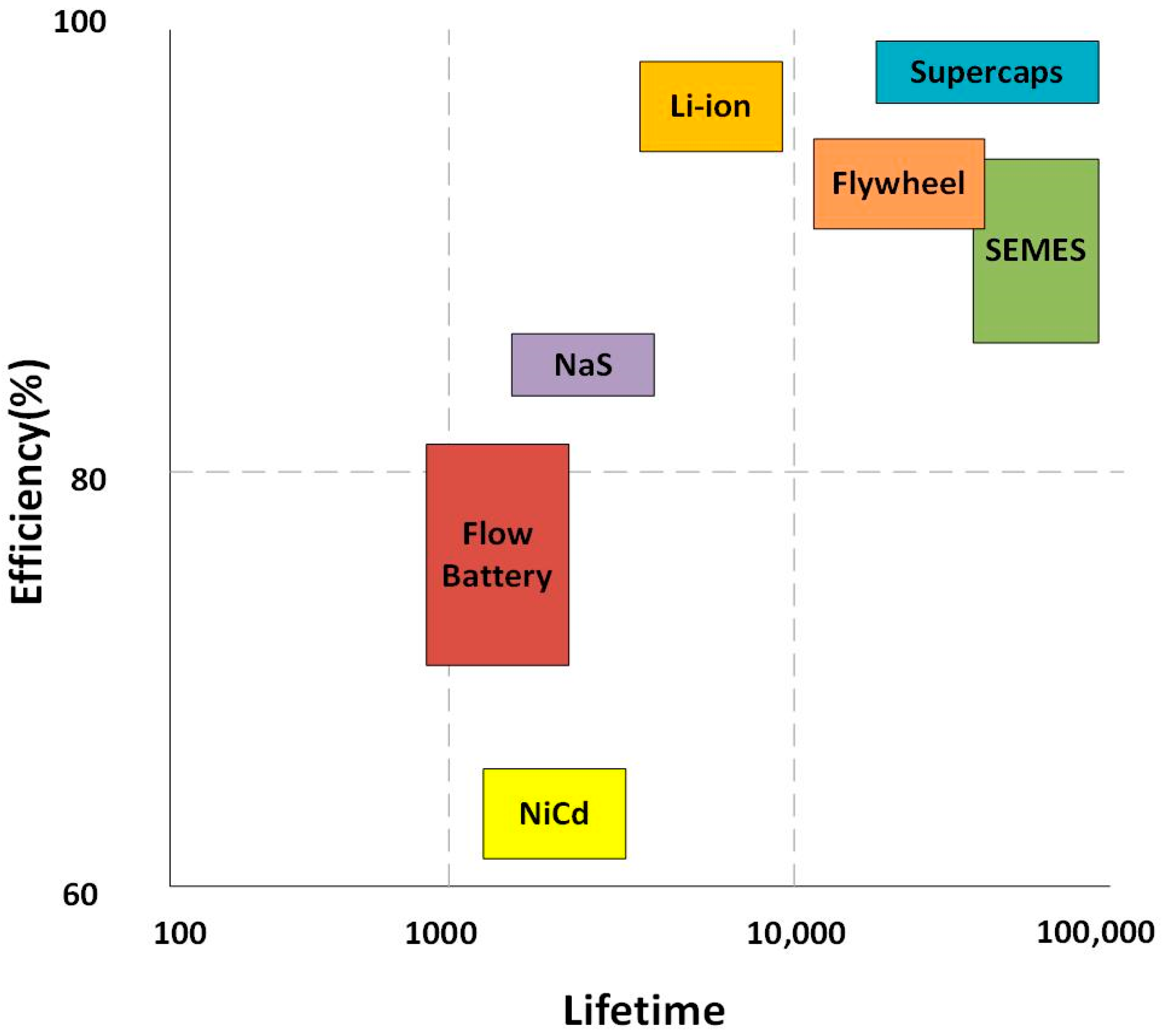
2.1.4. Energy Storage

Storages may be utilized as a component of a photovoltaic system to supplement solar energy during times of low solar output or at night. Storages are also used as batteries in electric vehicles to power the car. There are different types of storage devices, which we see in Figure 7, comparing the life and efficiency of storage devices [25].
As can be seen, the best types of energy storage are lithium-ion batteries and supercapacitors, which have been used recently in [26] and [27]. Lithium-ion batteries, as one of the storage unit types, are usually employed in electric vehicles as energy storage and power supply, which have advantages such as low volume, high durability, and good efficiency.

2.2. Wireless Electric Vehicle Charging Systems

2.2.1. Static

The static wireless electric vehicle charging systems (WEVCS) initial arrangement is represented in Figure 8. Additional power converters and circuits are installed together with the primary winding beneath a road. Typically, the secondary coil or receiving coil is positioned underneath the EVs, either in the front, back, or center. The received electricity is converted from AC to DC using a high-frequency rectifier and transferred to the battery bank. Due to some safety issues, the controller and battery management systems are employed to get feedback from the system. The amount of power coming from the source, the size of the charging pad, and the space between the two coils all affect how long it takes to charge. We can install static-WEVCS in parking’s, garages, homes, commercial buildings, and shopping centers, with an average distance of around 150 to 300 mm between light electric vehicles [28,29,30,31]. This kind of wireless charging station is seen in Figure 8; a solar power plant has been set up nearby that uses MPPT technology to boost power output. Because the energy generated by solar panels is DC, it must be converted to AC for wireless power transmission. A converter is needed to change the system’s electricity from DC to AC, so that the car can be charged. The output of this converter is given to a compensator to increase efficiency. Another compensator is placed in the receiver coil. A compensator is employed to minimize the phase between the voltage and current, as well as to minimize the reactive power in the system [4,32]. In fact, a compensator is needed to increase the efficiency and useful transmission power [33]. In addition, a rectifier converter is placed to convert AC to DC electricity to charge the electric vehicle battery (recent developments with rectifiers can be found in [33]).

2.2.2. Dynamic

Plug-in or battery electric vehicles (BEVs) suffer from two major problems—cost and range. To increase the range of distance with fully charged electric vehicles, they must be charged continuously or often need to install a larger storage unit (which leads to additional problems such as cost and weight). Additionally, a common charging method for EVs is not cost-efficient; so, for the problem, we can use a dynamic wireless charging system for electric vehicles (D-WEVCS), which is known as an “electric road”. Research shows that this method can reduce the problem range and cost of electric vehicles. Primary coils are positioned and spaced in the road with a high voltage, high frequency AC source, and compensation circuits to the microgrid and/or renewable energy system (RES). The secondary coil similar to static-WEVCS is located below the car and is used to receive the magnetic field generated when electric vehicles (EVs) pass the transmitter. Then, the magnetic field is converted to the DC charge by the power converter BMS. The Possibility of frequent charging of electric vehicles reduces the storage unit size; the need is almost 20%, compared to the current EVs [32]. The dynamic wireless charging station system is similar to the static one, with the difference being that the number of transmitter coils is usually more than in the static mode. Therefore, all of the static charging station system’s stages apply to the dynamic station, as well. A dynamic wireless charging station for electric cars using solar panels is shown in Figure 9.

2.3. Electric Vehicle Connection Type to Grid Models

Electric vehicles can be divided into different modes when connected to the charging network, as follows:
Grid to vehicle connection mode (G2V);
Vehicle to grid connection mode (V2G).
With the increase of electric vehicles and their battery, we need to charge them, and because of that, the extra load is added to the distribution network. The distribution network will suffer if this load imposition happens during peak hours, leading to higher losses and voltage decreases [34]. Additionally, by developing smart grids with online control, the two-way power exchange capability of electric vehicles, and especially the V2G discharge capability of vehicles, can be used. G2V is also used when solar energy is low and the number of cars to charge is high [35], as shown in Figure 10.

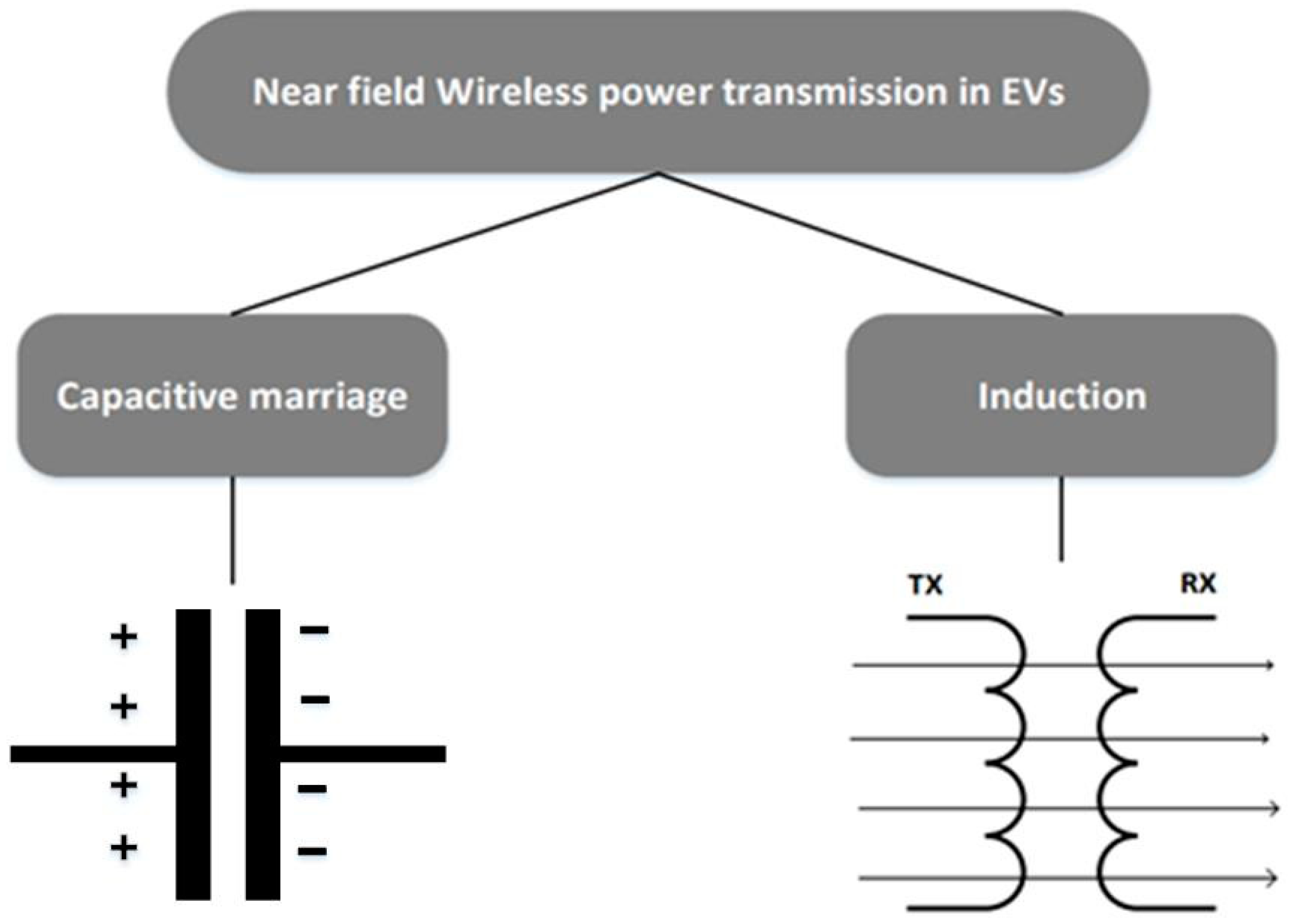
2.4. Wireless Power Transmission

Wireless power transmission (WPT) is used for this purpose. Here, we examined different coil structures, such as circular structure and DD, as well as DDQ, which are proposed by researchers at Auckland University [35], in which the DDQ structure has shown better performance than other structures. We also list the compensators and compare them to determine which one is the best; the SS compensator performed well, while simplicity was taken into consideration. There are different ways to transmit wireless power, which can be transmitted by radio waves or electromagnetic waves. The focus on electromagnetic waves for wireless power transfer changed as electromagnetism science developed and radio waves were found to be feeble.
Later, with the advancement of science in the field of power transmission, they tried to reduce the dimensions and safety more. They also tried to reduce losses at short distances. Resonance induction is the most popular method for wireless power transmission at short distances nowadays. It was developed by MIT University in 2007 and was designed to enhance the effective distance of power transmission and increase efficiency [36]. As of now, their thoughts are focused on minimizing power losses and boosting the transmission power under consideration.
British scientist Michael Faraday contributed to advance the electromagnetic field by creating Faraday’s law of induction. This rule outlines the process through which electromagnetic induction or EMFs are produced. The so-called electromagnetic force voltage (Vemf), as stated in Equation (4), is created by varying the flux by the temporal change multiplied by the quantity of windings in the coil.
V e m f = N d φ m d t
where N is the number of turns of the coil, and m is the change in magnetic flux [37]. Wireless power transmission has different types that can be divided as follows, which is shown in Figure 11 [38]:
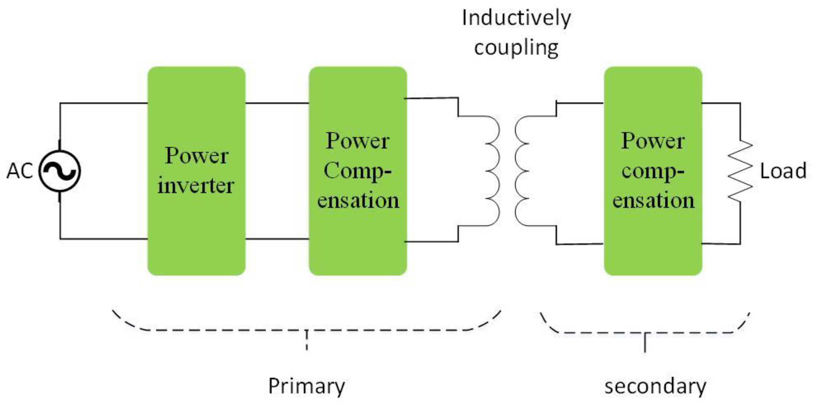
Induction wireless power transmission;
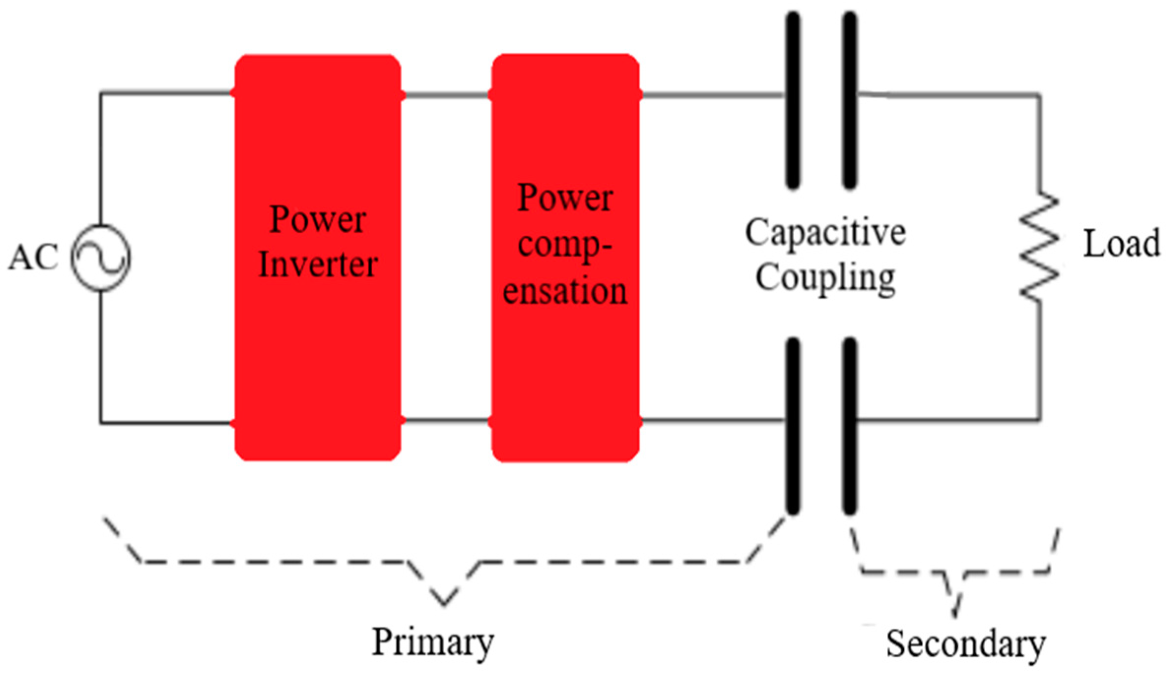
Capacitive coupling wireless power transmission.
This study focuses on power transmission at close distances.
  • Induction wireless power transmission mode.
Induction Power Transfers (IPTs) are commonly used to transmit power wirelessly, and they have problems. Problems of this type of induced wireless power transmission can be called eddy current losses. The advantages of this type of transmission include safe power transfer on a rainy day, long life, and high reliability [39]. Figure 12 depicts a schematic of induction WPT.
2.
Capacitive coupling wireless power transmission mode.
This model’s field coupling, also known as capacitive power transfer (CPT), offers some advantages. This method overcomes the restriction that magnetic energy cannot pass through a metal shield or plate and achieves this while also reducing energy losses, keeping magnetic field interference at a reasonable level, and avoiding field interference. It makes the system operate in a saturated state, a strong magnetic field, and also when there is an electric field present [39]. However, this mode of power transmission can be very dangerous for humans, due to the sudden discharge of high voltage of this type of power transmission. We see an example of this in Figure 13.
Additionally, for the long-distance power transmission mode, we will only discuss the microwave mode, which is more useful in the field of telecommunications. This type of power transmission is performed using high-power antennas, which can be seen in Figure 14.

2.4.1. Important Factors in Wireless Power Transmission
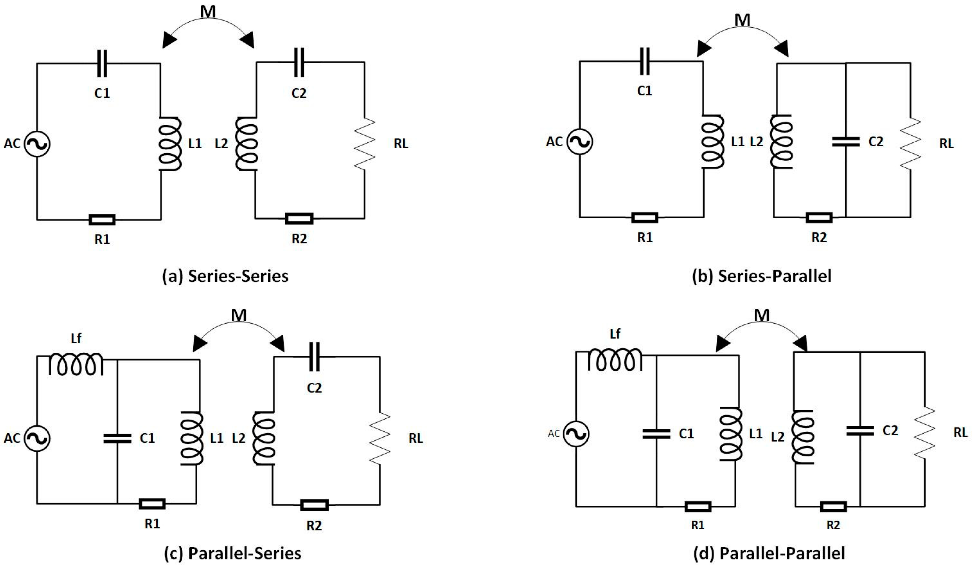
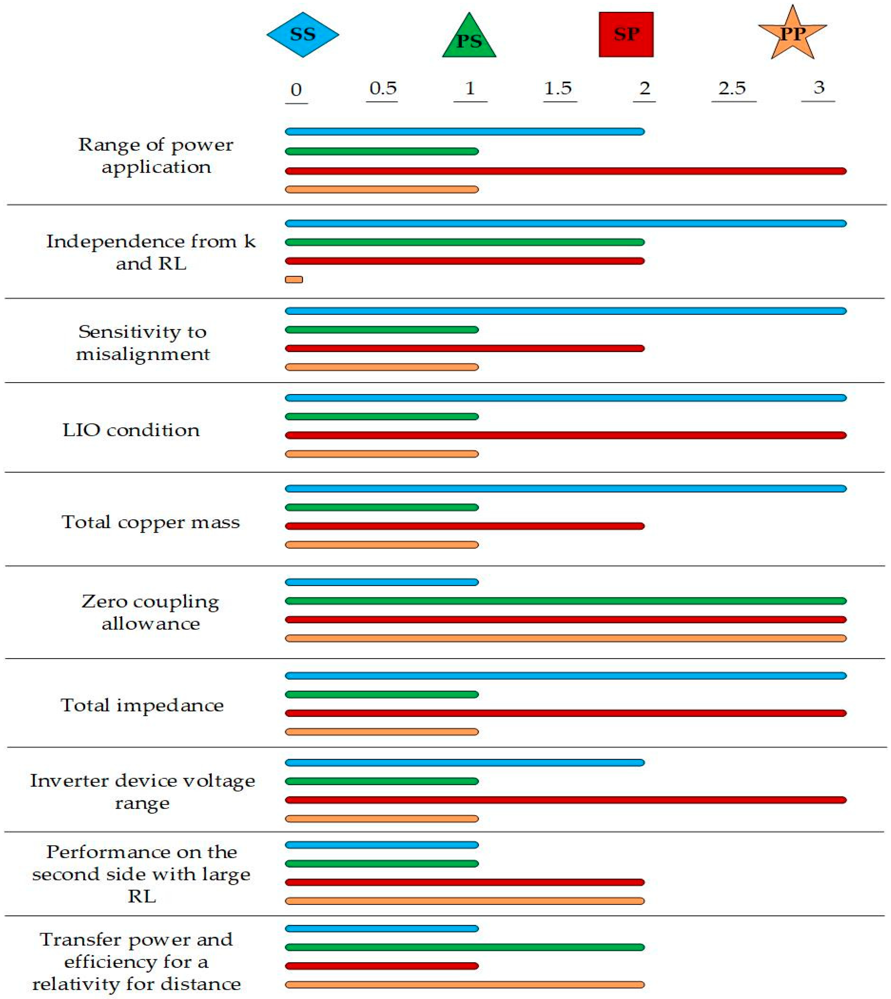
The resonators used should be as light as possible and have low sensitivity to displacement. In addition, these resonators should be able to operate at an average air distance of about (10–20 cm). One of the suitable methods for increasing the efficiency is the coupling coefficient and the quality coefficient, which is possible with the proper design of the complex structure of the resonator (wires). To achieve high efficiency, the coupling coefficient k and the quality coefficient Q must be large. In general, the coupling coefficient increases as the air gap increases. If the increase in efficiency is achieved by increasing the power, it cannot be a good method. In the resonance induction method, the magnetic coupling coefficient between the coils, due to the relatively large air gap, compared to the non-resonance induction method, is generally about 0.1 to 0.5, which is about 0.95 for the non-resonance induction method, which has a similar function to transformers. Increasing the quality coefficient increases the efficiency and the smaller the coupling coefficient, the higher the quality coefficient will affect increasing the efficiency [40]. The coupling coefficient (k) can be obtained from the following equation, which is usually between 0.1 and 0.5:
K = M L 1 L 2   0.1   <   K   <   0.5
K : coupling coefficient;
M: mutual inductance;
L 1 :   primary   coil   inductance ;
L 2 :   sec ondary   coil   inductance .
Additionally, the quality factor Q is usually between 10 and 1000, and numbers below 10 are not acceptable, which is obtained from the following equation:
Q = ω L R 10   <   Q   <   1000
Q :   quality   factor ;
ω = 2 π f ;
L: inductance of the coil;
R: resistor of coil.
Additionally, other issues, such as magnetic field interference and safety [41], are addressed by measures in the structure of coils.

2.4.2. Compensator

In a wireless power transmission system with resonant coupling, it is essential for employing a compensation network to lower the VA rate of the coil and power supply due to the weak coupling and substantial leakage inductance of the coils [42]. The use of capacitors on both the transmitter and receiver sides is the simplest way of addressing inductance leakage. Depending on how the capacitor is placed in the circuit, four types of compensation are possible. For this purpose, they were introduced as series–series (SS), series–parallel (SP), parallel–series (PS), and parallel–parallel (PP), based on configuration [43]. These structures are used to compensate for leaks from the induction coil, which is called a compensator [14]. The basic topologies are shown in Figure 15.
The correlations in Table 3 can be used to compute the values of capacitors based on the layouts of the aforementioned topologies, as shown below [44]:
Now, according to the above explanations and the introduction of compensators, a general comparison of compensators in wireless power transmission is given according to the criteria of coupling coefficient values and winding weight, misalignment, and voltage value, etc., as shown in Figure 16 [45].
In light of the comparison in the above figure, the SS structure, which was the simplest and very well topology at the time it was developed and is still in use, is our next choice. As can be observed, this structure has a strong coupling coefficient, but a lot of copper was used in its construction, and it also has a high impedance and poor efficiency with distance.

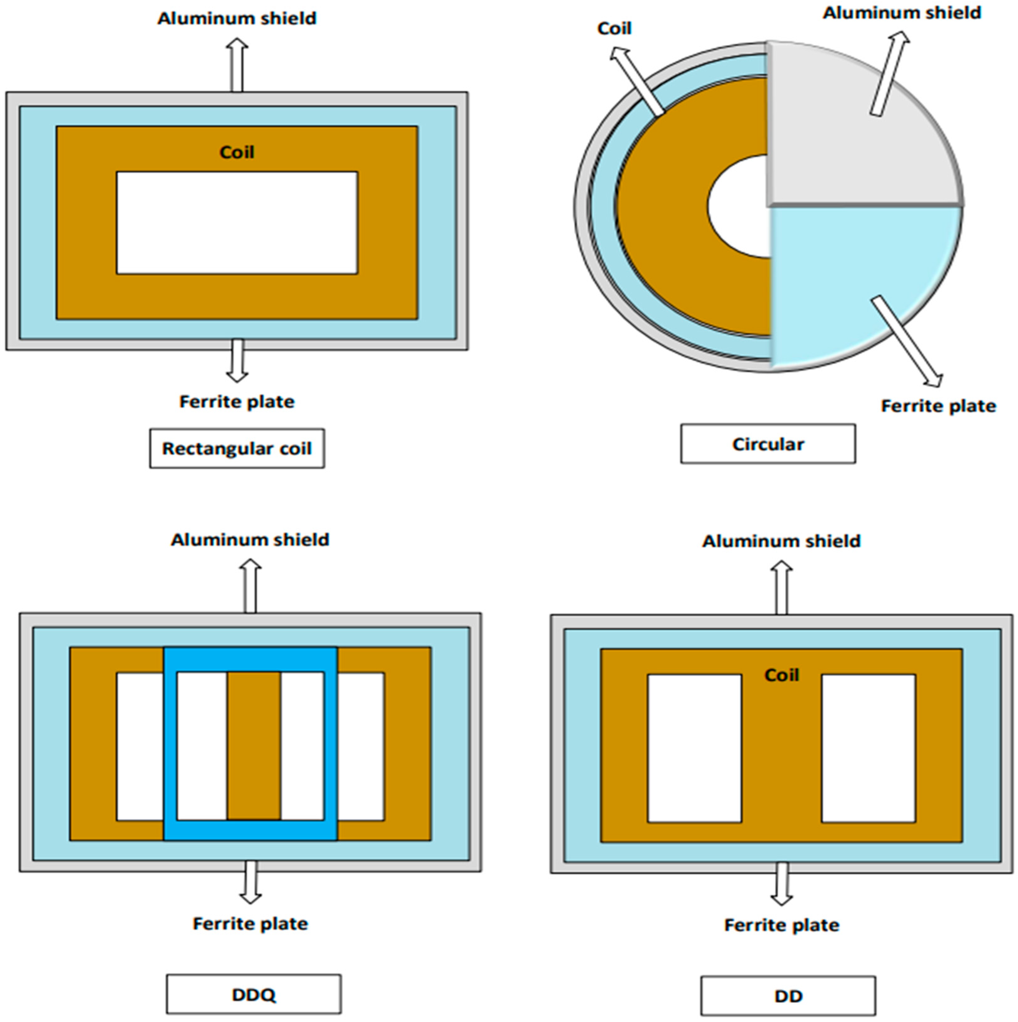
2.4.3. Coil Structure

As we saw in the previous section, efficiency and safety are important factors in the transfer of wireless power. Among the many ways to improve the two factors we discussed is to change the coil’s structure. The information below belongs to the primary coil’s construction (Figure 17):
Circular structure;
Rectangular structure;
DD structure;
DDQ structure.
Other structures are also seen in [46]. The DDQ structure is the most effective coil structure, as determined by prior research and outcomes. In the next section, we discuss coil structure. The coil construction in Kim’s research project [47], which depicted a simple circular shape and employed three ferrites’ cores in parallel and an aluminum shield to lessen radiation and promote safety. According to Ongayo and Hanif’s [48] research, the new improved circular structure was suggested, while taking into account the electromagnetic interference (EMI) and electromagnetic field (EMF) effect. As a result, the ferrite core was used to improve the flux path and reduce losses and leakage. However, these plates are typically expensive and delicate, in comparison to their structures. Aluminum shielding is used to reduce magnetic radiation that is harmful to the human body and reduce leakage current. It causes and transmits little power and has a short air distance. The coupling coefficient and efficiency have grown, but on the other hand, the price and weight have gone up. It also transfers a little amount of power in a small air gap.
Table 4 illustrates the results of the simulation, where D is the distance between the transmitting and receiving coils, L1 and L2 are the primary and secondary coil self-inductances, respectively, M is the mutual inductance, and k is the coefficient of coupling. The results make it clear that the L1 and L2 variations, when d changes, are much smaller than the M variance. In each of the three possibilities, M and k increase as the separation between the two coils decreases. More power is delivered to the output when M and k are bigger. In comparison to the coreless transfer, the values of M and k will rise if a ferrite core is used. A coreless transformer will be light and inexpensive, but it cannot be used for high and efficient power transfer, due to its low coupling factor and mutual inductance. A comparison of shielded and unshielded transformers reveals that the parameters, particularly M and k, change little. As a result of shielding, M and k are only slightly reduced.
In a research study [49], Mohammad and Choi showed that the DD structure was improved over the circle structure, but the alignment sensitivity was increased. Their results showed that the rough core surface has many core losses. The suggested structure with optimal thickness and smooth structure significantly reduces the core loss. In the optimized core, the losses are reduced up to 60%. The maximum permissible core losses for a specific system are determined by considering the coupling factor and the quality factor for uniform thickness and the suggested optimal core. In [50], the DDQ structure was proposed by Mirslim and Rasakh, and compared to the DD structure, the sensitivity to alignment decreased. Their research used two structures, the DDQ structure was located on the receiver or secondary side with a square coil, and the receiver side used a LLC compensator that increases the X-axis tolerance, which made the system more compact, and also efficiency increased, compared to the DD structure. Other structures, such as the bipolar pad structure used in [51], developed by Mirsalim and Rasekh, for the bipolar structure, which was obtained from two D-pads that were overlapping, and in this paper, using a LCC compensator, using LCC increases the efficiency and improves the lateral (horizontal) misalignment and reduces the size of the transmission plate and examines the effect of coils on each other. In [52], they chose the tripolar pad (TP) structure from three coils, and in this article, we used an SS compensator structure. At first, the value of the capacitor is determined in such a way that it removes the imaginary parts of the impedance that can be seen in the output. In this method, the inductive load can keep the compensation and the resonant frequency constant by comparing the two scenarios, and the suitable value for the capacitor can keep the nominal voltage constant in the non-alignment position. As it was said, for the back of the pads, a flat aluminum plate is used to protect and bind the radiation of the electromagnetic field, and ferrite magnet is used to improve the magnetic field, which is an expensive metal. This structure is proposed to reduce the cost and improve efficiency. Table 5 reviews some recent articles on WPT.

3. Application of Artificial Intelligence in WPT

There are several studies on the WPT system that focus on the goal of achieving higher distance transmission. The research has mainly focused on impedance adaptation and the design of resonators [61,62,63], transducers, and power electronics and inverters with appropriate control methods [64]. According to the needed performance, which varies depending on the application, WPT systems were constructed. They can be used in many different ways; for example, small coils can be useful in biomedical applications, while medium-sized coils are suitable for wireless charging, and larger coils are made for charging electric vehicles. The types and dimensions of the winding affect the power transmission efficiency and lead to other various changes in different parameters, such as mutual inductance, resonance frequency, and so on [63]. Trial and error exercises are time-consuming when calculating parameters, and the outcome may not be altered from a theoretical, simulation-based, or computational standpoint.
WPT and ANN approaches are offered as a way to cut down on this enormous amount of time. An illustration of soft computing is artificial neural networks (ANN), which can handle complicated IT equations and numerous parameter calculations. It is used to identify unidentified parameters and computational methods that simulate an accurate answer quickly. For instance, a WPT design with a high transmission efficiency can be adjusted based on the coil design, inverters, and the volt-ampere (VA) ratings of the active and reactive elements. There is an issue which is related to a huge computational load due to the training all of the combinations of parameters and variables. The WPT design and optimization techniques nowadays can result in a speedier convergence. It is possible to generate reliable outcomes using a variety of soft computing techniques (grouped based on fuzzy, evolutionary logic algorithms, and ANNs) [65,66,67]. ANNs are analogous to a sophisticated processor with a shared aim to preserve useful data and make it accessible for additional usage. ANN functions in two stages. The initial stage is to gather information about a network across the teaching and learning process. Second, weights are the terms used to describe how neurons are connected. The output of neurons is determined by how well the consequences perform. A bigger impact on the output is provided by a connection with more weight. When tackling problems with complicated nonlinearities, neural networks are known as generic estimators, and educational algorithms are a crucial component of neural networks. A primary neural network consists of three types of layers, as seen in Figure 18 [68].
The third layer is the output layer, whereas layers beginning with input layers are connected by certain hidden layers. Different types of neural networks are recognized based on the interactions between layers, and the connection weight minimizes the error between the neural network’s acquired and desired outputs. Synaptic connections link the three layers together to train the neural network. As a consequence, an algorithm is appropriate based on the problem for which a resolution is required for the best and most accurate outcome possible. Artificial neural networks are used in numerous applications because of their versatility in a variety of tasks, including adaptive control, system identification, function approximation, and optimization. Researching and finding solutions are other advantages of using ANN techniques. Adopting ANN techniques saves time and money actions, thereby minimizing processing requirements simply by shortening the time spent using the device. Its ability to handle imprecise data and non-linear mapping guarantees its acceptance as part of the simulation. The most popular and fundamental ANN technique is known as regression propagation (BP), also known as error return, and it has been utilized as a method for optimization in many different sectors for a variety of applications. The error correlation learning rule serves as the foundation for BP propagation, which has at least three interconnected layers. The first layer’s output serves as the operation’s starting point, and from there, the connection procedure is repeated until the final receipt. Particle swarm optimization (PSO) and genetic algorithms (GA) are two more common methods employed because they are simpler than BP. A crowd-based community behavior called ethics serves as the inspiration for the stochastic approach known as PSO. PSO and GA are virtually the same in that they loop through a generation hunting group in search of the best outcome with a random population. However, evolutionary operations, including crossover and mutation, are not incorporated in the PSO algorithm [69,70]. Instead, particles fly in search of the problem area the optimal result follows the current optimality particles.
In WPT, several BP, GA, and PSO optimization and modification techniques are used. They enhance: (A) The coil design; (B) frequency division and consistency; (C) power transfer efficiency (PTE); (D) energy management; (E) converter (power electronics), and fault analysis. In WPT, optimization using ANN is primarily concentrated on enhancing PTE, and validation of ANN is typically accomplished by contrasting the findings of ANN by employing software for finite element analysis (FEM). MATLAB or ANSYS Maxwell HFSS are used. It is challenging to forecast each value, since there are many variables that affect the process of creating a steady output, including the primary coil, current, and location of the transmitter and receiver coils at the time of the reception unit and route. The output current and parameter changes might be kept constant to account for undetected BP disorders. The PID controller receives the BP train, and MATLAB/Simulink are often used to model the system [70]. Some articles on the use of artificial intelligence in WPT have been reviewed in Table 6.

4. Recommendations and Future Work

Today, due to the growth of using electric vehicles, the need for charging EV stations has increased, in which one of the sources that can be used in charging stations is a photovoltaic system, and we also discussed that the best method for charging electric vehicles is wireless method, which can be improved by using the following suggestions:
(1)
Using wireless charging during vehicle movement, which will reduce the cost of energy storage units.
(2)
Improving wireless power transmission by using new coil structures and using new resonances suitable for improving power transmission.
(3)
Applying the new MPPT algorithm or combine several algorithms to improve solar panel output energy.
(4)
Using new converters or a combination of existing converters that can be used for this type of system.
(5)
Creating a wireless charger that can quickly charge a vehicle, compared to the time it takes to do so using a plug-in charger.
(6)
More consideration and study must be given to enhancing shielding, in order to promote health and safety.
(7)
Implementing reinforcement learning and deep learning algorithms to reduce misalignment errors.
(8)
Employing quantum computing methods for better power transmission with more precision and speed.
(9)
We need to find innovative methods to reduce the cost of materials (especially for the dynamic charge method).

5. Conclusions

This paper presents and investigates current technologies for wireless charging electric vehicles with solar energy. Due to the fact that WPT technology and solar energy use are reliable, practical, and effective charging techniques, they are currently the subject of intensive research in academia and industry. In this review paper, we explored electric cars and the type of charging modes. According to the discussions, when more electric vehicles are produced, the photovoltaic system may offer a promising energy source to power them.
The method of generating electricity from solar energy and the general classification of photovoltaic systems are divided into two groups, grid-connected and off-grid, and the parts used for this purpose were discussed. Additionally, MPPT approaches were studied, and the P&O method was frequently picked for the MPPT algorithm, due to its straightforward implementation and excellent accuracy. We looked at and evaluated various storage technologies, including lithium-ion batteries, which are frequently used in electric cars due to their compact size, light weight, and high efficiency. EV connection types to the grid and static and dynamic wireless charging techniques were also explored.
This paper also examined the development of wireless power transfer, as well as its various forms and uses. To improve the critical elements in wireless power transmission, we also reviewed the crucial elements in power transmission and looked at various coil and compensator structures, as well as the important factors and shielding effect in WPT. We also review some recent papers on wireless charging EVs in Table 5. A cutting-edge analysis was performed on creating artificial intelligence for the WPT system. As a consequence of this research, we were able to identify the most crucial factors for creating an AI model for WPT systems, which we have listed in Table 6. Compared to plug-in chargers, the primary objective of WPT charging systems is to be more effective. This article identifies several significant challenges and prospective research projects. By overcoming these challenges, wireless chargers have the potential for commercial use. While deploying dynamic or static wireless chargers in the real world, ecological, financial, and performance, in terms of efficiency, sustainability, and reliability, must be carefully evaluated. Using dynamic wireless chargers as a distribution and communication line needs to be further studied. It is necessary to conduct more research on the utilization and storage of various renewable energy sources. Future advancements in WPT can be used to automate and commercialize wireless charging systems.

Author Contributions

Conceptualization, S.A.K. and A.S.; methodology, S.A.K., A.S. and A.K.; formal analysis, S.A.K., A.S. and A.K.; investigation, S.A.K., A.S. and A.K.; data curation, S.A.K. and A.S.; writing—original draft preparation, S.A.K. and A.S.; writing—review and editing, S.A.K., A.S. and A.K.; supervision, A.K. and M.M. All authors have read and agreed to the published version of the manuscript.

Funding

This research received no external funding.

Acknowledgments

The authors express gratitude to their universities (Amirkabir University of Technology, Sharif University of Technology, University of Southern Denmark (SDU)) for supporting this research.

Conflicts of Interest

The authors declare no conflict of interest.

Abbreviations

EVElectric vehicle
WPTWireless power transfer
IPTInductive power transfer
CPTCapacitive power transfer
MPPTMaximum power point tracking
P&OPerturb and observation
PVPhotovoltaic
S-WEVCSStatic wireless electric vehicle charging systems
D-WEVCSDynamic wireless electric vehicle charging systems
RESRenewable energy source
BMSBattery management systems
MPPMaximum power point
FLFussy logic
G2VGrid-to-vehicle connection mode
V2GVehicle-to-grid connection mode
EMFElectromagnetic field
TX-coilTransmission coil
RX-coilReceiver coil
SSseries–series
SPseries–parallel
PSparallel–series
PPparallel–parallel
FEM Finite element method
EMI Electromagnetic interference
EMFElectromagnetic field
EMCElectromagnetic compatibility
CVConstant voltage
CIConstant current
AIArtificial intelligence

References

  1. Farsaei, A.; Syri, S.; Olkkonen, V.; Khosravi, A. Unintended Consequences of National Climate Policy on International Electricity Markets—Case Finland’s Ban on Coal-Fired Generation. Energies 2020, 13, 1930. [Google Scholar] [CrossRef] [Green Version]
  2. Arif, Z.; Ravikiran, V.; Kumar Keshri, R. Design of PV Fed Wireless Charger For Electric Vehicle. In Proceedings of the 2020 International Conference on Power Electronics & IoT Applications in Renewable Energy and Its Control (PARC), Mathura, India, 28–29 February 2020. [Google Scholar]
  3. Mahesh, A.; Chokkalingam, B.; Mihet-Popa, L. Inductive Wireless Power Transfer Charging for Electric Vehicles–A Review. IEEE Access 2021, 9, 137667–137713. [Google Scholar] [CrossRef]
  4. Mi, C.C.; Buja, G.; Choi, S.Y.; Rim, C.T. Modern Advances in Wireless Power Transfer Systems for Roadway Powered Electric Vehicles. IEEE Trans. Ind. Electron. 2016, 63, 6533–6545. [Google Scholar] [CrossRef]
  5. Campbell, C.J.; Duncan, R.C. The Coming Oil Crisis; Multi-Science Publishing: Brentwood, UK, 1997. [Google Scholar]
  6. Falvo, M.C.; Sbordone, D.; Bayram, I.S.; Devetsikiotis, M. EV charging stations and modes: International standards. In Proceedings of the 2014 International Symposium on Power Electronics, Electrical Drives, Automation and Motion, Ischia, Italy, 18–20 June 2014; IEEE: Piscataway, NJ, USA, 2014; pp. 1134–1139. [Google Scholar] [CrossRef]
  7. Singh, A.; Shaha, S.S.; Nikhil, P.G.; Sekhar, Y.R.; Saboor, S.; Ghosh, A. Design and Analysis of a Solar-Powered Electric Vehicle Charging Station for Indian Cities. World Electr. Veh. J. 2021, 12, 132. [Google Scholar] [CrossRef]
  8. Teng, J.-H.; Huang, W.-H.; Hsu, T.-A.; Wang, C.-Y. Novel and Fast Maximum Power Point Tracking for Photovoltaic Generation. IEEE Trans. Ind. Electron. 2016, 63, 2551678. [Google Scholar] [CrossRef]
  9. Chomać-Pierzecka, E.; Kokiel, A.; Rogozińska-Mitrut, J.; Sobczak, A.; Soboń, D.; Stasiak, J. Analysis and Evaluation of the Photovoltaic Market in Poland and the Baltic States. Energies 2022, 15, 669. [Google Scholar] [CrossRef]
  10. Rasel, S.I.; Ali, R.N.; Chowdhury, M.S.U.; Hasan, M.M. Design & Simulation of Grid Connected Photovoltaic System Using Simulink. In Proceedings of the International Conference on Advances in Electrical Engineering (ICAEE), Dhaka, Bangladesh, 17–19 December 2015. [Google Scholar]
  11. Al-Amoudi, A.; Zhang, L. Optimal Control of a Grid-Connected Pv System for Maximum Power Point Tracking and Unity Power Factor. In Proceedings of the Seventh International Conference on Power Electronics and Variable Speed Drives, London, UK, 21–23 September 1998. [Google Scholar]
  12. Sampaio, P.G.V.; González, M.O.A. Photovoltaic solar energy: Conceptual framework. Renew. Sustain. Energy Rev. 2017, 74, 590–601. [Google Scholar] [CrossRef]
  13. Peng, J.; Lu, L.; Yang, H. Review on life cycle assessment of energy payback and greenhouse gas emission of solar photovoltaic systems. Renew. Sustain. Energy Rev. 2013, 19, 255–274. [Google Scholar] [CrossRef]
  14. Joseph, P.K.; Elangovan, D.; Sanjeevikumar, P. System Architecture, Design, and Optimization of a Flexible Wireless Charger for Renewable Energy-Powered Electric Bicycles. IEEE Syst. J. 2020, 15, 2696–2707. [Google Scholar] [CrossRef]
  15. Kabayashi, K.; Takano, I.; Sawada, Y. A Study on a Two-Stage Maximum Power Point Tracking Control of a Photovoltaic System under Partially Shaded Insolation Condition. In Proceedings of the 2003 IEEE Power Engineering Society General Meeting, Toronto, ON, Canada, 13–17 July 2003. [Google Scholar]
  16. Mosammam, B.M.; Mirsalim, M.; Khorsandi, A. Modeling, Analysis, and SS Compensation of the Tripolar Structure of Wireless Power Transfer (WPT) System for EV Applications. In Proceedings of the 2020 11th Power Electronics, Drive Systems, and Technologies Conference, Tehran, Iran, 4–6 February 2020. [Google Scholar]
  17. Piegari, L.; Rizzo, R. Adaptive Perturb and Observe Algorithm for Photovoltaic Maximum Power Point Tracking. IET Renew. Power Generator. 2010, 4, 317–328. [Google Scholar] [CrossRef]
  18. Caval-Canti, M.C.; Oliveira, K.C.; Azevedo, G.M.; Moreira, D.; Neves, F.A. Maximum Power Point Tracking Techniques for Photovoltaic System. In Proceedings of the PELINCEC 2005 Conference, Warsaw, Poland, 15–20 October 2005. [Google Scholar]
  19. Liu, X.; Lopes, L.A.C. An Improved Perturbation and Observation Maximum Power Point Tracking Algorithm for PV Array. In Proceedings of the 35th Annual IEEE Power Electronics Specialists Conference, Aachen, Germany, 20–25 June 2004. [Google Scholar]
  20. Sujatha, B.G.; Aruna, Y.V. Wireless charging of elecrtic vehicles using solar energy. Gradiva Rev. J. 2022, 8, 167. [Google Scholar]
  21. Al Nabulsi, A.; Dhaouadi, R. Efficiency Optimization of a Dsp-Based Standalone PV System Using Fuzzy Logic and Dual-MPPT Control. IEEE Trans. Ind. Inform. 2012, 8, 573–584. [Google Scholar] [CrossRef]
  22. Algazar, M.M.; Al-Monier, H.; El-Halim, H.A.; Salem, M.E.E.K. Maximum power point tracking using fuzzy logic control. Int. J. Electr. Power Energy Syst. 2012, 39, 21–28. [Google Scholar] [CrossRef]
  23. Mohamed, M.A.; Mohamed, F.A. Design and Simulate an Off-Grid PV System with a Battery Bank for EV Charging. Univers. J. Electr. Electron. Eng. 2020, 7, 273–288. [Google Scholar] [CrossRef]
  24. Algarín, C.R.; Giraldo, J.T.; Álvarez, O.R. Fuzzy Logic Based MPPT Controller for a PV System. Energies 2017, 10, 2036. [Google Scholar] [CrossRef] [Green Version]
  25. Rufer, A. On the efficiency of energy storage systems-the influence of the exchanged power and the penalty of the auxiliaries. Facta Univ.-Ser. Electron. Energ. 2021, 34, 173–185. [Google Scholar] [CrossRef]
  26. Kakimoto, N.; Fujii, Y. Inherent Equalization of Lithium-Ion Batteries Based on Leakage Current. IEEE Trans. Sustain. Energy 2018, 10, 170–180. [Google Scholar] [CrossRef]
  27. Li, Z.; Song, K.; Jiang, J.; Zhu, C. Constant Current Charging and Maximum Efficiency Tracking Control Scheme for Supercapacitor Wireless Charging. IEEE Trans. Power Electron. 2018, 33, 9088–9100. [Google Scholar] [CrossRef]
  28. Panchal, C.; Stegen, S.; Lu, J. Review of static and dynamic wireless electric vehicle charging system. Eng. Sci. Technol. Int. J. 2018, 21, 922–937. [Google Scholar] [CrossRef]
  29. Vilathgamuwa, D.M.; Sampath, J.P.K. Wireless Power Transfer (WPT) for Electric Vehicles (EVs)—Present and Future Trends. Power Syst. 2015, 91, 33–60. [Google Scholar] [CrossRef]
  30. Lu, F.; Zhang, H.; Hofmann, H.; Mi, C. A Double-Sided LCLC-Compensated Capacitive Power Transfer System for Electric Vehicle Charging. IEEE Trans. Power Electron. 2015, 30, 6011–6014. [Google Scholar] [CrossRef]
  31. Kalwar, K.A.; Aamir, M.; Mekhilef, S. Inductively coupled power transfer (ICPT) for electric vehicle charging—A review. Renew. Sustain. Energy Rev. 2015, 47, 462–475. [Google Scholar] [CrossRef] [Green Version]
  32. Musavi, F.; Edington, M.; Eberle, W. Wireless Power Transfer: A Survey of EV Battery Charging Technologies. In Proceedings of the Energy Conversion Congress and Exposition(ECCE) IEEE, Raleigh, NC, USA, 15–20 September 2012; pp. 1804–1810. [Google Scholar]
  33. Leskarac, D.; Panchal, C.; Stegen, S.; Lu, J. PEV Charging Technologies and V2G on Distributed Systems and Utility Interfaces. In Vehicle-to-Grid: Linking Electric Vehicles to the Smart Grid; Lu, J., Hossain, J., Eds.; Institution of Engineering and Technology: London, UK, 2015; pp. 157–222. [Google Scholar] [CrossRef]
  34. Singh, M.; Kumar, P.; Kar, I. A Multi Charging Station for Electric Vehicles and Its Utilization for Load Management and the Grid Support. IEEE Trans. Smart Grid 2013, 4, 1026–1037. [Google Scholar] [CrossRef]
  35. Are We Ready For Vehicle-To-Grid (V2G) Technology? Electrical Engineering News and Products. Available online: https://www.eeworldonline.com/are-we-ready-for-vehicle-to-grid-V2g-technology/ (accessed on 17 November 2022).
  36. Kurs, A.; Karalis, A.; Moffatt, R.; Joannopoulos, J.D.; Fisher, P.; Soljačić, M. Wireless Power Transfer via Strongly Coupled Magnetic Resonances. Science 2007, 317, 83–86. [Google Scholar] [CrossRef] [Green Version]
  37. Faraday’s Law. Available online: http://hyperphysics.phyastr.gsu.edu/hbase/electric/farlaw.html (accessed on 17 November 2022).
  38. Popovic, Z. Near- and Far-Field Wireless Power Transfer. In Proceedings of the 2017 13th International Conference on Advanced Technologies, Systems and Services in Telecommunications (TELSIKS), Nis, Serbia, 18–20 October 2017. [Google Scholar]
  39. Chen-Yang, X.; Chao-Wei, L.; Juan, Z. Analysis of power transfer characteristic of capacitive power transfer system and inductively coupled power transfer system. In Proceedings of the 2011 International Conference on Mechatronic Science, Electric Engineering and Computer (MEC), Jilin, China, 19–22 August 2011. [Google Scholar] [CrossRef]
  40. Li, S.; Mi, C.C. Wireless Power Transfer for Electric Vehicle Applications. IEEE J. Emerg. Sel. Top. Power Electron. 2015, 3, 4–17. [Google Scholar]
  41. What Are Electromagnetic Fields? World Health Organization, 04-Aug-2016. Available online: https://www.who.int/peh-emf/about/whatisemf/en/index1.html (accessed on 17 November 2022).
  42. Wu, H.H.; Gilchrist, A.; Sealy, K.D.; Bronson, D. A High Efficiency 5 kW Inductive Charger for EVs Using Dual Side Control. IEEE Trans. Ind. Informatics 2012, 8, 585–595. [Google Scholar] [CrossRef] [Green Version]
  43. Stielau, O.H.; Covic, G.A. Design of Loosely Coupled Inductive Power Transfer Systems. In Proceedings of the 2000 International Conference on Power System Technology, Beijing, China, 16–19 August 2009. [Google Scholar]
  44. Okasili, I.; Elkhateb, A.; Littler, T. A Review of Wireless Power Transfer Systems for Electric Vehicle Battery Charging with a Focus on Inductive Coupling. Electronics 2022, 11, 1355. [Google Scholar] [CrossRef]
  45. Zhang, Z.; Pang, H.; Georgiadis, A.; Cecati, C. Wireless Power Transfer—An Overview. IEEE Trans. Ind. Electron. 2019, 66, 1044–1058. [Google Scholar] [CrossRef]
  46. Ahmad, A.; Alam, M.S.; Mohamed, A.A.S. Design and Interoperability Analysis of Quadruple Pad Structure for Electric Vehicle Wireless Charging Application. IEEE Trans. Transp. Electrif. 2019, 5, 934–945. [Google Scholar] [CrossRef]
  47. Kim, J.; Kim, J.; Kong, S.; Kim, H.; Suh, I.-S.; Suh, N.P.; Cho, D.-H.; Kim, J.; Ahn, S. Coil Design and Shielding Methods for a Magnetic Resonant Wireless Power Transfer System. Proc. IEEE 2013, 101, 1332–1342. [Google Scholar] [CrossRef]
  48. Ongayo, D.; Hanif, M. Comparison of circular and rectangular coil transformer parameters for wireless Power Transfer based on Finite Element Analysis. In Proceedings of the 2015 IEEE 13th Brazilian Power Electronics Conference and 1st Southern Power Electronics Conference (COBEP/SPEC), Fortaleza, Brazil, 29 November–2 December 2015; pp. 1–6. [Google Scholar]
  49. Mohammad, M.; Choi, S. Optimization of ferrite core to reduce the core loss in double-D pad of wireless charging system for electric vehicles. In Proceedings of the 2018 IEEE Applied Power Electronics Conference and Exposition, San Antonio, TX, USA, 4–8 March 2018. [Google Scholar]
  50. Rasekh, N.; Mirsalim, M. Design of a compact and efficient Bipolar pad with a new integration of LCC compensation method for WPT. In Proceedings of the 2018 9th Annual Power Electronics, Drives Systems and Technologies Conference (PEDSTC), Tehran, Iran, 13–15 February 2018. [Google Scholar]
  51. Rasekh, N.; Kavianpour, J.; Mirsalim, M. A Novel Integration Method for a Bipolar Receiver Pad Using LCC Compensation Topology for Wireless Power Transfer. IEEE Trans. Veh. Technol. 2018, 67, 7419–7428. [Google Scholar] [CrossRef]
  52. Tozlu, .F.; Çalık, H. A Review and Classification of Most Used MPPT Algorithms for Photovoltaic Systems. Hittite J. Sci. Eng. 2021, 8, 207–220. [Google Scholar] [CrossRef]
  53. Siroos, A.; Sedighizadeh, M.; Afjei, E.; Sheikhi Fini, A.; Yarkarami, S. System Identification and Control Design of a Wireless Charging Transfer System with Double-Sided LCC Converter. Arab. J. Sci. Eng. 2021, 46, 9735–9739. [Google Scholar] [CrossRef]
  54. Al-Saadi, M.; Ibrahim, A.; Al-Omari, A.; Al-Gizi, A.; Craciunescu, A. Analysis and Comparison of Resonance Topologies in 6.6 kW Inductive Wireless Charging for Electric Vehicles Batteries. Procedia Manuf. 2019, 32, 426–433. [Google Scholar] [CrossRef]
  55. Zhao, H.; Liu, K.; Li, S.; Yang, F.; Cheng, S.; Eldeeb, H.H.; Kang, J.; Xu, G. Shielding Optimization of IPT System Based on Genetic Algorithm for Efficiency Promotion in EV Wireless Charging Applications. IEEE Trans. Ind. Appl. 2021, 58, 1190–1200. [Google Scholar] [CrossRef]
  56. Gonzalez-Gonzalez, J.M.; Trivino-Cabrera, A.; Aguado, J.A. Model Predictive Control to Maximize the Efficiency in EV Wireless Chargers. IEEE Trans. Ind. Electron. 2021, 69, 1244–1253. [Google Scholar] [CrossRef]
  57. Lee, J.-Y.; Han, B.-M. A Bidirectional Wireless Power Transfer EV Charger Using Self-Resonant PWM. IEEE Trans. Power Electron. 2014, 30, 1784–1787. [Google Scholar] [CrossRef]
  58. CCai, C.; Wang, J.; Fang, Z.; Zhang, P.; Hu, M.; Zhang, J.; Li, L.; Lin, Z. Design and Optimization of Load-Independent Magnetic Resonant Wireless Charging System for Electric Vehicles. IEEE Access 2018, 6, 17264–17274. [Google Scholar] [CrossRef]
  59. Cui, S.; Wang, Z.; Han, S.; Zhu, C.; Chan, C.C. Analysis and Design of Multiphase Receiver With Reduction of Output Fluctuation for EV Dynamic Wireless Charging System. IEEE Trans. Power Electron. 2018, 34, 4112–4124. [Google Scholar] [CrossRef]
  60. Patil, D.; Miller, J.M.; Fahimi, B.; Balsara, P.T.; Galigerkere, V. A Coil Detection System for Dynamic Wireless Charging of Electric Vehicle. IEEE Trans. Transp. Electrif. 2019, 5, 988–1003. [Google Scholar] [CrossRef]
  61. Das Barman, S.; Reza, A.W.; Kumar, N.; Karim, M.E.; Munir, A.B. Wireless powering by magnetic resonant coupling: Recent trends in wireless power transfer system and its applications. Renew. Sustain. Energy Rev. 2015, 51, 1525–1552. [Google Scholar] [CrossRef]
  62. Kim, Y.-H.; Kang, S.-Y.; Cheon, S.; Lee, M.-L.; Lee, J.-M.; Zyung, T. Optimization of wireless power transmission through resonant coupling. In Proceedings of the SPEEDAM 2010, Pisa, Italy, 14–16 June 2010. [Google Scholar]
  63. Jawad, A.M.; Nordin, R.; Gharghan, S.K.; Jawad, H.M.; Ismail, M. Opportunities and Challenges for Near-Field Wireless Power Transfer: A Review. Energies 2017, 10, 1022. [Google Scholar] [CrossRef]
  64. Imura, T.; Hori, Y. Maximising Air Gap and Efficiency of Magnetic Resonant Coupling for Wireless Power Transfer Using Equivalent Circuit. IEEE Trans. Ind. Electron. 2011, 58, 4746–4752. [Google Scholar] [CrossRef]
  65. Chen, W.; Chinga, R.A.; Yoshida, S.; Lin, J.; Chen, C.; Lo, W. A 25.6 W 13.56 MHz wireless power transfer system with a 94% efficiency GaN Class-E power amplifier. In Proceedings of the 2012 IEEE/MTT-S International Microwave Symposium Digest, Montreal, QC, Canada, 17–22 June 2012. [Google Scholar]
  66. Laskovski, A.N.; Yuce, M.R. Class-E oscillators as wireless power transmitters for biomedical implants. In Proceedings of the 2010 3rd International Symposium on Applied Sciences in Biomedical and Communication Technologies (ISABEL 2010), Rome, Italy, 7–10 November 2010. [Google Scholar]
  67. Nataraj, C.; Khan, S.; Habaebi, M.H.; Muthalif, A.G.; Arshad, A. Resonant coils analysis for inductively coupled wireless power transfer applications. In Proceedings of the 2016 IEEE International Instrumentation and Measurement Technology Conference Proceedings, Taipei, Taiwan, 23–26 May 2016. [Google Scholar]
  68. Khosravi, A.; Machado, L.; Nunes, R. Time-series prediction of wind speed using machine learning algorithms: A case study Osorio wind farm, Brazil. Appl. Energy 2018, 224, 550–566. [Google Scholar] [CrossRef]
  69. Suresh, A.; Harish, K.V.; Radhika, N. Particle Swarm Optimisation over Back Propagation Neural Network for Length of Stay Prediction. Procedia Comput. Sci. 2015, 46, 268–275. [Google Scholar] [CrossRef] [Green Version]
  70. Ali, A.; Yasin, M.N.M.; Jusoh, M.; Hambali, N.A.M.A.; Rahim, S.R.A. Optimization of wireless power transfer using artificial neural network: A review. Microw. Opt. Technol. Lett. 2019, 62, 651–659. [Google Scholar] [CrossRef]
  71. Wang, M.; Feng, J.; Shi, Y.; Shen, M.; Jing, J. A novel pso-based transfer efficiency optimization algorithm for wireless power transfer. Prog. Electromagn. Res. C 2018, 85, 63–75. [Google Scholar] [CrossRef] [Green Version]
  72. Wen, F.; Jing, F.; Zhao, W.; Han, C.; Chu, Z.; Li, Q.; Chu, X.; Zhu, X. Research on optimal receiver radius of wireless power transfer system based on BP neural network. Energy Rep. 2020, 6, 1450–1455. [Google Scholar] [CrossRef]
  73. Li, Y.; Dong, W.; Yang, Q.; Zhao, J.; Liu, L.; Feng, S. An Automatic Impedance Matching Method Based on the Feedforward-Backpropagation Neural Network for a WPT System. IEEE Trans. Ind. Electron. 2018, 66, 3963–3972. [Google Scholar] [CrossRef]
  74. He, L.; Zhao, S.; Wang, X.; Lee, C.-K. Artificial Neural Network-Based Parameter Identification Method for Wireless Power Transfer Systems. Electronics 2022, 11, 1415. [Google Scholar] [CrossRef]
  75. Tavakoli, R.; Pantic, Z. ANN-based algorithm for estimation and compensation of lateral misalignment in dynamic wireless power transfer systems for EV charging. In Proceedings of the 2017 IEEE Energy Conversion Congress and Exposition (ECCE), Cincinnati, OH, USA, 1–5 October 2017. [Google Scholar]
  76. El-Sharkh, M.Y.; Touma, D.W.F.; Dawoud, Y. Artificial Neural Network Based Wireless Power Transfer Behavior Estimation. In Proceedings of the 2019 SoutheastCon, Huntsville, AL, USA, 1–14 April 2019. [Google Scholar]
Figure 1. Overview of wireless charging powered by a solar panel.
Energies 16 00282 g001
Figure 2. Overview of a grid-connected photovoltaic system (a) and off-grid system (b).
Energies 16 00282 g002
Figure 3. Buck converter circuit.
Energies 16 00282 g003
Figure 4. Perturb and observation control system.
Energies 16 00282 g004
Figure 5. Performance of the P&O method in the face of climate change.
Energies 16 00282 g005
Figure 6. Perturbation and observation method algorithm.
Energies 16 00282 g006
Figure 7. Types of storage devices according to operating time and efficiency [25].
Energies 16 00282 g007
Figure 8. Static wireless electric vehicle charging system schematic.
Energies 16 00282 g008
Figure 9. Basic diagram of dynamic wireless electric vehicle charging system.
Energies 16 00282 g009
Figure 10. Figure Car connection to the network and vice versa.
Energies 16 00282 g010
Figure 11. Types of wireless power transmission.
Energies 16 00282 g011
Figure 12. Induction wireless power transmission.
Energies 16 00282 g012
Figure 13. Capacitive wireless power transmission.
Energies 16 00282 g013
Figure 14. Microwave power transmission.
Energies 16 00282 g014
Figure 15. Different types of IPT compensators that: (a) (SS), (b) (SP), (c) (PS), and (d) (PP) reference.
Energies 16 00282 g015
Figure 16. Comparison diagram of the initial topology of compensators.
Energies 16 00282 g016
Figure 17. Coil structures.
Energies 16 00282 g017
Figure 18. Sample of neural network.
Energies 16 00282 g018
Table 1. Electrical quantities and types of charging methods [7].
Charging
Type
Voltage of the Nominal AC
Supply [V]
Maximum Power [kW]Charging Time
[h]
Place of the Charger
Level 1–AC1201.3–1.920–221-phase, On-board
Level 2–AC240up to 19.26–81 or 3 Phase, On-board
Level 3–DC208–60050–1500.2–0.53-phase, Off-board
Table 2. Performance of P&O control method [17].
Subsequent ChangesChanges in PowerPerturb
+++
--+
-+-
+--
Table 3. Relationships governing the above circuit [44].
TopologySecondary
Quality Factor
Reflected
Resistance
Primary Capacitance
SS ω 0 L s R ω 0 2 M 2 R C s L s L p
SP R ω 0 L s M 2 R L s 2 C s L s 2 L p L s M 2
PS ω 0 L s R ω 0 2 M 2 R C s L s M 4 L p C s L s R + L p
PP R ω 0 L s M 2 R L s 2 ( L p L s M 2 ) C s L s 2 M 4 L p C s L s R + ( L p L s M 2 ) 2
Table 4. Circular pad simulation outcomes [48].
D (mm)L1 (µH)L2 (µH)M (µH)k
Coreless circular pad10057.8258.035.630.097
7056.1356.278.220.15
5050.0849.9513.910.28
Circular ferrite-core pad10092.9693.4812.040.129
7092.6192.3919.200.21
5094.5393.9441.450.44
Circular ferrite-core pad with Aluminum shield10089.6090.7510.900.121
7089.2988.6517.430.20
5094.3592.4740.040.43
Table 5. Summary of literature review on WPT systems.
NoRefYearFocusSummarized Highlights
1[4]2016
  • Wireless electric vehicle
  • Roadway-powered electric vehicle
  • The paper reviewed factors related to power transfer capacity, air gap, efficiency, coil design, and semiconductor switches.
2[6]2014
  • Energy storage
  • Smart grids
  • International standards
  • EVs energy stations
  • The paper overviewed the type of EV charging stations.
  • The paper was about a comparison between American and European standards.
  • A summary of the various energy storage system types was provided in the study.
3[8]2016
  • MPPT
  • Perturbation and observation
  • The paper mentioned that output power from solar panel can vary according to the irradiance and temperature.
  • One of the best and simple methods of MPPT is P&O.
4[14]2020
  • Series–series compensator
  • Current source inverter
  • Voltage source inverter
  • For rated power transmission, a maximum coupling spacing of 300 mm was achieved.
  • Optimizing the level of both linear and horizontal misalignment.
5[23]2020
  • Stand-alone photovoltaic systems
  • Battery bank
  • Comparison among batteries resulted that lithium-ion batteries are better than the lead-acid.
  • A logic controller for the two-way converter was designed and simulated.
6[53]2021
  • Double-sided LCC compensator
  • Control design of a wireless charging transfer system
  • This paper suggested a double-sided LCC converter for wireless charging electric vehicles. Symmetrical circular couplers.
  • Using a controller to obtain a constant output voltage and conducting an experiment with a variable DC voltage input will decrease the controller’s efficiency.
7[48]2015
  • Using circular and rectangular coil structure
  • EMI
  • Used FEM to analyze coil structure and the coupling coefficient (k) in different distance.
  • The ferrite-core used in the structure improved the flux path and reduces losses, using an aluminum plate to reduce and limit magnetic radiation.
8[16]2020
  • Series–series compensator
  • Tripolar coil structure of WPT EV application
  • Using tripolar and DDQ pad and series–series compensator to reduce the cost and improve efficiency.
  • Based on the scenario, compensation (SS) was applied to the primary capacitor value to eliminate the imaginary portion of the overall impedance perceived by the source. By using this technique, the inductive load can be balanced, and the system’s resonance frequency maintained.
9[54] 2019
  • Comparison of resonance topology
  • 6.6 kw IPT for charging electric vehicles, assuming lateral, rotation, and angular misalignment.
  • This study used a 6.6 kW IPT charger with several compensators that take distance and misalignment into account.
  • The outcomes demonstrated that the SS is the topology that performs the best in the small air gap application.
10[55]2021
  • IPT system shielding optimization using genetic algorithm to improve efficiency
  • The effect of the shielding structure on ohmic and iron losses was examined in this paper utilizing a rectangular configuration.
  • Compared to traditional shielding, using evolutionary algorithms to create shielding structures results in improved efficiency.
11[56]2021
  • Predictive control for EV wireless chargers to maximize power efficiency
  • Three theoretical parameters for the predictive controller of 2 kW EV wireless chargers were analyzed in this research.
  • Showed that phase shifting makes it possible to demonstrate that the frequency and battery equivalent resistance have a real impact on the charging efficiency.
  • Efficiency level up to 4%.
12[57]2015
  • A bidirectional WPT EV charger
  • Self-resonant PWM method
  • This study prototyped 6.6 kW bidirectional WPT with big air gap and self-resonant PWM technique. Efficiency at full load condition recorded up to 95.3% with the proposed structure.
13[58]2018
  • Design load-independent magnetic resonant wireless charging system for EV
  • Using LCL-S/LCL or LCL-LCL compensation topology
  • Constant–current and constant–voltage
  • In this paper, the effect of the LCL compensator and rounded rectangular spiral coil with a splicing magnet core was discussed.
  • The LCL compensator and proposed coil structure can achieve CC and CV in the output.
  • The well-faced system can reach the efficiency of 90.94%.
14[59]2018
  • Design of multiphase receiver for EV dynamic wireless charging system
  • In this study, voltage fluctuation was reduced utilizing a multiphase receiver, while taking into account a variety of factors to cut costs and losses. A 10 kW experimental prototype with a four-phase receiver was prototyped, and the fluctuation factor of the receiver dropped to 0.146, due to the four-phase receiver.
15[60]2019
  • Vehicle coil detection for dynamic wireless charger EV
  • Dual-side closed-loop controller
  • The suggested vehicle detection system in this research can successfully transfer power while detecting EVs driving at high speeds for highway applications without a communications link between the transmitter and receiver coils. Used dual side closed-loop controller to detect receiver coil in-road and charge coil from both the X and Y directions.
Table 6. Literature review on applications of AI for WPT.
NumberReferenceTargetsInputsAI ModelWPT
1[71]Boosting power transfer efficiencyTransfer efficiency and frequencyPSOcoupled magnetic resonance (CMR)
2[72]Optimal receiver radius of WPT systemTransmitter coil turns,
turn spacing, side length, and transmission distance
BP neural networkmagnetic resonance (MR)
3[73]Impedance matching in CMR systems (outputs: vacuum capacitor and air capacitor)Load impedanceFeedforward-backpropagation (BP) neural networkCMR
4[74]Mutual inductance MThe vertical distance between the transmitter coil and receiver coil
(x), and the horizontal distance between the center of the transmitter coil and
that of the receiver coil (y)
ANNinductive coupling (IC)
5[75]Lateral misalignment (LTM)Current and vehicle speedBPIC
6[76]The power load for wireless power transfer between the primary and secondary coils, as well as the electrical load voltage and current (magnitude and angle)Number of turns, layers, and wire gauge for the primary coil; frequency and distance for the secondary coil; and number of turns, layers, and wire gauge for the secondary coilMultilayer feedforward ANNCMR
Disclaimer/Publisher’s Note: The statements, opinions and data contained in all publications are solely those of the individual author(s) and contributor(s) and not of MDPI and/or the editor(s). MDPI and/or the editor(s) disclaim responsibility for any injury to people or property resulting from any ideas, methods, instructions or products referred to in the content.

