Article

Implementation of an ADALINE-Based Adaptive Control Strategy for an LCLC-PV-DSTATCOM in Distribution System for Power Quality Improvement

by
Soumya Mishra
1,
Sreejith Rajashekaran
1,
Pavan Kalyan Mohan
1,
Spoorthi Mathad Lokesh
1,
Hemalatha Jyothinagaravaishya Ganiga
1,
Santanu Kumar Dash
2,* and
Michele Roccotelli
3,*
1
Department of Electrical Engineering, MVJ College of Engineering, Bengaluru 560067, India
2
TIFAC-CORE, Vellore Institute of Technology, Vellore 632014, India
3
Department of Electrical and Information Engineering (DEI), Politecnico di Bari, Via Orabona, 4, 70125 Bari, Italy
*
Authors to whom correspondence should be addressed.
Energies 2023, 16(1), 323; https://doi.org/10.3390/en16010323
Submission received: 9 November 2022 / Revised: 10 December 2022 / Accepted: 21 December 2022 / Published: 28 December 2022

Abstract

:
This study investigated the problem of controlling a three-phase three-wire photovoltaic (PV)-type distribution static compensator (DSTATCOM). In order to model, simulate, and control the system, the MATLAB/SIMULINK tool was used. Different controllers were applied to create switching pulses for the IGBT-based voltage source converter (VSC) for the mitigation of various power quality issues in the PV-DSTATCOM. Traditional control algorithms guarantee faultless execution or outcomes only for a restricted range of operating situations due to their present design. Alternative regulators depend on more resilient neural network and fuzzy logic algorithms that may be programmed to operate in a variety of settings. In this study, an adaptive linear neural network (ADALINE) was proposed to solve the control problem more efficiently than the existing methods. The ADALINE method was simulated and the results were compared with the results of the synchronous reference frame theory (SRFT), improved linear sinusoidal tracer (ILST), and backpropagation (BP) algorithms. The simulation results showed that the proposed ADALINE method outperformed the compared algorithms. In addition, the total harmonic distortions (THDs) of the source current were estimated under ideal grid voltage conditions based on IEEE-929 and IEEE-519 guidelines.

1. Introduction

In recent years, the advent of power electronic three-phase loads, such as the switched mode power supply (SMPS); uninterruptible power supply (UPS); integrated circuits (ICs); solid state drives; lighting control adjustable speed drives (ASD); and some fluctuating loads, such as electric hammers and furnaces, have increased the degree of deterioration of power quality by drawing the reactive power component of the currents, unbalanced currents and harmonic currents in a three-phase, three-wire system. The increasing usage of such non-linear loads incurs a high economic and maintenance burden, and hence, it is necessary to properly study, research, and implement devices that can mitigate these problems to improve the power quality of systems and protect the connected equipment [1,2].
Many methods and equipment have been used so far to mitigate such current-based power quality problems, including line conditioners, passive filters, and active filters [1]. The passive filter has the disadvantages of a higher weight and greater resonance. The evolution of active filters further mitigates the described problems. The main advantages of active filters are to eliminate the resonance and harmonics, compensating for the reactive power. Some of the well-known active filters are the static compensator (STATCOM), interline power quality compensator (IPQC), unified power quality compensator (UPQC), dynamic voltage restorer (DVR), and distributed static compensator (DSTATCOM), which are also collectively known as custom power devices (CPDs). The DSTATCOM, in particular, has emerged due to its fast response and lower space requirement [1,2,3].
Just like inverters, the power electronic converters need pulses for functioning/switching of the IGBT switches, and hence, suitable control algorithms are implemented to control the VSC to mitigate current-based power quality problems. Synchronous reference frame (SRF) theory, instantaneous reactive power theory (IRPT), power balance theory, the synchronous detection (SD) theorem, the Icos∅ theorem, the improved linear sinusoidal tracer (ILST), artificial neural network (ANN) algorithms, etc., are some of the prominent algorithms used to generate the reference currents in such systems [1,2,3,4,5]. Some of these control algorithms have drawbacks, such as the inability to work properly under distorted source voltage conditions and increased complexity due to the use of a phase-locked loop (PLL) [3,6,7]. The VSC’s PI controllers have been tuned appropriately during the employment of linear controllers to operate the DSTATCOM, but the negative aspect is that their performance diminishes as the system’s operating conditions change. Non-linear controllers are capable of good control, but they are difficult to install and complex.
The ANN algorithms [8], such as backpropagation [9,10,11] and ADALINE [12,13,14], provide a solution to these issues by extracting the control signal, managing the DC bus capacitor, and ensuring that the control algorithm utilized for reference current proliferation is as reliable as possible. There are two main qualities of the proposed ADALINE to be highlighted: (1) they are formed through a learning mechanism and (2) it is not necessary to establish definite input–output relations. In addition, parallel computing and continuous closed-loop error reduction mechanism improve system dependability and speed [10,11,12,13,14,15].
The major contributions of this study are listed below:
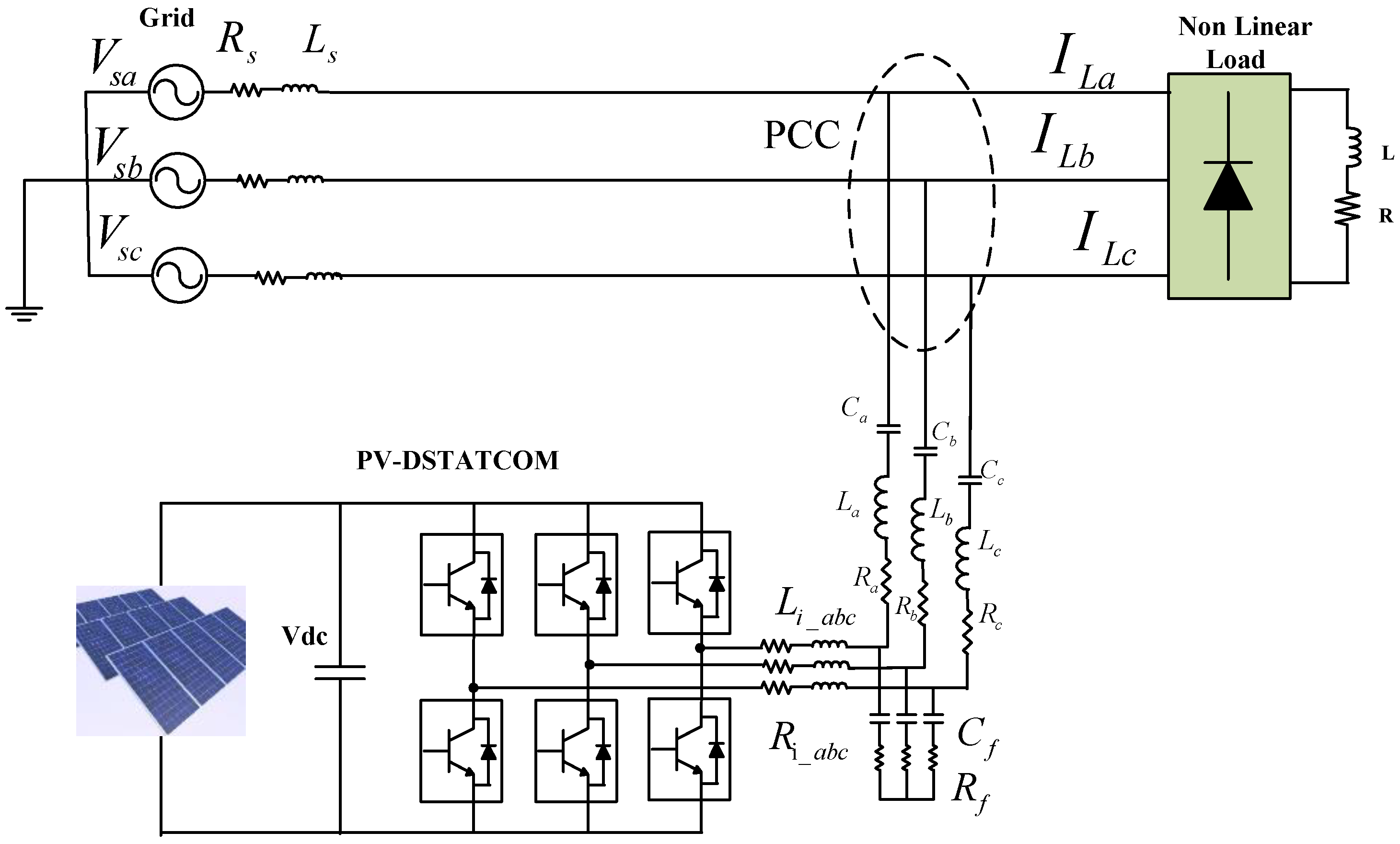
  • The LCLC-PV-DSTATCOM was designed for the distribution system to enhance the power quality under dynamic load conditions.
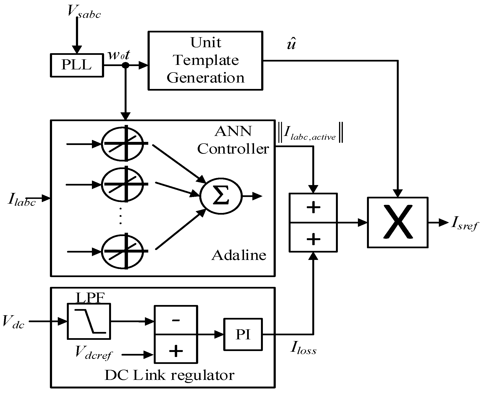
  • An adaptive ADALINE-based controller was proposed for the suitable control of the considered PV-DSTATCOM. An ADALINE-based controller provides adaptivity regarding power quality issues based on the learning mechanism.
  • The performance of the ADALINE-based controller for the PV-DSTATCOM system was analyzed under various dynamic load conditions and compared with the performance of conventional controllers.
In the present work, the ADALINE algorithm was proposed to control the PV-DSTATCOM. In addition, the ADALINE algorithm was compared with the BP, ILST, and SRFT algorithms and the comparison results demonstrated its superiority under various load conditions.
Section 2 describes the PV based DSTATCOM system configuration. The BP, ILST, and SRFT algorithms are presented in Section 3, and modelled by using MATLAB/Simulink. Section 4 describes in detail the proposed ADALINE control method. Section 5 explains the comparative breakdown of the 4 controllers with the aid of the simulation results. The work is concluded in Section 6 summarizing the outcomes, the benefits of the proposed method and the perspectives on future works.

2. System Configuration of the PV-Based DSTATCOM

This considered system comprised a solar PV string in series and parallel connections for a required output power rating, an interfacing inductor, an RC filter, and a voltage source converter (VSC). The PV module was affiliated with the VSC, which not only acted as a converter but also performed the role of a compensator for the mitigation of power quality problems. It was then interfaced to the 3-Ø grid system connected with various types of loads, such as non-linear loads, non-linear with linear balanced loads, non-linear with linear unbalanced loads, and a thyristor load with dynamic firing angles. For maximum power extraction from the solar array, the incremental conductance (IncCond) algorithm was incorporated into the system. The PV-DSTATCOM and the connected LCLC network are represented in Figure 1. The system parameters can be found in Appendix A.

3. Control Methods Description

DSTATCOM offers a total power component that is suitable for a nonlinear load for power quality enhancement and harmonic suppression; it ensures that the source current always has a unity power factor when viewed from the source side. As the source only delivers actual power, load equilibrium is achieved by balancing the reference source currents, facilitating the DSTATCOM network’s controller switching [1,2,3,4,5,10,11,12,13,14,15]. Several approaches are employed to extract the fundamental frequency’s real component from the load current. In the following subsections, the algorithms used in this study are described.

3.1. Synchronous Reference Frame Theory (SRFT)

The currents of reference compensation were calculated in two phases. The load current of the a-b-c reference frame was transformed to the α-β reference frame’s load current. The DC components were removed using low-pass filters and translated back into the stationary reference frame and subsequently into the a-b-c reference frame [16], which formed the basic components of load currents, as indicated in Equation (1). To create the voltage templates, a phase-locked loop was employed.
I l d = I d D C + I d A C ; I l q = I q D C + I q A C
In Figure 1, IdDC is the filtered-out DC component of the input current and IQdc is the filtered-out quadrature DC component of the input current.
In the hysteresis current band controller, the reference current obtained following an inverse Park and Clarke transformation was compared with the measured source currents, and switching pulses were generated suitably for the IGBT switches, as illustrated in Figure 2. Since PV power was employed, an appropriate maximum power point tracker (MPPT) near the solar array was constructed for maximum power extraction [1,2,3,13,15].

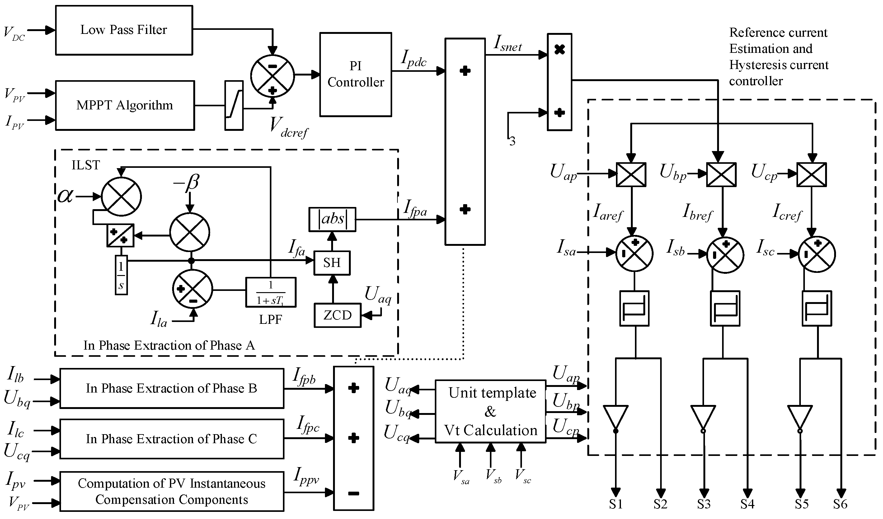
3.2. Improved Linear Sinusoidal Tracer (ILST)

The structure of the ILST is depicted in Figure 3. Load currents samples were used to collect the active power component, as well as the basic current output from the ILST at zero crossings of the fundamental phase load component. To synchronize the currents supplied into the grid, templates built from point of common coupling (PCC) voltages were employed. The only active component of current was transferred across the grid since grid currents were in the UPF.
The solar PV power, loads, and the grid should all have the net active power balance in the system, given as in Equation (2):
I s n e t = I f p + I p d c I p v
where Isnet is the net current, Ifp is the fundamental component, Ipdc is the filtered-out component after the PI controller, and IPV is the current from the photovoltaic system. The net fundamental in-phase load component Ifp is given as in Equation (3) [17]:
I f p = I f p a + I f p b + I f p c
where Ifpa, Ifpb, and Ifpc are the fundamental components of load current in phase with source voltages of phase a, phase b, and phase c, respectively.
In the hysteresis current band controller, the produced reference current was compared with the measured source currents, and switching pulses were correspondingly created for the IGBT switches [16,17,18]. As illustrated in Figure 3, the MPPT was incorporated within the control algorithm.

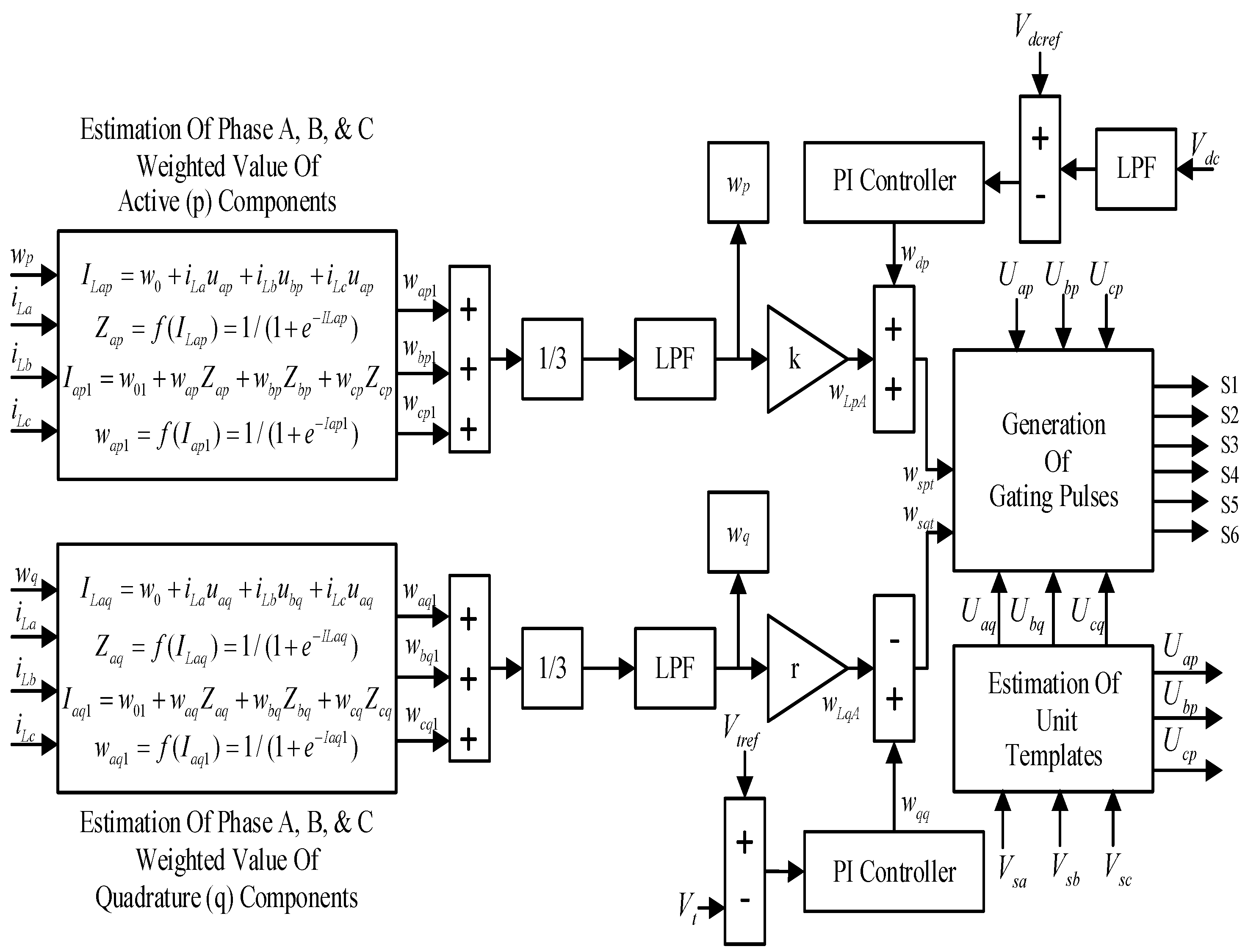
3.3. Backpropagation Algorithm

The backpropagation algorithm is a neural network. It is particularly smooth regarding weight correction and updating because it incorporates three layers that implement the following three functions: (1) feed-forward of the input signal training and computation, (2) backpropagation of the error signals, and (3) upgrading of training weights [19,20]. By establishing a starting weight, the current technique was utilized to estimate the three-phase weighted value of the load active and reactive power components. This value was updated at every iteration till the error was constant and at a minimum thanks to the feedback loop (backpropagation). The algorithm was accurate despite the slow nature of convergence due to a large number of training steps [21,22].
The reference current was the summation of active and reactive power components, which was then compared with the sensed source currents in the hysteresis current band controller. Switching pulses are generated accordingly for the IGBT switches, as shown in Figure 4.
I s a r e f = I s a p + I s a q , I s b r e f = I s b p + I s b q , I s c r e f = I s c p + I s c q
Since PV power is used, a suitable MPPT was implemented near the solar array for maximum power extraction.

4. The ADALINE-Based Control Method

This study proposed an ADALINE to generate a reference fundamental active load current. It is a neural network with two layers, namely, the input and output layers invented by Widrow and Hoff [23]. The neural network is based on the least-mean-square algorithm (LMS), which is a simple tool that can identify and estimate linear real-world problems and, in some cases, non-linear problems with self-learning [23].
The inputs of the network are multiplied by the weights, which are modified at each iteration and added up to obtain an estimated output. The output is compared with the target signal and the comparison error is used by the algorithm to modify the weights. The main aim of the network is to extract the fundamental signal from the distorted load signals. The basic structure of the ADALINE is shown in Figure 5.
The distorted load current containing harmonics can be expressed using the Fourier series as a sum of sine and cosine. The main aim is to find the coefficient of sine and cosine components, which are an and bn, respectively [23,24,25,26,27].
The sine and cosine functions are known as the input to the ADALINE network, without their amplitudes. The unknown amplitudes are considered the modifiable weights that are updated at each iteration. The output of the network is the load current (y) to be estimated, whereas the load current measured is the target signal (tg). The load current estimated [26] is defined in Equation (5):
y k = n = 1 , 5 , 7 M a n k sin ( 2 π n f 0 t k ) + b n k cos ( 2 π n f 0 t k )
The load current to be estimated can be written in a Fourier series sampled at tk = kTs, where k is the sampling index, Ts is the sampling time or interval, n is the index of the harmonic, and M is the highest order of the harmonics. In this work, we considered all the odd harmonics till M = 19 [28,29,30]. The network weights were updated using the LMS to minimize the error between the target load current and the load current estimated using the ADALINE.
The estimated load current is expressed in Equation (6):
y k = ( w k ) T x k
where
( x k ) T = [ sin ( ω 0 t k )    sin ( 5 ω 0 t k ) sin ( M ω 0 t k )    cos ( ω 0 t k )   cos ( 5 ω 0 t k ) cos ( M ω 0 t k ) ]
and
( w k ) T = [ a 1 k   a 5 k .   a M k         b 1 k   b 5 k .   b 5 k ]
The final weight updating rule of the network used in the ADALINE is defined in Equation (9):
w k = w k 1 η Ε k ( w ) = w k 1 + η e k x k
Figure 5 and Figure 6 illustrate the ADALINE for the extraction of the active fundamental component present in the load current. In particular, the fundamental signal is multiplied by the unit templates to generate the reference source currents. The produced reference signals are compared with the actual source currents using the hysteresis band current controller to provide the switching signals for the inverter. Even in this case, since PV power is used, a suitable MPPT [31,32,33] was implemented near the solar array for maximum power extraction.

5. Results and Analysis

The considered system was modeled and simulated by using the MATLAB/Simulink environment. The simulation parameters are provided in Appendix A and Appendix B. The performance of PV-DSTATCOM was analyzed by adopting various controllers and different load conditions.

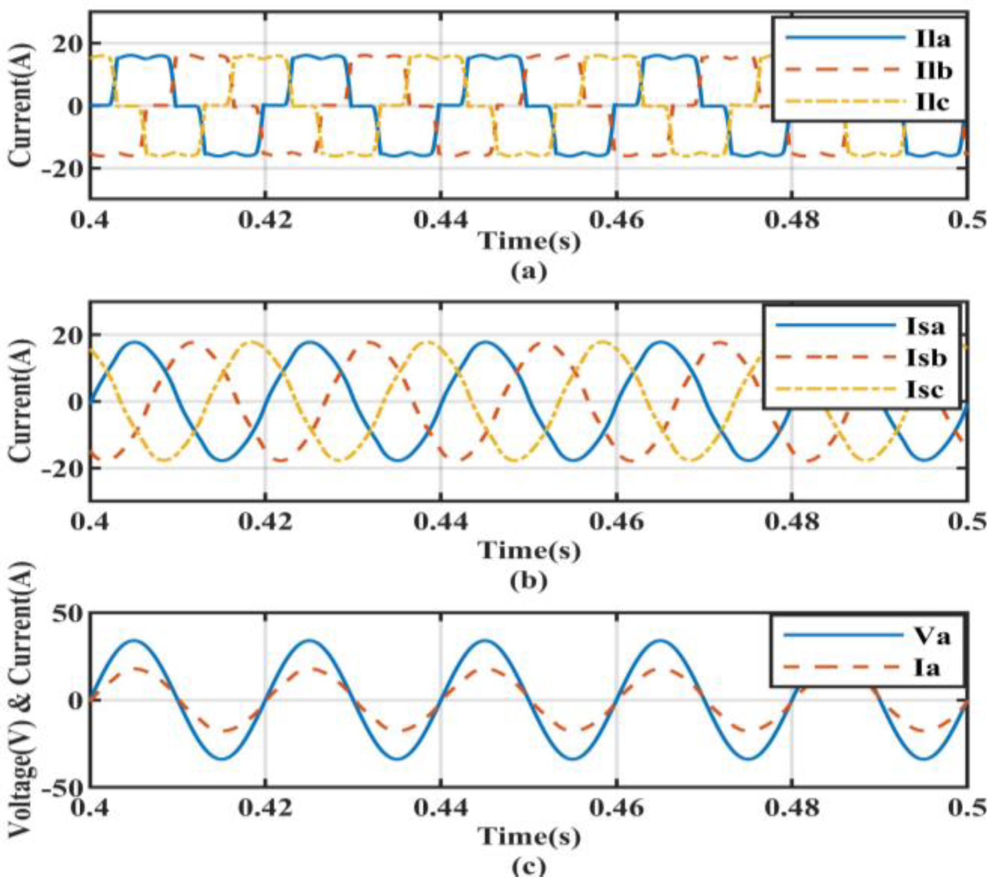
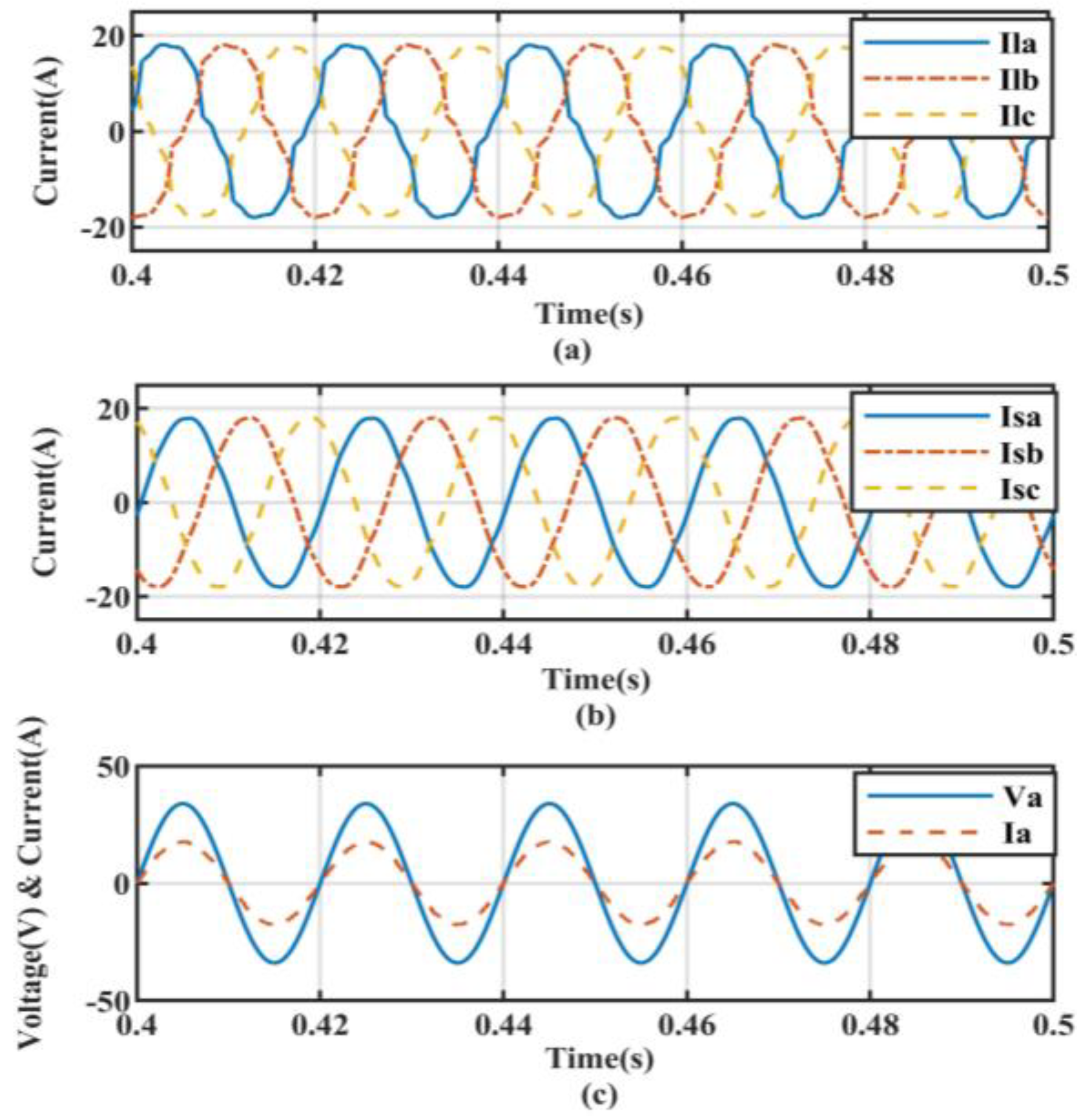
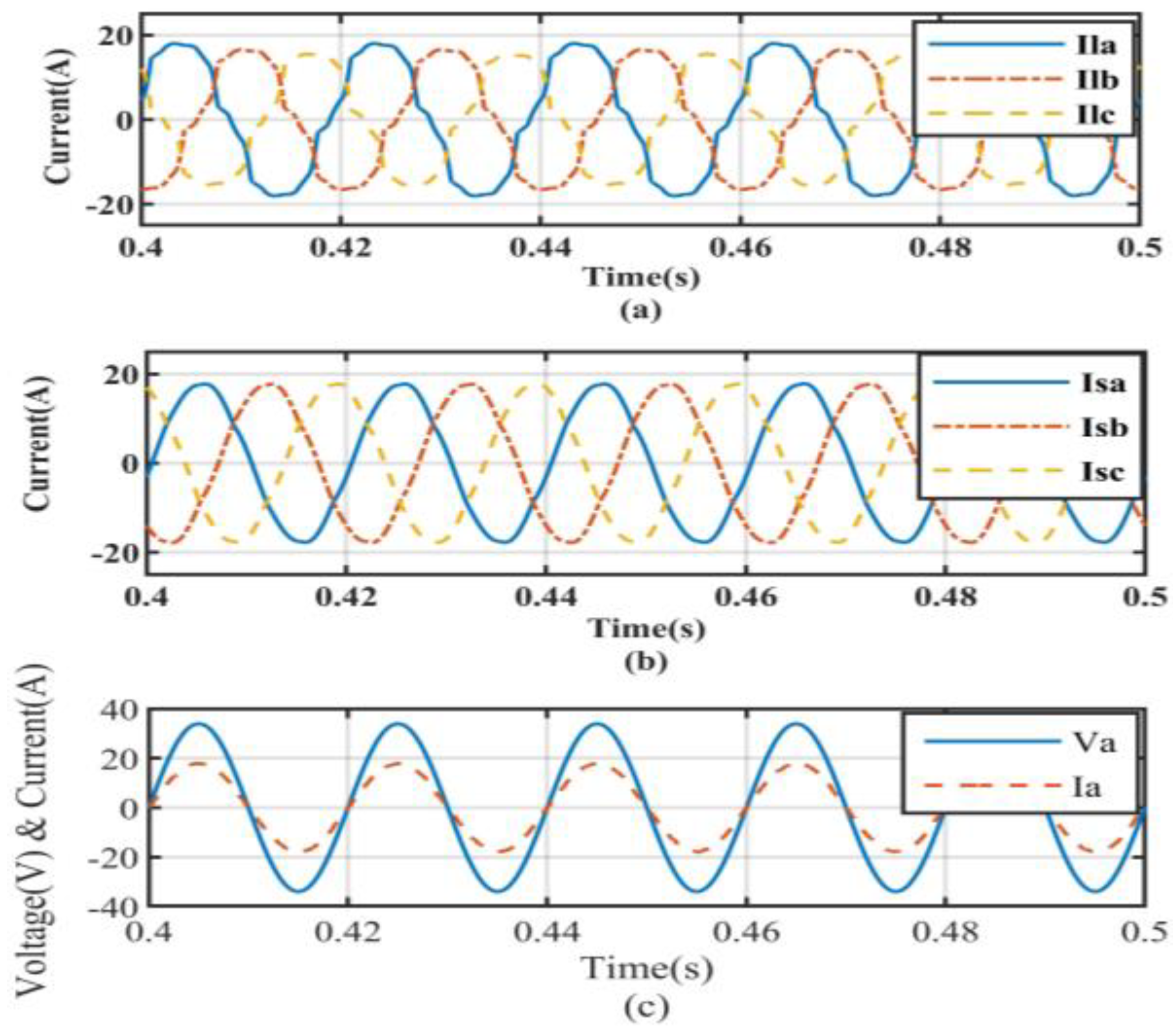
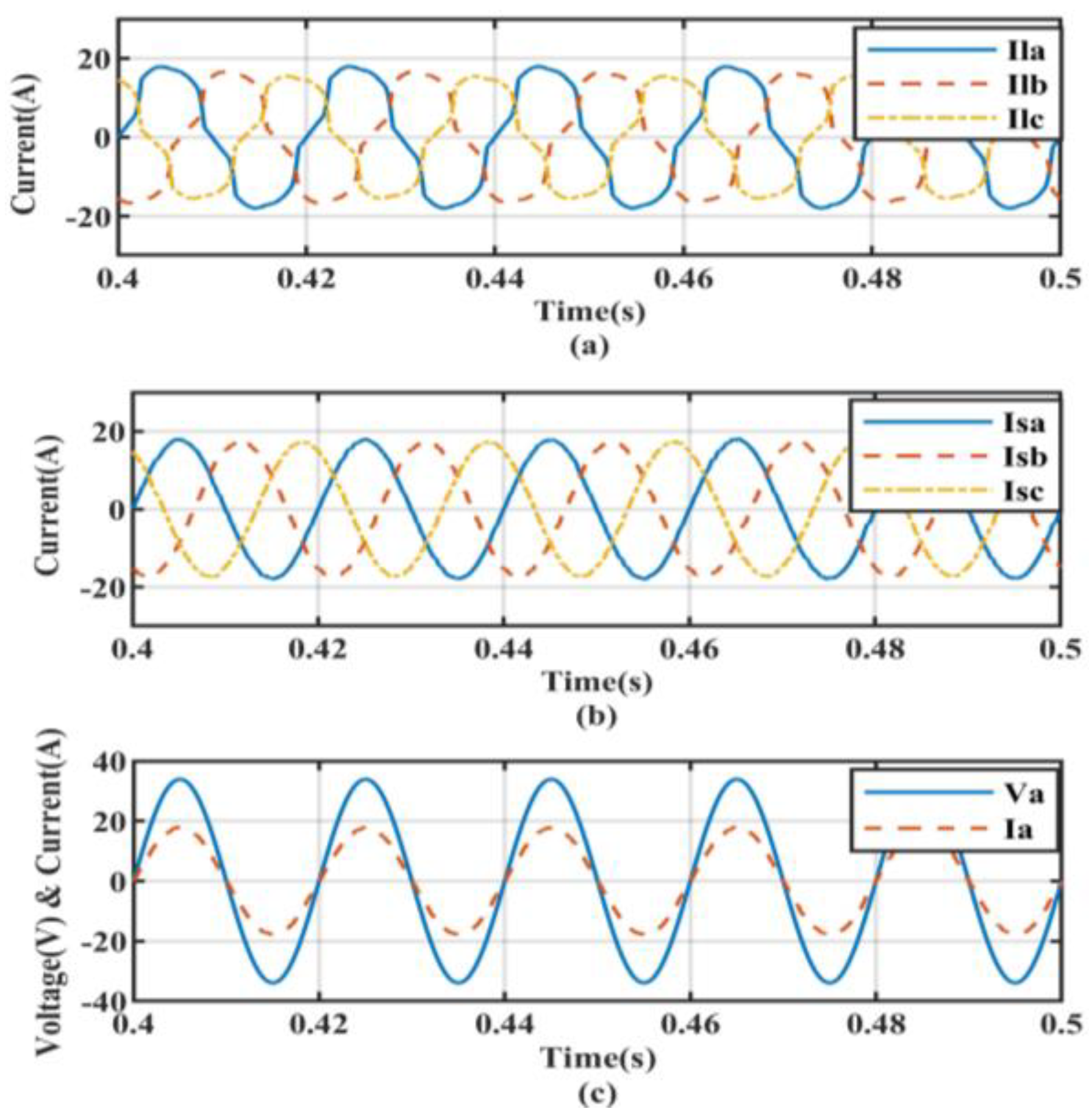
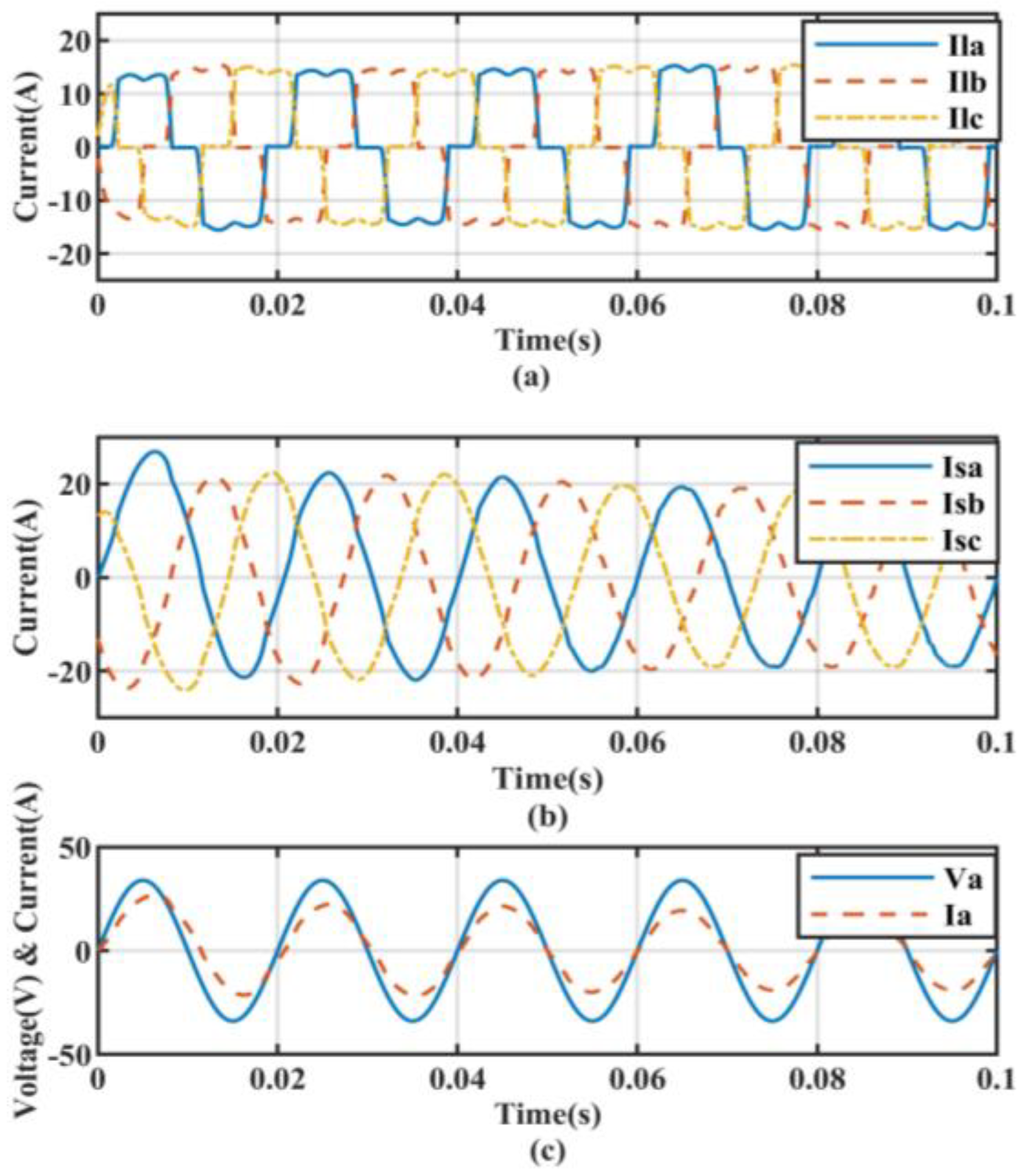
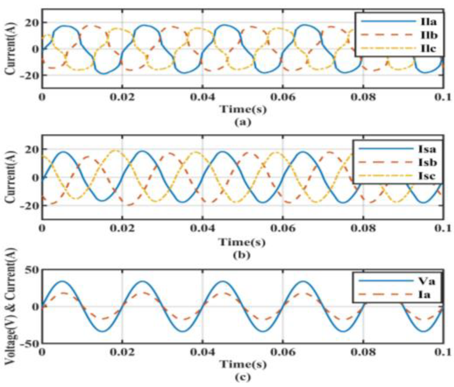
5.1. Performance under Non-Linear Load Conditions

The system under non-linear loading conditions was simulated; examples of such loads include power converters, solid-state drives, and adjustable speed drives. The performances of the system under the considered conventional control mechanisms SFRT, ISLT, and BP were analyzed in Figure 7, Figure 8 and Figure 9, respectively. The harmonics from the source currents were mitigated using the proposed ADALINE-based controller to make the source currents approximately sinusoidal, as shown in Figure 10. The total harmonic distortion of the source currents under various conditions with considered controllers are listed in Table 1 to evaluate the performance.

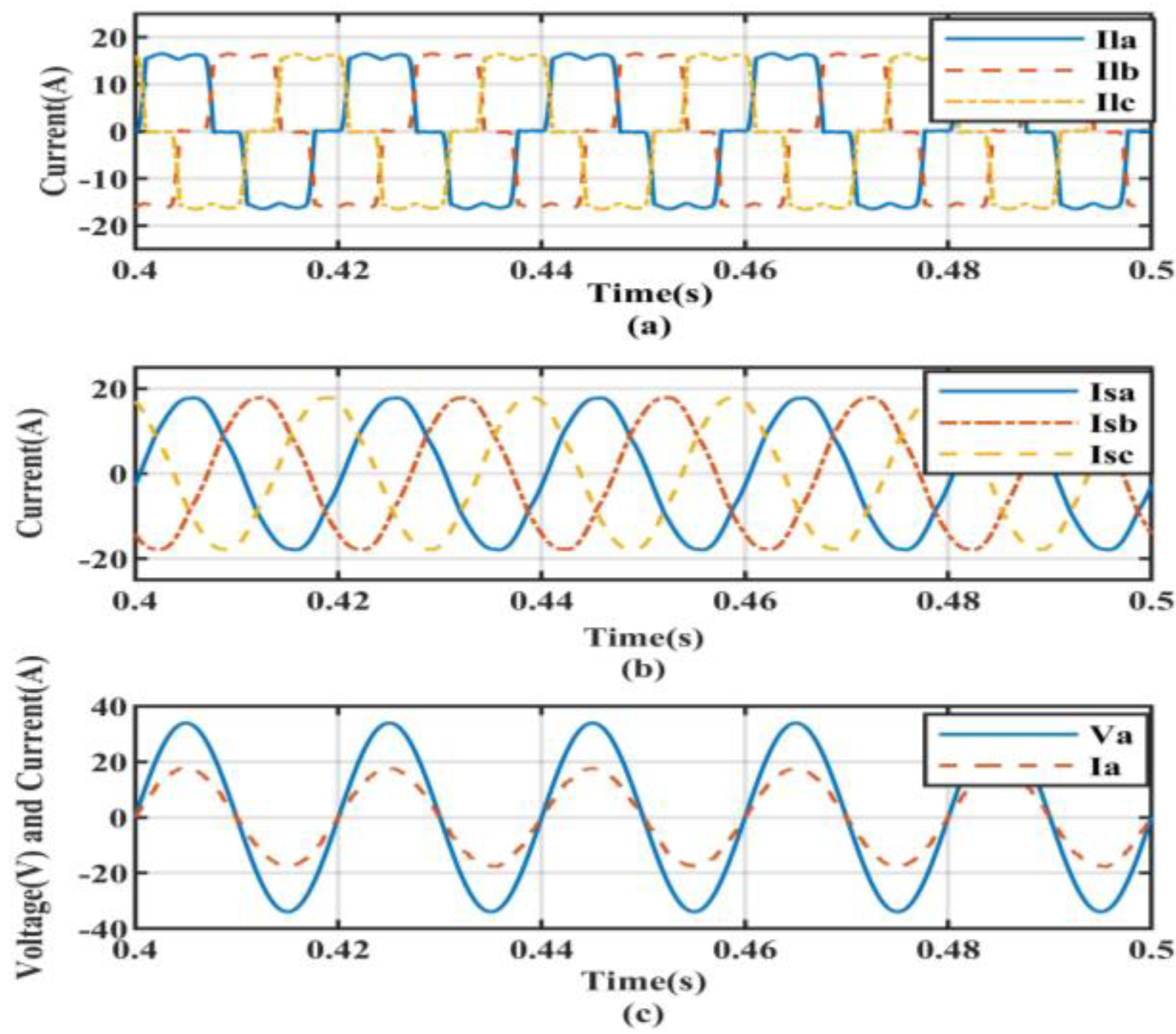
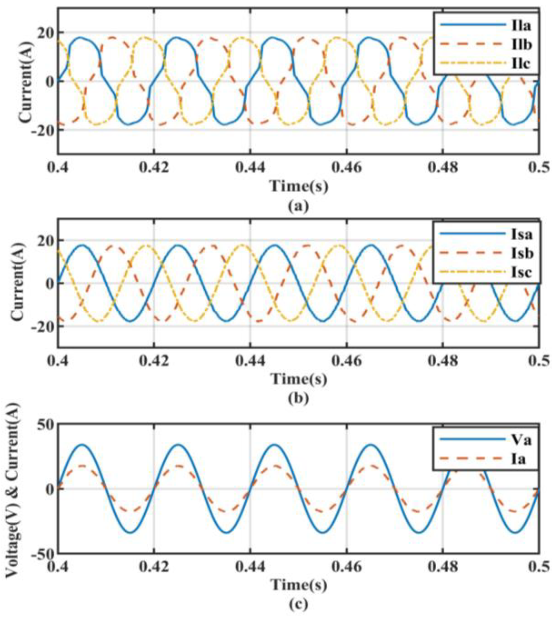
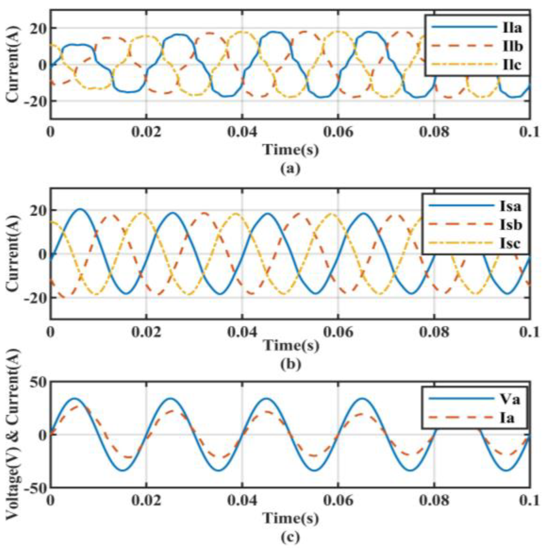
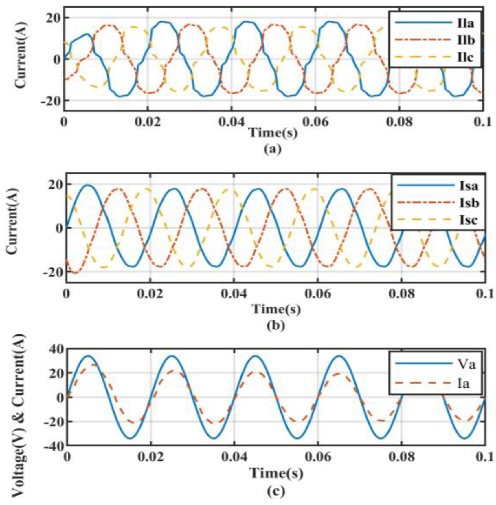
5.2. Non-Linear Load with Linear Balanced Load Conditions

The system under non-linear loading conditions along with linear balanced loads was simulated. Examples of such linear loads include incandescent lamps and heaters. The efficiency of the proposed ADALINE controller can be clearly analyzed by comparing the results obtained by the SRFT, ISLT, and BP in Figure 11, Figure 12 and Figure 13, respectively, with the results in Figure 14. The ADALINE-based controller for PV-DSTATCOM eliminates harmonics from source current more efficiently than other aforementioned controllers. Therefore, the proposed controller shows its superiority.

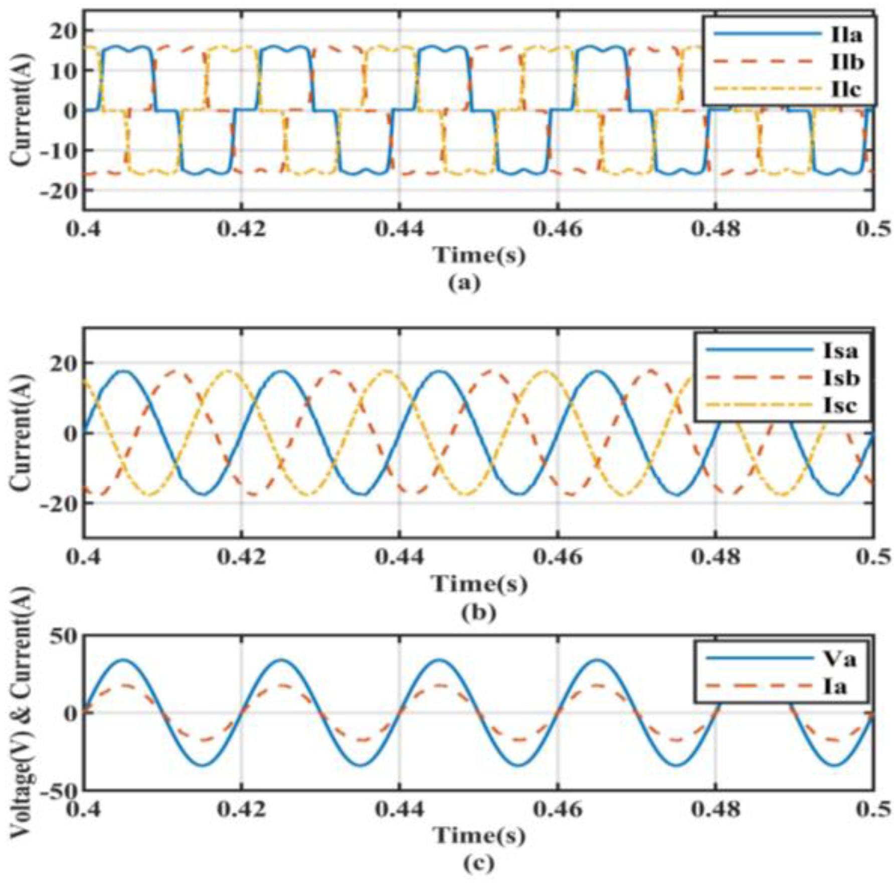
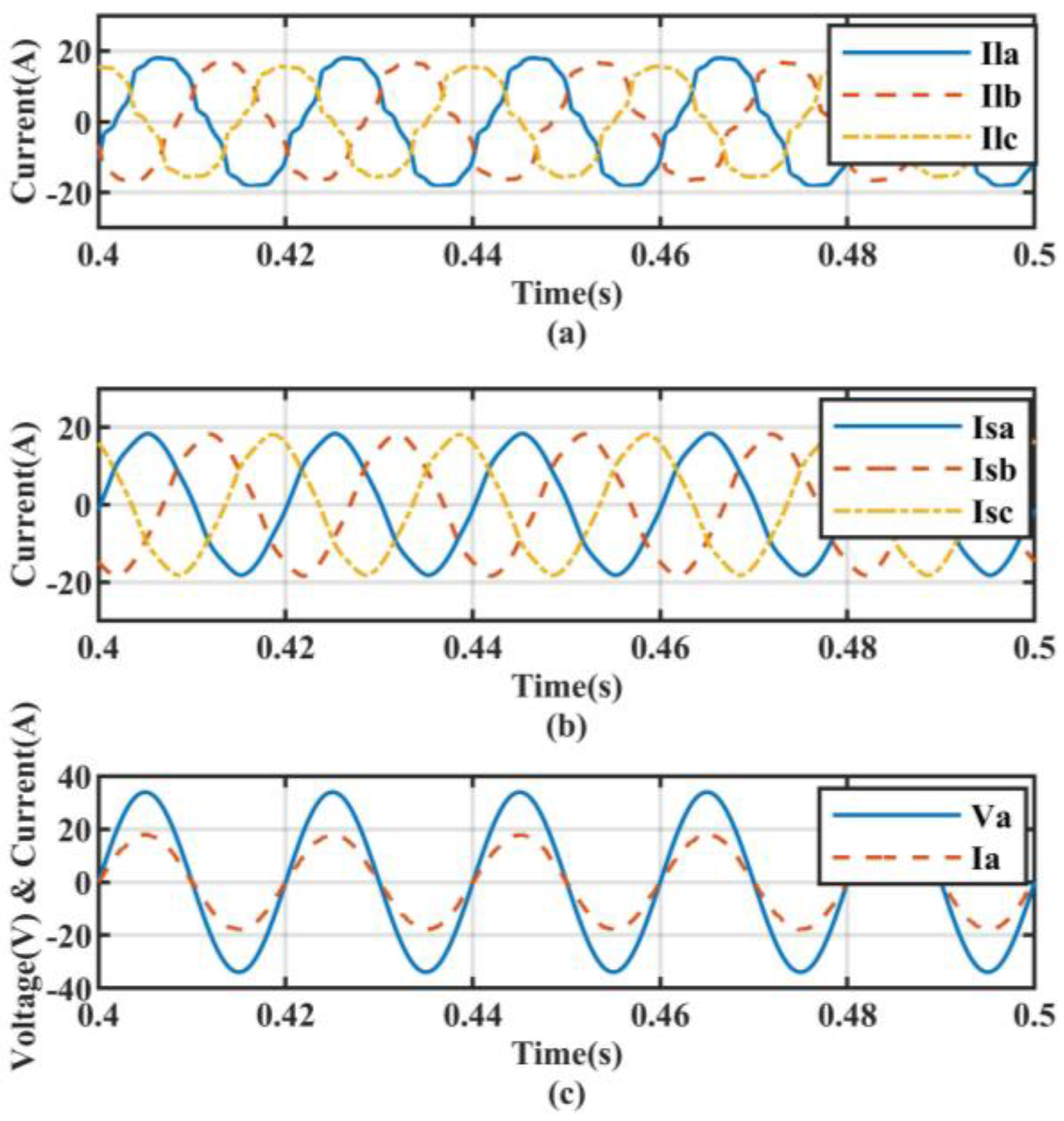
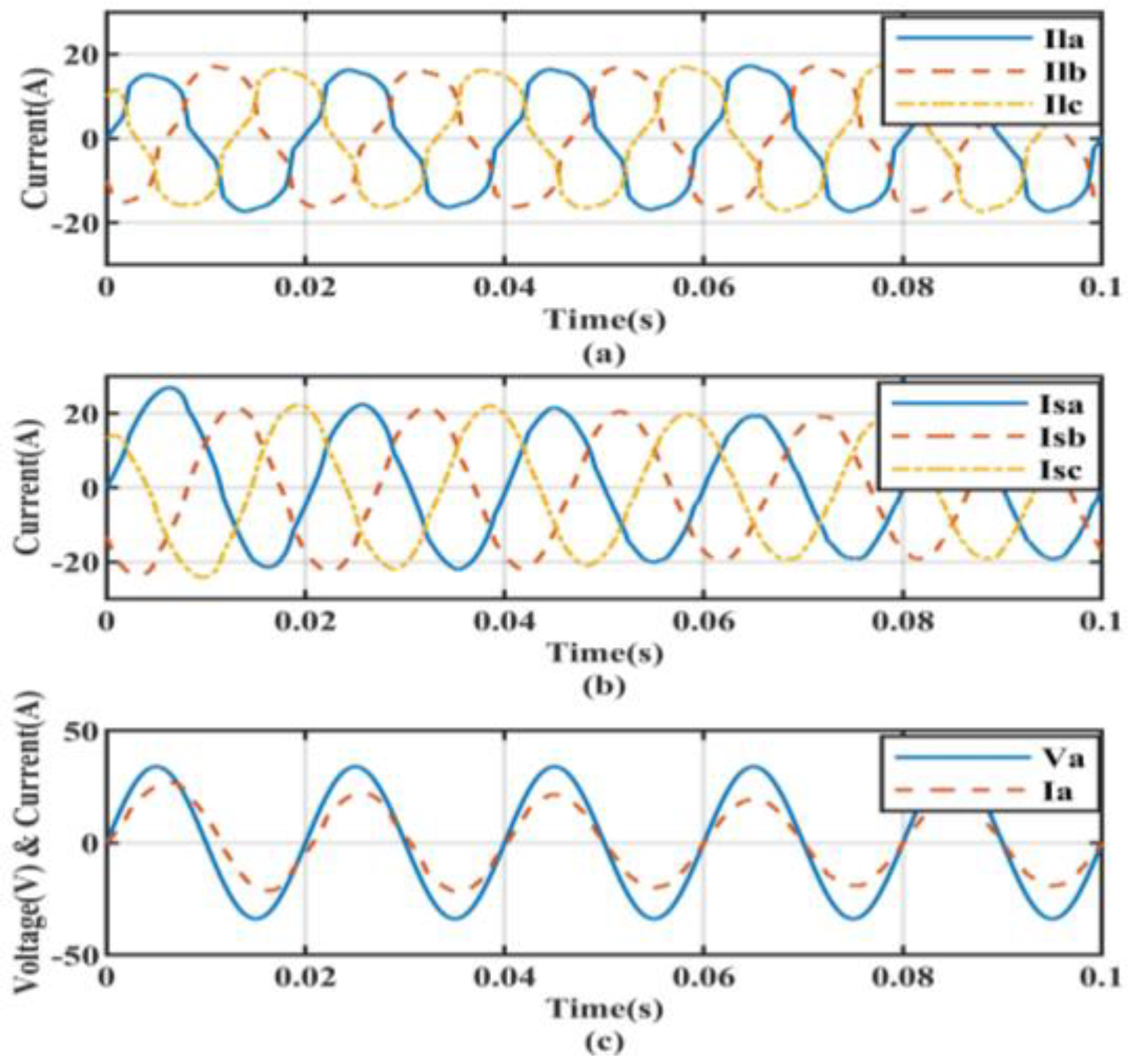
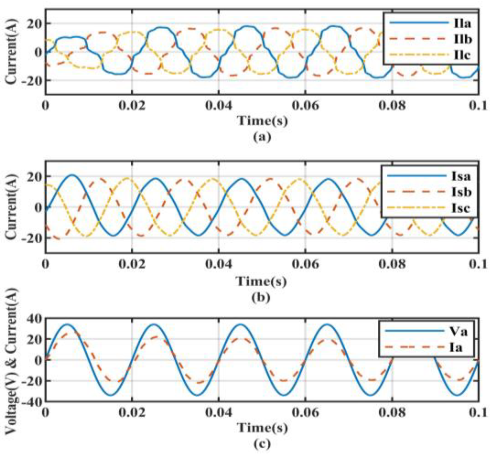
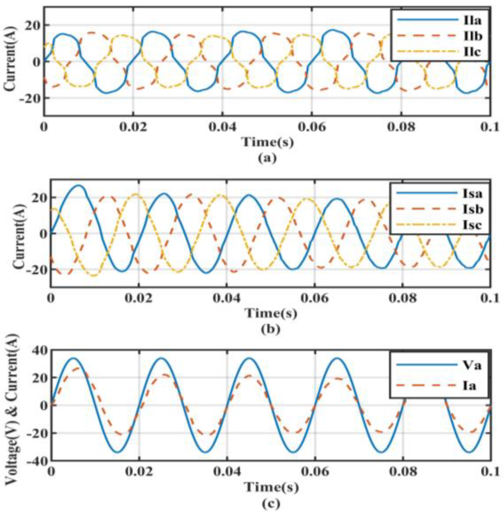
5.3. Non-Linear Load with Linear Unbalanced Load Conditions

The system under non-linear loading conditions along with linear unbalanced loads was simulated. In an unbalanced three-phase load, the load was not equally distributed over all three phases; large single-phase loads lead to a lack of balance in the other two phases. By comparing the results shown in Figure 15, Figure 16, Figure 17 and Figure 18, it can be noticed how the proposed ADALINE controller outperformed the conventional controllers.

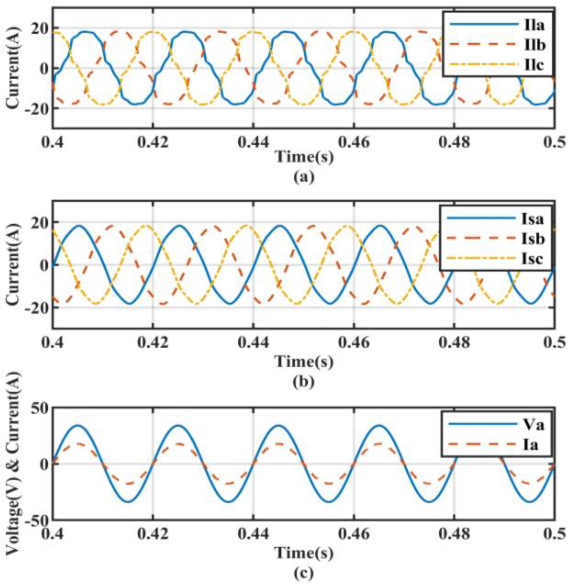
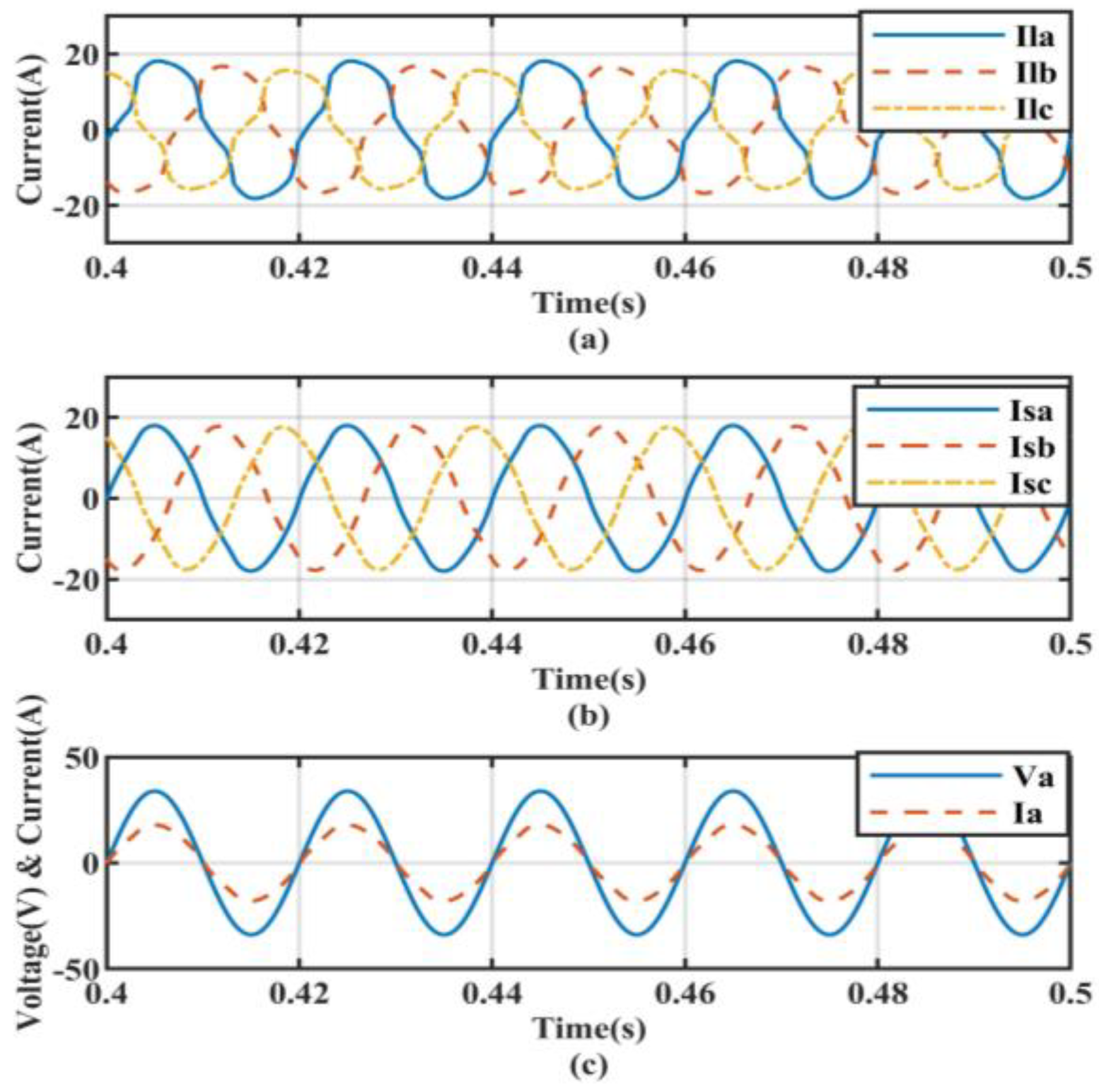
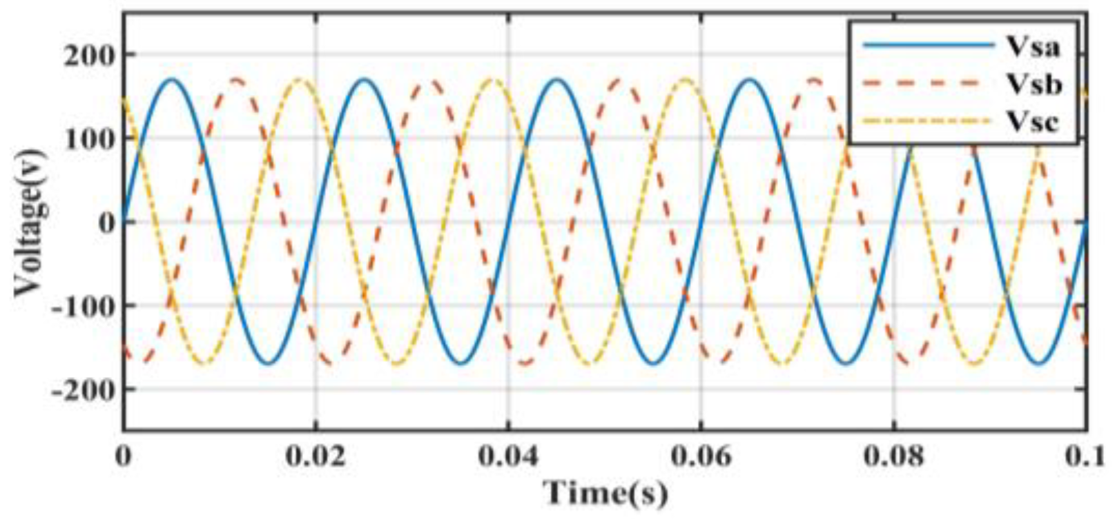
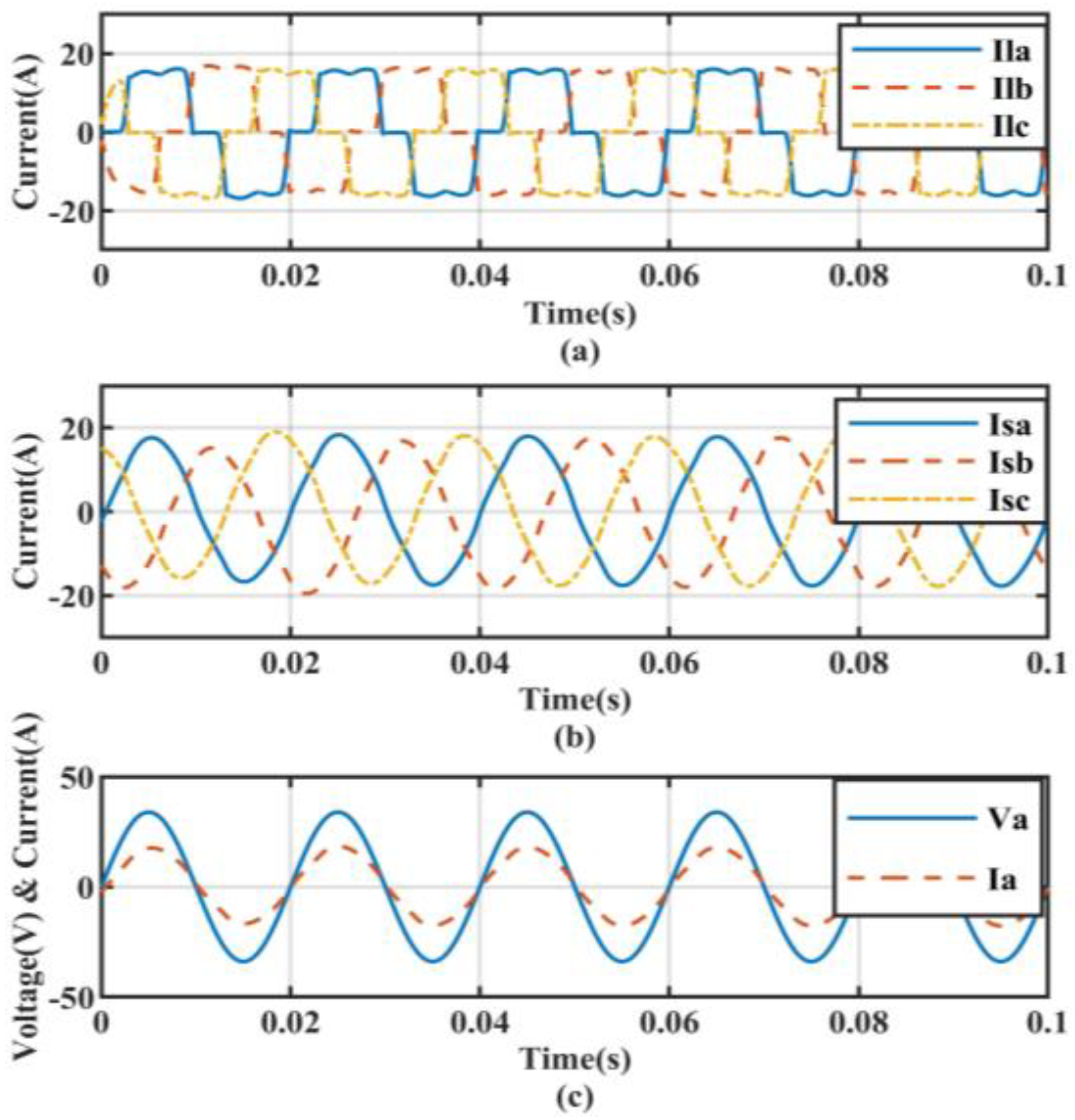
5.4. Transient State Analysis for Ideal Source Voltage Condition

The performance of the system under varying loads was observed and analyzed; the following results were obtained for a transient state condition at the moment when the loads were thrown into the system under a non-distorted source voltage condition. The source voltage is represented in Figure 19. In particular, the efficiency of the proposed ADALINE-based controller was superior to the SRFT controller presented in Figure 20 and the ILST control strategy shown in Figure 21. Moreover, the performance of the system was also compared with transient state condition results obtained from the backpropagation algorithm in Figure 22 and the results of the ADALINE-based controller in Figure 23 for the transient state analysis. From the simulation results, it can be concluded that the ADALINE-based controller has higher efficiency toward the elimination of total harmonics distortions from the source currents.
The simulated results are given in Figure 24 for the SRFT controller, Figure 25 for the ILST controller, and Figure 26 for the BP method. The proposed methodology under the considered situation showed superior performance, as presented in Figure 27.
The system under non-linear loading conditions along with linear unbalanced loads was simulated. The results of the application of the SRFT, ILST, and BP methods are shown in Figure 28, Figure 29 and Figure 30, respectively. The proposed methodology showed superior performance, as presented in Figure 31.
Table 1 reports the performance of controllers for the PV-based DSTATCOM system. For the evaluation of the controllers, THD was taken into account before the compensation and after the compensation. It can be observed that the performance of the proposed ADALINE-based controller was superior under various conditions of the load.

6. Conclusions

In this work, the control of a PV-tied improved hybrid DSTATCOM was studied. The system and the different controllers adopted were implemented using a MATLAB and SIMULINK tool. A new ADALINE control model is proposed and applied to the system and a performance comparison was done with BP, ILST, and SRFT algorithms. In particular, the SRFT algorithm did not perform well with distorted source voltage conditions due to the presence of the phase-locked loop. In contrast, the ILST performed well under these conditions, and the response time was also good, but the computational effort was high. However, the performance under various dynamic conditions was not satisfactory.
The artificial-neural-network-based algorithms, such as the BP and ADALINE, required less computational effort and due to the frequent updating of weights and the minimization of errors, such algorithms performed extremely well. In this work, the effectiveness of the proposed ADALINE-based controller was analyzed in comparison with the other controllers for harmonic mitigation, reactive power removal, and load balancing under various load conditions. From the performed simulation tests, it can be concluded that the proposed controller outperformed the compared conventional controllers.
The considered topology of the PV-DSTATCOM and the controller played a major role in the elimination of harmonics in the source currents. Therefore, in future research, the development of a new topology for a PV-based grid connected system, as well as other renewable energy sources, such as fuel cells and wind energy, can be considered. To enhance the performance of the system, artificial-intelligence-based and Petri net-based [33] controllers can be developed and implemented.

Author Contributions

Conceptualization, S.M. and S.K.D.; methodology, S.R.; software, S.M.L. and P.K.M.; validation, S.M.L., H.J.G. and P.K.M.; formal analysis, S.K.D. and M.R.; investigation, S.K.D. and M.R.; resources, S.R.; data curation, S.K.D.; writing—original draft preparation, S.M.; writing—review and editing, S.M. and S.K.D.; visualization, S.M.; supervision, M.R. and S.K.D.; project administration, S.K.D. All authors have read and agreed to the published version of the manuscript.

Funding

This research received no external funding.

Data Availability Statement

The data can be shared upon genuine request to the author.

Conflicts of Interest

The authors have no conflict of interest.

Appendix A

SRFT: PI controller gains—Kp = 1, Ki = 5, and LPF cutoff frequency = 50 Hz.
ILST: bandwidth (α) = 100 rad/s, tuning frequency (β) = 314.14 Hz, PI controller gains—Kp = 1, Ki = 5, and LPF cutoff frequency = 50 Hz.
BP: learning rate (µ) = 0.6, scaling factor for the in-phase component (k) = 0.4, scaling factor for the quadrature component (r) = 0.2, LPF cutoff frequency = 50 Hz, PI controller gains—Kp = 1 and Ki = 5. ADALINE: learning rate (µ) = 0.6, PI controller gains—Kp = 1 and Ki = 5.

Appendix B

PV array data: rated maximum power (Pmax) = 227.25 W, short-circuit current (Ipv) = 8.2 A, open-circuit voltage (Voc) = 32.8 V, number of PV array in series = 10, diode ideality factor = 1.0007, current at MPP (Imp) = 7.5 A, the voltage at MPP (Vmp) = 30.3 V, series and shunt resistance (Rs, Rsh) = 0.12511Ω and 86.5718Ω, S.C current coefficient (Ki) in %/°C = 0.07, O.C voltage coefficient (Kp) in %/°C = 0.35599, number of PV arrays in parallel = 5, and cells per module = 54.

References

  1. Singh, B.; Chandra, A.; Al-Haddad, K. Power Quality Problems and Mitigation Techniques; John Wiley & Sons: Hoboken, NJ, USA, 2014. [Google Scholar]
  2. Singh, B.; Jayaprakash, P.; Kothari, D.P.; Chandra, A.; Al Haddad, K. Comprehensive Study of DSTATCOM Configurations. IEEE Trans. Ind. Inform. 2014, 10, 854–870. [Google Scholar] [CrossRef]
  3. Pal, Y.; Swarup, A.; Singh, B. A review of compensating type custom power devices for power quality improvement. In Proceedings of the 2008 Joint International Conference on Power System Technology and IEEE Power India Conference, New Delhi, India, 12–15 October 2008. [Google Scholar]
  4. Mishra, S.; Dash, S.K.; Ray, P.K. Performance analysis of L-type PV-DSTATCOM under ideal and distorted supply voltage. In Proceedings of the 2016 IEEE Students’ Technology Symposium (TechSym), Kharagpur, India, 30 September–2 October 2016; pp. 180–185. [Google Scholar] [CrossRef]
  5. Mishra, S.; Ray, P.K. Power quality improvement with shunt active filter under various mains voltage using Teaching Learning Based optimization. In Proceedings of the 2015 2nd International Conference on Recent Advances in Engineering & Computational Sciences (RAECS), Chandigarh, India, 21–22 December 2015. [Google Scholar]
  6. Villalva, M.G.; Gazoli, J.R.; Filho, E.R. Comprehensive approach to modeling and simulation of photovoltaic arrays. IEEE Trans. Power Electron. 2009, 24, 1198–1208. [Google Scholar] [CrossRef]
  7. Esram, T.; Chapman, P.L. Comparison of Photovoltaic Array Maximum Power Point Tracking Techniques. IEEE Trans. Energy Convers. 2007, 22, 439–449. [Google Scholar] [CrossRef] [Green Version]
  8. Kouro, S.; Leon, J.I.; Vinnikov, D.; Franquelo, L.G. Grid-Connected Photovoltaic Systems: An Overview of Recent Research and Emerging PV Converter Technology. IEEE Ind. Electron. Mag. 2015, 9, 47–61. [Google Scholar] [CrossRef]
  9. Patel, N.; Gupta, N.; Babu, B.C. Photovoltaic system operation as DSTATCOM for power quality improvement employing active current control. IET Gener. Transm. Distrib. 2020, 14, 3518–3529. [Google Scholar] [CrossRef]
  10. Labeeb, M.; Lathika, B. Design and analysis of DSTATCOM using SRFT and ANN-fuzzy based control for power quality improvement. In Proceedings of the 2011 IEEE Recent Advances in Intelligent Computational Systems, Trivandrum, India, 22–24 September 2011; pp. 274–279. [Google Scholar] [CrossRef]
  11. Singh, B.; Dube, S.K.; Arya, S.R. An improved control algorithm of DSTATCOM for power quality improvement. Int. J. Electr. Power Energy Syst. 2015, 64, 493–504. [Google Scholar] [CrossRef]
  12. Singh, B.; Solanki, J. A Comparison of Control Algorithms for DSTATCOM. IEEE Trans. Ind. Electron. 2009, 56, 2738–2745. [Google Scholar] [CrossRef]
  13. Masand, D.; Jain, S.; Agnihotri, G. Control algorithms for distribution static compensator. In Proceedings of the 2006 IEEE International Symposium on Industrial Electronics, Singapore, 24–26 May 2006. [Google Scholar]
  14. Reddy, M.V.K.; Das’s, D.T.; Pulla, D.S.; Veni, D.K.K. Performance Analysis Of D-Statcom Compensator Using Control Techniques for Load Compensation. Int. J. Electr. Electron. Eng. Res. 2011, 1, 149–171. [Google Scholar]
  15. Prasad, A.G.; Dheeraj, K.; Kumar, A.N. Comparison of Control Algorithms for Shunt Active Filter for Harmonic Mitigation. Int. J. Eng. Res. Technol. 2012, 1, 5. [Google Scholar]
  16. Du, S.-W.; Su, J.-M. Analysis of an improved harmonic currents detection method based on LST. In Proceedings of the 2011 2nd International Conference on Artificial Intelligence, Management Science and Electronic Commerce (AIMSEC), Dengfeng, China, 8–10 August 2011; pp. 3755–3759. [Google Scholar] [CrossRef]
  17. Singh, B.; Arya, S.R. Adaptive Theory-Based Improved Linear Sinusoidal Tracer Control Algorithm for DSTATCOM. IEEE Trans. Power Electron. 2012, 28, 3768–3778. [Google Scholar] [CrossRef]
  18. Singh, B.; Jain, C.; Goel, S. ILST Control Algorithm of Single-Stage Dual Purpose Grid Connected Solar PV System. IEEE Trans. Power Electron. 2013, 29, 5347–5357. [Google Scholar] [CrossRef]
  19. Jayachandran, J.; Sachithanadam, R.M. Neural Network-Based Control Algorithm for DSTATCOM Under Nonideal Source Voltage and Varying Load Conditions. Can. J. Electr. Comput. Eng. 2015, 38, 307–317. [Google Scholar] [CrossRef]
  20. Agarwal, R.K.; Hussain, I.; Singh, B. Application of LMS-based NN structure for power quality enhancement in a distribution network under abnormal conditions. IEEE Trans. Neural Netw. Learn. Syst. 2018, 29, 1598–1607. [Google Scholar] [CrossRef] [PubMed]
  21. Singh, B.; Arya, S.R. Back-propagation control algorithm for power quality improvement using DSTATCOM. IEEE Trans. Ind. Electron. 2014, 61, 1204–1212. [Google Scholar] [CrossRef]
  22. Kumar, P.; Mangaraj, M. DSTATCOM employing hybrid neural network control technique for power quality improvement. IET Power Electron 2017, 10, 480–489. [Google Scholar] [CrossRef]
  23. Qasim, M.; Khadkikar, V. Application of Artificial Neural Networks for Shunt Active Power Filter Control. IEEE Trans. Ind. Inform. 2014, 10, 1765–1774. [Google Scholar] [CrossRef]
  24. Chen, C.-I.; Hsu, C.-L.; Chen, C.-H. ADALINE-based shunt active power filter for power quality modification of power system. In Proceedings of the 2018 International Symposium on Computer, Consumer and Control (IS3C), Taichung, Taiwan, 6–8 December 2018. [Google Scholar]
  25. Mohan, H.M.; Dash, S.K. Performance assessment of a solar-powered three-phase modular multilevel converter with capacitor voltage balancing. In Proceedings of the 2022 Second International Conference on Power, Control and Computing Technologies (ICPC2T), Raipur, India, 1–3 March 2022; pp. 1–6. [Google Scholar] [CrossRef]
  26. Qasim, M.; Kanjiya, P.; Khadkikar, V. Optimal Current Harmonic Extractor Based on Unified ADALINEs for Shunt Active Power Filters. IEEE Trans. Power Electron. 2014, 29, 6383–6393. [Google Scholar] [CrossRef]
  27. Dash, S.K.; Garg, P.; Mishra, S.; Chakraborty, S.; Elangovan, D. Investigation of Adaptive Intelligent MPPT Algorithm for a Low-cost IoT Enabled Standalone PV System. Aust. J. Electr. Electron. Eng. 2022, 9, 261–269. [Google Scholar] [CrossRef]
  28. Ray, P.; Ray, P.K.; Dash, S.K. Power Quality Enhancement and Power Flow Analysis of a PV Integrated UPQC System in a Distribution Network. IEEE Trans. Ind. Appl. 2021, 58, 201–211. [Google Scholar] [CrossRef]
  29. Dash, S.K.; Roccotelli, M.; Khansama, R.R.; Fanti, M.P.; Mangini, A.M. Long Term Household Electricity Demand Forecasting Based on RNN-GBRT Model and a Novel Energy Theft Detection Method. Appl. Sci. 2021, 11, 8612. [Google Scholar] [CrossRef]
  30. Mishra, S.; Dash, S.K.; Ray, P.K.; Puhan, P.S. Analysis and experimental evaluation of novel hybrid fuzzy-based sliding mode control strategy for performance enhancement of PV fed DSTATCOM. Int. Trans. Electr. Energy Syst. 2021, 31, e12815. [Google Scholar] [CrossRef]
  31. Mohan, H.M.; Dash, S.K.; Ram, S.K.; Caesarendra, W. Performance assessment of three-phase PV tied NPC multilevel inverter based UPQC. In Proceedings of the 2022 International Conference on Intelligent Controller and Computing for Smart Power (ICICCSP), Hyderabad, India, 21–23 July 2022; pp. 1–5. [Google Scholar] [CrossRef]
  32. Dash, S.K.; Chakraborty, S.; Roccotelli, M.; Sahu, U.K. Hydrogen Fuel for Future Mobility: Challenges and Future Aspects. Sustainability 2022, 14, 8285. [Google Scholar] [CrossRef]
  33. Fanti, M.P.; Mangini, A.M.; Roccotelli, M. A Petri Net model for a building energy management system based on a demand response approach. In Proceedings of the 22nd Mediterranean Conference on Control and Automation (MED), Palermo, Italy, 16–19 June 2014; pp. 816–821. [Google Scholar] [CrossRef]
Figure 1. PV-DSTATCOM design configuration.
Energies 16 00323 g001
Figure 2. Structural diagram of the SRFT.
Energies 16 00323 g002
Figure 3. Structural diagram of the ILST.
Energies 16 00323 g003
Figure 4. Structural diagram of the BP.
Energies 16 00323 g004
Figure 5. Structural diagram of ADALINE.
Energies 16 00323 g005
Figure 6. Block diagram of reference current generation using ADALINE.
Energies 16 00323 g006
Figure 7. Results for the SRFT: (a) load current signal rich in harmonics, (b) the SRFT controller applied to a source current, and (c) reactive power compensation.
Energies 16 00323 g007
Figure 8. Results for the ILST: (a) load current signal rich in harmonics, (b) the ILST controller applied to a source current, and (c) reactive power compensation.
Energies 16 00323 g008
Figure 9. Results for the BP: (a) load current signal rich in harmonics, (b) the BP controller applied to source current, and (c) reactive power compensation.
Energies 16 00323 g009
Figure 10. Results for the ADALINE: (a) load current signal rich in harmonics, (b) the ADALINE controller applied to a source current, and (c) reactive power compensation.
Energies 16 00323 g010
Figure 11. Results for the SRFT: (a) load current signal rich in harmonics, (b) the SRFT controller applied to a source current, and (c) reactive power compensation.
Energies 16 00323 g011
Figure 12. Results for the ILST: (a) load current signal rich in harmonics, (b) the ILST controller applied to a source current, and (c) reactive power compensation.
Energies 16 00323 g012
Figure 13. Results for the BP: (a) load current signal rich in harmonics, (b) the BP controller applied to source current, and (c) reactive power compensation.
Energies 16 00323 g013
Figure 14. Results for the ADALINE: (a) load current signal rich in harmonics, (b) the ADALINE controller applied to source current, and (c) reactive power compensation.
Energies 16 00323 g014
Figure 15. Results for the SRFT: (a) load current signal rich in harmonics, (b) the SRFT controller applied to a source current, and (c) reactive power compensation.
Energies 16 00323 g015
Figure 16. Results for the ILST: (a) load current signal rich in harmonics, (b) the ILST controller applied to a source current, and (c) reactive power compensation.
Energies 16 00323 g016
Figure 17. Results for the BP: (a) load current signal rich in harmonics, (b) the BP controller applied to a source current, and (c) reactive power compensation.
Energies 16 00323 g017
Figure 18. Results for the ADALINE: (a) load current signal rich in harmonics, (b) the ADALINE controller applied to a source current, and (c) reactive power compensation.
Energies 16 00323 g018
Figure 19. Source voltage.
Energies 16 00323 g019
Figure 20. Results for the SRFT: (a) load current signal rich in harmonics, (b) the SRFT controller applied to a source current, and (c) reactive power compensation.
Energies 16 00323 g020
Figure 21. Results for the ILST: (a) load current signal rich in harmonics, (b) the ILST controller applied to a source current, and (c) reactive power compensation.
Energies 16 00323 g021
Figure 22. Results for the BP: (a) load current signal rich in harmonics, (b) the BP controller applied to a source current, and (c) reactive power compensation.
Energies 16 00323 g022
Figure 23. Results for the ADALINE: (a) load current signal rich in harmonics, (b) the ADALINE controller applied to a source current, and (c) reactive power compensation.
Energies 16 00323 g023
Figure 24. Results for the SRFT: (a) load current signal rich in harmonics, (b) the SRFT controller applied to a source current, and (c) reactive power compensation.
Energies 16 00323 g024
Figure 25. Results for the ILST: (a) load current signal rich in harmonics, (b) the ILST controller applied to a source current, and (c) reactive power compensation.
Energies 16 00323 g025
Figure 26. Results for the BP: (a) load current signal rich in harmonics, (b) the BP controller applied to a source current, and (c) reactive power compensation.
Energies 16 00323 g026
Figure 27. Results for the ADALINE: (a) load current signal rich in harmonics, (b) the ADALINE controller applied to a source current, and (c) reactive power compensation.
Energies 16 00323 g027
Figure 28. Results for the SRFT: (a) load current signal rich in harmonics, (b) the SRFT controller applied to a source current, and (c) reactive power compensation.
Energies 16 00323 g028
Figure 29. Results for the ILST: (a) load current signal rich in harmonics, (b) the ILST controller applied to a source current, and (c) reactive power compensation.
Energies 16 00323 g029
Figure 30. Results for the BP: (a) load current signal rich in harmonics, (b) the BP controller applied to a source current, and (c) reactive power compensation.
Energies 16 00323 g030
Figure 31. Results for the ADALINE: (a) load current signal rich in harmonics, (b) the ADALINE controller applied to a source current, and (c) reactive power compensation.
Energies 16 00323 g031
Table 1. THDs under various dynamic load conditions.
Controller TypeNon-Linear Load without CompensationNon-Linear Load ConditionNon-Linear Load with Linear Balanced Load ConditionNon-Linear Load with Linear UnBalanced Load Condition
SRFT28%4.1%3.5%4.2%
ILST28%2.9%2.4%2.61%
BP28%2.1%2.26%2.14%
ADALINE28%1.5%1.3%1.34%
Disclaimer/Publisher’s Note: The statements, opinions and data contained in all publications are solely those of the individual author(s) and contributor(s) and not of MDPI and/or the editor(s). MDPI and/or the editor(s) disclaim responsibility for any injury to people or property resulting from any ideas, methods, instructions or products referred to in the content.

