Article

Sol-Gel Derived Di-Ureasil Based Ormolytes for Electrochromic Devices

by
Paulo Joaquim Nunes
1,
Rui Francisco Pinto Pereira
2,
Sónia Pereira
3,
Maria Manuela Silva
2,
Elvira Fortunato
3,
Verónica de Zea Bermudez
1,* and
Mariana Fernandes
1,*
1
Department of Chemistry and CQ-VR, University of Trás-os-Montes e Alto Douro (UTAD), 5000-801 Vila Real, Portugal
2
Chemistry Department and Chemistry Centre, University of Minho, 4710-057 Braga, Portugal
3
CENIMAT/I3N, Departamento de Ciência dos Materiais, Faculdade de Ciências e Tecnologia, FCT, Universidade Nova de Lisboa and CEMOP-UNINOVA, 2829-516 Caparica, Portugal
*
Authors to whom correspondence should be addressed.
Energies 2023, 16(1), 426; https://doi.org/10.3390/en16010426
Submission received: 20 November 2022 / Revised: 26 December 2022 / Accepted: 27 December 2022 / Published: 30 December 2022

Abstract

:
Two di-ureasils incorporating oxyethylene segments with average molecular weights Y = 600 and 900 g mol−1, prepared by the sol-gel method, and doped with the ionic liquid 1-butyl-3-methylimidazolium chloride ([Bmim]Cl) and lithium tetrafluoroborate (LiBF4) salt were prepared. The as-obtained films are translucent, flexible, and hydrophobic, and have a low level of nanoscale surface roughness. The ionic conductivity values exhibited by an optimized sample are 8.10 × 10⁻⁵ and 2.8 × 10⁻⁴ S cm−1 at room temperature and 55 °C, respectively. The main goal of the work was to employ the electrolytes in prototype electrochromic devices (ECDs) with the [glass/a-IZO/a-WO3/d-U(Y)LiBF4-[Bmim]Cl/c-NiO/a-IZO/glass], noted as ECD1 for Y = 600 and ECD2 for Y = 900, where a-WO3 and c-NiO stand for amorphous tungsten oxide and crystalline nickel oxide, respectively. At 555 nm the ECD1 device exhibited the highest coloration efficiency for coloring (CEin = −420.621 cm2·C−1), the highest optical density value (∆(OD) = 0.13) and good cycling stability. In this article, the results of a preliminary evaluation of hybrid electrolytes, produced by a sol-gel process, as multi-functional components in prototype electrochromic devices are reported.

1. Introduction

The amount of energy consumed has increased significantly during the last few decades. Goal 11 related to Sustainable cities and communities, of the United Nations Sustainable Development Goals, aims to reverse this trend by ensuring that everyone has access to affordable, viable, dependable, and modern energy by the year 2030 [1]. The UN Secretary-General requested, in July 2020, that world leaders adopt a “clean energy route” and increase the use of renewable energy in post-pandemic economic recovery strategies [2]. New energy materials and new energy-efficient technologies are essential to achieving the aims.
In recent years there has been a considerable increase in interest from industry and academia in the development of novel approaches that reduce the consumption of energy or increase the effectiveness of the conversion of energy. The study of devices such as rechargeable batteries, solar cells, and more recently electrochromic displays, with possible use as time-lapse labels or smart windows, has taken up some of the ensuing scientific effort.
EC windows (ECWs) are one of the available smart window technologies that show excellent potential. This technology has made considerable advances in recent years and offers a valuable solution to the energy problem [3]. By using low-voltage, electrochromic devices (ECDs) we can modulate optical transmission in a reversible manner [4]. Because it has such great potential for usage in energy-saving smart windows, electrochromism has garnered a lot of interest. Electrochromic (EC)-based smart windows can efficiently reduce the heating or cooling loads of interior building spaces by controlling indoor sunlight and solar heat [5]. For solar energy about 44% is found in the visible region and 49% is found in near-infrared (NIR) regions. The smart windows must have visible and NIR blocking/admission features to ensure excellent energy efficiency [6,7,8,9].
A typical ECD is composed of a multilayer configuration that includes oxide-based EC materials [3]. Scheme 1 presented the notation for the ECD multilayer configuration employed at present work, glass/TCO/EC1/IC/EC2/TCO/glass, where TCO is a transparent conductive oxide layer [e.g., amorphous indium zinc oxide (a-IZO) which exhibits high transparency in the visible and NIR regions [10]], EC1 and EC2 are active electrode layers [often amorphous tungsten oxide (a-WO3) and crystalline nickel oxide (c-NiO), respectively] and IC is an ion conductor (electrolyte) [11].
When a low voltage (0.0–3.0 V) is applied to the electrodes, WO3 goes through reduction and ion intercalation, in contrast to NiO, which experiences oxidation and ion deintercalation. Due to the coloring of both electrodes, this condition symbolizes the colored or ON state. In the OFF state, both electrodes bleach when the voltage is reversed [12,13]. Another essential part of the ECD is the electrolyte. Within the switching voltage range, it must have strong electrochemical stability, good adherence to the electrodes, good mechanical qualities, high thermal stability, and high transparency to visible light. The development of suitable polymer electrolytes (PEs) is one of the main goals in the field of ECDs research. PEs present several advantages when compared with liquid electrolytes, namely due to their easy fabrication into thin films, low weight, low cost and no leakage.
Our group synthesized different electrolytes by the sol-gel method (henceforth designated as ormolytes—organically modified silicate electrolytes) based on di-urea cross-linked poly(oxyethylene) (POE)/silica (di-ureasil) and di-urethane cross-linked poly(epsilon-caprolactone) PCL (530)/silica host hybrid matrices. Those systems were prepared with different guests species such as alkaline metal salts [14,15,16,17], lanthanide metal salts [18,19], lithium salts [20], mixtures of an alkaline metal salt and an ionic liquid (IL) [21] or solely an IL [12].
Ionic liquids (ILs) are defined as molten salts having melting points lower than 100 °C, and most of them are organic salts having a large variety of designability. They are recognized as the third group of solvents (and electrolytes), following water and organic solvents [22,23,24]. The unique properties exhibited by ILs (e.g., chemical and thermal stability with low flammability, negligible vapor pressure, low melting point, high ionic conductivity and broad electrochemical window) offer a land of opportunities for ECDs [25,26,27,28]. When employed in the electrolyte formulation the ionic conductivity increase and the electrolytes are more secure [29]. At the same time the long-term stability and cyclability of the ECD increase, and the switching time decrease. Lu et al. published several displays early in 2002, including ECWs produced from three different types, ecologically friendly, π -conjugated polymers, and composed of room-temperature ILs of 1-butyl-3-methylimidazolium [Bmim+] cations and anions, such as the tetrafluoroborate or hexafluorophosphate ions (BF4 or PF6, respectively).
Herein we propose two new ormolytes for ECDs based on di-ureasils incorporating oxyethylene segments whose molecular weight average is 600 and 900 g·mol−1; containing controlled quantities of lithium tetrafluoroborate (LiBF4) and 1-butyl-3-methylimidazolium chloride ([Bmim]Cl). Following the terminology of previous works [29,30,31], the ormolytes were named using the d-U(Y)LiBF4-[Bmim]Cl notation, meaning d to di, U to urea (-NHC(=O)NH-) group and Y = 900 and 600 the average molecular weight of the starting organic precursor, with 15.5 and 8.5 -CH2CH2O- repeat units. The d-U(900) and d-U(600)-based di-ureasils and LiBF4 [32] presented conductivity values that encouraged us to investigate, in the present work, whether the incorporation of IL would positively affect the ormolytes produced and lead to better ionic conductivities than those already reported in the literature. Due to its characteristics of being practically non-toxic [33] and having high hydrogen bonding basicity associated with the high tendency of the chloride ion to form hydrogen bonds with other species [11], [Bmim]Cl was chosen.
The samples were obtained as transparent thin films. X-ray diffraction (XRD), thermogravimetric analysis (TGA), polarized optical microscopy (POM), atomic force microscopy (AFM), static contact angle and ionic conductivity were employed to characterize them. The ultraviolet-visible (UV-Vis) spectroscopy, cyclic voltammetry (CV), and chronoamperometry (CA) techniques were used to evaluate the performance of the ECDs.

2. Materials and Methods

Lithium tetrafluoroborate (LiBF4, Aldrich, 99.998%), 1-butyl-3-methylimidazolium chloride ([Bmim]Cl, Acros Organics, 98%), and 3-isocyanatepropyltriethoxysilane (ICPTES, Fluka, 95%) were used as received. O,O’-bis-(2-aminopropyl) polypropylene glycol (commercially available as Jeffamine ED-900 and ED-600®, Fluka, average molecular weight of 900 and 600 g·mol−1, respectively), tetrahydrofuran (THF, VWR Chemicals, 99.9%) and ethanol (CH3CH2OH, Fisher Scientific, 99.8%) were stored over molecular sieves. High-purity distilled water was used in all experiments.
Ormolytes’ synthesis: The steps to create the LiBF4 and [Bmim]Cl-based di-ureasils were thoroughly discussed elsewhere [4,33,34,35]. The result was a translucent, flexible xerogel film. In order to compare, non-doped samples [d-U(600) and d-U(900)] and an ormolyte lacking LiBF4 [d-U(600)[Bmim]Cl and d-U(900)[Bmim]Cl] was also produced, as seen in Table S1.
Characterization of the ormolytes: The XRD diffractograms recorded in the 2θ range between 10° and 80° at room temperature with a Philips X’Pert MPD Powder detector using monochromated Cu Kα radiation (λ = 1.541 A) and a resolution of 0.02°. The samples, analyzed as films were not submitted to any thermal pre-treatment.
Using Netzsch equipment (model STA 449 F3 Jupiter) and Proteus software version 7.1, the samples’ TGA curves were captured. The sample was divided into small pieces (mass of 2–4 mg) and put into an alumina crucible. The thermogram was taken while being heated in a high-purity nitrogen (N2) atmosphere from room temperature to 700 °C at a rate of 10 °C per minute (50 mL·min−1 purge, 20 mL min−1 protective flow).
An OPTIKA B-600POL microscope with an 8 M pixel digital photo camera was used to record the POM pictures. The program named OPTIKAVision Pro was used to analyze the images.
The AFM measurements were carried out in oscillating mode using a Nano-Observer AFM microscope from CSInstruments AFM Microscopes-France, with a frequency resonance of 60 kHz and a spring constant of 0.3 N·m−1 and a super sharp Si HQ:NSC19/FORTA probe. To enhance the quality of the images, tools for flattening and eliminating line noise as well as a low-pass filter offered by the Gwyddion 2.52 program were used.
By measuring static contact angles with the sessile drop technique, the wettability of the produced samples was evaluated. Using a Krüss DSA25S drop-shape analyzer controlled by the program ADVANCE, contact angles were determined in a temperature-controlled chamber at 25 ± 1 °C. The liquid droplet volume was maintained at 5 µL. Using the Young–Laplace fitting, contact angles were calculated from digital pictures captured by a video camera. Five separate locations were used to measure the contact angle values. Ten measurements were taken at each location. The stated results are in line with the average value of all measurements. The arithmetic mean of the root mean square error was used to implement the data error analysis.
The ionic conductivity of the ormolyte was ascertained using an Autolab PGSTAT-12 (Eco Chemie); 10 mm diameter ion-blocking gold electrodes (Goodfellow, >99.95%) with a little amount of ormolyte sandwiched between them made up a symmetrical cell. The cell was moved inside a Buchi TO51 tube oven with a type K thermocouple placed close to the ormolyte disk to track the temperature of the sample. Using complex plane impedance spectroscopy, the bulk conductivities of the ormolytes were measured during heating cycles between room temperature and about 100 °C (frequencies ranging from 65 kHz to 500 mHz).
ECD assembly: The five-layer sandwich design was used to build the solid-state ECD in Scheme 1.
A-IZO films made up the ECD’s outer layers. By r.f. (13.56 MHz) magnetron sputtering with a ceramic oxide target of ZnO/In2O3 (5 cm diameter, Super Conductor Material, Inc., Suffern, NY, USA, 99.99% purity), the a-IZO layer was formed on glass substrates. At room temperature, sputtering was conducted with a constant deposition pressure of 0.15 Pa and an oxygen partial pressure of 2.5 × 10⁻³ Pa. The substrate’s distance from the target was 10 cm and the r.f. power was maintained at 100 W [36]. The active EC layers of the ECD device (a-WO3 and c-NiO) were deposited by sputtering and e-beam evaporation, respectively. A 3′′ diameter ceramic target from Plasmaterials was used to create amorphous WO3 in a Pfeiffer Vacuum Classic 500 system utilizing an argon and oxygen environment (oxygen partial pressure of 0.2 Pa) and a deposition pressure of 1.0 Pa under r.f. power of 200 W, resulting in a thickness of 300 nm. From NiO commercial pellets, random pieces of 3–6 mm (99.99%, Super Conductive Materials) were deposited by e-beam evaporation in a homemade system; a polycrystalline c-NiO film with a thickness of 300 nm was formed. The growth rate was 6 nm·min−1, and the starting chamber pressure was 7 × 10⁻⁴ Pa.
The ormolyte was the other active layer of the ECD. On a 2.1 × 2.5 cm a-WO3/a-IZO-coated glass plate, two drops of the d-U(600)LiBF4-[Bmim]Cl or d-U(900)LiBF4-[Bmim]Cl sols were directly poured. A c-NiO/a-IZO-coated glass plate was placed on this ormolyte layer. Then, the two plates were pressed together such that the two coatings were facing one another. In this way, a surface with a size of around 5.1 cm2 was produced. The electrical terminals were located on opposite sides of the ECD (Scheme 1). The whole assembling process was completed at room temperature and under atmospheric conditions. The manufactured ECDs were dried under these circumstances for a number of days before being employed in testing.
ECDs characterization: [glass/a-IZO/a-WO3/d-U(600)LiBF4-[Bmim]Cl/c-NiO/a-IZO/glass] and [glass/a-IZO/a-WO3/d-U(900)LiBF4-[Bmim]Cl/c-NiO/a-IZO/glass], designated as ECD1 and ECD2, respectively, both included the ormolytes with the highest ionic conductivity. The a-WO3/a-IZO substrate served as the working electrode in the two-electrode setup used for the electrooptical measurements, while the ormolyte served as a reservoir of ions for insertion and the c-NiO/a-IZO substrate acted as the counter and reference electrodes.
Using a DH Mini, UV-Vis-NIR Light Scource from Ocean Optics, the optical transmittance of the ECDs in the 400–1000 nm (Tvis, in%) spectrum range was evaluated. The visible region of the spectra was recorded in the colored and bleached states after the application of various voltages (−2.0/+2.0 V; −2.5/+2.5 V; −3.0/+3.0 V) over the course of six cycles in order to determine the electrochromic contrast from the percent transmittance change (optical modulation) at 555 nm (∆T555) and the optical density change (∆(OD)= −log(Tcolored/Tbleached)). The CV tests were conducted using a Gamry ZRA 11,107 model potentiostat/galvanostat. Cyclic voltammograms were obtained upon cycling the ECDs several times at 50 mV·s−1.
CA measurements were executed using the same potentiostat/galvanostat. The ECD current response was monitored as a function of time while the applied voltage was stepped between −3.0 and +3.0 V with a delay time at each voltage of 50 s. The colorful and bleached states of the ECDs were alternated 50 times. The anodic and cathodic charge densities (Qin and Qout) were calculated for the coloration efficiency (CE) by integrating the CA curves during the coloring and bleaching processes. The CE was measured at the 7–9, 21–23 and 41–43rd cycles.
The Commission Internationale d’Éclairage (CIE) 1976 L*a*b* color coordinates were obtained with a Chroma Meter CR-300 Minolta (Osaka, Japan), where L* is luminosity (0 = black, 100 = diffuse white), a* represents a green-red balance (−a* = green and +a* = red) and b* is a blue-yellow balance (−b* = blue and +b* = yellow).

3. Results

3.1. Physical-Chemical Characterization

d-U(600)LiBF4-[Bmim]Cl and d-U(900)LiBF4-[Bmim]Cl Electrolytes

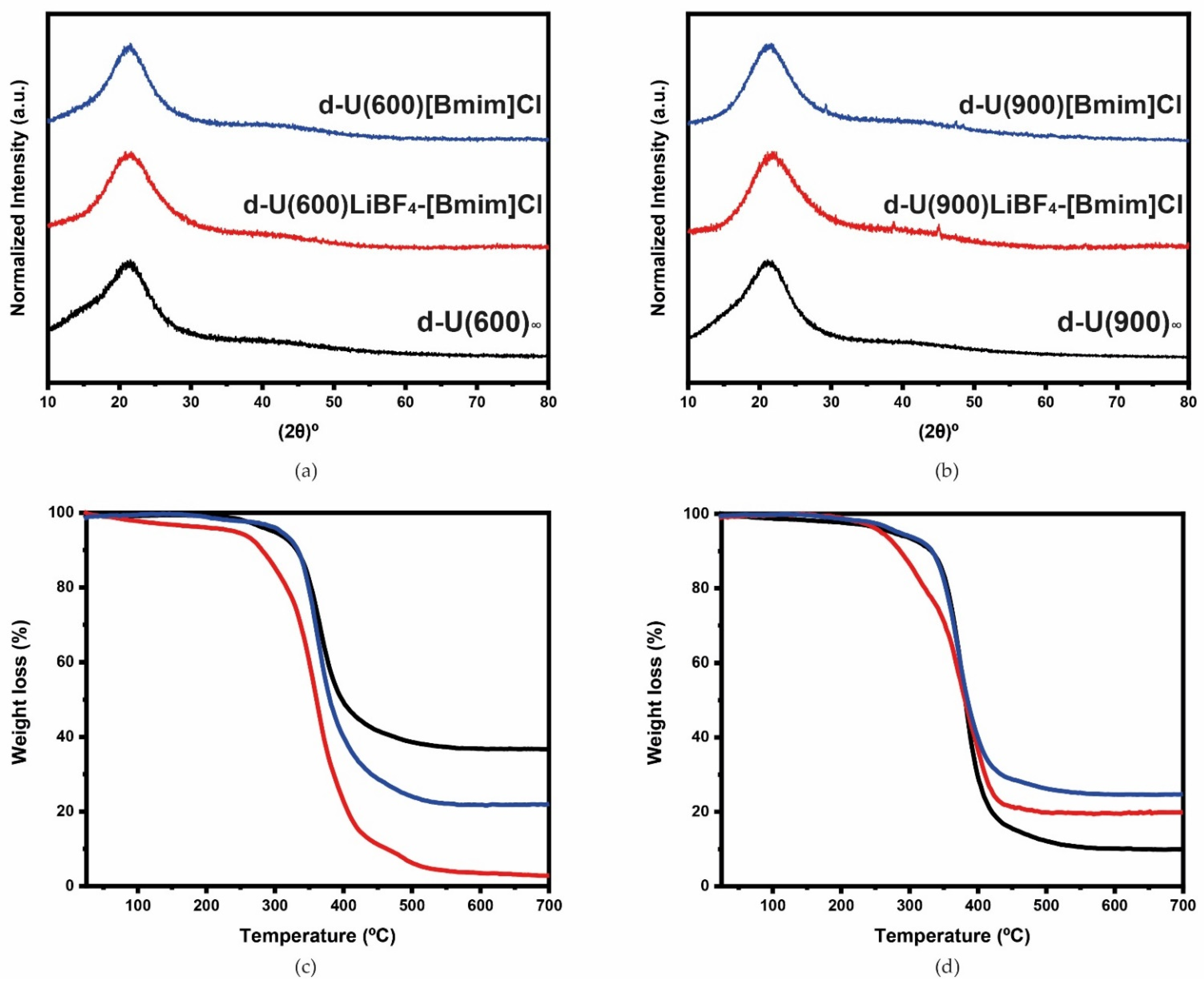
The XRD diffractograms and thermograms of d-U(600)LiBF4-[Bmim]Cl (red line, left side) and d-U(900)LiBF4-[Bmim]Cl (red line, right side) are presented in Figure 1a,c and Figure 1b,d, respectively. A broad band with a Gaussian shape, centered at around 21°, is seen in all of the XRD diffractograms (Figure 1a,b), and it is connected to the coherent diffraction of the siliceous domains [30].
Figure 1c shows that after the beginning of the analysis d-U(600)LiBF4-[Bmim]Cl started the degradation; 6% of the initial weight was lost by xerogel between room temperature and 250 °C. The plateau was achieved at 501 °C and at 700 °C about 3% of the initial mass remained to be decomposed (Figure 1c). The d-U(900)LiBF4-[Bmim]Cl (Figure 1d) is more stable than d-U(600)LiBF4-[Bmim]Cl. Below 204 °C the weight loss, less than 3%, was practically null. The decomposition was abrupt beyond this temperature and up to 454 °C. Between the latter temperature and 700 °C, about 20% of the sample remained to be decomposed. The thermal degradation for the non-doped materials (black line) is initiated at approximately 260 °C (Figure 1c,d). Those events confirm that the thermal stability of both hybrid electrolytes is adequate for application in ECDs.
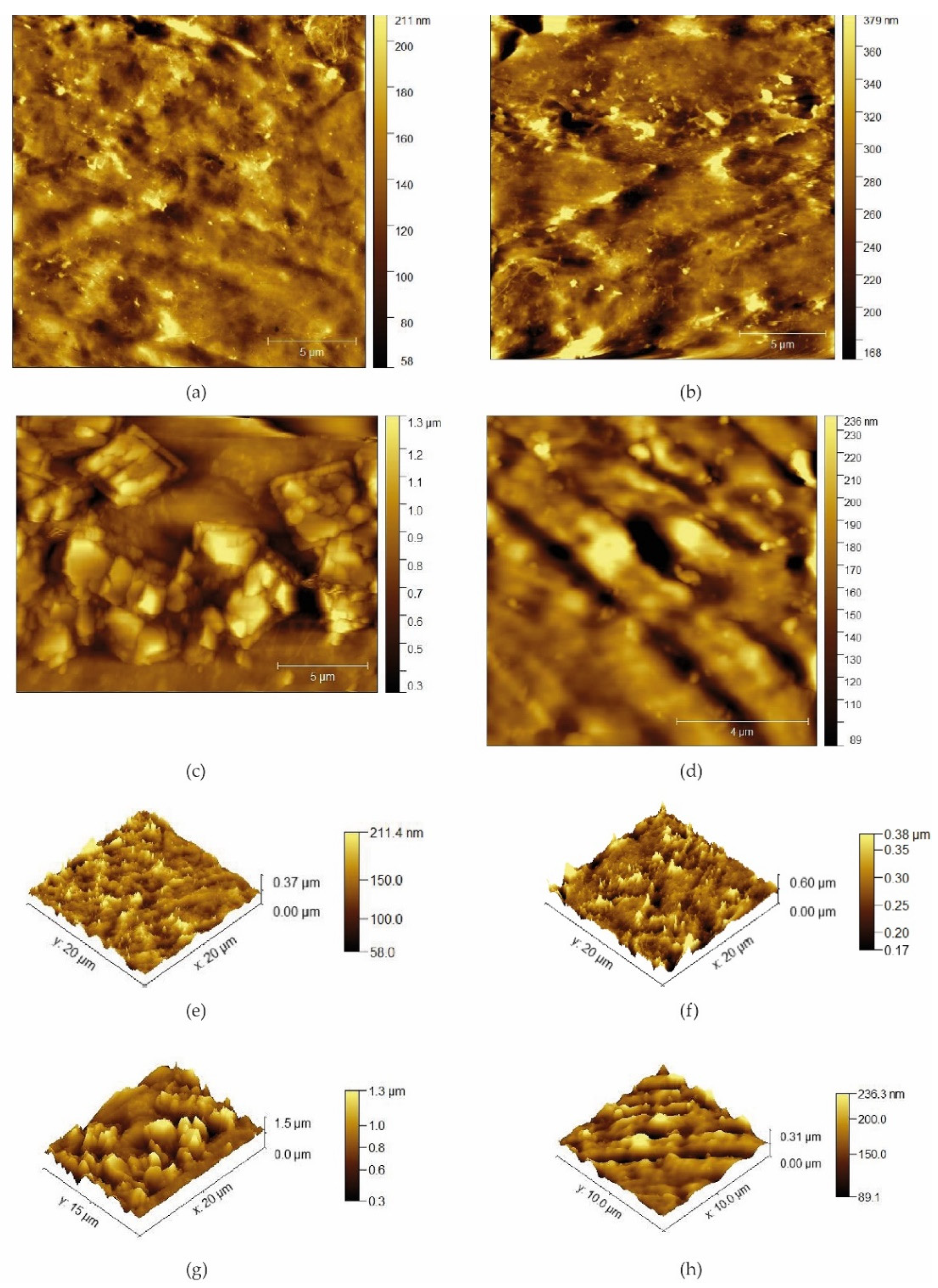
As pointed out by the difractograms, the electrolytes are essentially amorphous and the POM images revealed the same, exhibiting a minor proportion of anisotropic submicrometer domains, responsible for the birefringence observed (Figure S1a,b). To ascertain the influence of LiBF4 and [Bmim]Cl on the surface of the xerogels, the samples were examined by AFM (Figure 2c,d). As shown in Figure 2d and Table S2, the addition of the doping agents did not have any influence on the roughness of d-U(900)LiBF4-[Bmim]Cl, which did not happen in the d-U(600) electrolyte (Figure 2c). The surface in contact with the air was used to perform the analysis in order to avoid the small defects and patterns that mimic the imperfections on the mold.
The water contact angle values evaluated in static mode for d-U(600) and d-U(900) were 50.64 ± 24.08° and 61.36 ± 13.30° (Figure 3a,b—black symbols). These values reveal the hydrophilic behavior of both samples. The values obtained for d-U(600)LiBF4-[Bmim]Cl (97.29 ± 4.15°) (Figure 3a—red symbols) and d-U(900)LiBF4-[Bmim]Cl (95.1 ± 5.01°) (Figure 3b—red symbols) indicate that the incorporation of [Bmim]Cl and LiBF4 promotes an increase in the hydrophobicity of the films. This finding is somehow interesting, considering that [Bmim]Cl has a hygroscopic character.
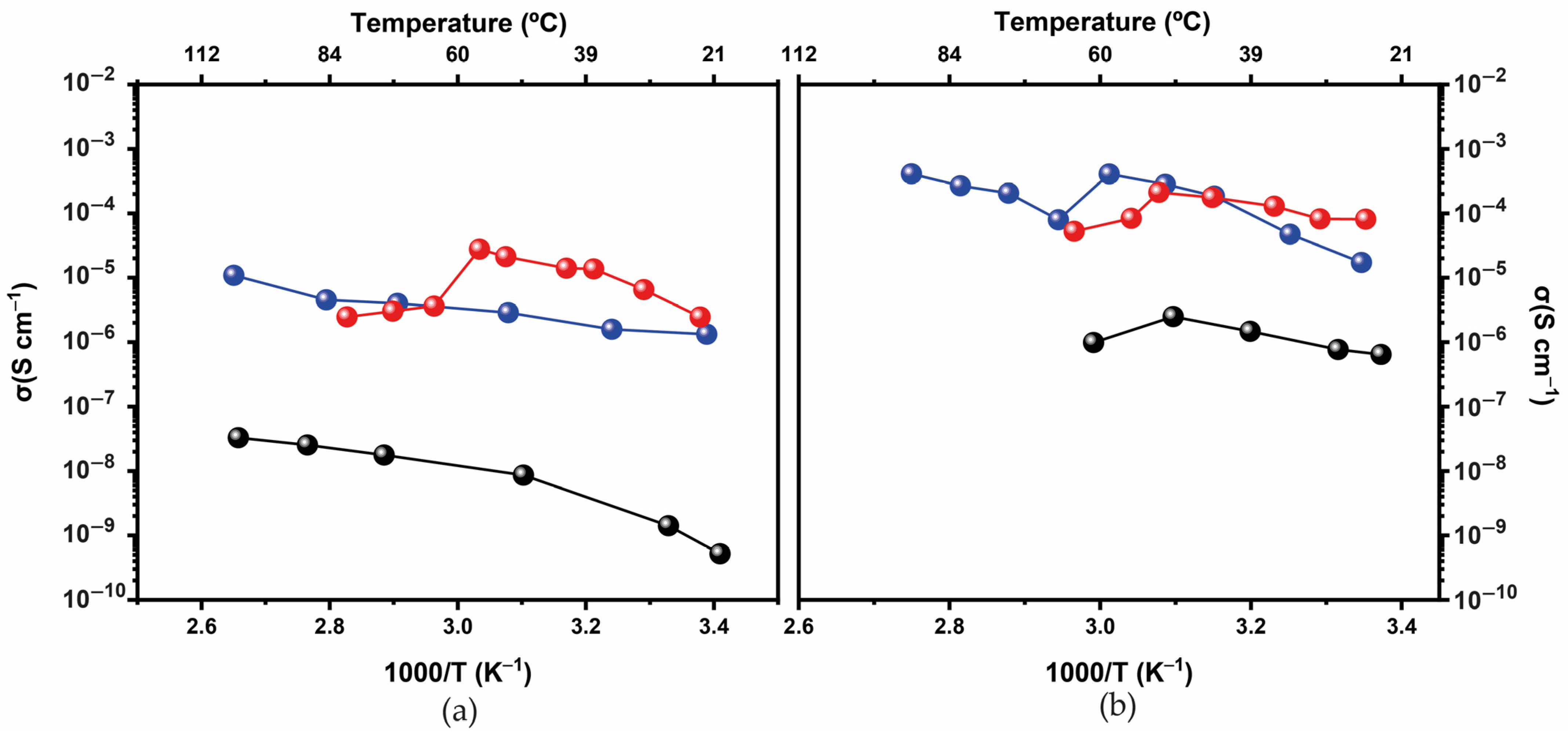
Figure 4a shows the Arrhenius conductivity plot of d-U(600), d-U(600)[Bmim]Cl and d-U(600)LiBF4-[Bmim]Cl. As usual over the whole range of temperatures studied, the doped systems exhibit values for ionic conductivity higher than the non-doped matrix. A non-linear behavior, typical of amorphous materials, is observed at temperatures higher than 55 °C. For the d-U(900)LiBF4-[Bmim]Cl the ionic conductivity attained 2.45 × 10⁻⁶ at room temperature and 2.76 × 10⁻⁵ S·cm−1 at 50 °C (Figure 4a—red symbols). The values of d-U(600)[Bmim]Cl were one order of magnitude lower (Figure 4a—blue symbols).
The ionic conductivity of d-U(900)LiBF4-[Bmim]Cl (Figure 4b—red symbols) attained 8.10 × 10⁻⁵ at room temperature and 2.8 × 10⁻⁴ S·cm−1 at 55 °C. We can compare these results with those reported by Barbosa et al. [32] for the POEnLiBF4 system. The di-ureasils doped with LiBF4 and [Bmim]Cl exhibit the highest conductivity of the series of electrolytes reported in the literature [37,38]. The total ionic conductivity of both electrolyte systems is higher, in particular at lower temperatures. For instance, the higher molecular weight di-ureasils containing more oxyethylene chains are more conducting than ormolytes based on the di-ureasil structure d-U(600). The restrictions in polymer segment mobility and a decrease in the mobility of the guest ions are because d-U(600) segments are quite short. In this way, it is possible to presume that the combination of the lithium salt and the IL in the di-ureasil matrices was a success, as we managed to increase the conductivity more than when simply using a lithium salt. In the case of doping with LiBF4 and [Bmim]Cl a change, (around 60 °C for d-U(600) and around 50 °C for d-U(900) is detected, which leads to a conductivity decrease. This change can be associated with the viscosity associated with the concentration of the IL and LiBF4 mixture. Viscosity has a strong effect on the rate of mass transport and this is why it is a very important parameter in electrochemical studies [39]. The decrease in conductivity may be explained by the fact that the addition of Li+ ions to an IL raises the viscosity, promoting a strong interaction between the Li+ ions with the anions. Moreover, the [Bmim]+ ion can interact with the BF4- ion to form a cluster (triplet or multiplets).

3.2. Characterization of the ECDs

The ECDs were characterized by the electrochromic contrast (∆T = Tbleached − Tcolored, in %, at 555 nm, where T is transmittance in the bleached and colored state), the optical density change [∆(OD) = −log(Tcolored/Tbleached)], the coloration efficiency [where CE = ∆OD/∆Q, and ∆Q is the amount of charge necessary to produce the optical change (in C)], the cycling stability and the CIE L*a*b* color coordinates.
Both assembled ECDs (ECD1—assembled with the d-U(600)LiBF4-[Bmim]Cl electrolyte—and ECD2—assembled with the d-U(900)LiBF4-[Bmim]Cl electrolyte) were subjected to the same procedures: (1) −2.0/+2.0 V for six cycles; (2) −2.5/+2.5 V for six cycles; (3) −3.0/+3.0 V for six cycles (iv) −3.0/+3.0 V of 50 CA cycles (100 s/cycle). The spectra visible/NIR were registered previous and after each cycle (Figure 5a–c).
At 555 nm, the T value of the as-prepared ECD1 is 78%. This T value is progressively reduced up to 64, 56 and 47% upon the application of −2.0, −2.5 and −3.0 V, and the corresponding increase in the ∆T values is 8, 15 and 17% (Table 1). As a result, with an increase in voltage, the devices became progressively darker (Figure S1). The maximum performance was observed after the application of −3.0 V: ∆T = 17% (Table 1) and L* = 48.1 (Figure S2).
At 555 nm, a T value of 65% is observed on the as-prepared ECD2 (Figure 5c). With the voltage increase, a progressive reduction in the T value occurred too (Table 1).
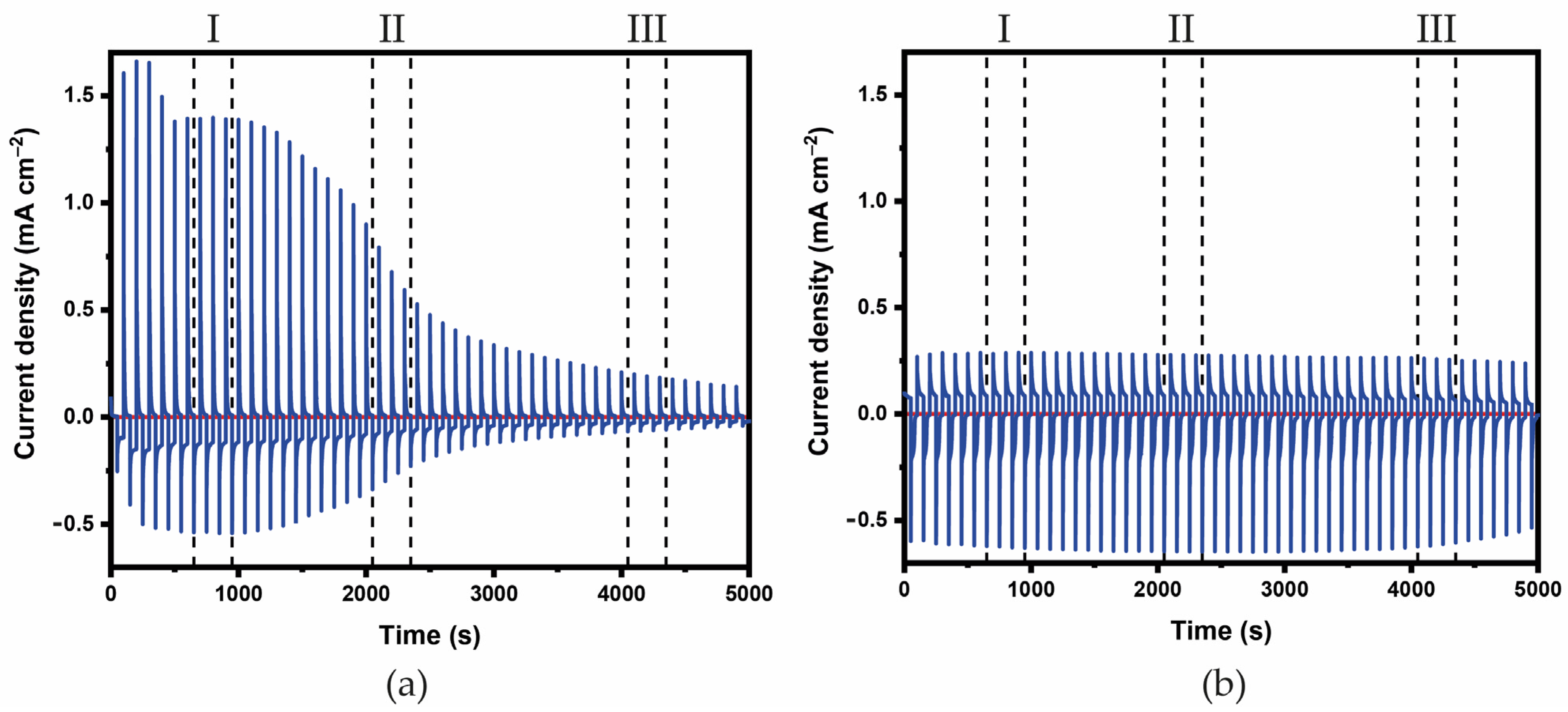
The ECDs present good cycling stability and reversibility (Figure 6). In the first cycles (seventh to ninth), the disinserted charge density values (Qout) of ECD2 were significantly lower than those of ECD1, as seen in Figure S3a,b. The CEin and CEout values of the two ECDs for different cycles of the CA are listed in Table 1.
Comparing the CEout values of ECD1 and ECD2, the former is significantly lower at the beginning of the CA study. However, in the final cycles, the values became very similar. The −CEin values of ECD1 are higher than those of ECD2. Both the ECDs included in this study present good coloration efficiency, relatively fast colored kinetics, and good cycling stability. This gives us an indication of interest for application in near future on smart windows.

4. Discussion

We introduce two new electrolytes synthesized by the sol-gel method incorporating a lithium salt and an IL. This is a follow-up to recent works from our group dedicated to the development of electrolytes with better characteristics for the next generation of smart windows for future zero-energy buildings [12,20,31]. The morphological, structural, thermal, and properties of the electrolytes were analyzed, and two ECDs containing the two electrolytes were tested.
The results are satisfactory and in particular, the ∆(OD) value is quite close to those of ECDs that had already been described in the literature (Table 1). Despite the high CE values produced by ECD2, these systems still need further improvements so that the response times are substantially decreased. Currently, the use of lithium salt and IL in natural host polymers that are affordable, available, and benign is being studied for use as electrolytes in ECDs [21].

Supplementary Materials

The following supporting information can be downloaded at: www.mdpi.com/article/10.3390/en16010426/s1; Table S1: Experimental details of the preparation of the di-ureasil ormolytes; Figure S1: POM (crossed polarizers) images of d-U(600)LiBF4[Bmim]Cl (a) and d-U(900)LiBF4[Bmim]Cl (b); Table S2. AFM roughness values of the d-U(600) and d-U(900)-based di-ureasil ormolytes; Figure S2. 1976 CIE L*a*b* color diagrams of the ECD1 (a) and ECD2 (b). Figure S3: Time intervals (s) at which the CE values were measured and calculated. Figure S4: Inserted (-Qin) (a) and de-inserted (Qout) (b) charge density.

Author Contributions

M.F.: conceptualization, methodology; P.J.N.: synthesis of the electrolytes, characterization via TGA, POM, XRD, AFM, CA measurements, assembly of the ECDs and organization of all data; R.F.P.P. and M.M.S.: complex impedance and cyclic voltammetry measurements of the electrolytes; S.P. and E.F.: deposition and characterization of the IZO, IZO/WO3 and IZO/NiO layers; P.J.N.: writing-original draft preparation; M.F. and V.d.Z.B.: writing-review and editing; all the authors: visualization; M.F. and V.d.Z.B.: supervision; V.d.Z.B.: project administration. All authors have read and agreed to the published version of the manuscript.

Funding

This work was funded by “SOLPOWINS—Solar-Powered Smart Windows for Sustainable Buildings” (PTDC/CTM-REF/4304/2020), OBTAIN-Objective Building Sustainability (NORTE-01-0145-FEDER-000084) projects, financed by the Foundation for Science and Technology (FCT) and FEDER, and NORTE2020, respectively, and by CQ-VR (UID/QUI/00616/2013 and UID/QUI/00616/2019) and by CQ-UM (UIDB/00686/2020 and UIDP/00686/2020). P.J. Nunes acknowledges CQ-VR/FCT for a grant (UI/BD/151084/2021). M.F. and R.F.P. Pereira acknowledge FCT-UTAD and FCT-UMinho for the contracts in the scope of Decreto-Lei 57/2016—Lei 57/2017, respectively.

Data Availability Statement

Data is contained within the article or supplementary material. The data presented in this study are available in [insert article or supplementary material here].

Acknowledgments

The authors acknowledge the Electron Microscopy Unit (UME) of UTAD for collecting the XRD data.

Conflicts of Interest

The authors declare no conflict of interest.

References

  1. Goal 11: Make Cities Inclusive Resilient and Sustainable. Available online: https://sdgs.un.org/goals/goal11 (accessed on 6 September 2022).
  2. Remarks to International Energy Agency Clean Energy Transition Summit. Available online: https://www.un.org/sg/en/content/sg/speeches/2020-07-09/remarks-international-energy-agency-clean-energy-transition-summit (accessed on 6 September 2022).
  3. Granqvist, C.G.; Arvizu, M.A.; Bayrak Pehlivan, İ.; Qu, H.-Y.; Wen, R.-T.; Niklasson, G.A. Electrochromic Materials and Devices for Energy Efficiency and Human Comfort in Buildings: A Critical Review. Electrochim. Acta 2018, 259, 1170–1182. [Google Scholar] [CrossRef] [Green Version]
  4. Barbosa, P.C.; Silva, M.M.; Smith, M.J.; Gonçalves, A.; Fortunato, E.; Nunes, S.C.; de Zea Bermudez, V. Di-Ureasil Xerogels Containing Lithium Bis(Trifluoromethanesulfonyl)Imide for Application in Solid-State Electrochromic Devices. Electrochim. Acta 2009, 54, 1002–1009. [Google Scholar] [CrossRef] [Green Version]
  5. Rosseinsky, D.R.; Mortimer, R.J. Electrochromic Systems and the Prospects for Devices. Adv. Mater. 2001, 13, 783–793. [Google Scholar] [CrossRef]
  6. Kim, J.; Ong, G.K.; Wang, Y.; LeBlanc, G.; Williams, T.E.; Mattox, T.M.; Helms, B.A.; Milliron, D.J. Nanocomposite Architecture for Rapid, Spectrally-Selective Electrochromic Modulation of Solar Transmittance. Nano Lett. 2015, 15, 5574–5579. [Google Scholar] [CrossRef] [Green Version]
  7. Llordés, A.; Garcia, G.; Gazquez, J.; Milliron, D.J. Tunable Near-Infrared and Visible-Light Transmittance in Nanocrystal-in-Glass Composites. Nature 2013, 500, 323–326. [Google Scholar] [CrossRef] [Green Version]
  8. DeForest, N.; Shehabi, A.; O’Donnell, J.; Garcia, G.; Greenblatt, J.; Lee, E.S.; Selkowitz, S.; Milliron, D.J. United States Energy and CO2 Savings Potential from Deployment of Near-Infrared Electrochromic Window Glazings. Build. Environ. 2015, 89, 107–117. [Google Scholar] [CrossRef] [Green Version]
  9. Casini, M. Active Dynamic Windows for Buildings: A Review. Renew. Energy 2018, 119, 923–934. [Google Scholar] [CrossRef]
  10. Calnan, S.; Tiwari, A.N. High Mobility Transparent Conducting Oxides for Thin Film Solar Cells. Thin Solid Films 2010, 518, 1839–1849. [Google Scholar] [CrossRef]
  11. Gonçalves, M.C.; Pereira, R.F.P.; Alves, R.; Nunes, S.C.; Fernandes, M.; Gonçalves, H.M.R.; Pereira, S.; Silva, M.M.; Fortunato, E.; Rego, R.; et al. Electrochromic Device Composed of a Di-Urethanesil Electrolyte Incorporating Lithium Triflate and 1-Butyl-3-Methylimidazolium Chloride. Front. Mater. 2020, 7, 139. [Google Scholar] [CrossRef]
  12. Cardoso, M.A.; Pereira, R.F.P.; Pereira, S.; Gonçalves, H.; Silva, M.M.; Carlos, L.D.; Nunes, S.C.; Fortunato, E.; Ferreira, R.A.S.; Rego, R.; et al. Three-Mode Modulation Electrochromic Device with High Energy Efficiency for Windows of Buildings Located in Continental Climatic Regions. Adv. Sustain. Syst. 2019, 3, 1800115. [Google Scholar] [CrossRef]
  13. Fernandes, M.; Freitas, V.; Pereira, S.; Leones, R.; Silva, M.M.; Carlos, L.D.; Fortunato, E.; Ferreira, R.A.S.; Rego, R.; Bermudez, V.D.Z. Luminescent Electrochromic Devices for Smart Windows of Energy-Efficient Buildings. Energies 2018, 11, 3513. [Google Scholar] [CrossRef] [Green Version]
  14. Nunes, S.C.; de Zea Bermudez, V.; Silva, M.M.; Smith, M.J.; Ostrovskii, D.; Sá Ferreira, R.A.; Carlos, L.D.; Rocha, J.; Gonçalves, A.; Fortunato, E. Sol–Gel-Derived Potassium-Based Di-Ureasils for “Smart Windows”. J. Mater. Chem. 2007, 17, 4239. [Google Scholar] [CrossRef] [Green Version]
  15. Fernandes, M.; Rodrigues, L.C.; Ferreira, R.A.S.; Gonçalves, A.; Fortunato, E.; Silva, M.M.; Smith, M.J.; Carlos, L.D.; de Zea Bermudez, V. K+-Doped Poly(ε-Caprolactone)/Siloxane Biohybrid Electrolytes for Electrochromic Devices. Solid State Ionics 2011, 204–205, 129–139. [Google Scholar] [CrossRef] [Green Version]
  16. Fernandes, M.; Leones, R.; Pereira, S.; Costa, A.M.S.; Mano, J.F.; Silva, M.M.; Fortunato, E.; de Zea Bermudez, V.; Rego, R. Eco-Friendly Sol-Gel Derived Sodium-Based Ormolytes for Electrochromic Devices. Electrochim. Acta 2017, 232, 484–494. [Google Scholar] [CrossRef]
  17. Pereira, R.F.P.; Sentanin, F.; Pawlicka, A.; Gonçalves, M.C.; Silva, M.M.; de Zea Bermudez, V. Smart Windows Prepared from Bombyx Mori Silk. ChemElectroChem 2016, 3, 1084–1097. [Google Scholar] [CrossRef]
  18. Nunes, S.C.; Saraiva, S.M.; Pereira, R.F.P.; Pereira, S.; Silva, M.M.; Carlos, L.D.; Fortunato, E.; Ferreira, R.A.S.; Rego, R.; de Zea Bermudez, V. Sustainable Dual-Mode Smart Windows for Energy-Efficient Buildings. ACS Appl. Energy Mater. 2019, 2, 1951–1960. [Google Scholar] [CrossRef]
  19. Alves, R.; Sentanin, F.; Sabadini, R.C.; Fernandes, M.; de Zea Bermudez, V.; Pawlicka, A.; Silva, M.M. Samarium (III) Triflate-Doped Chitosan Electrolyte for Solid State Electrochromic Devices. Electrochim. Acta 2018, 267, 51–62. [Google Scholar] [CrossRef]
  20. Barbosa, P.C.; Fernandes, M.; Silva, M.M.; Smith, M.J.; Vilela, S.M.F.; Gonçalves, A.; Olveira, M.C.; Fortunato, E.; Rego, R.; Zea Bermudez, V.d. Di-Ureasil Hybrids Doped with LiBF4: Attractive Candidates as Electrolytes for “Smart Windows”. Int. J. Electrochem. Sci. 2011, 6. Available online: https://hdl.handle.net/1822/13611 (accessed on 6 September 2022).
  21. Fernandes, M.; Leones, R.; Costa, A.M.S.; Silva, M.M.; Pereira, S.; Mano, J.F.; Fortunato, E.; Rego, R.; de Zea Bermudez, V. Electrochromic Devices Incorporating Biohybrid Electrolytes Doped with a Lithium Salt, an Ionic Liquid or a Mixture of Both. Electrochim. Acta 2015, 161, 226–235. [Google Scholar] [CrossRef]
  22. Watanabe, M.; Thomas, M.L.; Zhang, S.; Ueno, K.; Yasuda, T.; Dokko, K. Application of Ionic Liquids to Energy Storage and Conversion Materials and Devices. Chem. Rev. 2017, 117, 7190–7239. [Google Scholar] [CrossRef] [Green Version]
  23. Ohno, H. Electrochemical Aspects of Ionic Liquids; Ohno, H., Ed.; John Wiley & Sons Inc.: Hoboken, NJ, USA, 2005. [Google Scholar] [CrossRef]
  24. Ohno, H. Functional Design of Ionic Liquids. Bull. Chem. Soc. Jpn. 2006, 79, 1665–1680. [Google Scholar] [CrossRef]
  25. Lu, W.; Fadeev, A.G.; Qi, B.; Smela, E.; Mattes, B.R.; Ding, J.; Spinks, G.M.; Mazurkiewicz, J.; Zhou, D.; Wallace, G.G.; et al. Use of Ionic Liquids for π-Conjugated Polymer Electrochemical Devices. Science 2002, 297, 983–987. [Google Scholar] [CrossRef] [PubMed] [Green Version]
  26. Bircan, H.; Seshadri, V.; Padilla, J.; Invernale, M.; Otero, T.F.; Sotzing, G.A. Use of Polymer/Ionic Liquid Plasticizers as Gel Electrolytes in Electrochromic Devices. J. Phys. Conf. Ser. 2008, 127, 012011. [Google Scholar] [CrossRef]
  27. Pozo-Gonzalo, C.; Mecerreyes, D.; Pomposo, J.A.; Salsamendi, M.; Marcilla, R.; Grande, H.; Vergaz, R.; Barrios, D.; Sánchez-Pena, J.M. All-Plastic Electrochromic Devices Based on PEDOT as Switchable Optical Attenuator in the near IR. Sol. Energy Mater. Sol. Cells 2008, 92, 101–106. [Google Scholar] [CrossRef]
  28. Marcilla, R.; Alcaide, F.; Sardon, H.; Pomposo, J.A.; Pozo-Gonzalo, C.; Mecerreyes, D. Tailor-Made Polymer Electrolytes Based upon Ionic Liquids and Their Application in All-Plastic Electrochromic Devices. Electrochem. Commun. 2006, 8, 482–488. [Google Scholar] [CrossRef]
  29. Galiński, M.; Lewandowski, A.; Stępniak, I. Ionic Liquids as Electrolytes. Electrochim. Acta 2006, 51, 5567–5580. [Google Scholar] [CrossRef]
  30. Carlos, L.D.; de Zea Bermudez, V.; Sá Ferreira, R.A.; Marques, L.; Assunção, M. Sol−Gel Derived Urea Cross-Linked Organically Modified Silicates. 2. Blue-Light Emission. Chem. Mater. 1999, 11, 581–588. [Google Scholar] [CrossRef]
  31. de Zea Bermudez, V.; Carlos, L.; Duarte, M.; Silva, M.; Silva, C.J.; Smith, M.; Assunção, M.; Alcácer, L. A Novel Class of Luminescent Polymers Obtained by the Sol–Gel Approach. J. Alloys Compd. 1998, 275–277, 21–26. [Google Scholar] [CrossRef]
  32. Barbosa, P.; Rodrigues, L.; Silva, M.; Smith, M.; Gonçalves, A.; Fortunato, E. Application of Di-Ureasil Ormolytes Based on Lithium Tetrafluoroborate in Solid-State Electrochromic Displays. J. Mater. Chem. 2010, 20, 723–730. [Google Scholar] [CrossRef]
  33. Fujita, K.; Nakano, R.; Nakaba, R.; Nakamura, N.; Ohno, H. Hydrated Ionic Liquids Enable Both Solubilisation and Refolding of Aggregated Concanavalin A. Chem. Commun. 2019, 55, 3578–3581. [Google Scholar] [CrossRef]
  34. Silva, M.M.; Nunes, S.C.; Barbosa, P.C.; Evans, A.; de Zea Bermudez, V.; Smith, M.J.; Ostrovskii, D. Sol–Gel Preparation of a Di-Ureasil Electrolyte Doped with Lithium Perchlorate. Electrochim. Acta 2006, 52, 1542–1548. [Google Scholar] [CrossRef] [Green Version]
  35. Nunes, S.C.; de Zea Bermudez, V.; Ostrovskii, D.; Silva, M.M.; Barros, S.; Smith, M.J.; Carlos, L.D.; Rocha, J.; Morales, E. Diurea Cross-Linked Poly(Oxyethylene)/Siloxane Ormolytes for Lithium Batteries. J. Electrochem. Soc. 2005, 152, A429. [Google Scholar] [CrossRef] [Green Version]
  36. Fortunato, E.; Pimentel, A.; Gonçalves, A.; Marques, A.; Martins, R. High Mobility Amorphous/Nanocrystalline Indium Zinc Oxide Deposited at Room Temperature. Thin Solid Films 2006, 502, 104–107. [Google Scholar] [CrossRef]
  37. Barbosa, P.C.; Silva, M.M.; Smith, M.J.; Gonçalves, A.; Fortunato, E. Studies of Solid-State Electrochromic Devices Based on PEO/Siliceous Hybrids Doped with Lithium Perchlorate. Electrochim. Acta 2007, 52, 2938–2943. [Google Scholar] [CrossRef] [Green Version]
  38. Barbosa, P.C.; Rodrigues, L.C.; Silva, M.M.; Smith, M.J. Preparation of Hybrid Organic–Inorganic Materials Based on a Di-Ureasil Matrix Doped with Lithium Bis(Trifluoromethanesulfonyl)Imide. J. Power Sources 2008, 180, 607–611. [Google Scholar] [CrossRef] [Green Version]
  39. Monteiro, M.J.; Bazito, F.F.C.; Siqueira, L.J.A.; Ribeiro, M.C.C.; Torresi, R.M. Transport Coefficients, Raman Spectroscopy, and Computer Simulation of Lithium Salt Solutions in an Ionic Liquid. J. Phys. Chem. B 2008, 112, 2102–2109. [Google Scholar] [CrossRef]
Scheme 1. (A). Composition of the prototype glass/IZO/a-WO3/IC/c-NiO/IZO/glass ECD. (B). Electrolyte composition. (C). 3D-topographical AFM images of (a) TCO/EC1 and (b) TCO/EC2.
Energies 16 00426 sch001
Figure 1. Diffractograms (a,b) and thermograms (c,d) of the d-U(600) and d-(900)-based electrolytes. Non-doped materials (black line), materials doped with LiBF4 and [Bmim]Cl (red line) and materials doped solely [Bmim]Cl (blue line).
Energies 16 00426 g001
Figure 2. Topographical AFM images of d-U(600) (a,e), d-U(900) (b,f), d-U(600)LiBF4-[Bmim]Cl (c,g) and d-U(900)LiBF4-[Bmim]Cl (d,h).
Energies 16 00426 g002
Figure 3. Water contact angle, in static mode, of d-U(600) (a) and d-(900) (b) based di-ureasils. Non-doped materials (black symbols), materials doped doping with LiBF4 and [Bmim]Cl (red symbols) and materials doped solely with [Bmim]Cl (blue symbols).
Energies 16 00426 g003
Figure 4. Ionic conductivity of d-U(600) (a) and d-(900)- (b) based di-ureasils. Non-doped materials (black symbols), materials doped with LiBF4 and [Bmim]Cl (red symbols) and materials doped solely with [Bmim]Cl (blue symbols).
Energies 16 00426 g004
Figure 5. Transmission spectra in the 400–1000 nm regions of the ECD1 (a) and ECD2 (c) devices. Representative images of the ECDs (b) colored states [semi-bright mode (−2.0 V, green solid line)], dark mode (−3.0 V, blue solid line) and the bleached state [corresponding dotted lines, bright mode].
Energies 16 00426 g005
Figure 6. Current density (mA·cm−2) as a function of time (s) for the ECD1 (a) and ECD2 (b) The voltage steps applied up to ±3.0 V. The dashed lines are the time intervals at which the CE values were measured and calculated. Figure S4 shows a zoom of these values.
Energies 16 00426 g006
Table 1. Parameters for ECDs characterization.
Hybrid Di-Ureasil HostDoping AgentVoltage (V)∆T555 nm (%)∆(OD)555 nmCA Interval 1CEinCEoutReferences
(cm2·C−1)
d-U(600)LiBF4-[Bmim]Cl−2.0/+2.07.90.05
−2.5/+2.514.60.10 ECD1
−3.0/+3.016.50.13I−88.02+25.66This work
II−110.469+43.98
III−420.621+111.40
d-U(900)LiBF4-[Bmim]Cl−2.0/+2.0
−2.5/+2.5
7.8
16.3
0.05
0.12
ECD2
I−26.609+91.90This work
−3.0/+3.019.10.15II−27.272+115.13
III−39.236+90.35
d-U(900)LiBF4−1.5/+6.518.80.11 [32]
d-U(2000)LiBF4−4.0/+4.0180.13 [20]
d-U(2000)[BIm][TfO] 2−2.0/+3.0330.28 [12]
1 CA interval examined, see Figure 6. 2 1-butylimidazolium trifluoromethanesulfonate proton IL
Disclaimer/Publisher’s Note: The statements, opinions and data contained in all publications are solely those of the individual author(s) and contributor(s) and not of MDPI and/or the editor(s). MDPI and/or the editor(s) disclaim responsibility for any injury to people or property resulting from any ideas, methods, instructions or products referred to in the content.