Article

Experimental Investigation on the Noise Characteristics of a Squirrel-Cage Fan with Different Blade Lengths

1
School of Aeronautical Engineering, Taizhou University, Taizhou 318000, China
2
Zhejiang Yilida Ventilator Co., Ltd., Taizhou 318056, China
3
College of Electric and Information Engineering, Henan University of Science and Technology, Luoyang 471023, China
4
National-Provincial Joint Engineering Laboratory for Fluid Transmission System Technology, Zhejiang Sci-Tech University, Hangzhou 310018, China
*
Author to whom correspondence should be addressed.
Energies 2023, 16(1), 69; https://doi.org/10.3390/en16010069
Submission received: 23 October 2022 / Revised: 1 December 2022 / Accepted: 16 December 2022 / Published: 21 December 2022

Abstract

:
Squirrel-cage fans are widely applied in air conditioning systems, and their aerodynamic noise mainly related to blade length. The aerodynamic performance and noise spectrum of squirrel-cage fans are synchronously measured in an anechoic wind tunnel. The effect of blade lengths and different geometric configurations on the noise of a squirrel-cage fan is experimentally investigated. This paper focuses on the total sound pressure level and noise spectrum characteristics at different measurement points. Noise distributions of the outlet of the forward squirrel-cage fan exhibited axial-symmetry and large differences for those of vertical direction. In lower fan positions, the noise was greater than that of the top. In particular, it was found that blades were easy to generate higher noise when their length was reduced by 31.7%. The findings suggest that the broadband noise of the squirrel-cage fan should be fully considered for noise reduction. The purpose of this work is to provide a novelty reference for the low-cost modification method of cutting blades. The results show that fans with shorter blades have lower noise and kept an excellent performance. These finding have implications for fan manufacturers.

1. Introduction

The squirrel-cage fan is a kind of centrifugal fan with forward-curved blades. Generally, they are applied in air conditioning systems due to their smaller size and lower noise [1]. Squirrel-cage fan noise mainly consists of tone noise and broadband noise. Tone noise is primarily related to the interference between the blade and the volute tongue. Velarde [2] concluded that the blade-passing frequency (BPF) is dominant in the noise spectra, and tone noise decreases with the decreased flow rate. Sasaki [3] proved that the influence of the Karman vortex street on the noise of high and low frequencies does not occur, corresponding to the broadband noise. Mahmoodi et al. [4] noted that the tone noise increases as flow rate increases, while the fan with double outlets has a higher BPF noise at all working points. Petricelli [5] experimentally studied the effect of inflow distortions of propeller noise; the study documented that the presence of non-uniformity in the flow results in an increase in the sound pressure levels of the interaction tones compared to the configuration without any inflow distortion. Li et al. [6] discussed the pressure pulsations and three-dimensional vortices within the model pump. They stated that the vortex street is generated at the diffuser trailing edge as indicated by the alternate shedding of positive and negative vortices, and the horseshoe vortex is captured within the wake flow.
Therefore, the most effective method of noise reduction is optimizing the blade profile. Velarde [7] stated that it is to slightly reduce the height of the fan-outlet section combined with a bend of the volute tongue, resulting in the decreasing fan-noise generation without reducing the operating range. Mao et al. [8] used the acoustic boundary element method to predict the sound field. They found that noise is generated by the rotating blades passing through the volute, and the volute changes the direction of sound. Lu et al. [9] optimized the volute of a squirrel-cage fan to reduce its vibration intensity and noise. Hao et al. [10] obtained that the properly inclined volute tongue has positive performance features in comparison with the baseline model and controls the broadband noise of a single-inlet centrifugal fan.
Meanwhile, it is also very important to reduce broadband noise. Rozenberg [11] improved the model of the trailing-edge noise of the blade and used advanced sensors to collect pressure–pulsation data at the trailing edge of the blade. The predicted results are in good agreement with the experimental results but fail to provide a general theoretical conclusion. Because the core parameters needed for the prediction are mainly obtained from experiments with wall-pressure sensors, this proves that broadband noise is predominantly caused by blade vortex, in which vortex fills the entire impeller leading to influence on the inlet and outlet of the fan [12]. Scheit [13] proposed that the efficiency and noise of a squirrel-cage fan can be made a better balance by adjusting the blade wrap angle, but the quantitative relationship between the wrap angle and fan noise was not provided. Wen et al. [14] found that the elliptical inlet nozzle can reduce the flow loss before the fluid enters the impeller channel as a result of the improvement of the aerodynamic and acoustic performance of the squirrel-cage fan. It is an effective way to improve efficiency and reduce noise by means of optimizing the blade structure [15]. Bauer et al. [16] experimentally studied the counter-rotating open rotor and drilled the leaf surface from the trailing edge to the middle of the blade. A modified non-dominated sorting-genetic algorithm coupled with a three-dimensional Reynolds-averaged Navier–Stokes computation is applied to get the optimum blade shape of a squirrel-cage fan [17].
As mentioned above, the fan experiments of noise and aerodynamic characteristics can be performed separately. The aerodynamic performance of the fan is measured in an air chamber, and then the noise is measured in another anechoic chamber since the air chamber is difficult to be built in the anechoic chamber. In this research, the aerodynamic performance and noise of some squirrel-cage fans were measured synchronously in a laboratory to study the effect of blade length on the noise and efficiency of the fan. Moreover, total sound pressure level and frequency spectra at each point of the fan inlet and outlet under different flow rates and rotating speeds are analyzed.

2. Parameters of the Original Fan and Modification of Blades
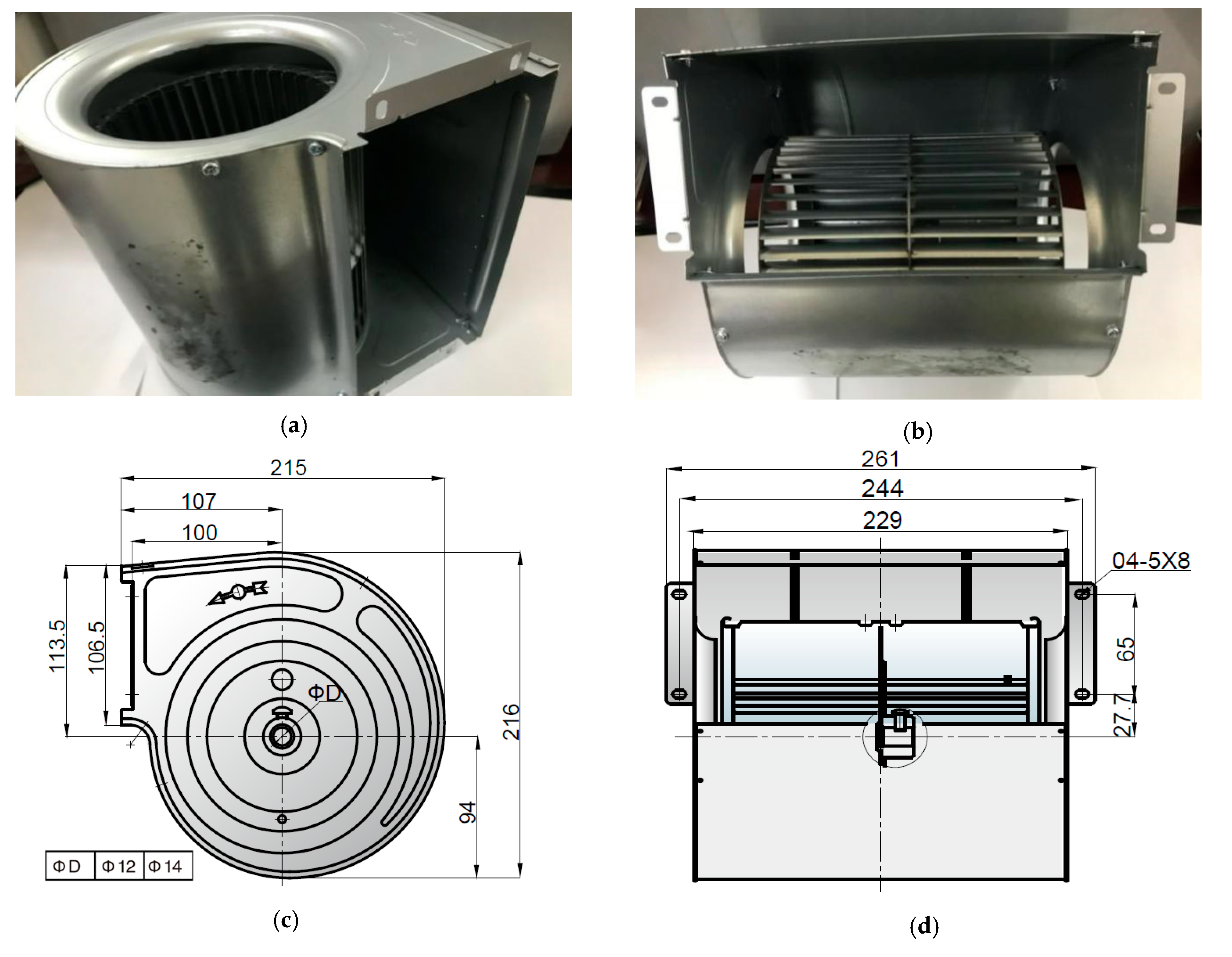
As shown in Figure 1, the squirrel-cage fan includes a volute, a volute tongue, and an impeller with 40 blades. Table 1 shows the main parameters.
During the process of manufacture, the squirrel-cage fan is always made some simple modifications to meet the requirements of noise reduction with a minimum cost, such as changing the number of blades or cutting the length of blades. If the blade angle is also considered, the mold has to be adjusted as a result of higher expense. Figure 2a shows the three blades with different lengths. The axial length and radius curvature of the impeller blades remain unchanged, and the radial length based on the B blade is extended or shortened to obtain C and A blades, respectively. The lengths of the three blades are set to 8.97 mm (A), 10.90 mm (B), and 15.95 mm (C), respectively.
Figure 2b shows the two impellers installed with A and C blades. In addition to the different arc lengths of blades, the widths of the wheel hubs are slightly different. A nondimensionalized analysis is utilized by means of pressure and flow coefficients [18] to describe the experimental results;
ψ = P s t 1 2 ρ u 2 2
φ = Q m π 4 D 2 2 u 2
where ψ is the pressure coefficient, φ the flow coefficient, D2 the outlet diameter of the impeller, u2 the outlet velocity of the impeller, Qm is volume flow, and Pst is the pressure difference between inlet and outlet, and ρ is the air density.

3. Synchronous Experiments

3.1. Aerodynamic Test

The synchronous experiments with the semi-anechoic method to test noise and aerodynamic performance were carried out, as shown in Figure 3. It was designed to meet the standard of ISO5801, and the semi-anechoic noise test was conducted by ISO3745. Impeller diameters of the tested fan were from 40 mm to 1250 mm, and the flow ranged from 30 m3/h to 44,000 m3/h. Maximum static pressure can be 2500 Pa with the noise frequency from 50 to 20,000 Hz. The background noise in the laboratory was 12 dB(A). Figure 3 shows the experimental system and the instructions for key equipment. The semi-anechoic room is divided into two air chambers to measure the static pressure and noise of the tested fan.
The flow rate of the fan can be calculated based on the pressure differences before and after the nozzles. Figure 4 shows the details in the air chamber. Four pressure-measuring points were installed on the two-side walls, the top wall, and the ground in the air chamber, respectively. The flow rate was controlled by the nozzle and the static pressure was measured by the FC0332 pressure transmitter, and the rotating speed of the fan was measured by a ROLS-P laser tachometer. The expression of the A-weighted sound level was obtained by the following equation:
L A = 10 lg i = 1 8 10 0.1 ( L pi + Δ A i )
which Ai denotes the value of A sound level weighting. The unit of the A-weighted sound level LA is dB(A).
The maximum speed of this fan is set to around 1300 revolutions per minute (rpm). The impeller broke up in the destructive experiment under the damage parameter around 3500 rpm. Figure 5 shows the aerodynamic performance of the fan with three different blades under the condition of 1000 rpm and 1300 rpm, respectively. At 1000 rpm, their pressure coefficients and efficiencies are very closely under the minimum-flow rate. As the flow rate increased, pressure coefficients and efficiencies of A blade fan decreased significantly. For B blade and C blade fans at 1000 rpm with different flow coefficients, pressure coefficients reached up to 1.0 and pressure efficiencies were greater than 0.4. At the condition of 1300 rpm, the pressure coefficients of B blade and C blade fans were larger than 1.5. Similar trends for shorter blade fans could be observed at the condition of 1000 rpm. The results show that fans with shorter blades have lower efficiency. In this case, the B blade and C blade fans maintained a similar efficiency at 1000 rpm, but the efficiency of the A blade fan was too low. Therefore, it is applicable and doable for the proposed cutting blade strategy with controllable cutting length.

3.2. Noise Test

MPA201 microphones were applied for the noise test. The noise frequency range was from 20 Hz to 20,000 Hz, and the noise test range was from 16 dB(A) to 134 dB(A). The sound energy of fans in this paper is fundamentally changed from 0 Hz to 3 KHz, so we set up the 5 kHz for the upper boundary. Each microphone was calibrated to ensure reliability during the test. The microphone calibration instrument is a BK4228 generator and the recording time of the microphones was ten seconds.
Figure 6 shows the scheme of measuring points, including eight measuring points near the fan outlet. In Figure 6a, the outlet measurement points were located on a plane perpendicular to the ground, which was one meter from the fan outlet. Eight points were given as in a circle (see Figure 6b,c), and the distance from the measuring points to the center of the circle was one meter. In Figure 6d,e, five points are distributed semi-circularly at the noise measurement plane near the outlet located on the same horizontal plane. The length of point 11 is one meter from the center of motor, and length of the rest four points near the fan inlet is one meter starting from the center of the fan. Slight motor noise can be neglected in this case.
Figure 7 displays the distribution of the outlet noise of the C blade model at different flow rates at 1000 rpm, where 0 degrees represents point 1, 90 degrees is point 3, and 180 degrees is point 5. As the flow rate increased, both noises near the outlet and inlet for the C blade fan increased. The left and right distributions exhibited symmetrically, and the upper and lower noises were different. The value of point 5 was significantly greater than in point 1. It can be explained that the volute tongue generated the downwards airflow at the fan outlet leading to a larger velocity to generate a large noise. It implies that the direction of the outlet airflow make a great effect on the fan noise.

4. Characteristics Analysis of Noises

This section is to analyze the noise characteristics of the fan at different measuring points with different blade lengths. The rotating speeds of 1000 rpm for a flow rate of 0.132 m3/s and 0.204 m3/s correspond to the blade passing frequency of 666.7 Hz. Those fan noises on 1300 rpm for 0.12 m3/s and 0.216 m3/s were characterized by the blade passing a frequency of 866.7 Hz.
Figure 8 gives the outlet noise under different flow rates with two rotating speeds. Where 0 degrees represents measuring point 1, 45 degrees is point 2, and so forth. We can see that all distributions exhibited symmetry. Those of lower positions are higher noise because of the larger downward velocity on the fan outlet, which are closely related to the vortex at the volute outlet, as described in the paper [12]. Higher rotating speed generates larger noise as a result of the narrow noise gap between the C blade and B blade fans. However, compared to B and C blade fans, the outlet noise of A blade is highest at the same rotating speeds and flow rates.
Figure 9 gives the inlet noise at similar flow rates of different blade models with different rotating speeds, where 90 degrees represents measuring point 9, 45 degrees is for measuring point 10, 0 degrees is for measuring point 11, 135 degrees is for measuring point 13, and 180 degrees is for measuring point 12. At the same flow rates, the noise at point 9 is the smallest, and point 13 is the largest, with a fluctuation of 7.0 dB(A). This is related to the obstruction of the motor and the further distance of the measuring point from the fan.
Under the same conditions of flow rate and rotating speed, the noise of the shortest blade is the largest, and the noise of the middle length blade is the lowest. In general, we believe that the noise of a longer blade fan is larger under the same flow rate and rotating speed conditions. This indicates that there is a critical length, and when the blade length is shorter than this length, the noise increases instead. It is likely that the broadband noise due to turbulence increased significantly at this time. From the experimental results, it can be concluded that when the blade is shortened by 31.7%, the noise reduction effect is achieved, and the efficiency of the fan will not be reduced. However, when the blade is cut 43.8% shorter, the noise reduction effect was not achieved and the efficiency of the fan will be reduced. Further research is needed to determine the specific critical length.
Figure 10 demonstrates the frequency spectra between point 1 (37.9 dB(A)) and point 5 (39.8 dB(A)) of the outlet noise of the B blade model at 0.132 m3/s. The difference in the A-weighted sound pressure level was 1.9 dB(A) for frequencies around 1000 and 1500 Hz. The amplitude of point 5 was about 5 dB(A) and it was higher than that of point 1 at 1500 Hz. Obvious differences were not found between the two measuring points above 2000 Hz. It indicated that higher noise because of the larger downward velocity at the fan outlet on frequency was around 1500 Hz.
Figure 11 describes the frequency spectra between point 9 (44.4 dB(A)) and point 13 (48.8 dB(A)) of inlet noise of the B blade model at 0.204 m3/s. The difference in the A-weighted sound pressure level was 4.4 dB(A) above 2000 Hz, which was contrary to that of point 1 and point 5 of the outlets. We can see that noise propagation was greatly affected by frequency if it was less than 2000 Hz, and the primary factor was determined by the airflow.
Figure 12 plots the spectra analysis of the B blade model at similar flow rates with different rotating speeds. A high rotating speed will produce a higher tone noise. However, the higher amplitude frequency fluctuations keep in stable status. Variations of frequency spectrum imply the increased broadband noise, especially for overall increased amplitude at 2000–4000 Hz. The differences in amplitude are near 1000 Hz; they are close to the blade passing frequency but not obvious at different rotating speeds.
For the blade of length B, when the fan speed was increased while the flow rate was unchanged, it can be observed that the broadband noise increased significantly and its variation range was around 1000 Hz, while the discrete noise did not change significantly.
Figure 13 illustrates the noise spectra of the outlet noise of the B and C blade models at 0.132 m3/s at 1000 rpm. Differences in the total sound pressure levels of the outlet between the two models are negligible, but the distributions of the noise spectra are quite different. Figure 13b shows that tone noise was significant at the blade passing frequency. At 1000–2500 Hz, the sound pressure amplitude of the B blade model was greatly higher than that of the C blade model. It is stated that if blade length reaches up to the critical length, the flow field during rotation is affected seriously. At this moment, the tone noise becomes a key noise for the forward squirrel-cage fan; otherwise, the key noise is broadband noise, which is not directly related to the blade passing frequency.
Under the same flow rate and rotational speed conditions, the noise spectrum of the blades B is very different from that of the blades C. The main noise source of the blades was the discrete noise of blade passing frequency, which was mainly determined by the number of blades and speed. Fan B was dominated by broadband noise located near 1000 HZ frequency, which was mainly determined by the flow rate.
During the process of testing, air valve openings of different blade models at the same flow rate were different from the working conditions of an auxiliary fan—a barrier for the test results in their accuracy have been considered fully and optimized effectively in this work. Figure 14 exhibits the part of 1/3 octave band frequency noise of point 4 with different blade fans. Under the same rotating speeds and flow rates, the noise of the A blade was the worst. Remarkably, it was different from the general experiences that showed that the longer blade was easier to generate larger noise. The novelty finding was that the A blade model would produce the largest noise at the same flow rates. Noise caused by blade models were quite different due to flow status.

5. Conclusions

During the process of manufacture, a squirrel-cage fan is always made with some simple modifications to meet the requirements of noise reduction with minimum cost, such as changing the number of blades or cutting the length of blades. If the blade angle is also considered, the mold has to be adjusted as a result of higher expense. The purpose of this work is to provide a novelty reference for the low-cost modification method of cutting blades. The results show that fans with shorter blades have lower noise and keep an excellent performance. However, if the larger cutting length is not favorable for the improvement of the fan efficiency fan, there is an even increase in fan noise. In this case, fan noise with a short blade is greater than that of the original blade length. Therefore, it is applicable and doable for the proposed cutting blade strategy with controllable cutting length.
The effect of the blade length on the fan inlet and outlet noise was experimentally studied in this work. Characteristics of fan noise are obtained based on the overall sound-pressure level and frequency spectrum. Noise distributions near the outlet of the forward squirrel-cage fan exhibit axial-symmetrical and large differences for those of vertical direction. In lower fan positions, the noise was greater than that of the top.
At the same flow rates, both fan noise and broadband noise increased with the rotating speed increasing, especially at 2000–4000 Hz. The blade length is a leading factor for tone noise. When the blade length was greater than the critical length, it made great effects on the flow field and the tone noise was determined by the passing frequency which evolved into the discrete noise. The higher broadband noise occurs irrespective of the blade passing frequency. In the meantime, airflow contributes to the noise below 2000 Hz and interference between volute and airflow is favorable for enhancing the noise above 2000 Hz. From the experimental results, it can be concluded that when the blade is shortened by 31.7%, the noise reduction effect is achieved and the efficiency of the fan will not be reduced. However, when the blade is cut 43.8% shorter, the noise reduction effect is not achieved and the efficiency of the fan will be reduced. Further research is needed to determine the specific critical length.

Author Contributions

Y.W. and Z.L. conceived and designed the experiments; W.C. performed the experiments; X.Y., Z.L. and Y.W. analyzed the data; Z.L. contributed reagents/materials/analysis tools; Z.L. wrote the paper. All authors have read and agreed to the published version of the manuscript.

Funding

This work was supported by the National Natural Science Foundation of China (11872337 and 11902291) and the Key Research and Development Program of Zhejiang Province (2020C04011).

Conflicts of Interest

The authors declare no conflict of interest.

References

  1. Kind, R.J.; Tobin, M.G. Flow in a centrifugal fan of the squirrel cage type. ASME J. Turbomach. 1990, 112, 84–90. [Google Scholar] [CrossRef]
  2. Velarde-Sua’Rez, S.; Santolaria-Morros, C.; Ballesteros-Tajadura, R. Experimental Study on the Aeroacoustic Behavior of a Forward-Curved Blades Centrifugal Fan. J. Fluids Eng. 1999, 121, 276–281. [Google Scholar] [CrossRef]
  3. Sasaki, S.; Kodama, Y.; Hayashi, H.; Hatakeyama, M. Influence of the Karman vortex street on the broadband noise generated from a multiblade fan. J. Therm. Sci. 2005, 14, 198–205. [Google Scholar] [CrossRef]
  4. Mahmoodi, M.; Montazerin, N. On the Aerodynamic and Acoustic Behavior of Double Outlet Squirrel Cage Fans. J. Appl. Fluid Mech. 2020, 13, 1873–1883. [Google Scholar]
  5. Velarde-Suárez, S.; Ballesteros-Tajadura, R.; Santolaria-Morros, C.; Pereiras-García, B. Reduction of the aerodynamic tonal noise of a forward-curved centrifugal fan by modification of the volute tongue geometry. Appl. Acoust. 2008, 69, 225–232. [Google Scholar] [CrossRef]
  6. Petricelli, F.; Palleja-Cabre, S.; Paruchuri, C.C.; Joseph, P.; Karimian, A.; Meloni, S.; Camussi, R. On the effect of inflow distortions of propeller noise. In Proceedings of the 28th AIAA/CEAS Aeroacoustics 2022 Conference, Southampton, UK, 14–17 June 2022; p. 2938. [Google Scholar]
  7. Li, D.; Zhang, N.; Jiang, J.; Gao, B.; Alubokin, A.A.; Zhou, W.; Shi, J. Numerical investigation on the unsteady vortical structure and pressure pulsations of a centrifugal pump with the vaned diffuser. Int. J. Heat Fluid Flow 2022, 98, 109050. [Google Scholar] [CrossRef]
  8. Mao, Y.; Qi, D. Computation of rotating blade noise scattered by a centrifugal volute. Proc. Inst. Mech. Eng. Part A J. Power Energy 2009, 223, 965–972. [Google Scholar] [CrossRef]
  9. Lu, F.A.; Qi, D.T.; Wang, X.J.; Zhou, Z.; Zhou, H.H. A numerical optimization on the vibroacoustic of a centrifugal fan volute. J. Sound Vib. 2012, 331, 2365–2385. [Google Scholar] [CrossRef]
  10. Hao, W.; Wang, J.; He, X.; Zhu, Z.; Wang, Z.; Yang, H.; Zhang, W.; Wei, Y. Reduction of aerodynamic noise of single-inlet centrifugal fan with inclined volute tongue. Meas. Control. 2020, 53, 1376–1387. [Google Scholar] [CrossRef]
  11. Rozenberg, Y.; Roger, M.; Moreau, S. Rotating blade trailing-edge noise: Experimental validation of analytical model. AIAA J. 2010, 48, 951–962. [Google Scholar] [CrossRef] [Green Version]
  12. Li, Z.; Ye, X.; Wei, Y. Investigation on Vortex Characteristics of a Multi-Blade Centrifugal Fan near Volute Outlet Region. Processes 2020, 8, 1240. [Google Scholar] [CrossRef]
  13. Scheit, C.; Karic, B.; Becker, S. Effect of blade wrap angle on efficiency and noise of small radial fan impellers—A computational and experimental study. J. Sound Vib. 2012, 331, 996–1010. [Google Scholar] [CrossRef]
  14. Wen, X.; Qi, D.; Mao, Y.; Yang, X. Experimental and numerical study on the inlet nozzle of a small squirrel-cage fan. Proc. Inst. Mech. Eng. Part A J. Power Energy 2013, 227, 450–463. [Google Scholar] [CrossRef]
  15. Li, Z.; Dou, H.S.; Lin, P.; Wei, Y.; Chen, Y.; Lin, L.; Ye, X. Design for a Squirrel Cage Fan with Double Arc Blade. J. Appl. Fluid Mech. 2020, 13, 881–891. [Google Scholar] [CrossRef]
  16. Bauer, M.; Redmann, D.; Pongratz, R. An experimental study on a low noise blade concept for CROR: America. In Proceedings of the 18th AIAA/CEAS Aeroacoustics Conference, Colorado Springs, CO, USA, 4–6 June 2012. [Google Scholar]
  17. Yang, X.; Jiang, B.; Wang, J.; Huang, Y.; Yang, W.; Yuan, K.; Shi, X. Multi-objective optimization of dual-arc blades in a squirrel-cage fan using modified non-dominated sorting genetic algorithm. Proc. Inst. Mech. Eng. Part A J. Power Energy 2020, 234, 1053–1068. [Google Scholar] [CrossRef]
  18. Eck, B. Fans—Design and Operation of Centrifugal, Axial-Flow and Cross-Flow Fans; Pergamon Press: Oxford, UK, 1973. [Google Scholar]
Figure 1. Fan drawing and structure. (a) Fan, (b) front view, (c) side view, (d) frontal view.
Energies 16 00069 g001
Figure 2. Blades. (a) Three blades with different lengths, (b) A blade and B blade.
Energies 16 00069 g002
Figure 3. Semi-anechoic room. Note: 1, wedge silencer; 2, noise test point; 3, tested fan; 4, pressure measurement point; 5, reflective wall; 6, auxiliary fan; 7, nozzle.
Energies 16 00069 g003
Figure 4. Air chambers. (a) The negative-pressure cavity of the soundproof chamber, (b) static-pressure sensor on the ground, and (c) static-pressure sensor on the wall.
Energies 16 00069 g004aEnergies 16 00069 g004b
Figure 5. Aerodynamic performances of fans with different blades. (a) Coefficients of the total pressure and flow at 1000 rpm, (b) coefficients of the efficiency and flow at 1000 rpm, (c) coefficients of the total pressure and flow at 1300 rpm, and (d) coefficients of the efficiency and flow at 1300 rpm.
Energies 16 00069 g005aEnergies 16 00069 g005b
Figure 6. Location of noise measurement at the fan inlet and outlet. (a) Noise measurement plane of the outlet, (b) noise measuring points of the outlet, (c) layout of outlet-noise microphone, (d) measuring points of the inlet noise, and (e) layout of inlet noise microphone.
Energies 16 00069 g006aEnergies 16 00069 g006b
Figure 7. C blade models with the different outlet noise distribution of the flow at 1000 rpm.
Energies 16 00069 g007
Figure 8. Comparison of outlet noise of different blade models (including two rotating speeds). (a) Outlet noise at the low flow, (b) outlet noise under high efficiency.
Energies 16 00069 g008
Figure 9. Comparison of inlet noise of different blade models at high-efficiency working condition (including two rotating speeds).
Energies 16 00069 g009
Figure 10. Frequency–spectrum comparison of measuring points 1 and 5 of the outlet at B-0.132 m3/s and 1000 rpm.
Energies 16 00069 g010
Figure 11. Frequency–spectrum comparison of measuring points 9 and 13 of the outlet at B-0.204 m3/s and 1000 rpm.
Energies 16 00069 g011
Figure 12. Comparison of the frequency spectra of the B blade model at similar flow rates and different rotating speeds. (a) B—0.132 m3/s at 1000 rpm, (b) B—0.12 m3/s at 1300 rpm.
Energies 16 00069 g012
Figure 13. Comparison of outlet-noise spectra of different blade models. (a) B—0.132 m3/s at 1000 rpm, (b) C—0.132 m3/s at 1000 rpm.
Energies 16 00069 g013
Figure 14. Comparison of 1/3 frequency-range noise of measuring point 4 in different blade models at 1000 rpm and 0.204 m3/s.
Energies 16 00069 g014
Table 1. Main geometric parameters of the fan impeller.
Parameters of Reference FanSizes
Inner diameter of the impeller (mm)132
Outer diameter of the impeller (mm)150
Inner and outer diameter ratio0.880
Inlet angle of the blade (deg.)90
Outlet angle of the blade (deg.)27
Number of blades40
Width of the impeller (mm)200
Disclaimer/Publisher’s Note: The statements, opinions and data contained in all publications are solely those of the individual author(s) and contributor(s) and not of MDPI and/or the editor(s). MDPI and/or the editor(s) disclaim responsibility for any injury to people or property resulting from any ideas, methods, instructions or products referred to in the content.

