
Medium-Range Aircraft Conceptual Design from a Local Air Quality and Climate Change Viewpoint


Abstract
:1. Introduction
2. Materials and Methods
2.1. The Baseline Short-Medium Range Aircraft
2.2. Hybrid-Electric Aircraft Design Methodology
2.3. Common Assumptions
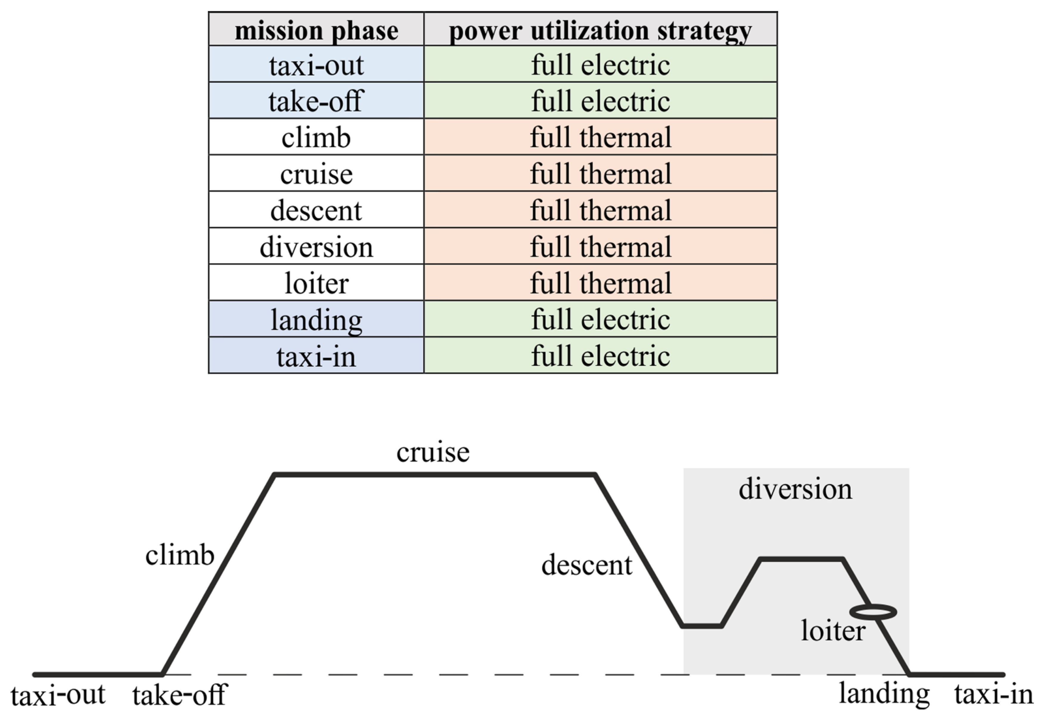
- The hybrid-electric powertrain architecture is assumed to be parallel; the integration of the two power units, at this conceptual stage, is assumed according to the scheme proposed in [44]. Specifically, the electric motor is directly connected to the low-pressure shaft of the engine; this solution avoids the need for a gearbox. Furthermore, the electric motor is located in the cold section of the engine, reducing the risks of overheating [44]. This architecture allows to simultaneously supply power to the fan from both the thermal and electrical sources, so that the two power sources can supply power in different shares during each mission timestep;
- The battery energy density (BED) @pack level is assumed equal to 500 Wh/kg [45];
- The electric motor power density is assumed to be equal to 15 kW/kg [45];
- The electric power cable density per linear meter is assumed equal to 6.5 kg/m [44].
3. Retrofit Strategy towards the Improvement of Local Air Quality
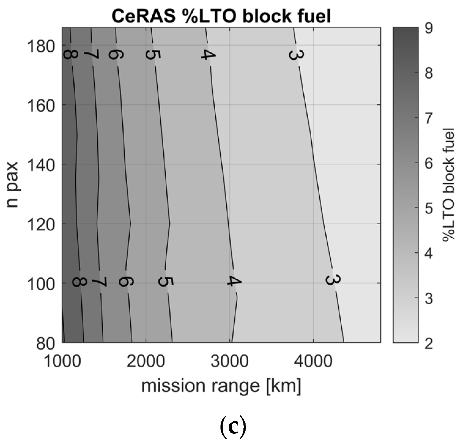
3.1. Local Air Quality
3.2. Retrofit Procedure
3.3. Retrofit Results
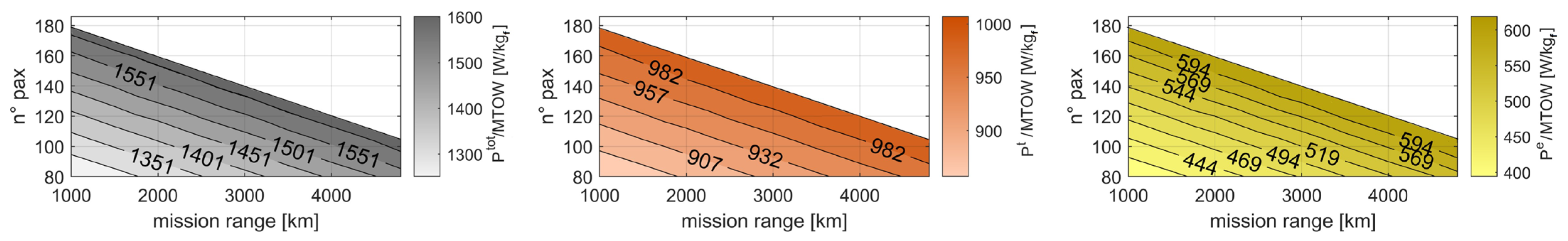
- In the first step, called the design phase, the baseline aircraft is retrofitted for each pair of values of number of passengers and flight distance considered (according to the workflow of Figure 3). For example, an aircraft with a number of passengers equal to 115 and a flight distance equal to 2000 km will have a cabin reconfigured with 115 seats equal and a harmonic range of 2000 km. The hybrid propulsion system is sized to meet the power requirements for this specific design point. For the considered design point, the take-off weight WTO calculated within the retrofitting procedure corresponds to its MTOW; this is always lower than the MTOW of the baseline.
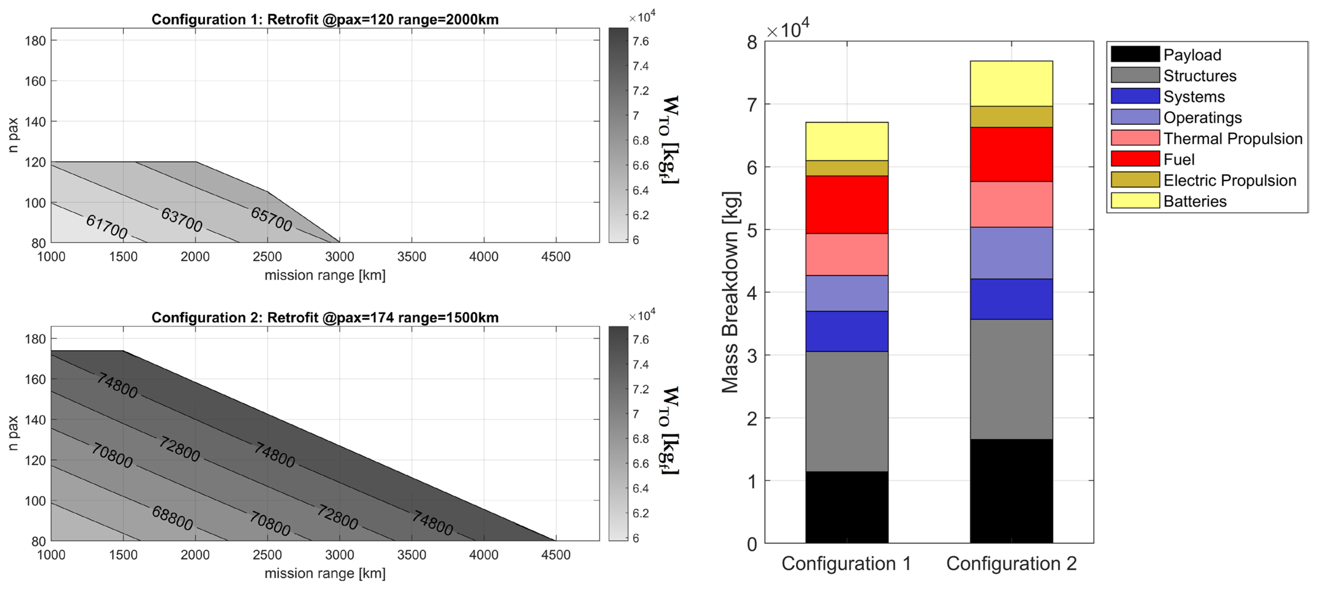
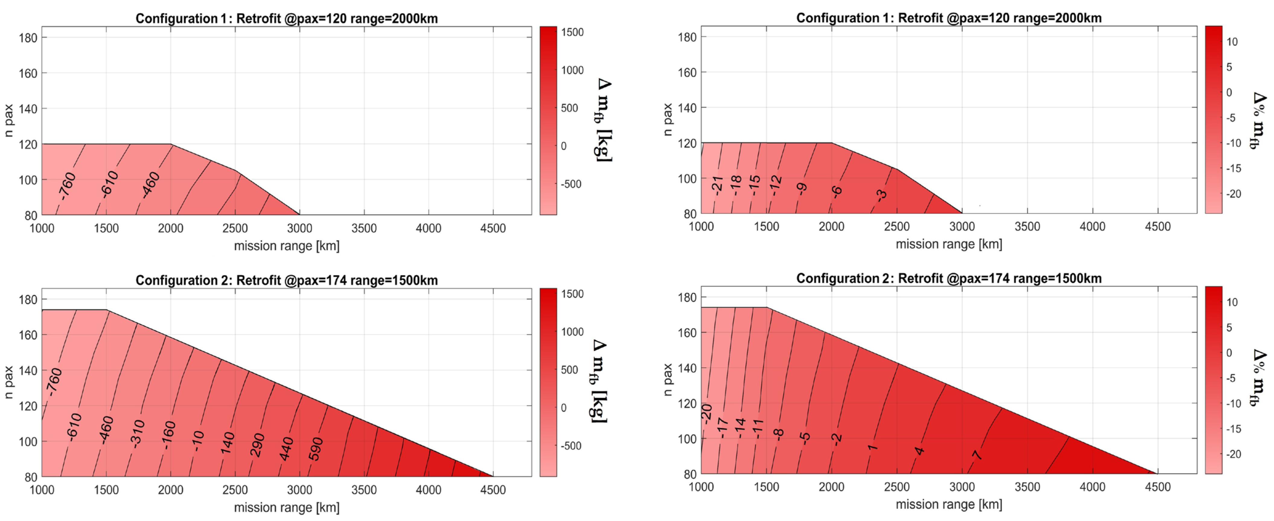
- In a second step, called the analysis phase, representative configurations are selected from those evaluated in the design phase, and the performance within their allowable payload-range envelope is evaluated.
- Operating mass, which mainly depends on the number of passengers;
- Fuel and battery mass required at the design point;
- Take-off weight;
- Mass breakdown of Configurations 1 and 2.
3.4. Performance Comparison with the Baseline Aircraft
4. Re-Design Strategy towards the Reduction in Greenhouse Emissions
4.1. Climate Change
4.2. Re-Design Strategy
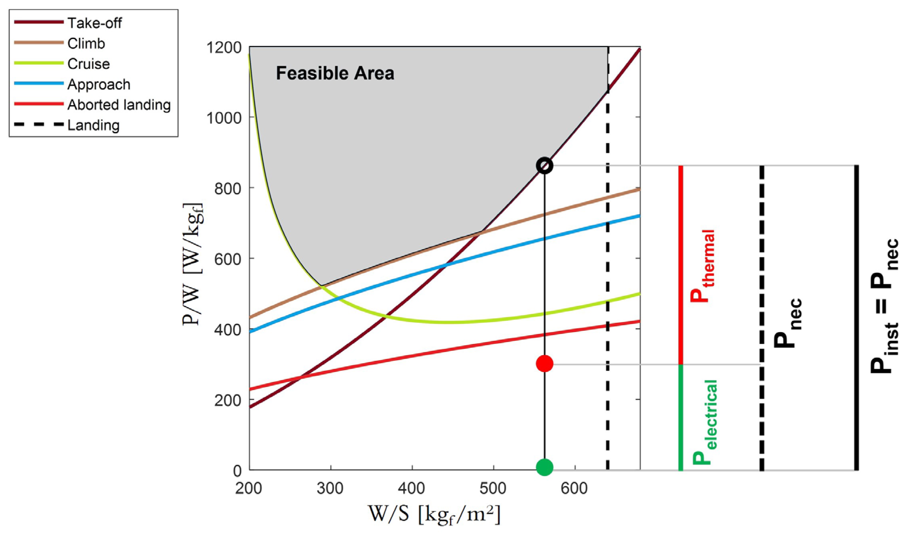
- W/S: aircraft wing loading; W is the design weight; and S is the wing reference area;
- HP: degree of power hybridisation, defined as in Equation (10), where is the electrical installed power, and is the thermal installed power;
- : power fraction supplied by thermal engine in climb;
- : power fraction supplied by thermal engine in cruise;
- : power fraction supplied by thermal engine in descent.
4.3. Re-Design Results
5. Conclusions
Author Contributions
Funding
Data Availability Statement
Conflicts of Interest
List of Symbols and Abbreviations
| Symbol | Description | Unit |
| CD | Aircraft drag coefficient | - |
| CL | Aircraft lift coefficient | - |
| CLmax | Maximum lift coefficient | - |
| Ct | Thrust specific fuel consumption | 1/s |
| D | Aircraft drag | N |
| g | Gravitational acceleration | m/s2 |
| HP | Degree of power hybridization | - |
| ke | One engine inoperative factor | - |
| kV2 | Take-off final speed—stall speed ratio | - |
| kVA | Approach speed—stall speed ratio | - |
| kVR | Rotation speed—stall speed ratio | - |
| kVT | Touch down speed—stall speed ratio | - |
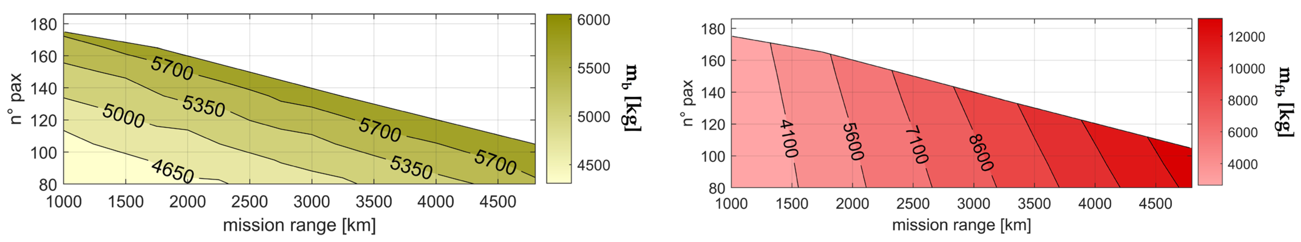
| Battery mass | kg | |
| Block fuel mass | kg | |
| L | Aircraft lift | N |
| lTO | Balanced field length | m |
| P | Power request to fly | W |
| P/W | Specific power | W/N |
| Pb | Power supplied by the battery pack | W |
| Installed electric motor power | W | |
| Power supplied by thermal engine | W | |
| Installed thermal engine power | W | |
| q | Dynamic pressure | Pa |
| RN | Vertical ground reaction force | N |
| RT | Horizontal ground reaction force | N |
| S | Wing reference area | m2 |
| SLO | Distance covered during lift-off | m |
| SR | Distance covered during rotation | m |
| T | Engine thrust | N |
| V | Aircraft true air speed | m/s |
| W | Aircraft weight | N |
| WTO | Aircraft take-off weight | N |
| W/S | Wing loading | N/m2 |
| γ | Trajectory slope | rad |
| ηec | Electric chain efficiency | - |
| ηp | Propulsive efficiency | - |
| ηtc | Thermal chain efficiency | - |
| μTO | Friction coefficient during ground roll | - |
| ρ | Air density | kg/m3 |
| φ | Take-off distance safety factor | - |
| ϕe | Power fraction supplied by the electric motor | - |
| ϕt | Power fraction supplied by the thermal engine | - |
| Abbreviations | ||
| AVL | Athena Vortex Lattice | |
| BED | Gravimetric battery energy density | |
| CeRAS | Central reference aircraft data system | |
| LTO | Landing and take-off cycle | |
| MTOW | Maximum take-off weight | |
| PM | Particulate matter | |
| RF | Radiative forcing | |
| SMR | Short-medium range | |
| THEA-CODE | Tool for hybrid-electric aircraft conceptual design | |
| TLAR | Top level aircraft requirements | |
| VLM | Vortex Lattice Method | |
| VOC | Volatile organic compounds | |
Appendix A
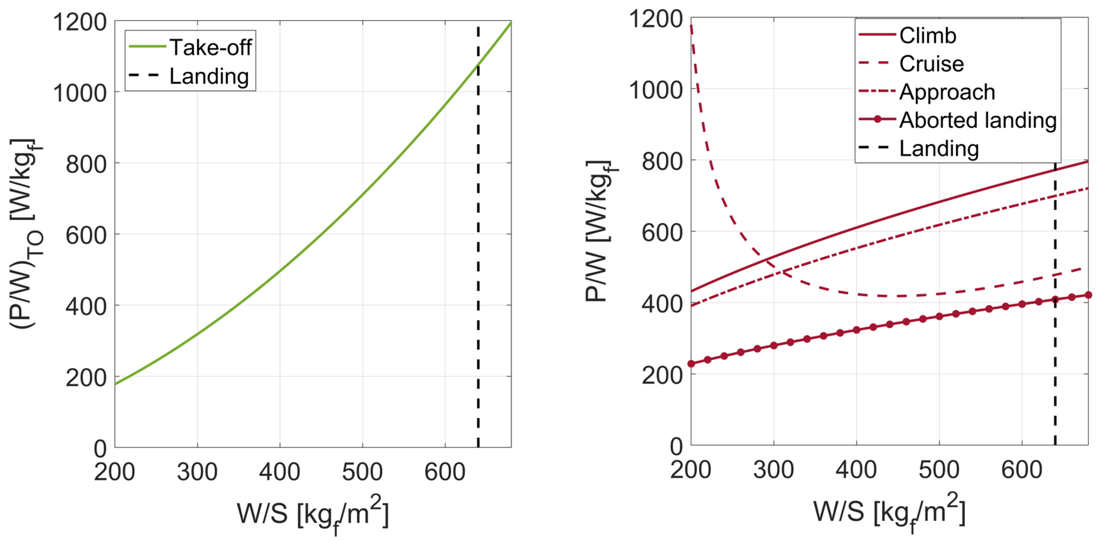
- Take-off constraint—Equation (1)
- Climb and obstacle limitations—Equation (2)
- Cruise—Equation (3)
- Aborted landing—Equation (4)
References
- Brooker, P. Civil aircraft design priorities: Air quality? climate change? noise? Aeronaut. J. 2006, 110, 517–532. [Google Scholar] [CrossRef]
- Stettler, M.E.J.; Eastham, S.; Barrett, S.R.H. Air quality and public health impacts of UK airports. Part I: Emissions. Atmos. Environ. 2011, 45, 5415–5424. [Google Scholar] [CrossRef]
- Parker, R. From blue skies to green skies: Engine technology to reduce the climate-change impacts of aviation. Technol. Anal. Strat. Manag. 2009, 21, 61–78. [Google Scholar] [CrossRef]
- ICAO. Local Air Quality Technology Standards. 2017. Available online: https://www.icao.int/environmental-protection/Pages/LAQ_TechnologyStandards.aspx (accessed on 18 April 2023).
- Brelje, B.J.; Martins, J.R. Electric, hybrid, and turboelectric fixed-wing aircraft: A review of concepts, models, and design approaches. Prog. Aerosp. Sci. 2018, 104, 1–19. [Google Scholar] [CrossRef]
- Abu Salem, K.; Palaia, G.; Quarta, A.A. Review of hybrid-electric aircraft technologies and designs: Critical analysis and novel solutions. Prog. Aerosp. Sci. 2023; under review. [Google Scholar]
- Zhao, L.; Lakraychi, A.E.; Chen, Z.; Liang, Y.; Yao, Y. Roadmap of Solid-State Lithium-Organic Batteries toward 500 Wh kg−1. ACS Energy Lett. 2021, 6, 3287–3306. [Google Scholar] [CrossRef]
- Riboldi, C.; Gualdoni, F. An integrated approach to the preliminary weight sizing of small electric aircraft. Aerosp. Sci. Technol. 2016, 58, 134–149. [Google Scholar] [CrossRef]
- Finger, D.F.; Bil, C.; Braun, C. Initial Sizing Methodology for Hybrid-Electric General Aviation Aircraft. J. Aircr. 2020, 57, 245–255. [Google Scholar] [CrossRef]
- Isikveren, A.T.; Fefermann, Y.; Maury, C.; Level, C.; Zarati, K.; Salanne, J.-P.; Pornet, C.; Thoraval, B. Pre-design of a commuter transport utilising Voltaic-Joule/Brayton motive power systems. Aeronaut. J. 2017, 122, 205–237. [Google Scholar] [CrossRef]
- Orefice, F.; Nicolosi, F.; Della Vecchia, P.; Ciliberti, D. Aircraft Conceptual Design of Commuter Aircraft including Distributed Electric Propulsion. In Proceedings of the AIAA Aviation 2020 Forum, Virtual, 15–19 June 2020. [Google Scholar] [CrossRef]
- Rolando, A.; Salucci, F.; Trainelli, L.; Riboldi, C.E.; Khan, Y.M. On the Design of an Electric-Powered Micro-Feeder Aircraft. In Proceedings of the 1st Aerospace Europe Conference, Bordeaux, France, 25–28 February 2020. [Google Scholar]
- Palaia, G.; Abu Salem, K.; Cipolla, V.; Binante, V.; Zanetti, D. A Conceptual Design Methodology for e-VTOL Aircraft for Urban Air Mobility. Appl. Sci. 2021, 11, 10815. [Google Scholar] [CrossRef]
- Donateo, T.; Ficarella, A. A Methodology for the Comparative Analysis of Hybrid Electric and All-Electric Power Systems for Urban Air Mobility. Energies 2022, 15, 638. [Google Scholar] [CrossRef]
- Voskuijl, M.; van Bogaert, J.; Rao, A.G. Analysis and design of hybrid electric regional turboprop aircraft. CEAS Aeronaut. J. 2017, 9, 15–25. [Google Scholar] [CrossRef]
- Palaia, G.; Abu Salem, K. Mission Performance Analysis of Hybrid-Electric Regional Aircraft. Aerospace 2023, 10, 246. [Google Scholar] [CrossRef]
- Hoelzen, J.; Liu, Y.; Bensmann, B.; Winnefeld, C.; Elham, A.; Friedrichs, J.; Hanke-Rauschenbach, R. Conceptual Design of Operation Strategies for Hybrid Electric Aircraft. Energies 2018, 11, 217. [Google Scholar] [CrossRef]
- De Vries, R.; Brown, M.; Vos, R. Preliminary Sizing Method for Hybrid-Electric Distributed-Propulsion Aircraft. J. Aircr. 2019, 56, 2172–2188. [Google Scholar] [CrossRef]
- Palaia, G. Design and Performance Assessment Methodologies for Box-Wing Hybrid-Electric Aircraft from Urban to Regional Transport Applications. Ph.D. Thesis, University of Pisa, Pisa, Italy, 2022. Available online: https://etd.adm.unipi.it/t/etd-11092022-150110/ (accessed on 18 April 2023).
- Airbus. Global Market Forecast 2021–2040. 2022. Available online: https://www.airbus.com/en/products-services/commercial-aircraft/market/global-market-forecast (accessed on 18 April 2023).
- Graver, B.; Zhang, K.; Rutherford, D. CO2 emissions from commercial aviation. In The International Council on Clean Transportation; ICCT: Washington, DC, USA, 2018; Available online: https://theicct.org/publications/co2-emissions-commercial-aviation-2018 (accessed on 18 April 2023).
- Pornet, C.; Isikveren, A. Conceptual design of hybrid-electric transport aircraft. Prog. Aerosp. Sci. 2015, 79, 114–135. [Google Scholar] [CrossRef]
- Gnadt, A.R.; Speth, R.L.; Sabnis, J.S.; Barrett, S.R. Technical and environmental assessment of all-electric 180-passenger commercial aircraft. Prog. Aerosp. Sci. 2018, 105, 1–30. [Google Scholar] [CrossRef]
- Sgueglia, A.; Schmollgruber, P.; Bartoli, N.; Benard, E.; Morlier, J.; Jasa, J.; Martins, J.R.R.A.; Hwang, J.T.; Gray, J.S. Multidisciplinary Design Optimization Framework with Coupled Derivative Computation for Hybrid Aircraft. J. Aircr. 2020, 57, 715–729. [Google Scholar] [CrossRef]
- Risse, K.; Schäfer, K.; Schültke, F.; Stumpf, E. Central Reference Aircraft data System (CeRAS) for research community. CEAS Aeronaut. J. 2015, 7, 121–133. [Google Scholar] [CrossRef]
- CeRAS. Central Reference Aircraft System. Website. 2016. Available online: https://ceras.ilr.rwth-aachen.de/ (accessed on 18 April 2023).
- Abu Salem, K.; Cipolla, V.; Palaia, G.; Binante, V.; Zanetti, D. A Physics-Based Multidisciplinary Approach for the Preliminary Design and Performance Analysis of a Medium Range Aircraft with Box-Wing Architecture. Aerospace 2021, 8, 292. [Google Scholar] [CrossRef]
- Palaia, G.; Zanetti, D.; Abu Salem, K.; Cipolla, V.; Binante, V. THEA-CODE: A design tool for the conceptual design of hybrid-electric aircraft with conventional or unconventional airframe configurations. Mech. Ind. 2021, 22, 19. [Google Scholar] [CrossRef]
- Drela, M.; Youngren, H. AVL 3.36 User Primer, Online Software Manual. 2017. Available online: https://perma.cc/R35R-W29F (accessed on 18 April 2023).
- Raymer, P. Aircraft Design: A Conceptual Approach; AIAA Education Series; American Institute of Aeronautics and Astronautics Inc.: Reston, VA, USA, 1992; ISBN 0-930403-51-7. [Google Scholar]
- Mason, W. Analytic models for technology integration in aircraft design. In Proceedings of the Aircraft Design, Systems and Operations Conference, Dayton, OH, USA, 17–19 September 1990. [Google Scholar] [CrossRef]
- Gu, X.; Ciampa, P.D.; Nagel, B. An automated CFD analysis workflow in overall aircraft design applications. CEAS Aeronaut. J. 2017, 9, 3–13. [Google Scholar] [CrossRef]
- Wang, Z.J. High-order computational fluid dynamics tools for aircraft design. Philos. Trans. R. Soc. A Math. Phys. Eng. Sci. 2014, 372, 20130318. [Google Scholar] [CrossRef] [PubMed]
- Da Ronch, A.; Ghoreyshi, M.; Badcock, K. On the generation of flight dynamics aerodynamic tables by computational fluid dynamics. Prog. Aerosp. Sci. 2011, 47, 597–620. [Google Scholar] [CrossRef]
- Carini, M.; Meheut, M.; Kanellopoulos, S.; Cipolla, V.; Abu Salem, K. Aerodynamic analysis and optimization of a boxwing architecture for commercial airplanes. In Proceedings of the AIAA Scitech 2020 Forum, Orlando, FL, USA, 6–10 January 2020. [Google Scholar] [CrossRef]
- Fioriti, M. Adaptable conceptual aircraft design model. Adv. Aircr. Spacecr. Sci. 2014, 1, 43–67. [Google Scholar] [CrossRef]
- Sforza, P.M. Commercial Airplane Design Principles; Elsevier: Amsterdam, The Netherlands, 2014. [Google Scholar]
- FAR 25; Airworthiness Standards: Transport Category Airplanes. FAA: Washington, DC, USA, 1980.
- Mair, W.A.; Birdsall, D.L. Aircraft Performance; Cambridge University Press: Cambridge, UK, 1992. [Google Scholar] [CrossRef]
- Airbus. Getting to Grips with Aircraft Performance, Airbus SAS. 2002. Available online: https://perma.cc/FQ9P-FET4 (accessed on 18 April 2023).
- Abu Salem, K. Development of Design Tools and Methods for Box-Wing Airplanes and Application of the PrandtlPlane Concept to a Short-Medium Range Aircraft. Ph.D. Thesis, University of Pisa, Pisa, Italy, 2021. Available online: https://etd.adm.unipi.it/theses/available/etd-05312021-171241/ (accessed on 18 April 2023).
- Wells, D.; Horvath, B.; McCullers, L. The Flight Optimization System Weights Estimation Method. NASA Technical Memorandum; No. 2017-219627. 2017. Available online: https://ntrs.nasa.gov/citations/20170005851 (accessed on 18 April 2023).
- Abu Salem, K.; Giuseppe, P.; Vittorio, C.; Vincenzo, B.; Davide, Z.; Mario, C. Tools and methodologies for box-wing aircraft conceptual aerodynamic design and aeromechanic analysis. Mech. Ind. 2021, 22, 39. [Google Scholar] [CrossRef]
- Seitz, A.; Nickl, M.; Stroh, A.; Vratny, P.C. Conceptual study of a mechanically integrated parallel hybrid electric turbofan. Proc. Inst. Mech. Eng. Part G J. Aerosp. Eng. 2018, 232, 2688–2712. [Google Scholar] [CrossRef]
- Dever, T.P.; Duffy, K.P.; Provenza, A.J.; Loyselle, P.L.; Choi, B.B.; Morrison, C.R.; Lowe, A.M. Assessment of Technologies for Noncryogenic Hybrid Electric Propulsion; Report NASA TP-2015-216588. 2015. Available online: https://ntrs.nasa.gov/citations/20150000747 (accessed on 18 April 2023).
- ICAO. Global Air Transport Outlook to 2030 and Trends to 2040; ICAO: Rio de Janeiro, Brazil, 2013. [Google Scholar]
- Eurocontrol. European Aviation in 2040, Challenges of Growth, Annex 1, Flight Forecast to 2040. 2018. Available online: https://perma.cc/YW6Y-JU7J (accessed on 18 April 2023).
- Eurocontrol. European Aviation in 2040, Challenges of Growth. 2018. Available online: https://perma.cc/2A2J-B7PW (accessed on 18 April 2023).
- Yang, X.; Cheng, S.; Lang, J.; Xu, R.; Lv, Z. Characterization of aircraft emissions and air quality impacts of an international airport. J. Environ. Sci. 2018, 72, 198–207. [Google Scholar] [CrossRef]
- Rissman, J.; Arunachalam, S.; Woody, M.; West, J.J.; BenDor, T.; Binkowski, F.S. A plume-in-grid approach to characterize air quality impacts of aircraft emissions at the Hartsfield–Jackson Atlanta International Airport. Atmos. Chem. Phys. 2013, 13, 9285–9302. [Google Scholar] [CrossRef]
- Hudda, N.; Durant, L.W.; Fruin, S.A.; Durant, J.L. Impacts of Aviation Emissions on Near-Airport Residential Air Quality. Environ. Sci. Technol. 2020, 54, 8580–8588. [Google Scholar] [CrossRef]
- Simonetti, I.; Maltagliati, S.; Manfrida, G. Air quality impact of a middle size airport within an urban context through EDMS simulation. Transp. Res. Part D Transp. Environ. 2015, 40, 144–154. [Google Scholar] [CrossRef]
- Zhu, Y.; Fanning, E.; Yu, R.C.; Zhang, Q.; Froines, J.R. Aircraft emissions and local air quality impacts from takeoff activities at a large International Airport. Atmos. Environ. 2011, 45, 6526–6533. [Google Scholar] [CrossRef]
- Winther, M.; Kousgaard, U.; Ellermann, T.; Massling, A.; Nøjgaard, J.K.; Ketzel, M. Emissions of NO x, particle mass and particle numbers from aircraft main engines, APU’s and handling equipment at Copenhagen Airport. Atmos. Environ. 2015, 100, 218–229. [Google Scholar] [CrossRef]
- Yim, S.H.; Stettler, M.E.; Barrett, S.R. Air quality and public health impacts of UK airports. Part II: Impacts and policy assessment. Atmos. Environ. 2013, 67, 184–192. [Google Scholar] [CrossRef]
- Aircraft air pollutant emissions in Greek airports. Glob. NEST Int. J. 2013, 11, 528–534. [CrossRef]
- Vratny, P.C.; Kling, U. Impact of Electric Taxiing on Hybrid-Electric Aircraft Sizing; Deutsche Gesellschaft für Luft-und Raumfahrt-Lilienthal-Oberth eV: Bonn, Germany, 2019. [Google Scholar]
- Pornet, C.; Gologan, C.; Vratny, P.C.; Seitz, A.; Schmitz, O.; Isikveren, A.T.; Hornung, M. Methodology for Sizing and Performance Assessment of Hybrid Energy Aircraft. J. Aircr. 2015, 52, 341–352. [Google Scholar] [CrossRef]
- Ang, A.W.X.; Rao, A.G.; Kanakis, T.; Lammen, W. Performance analysis of an electrically assisted propulsion system for a short-range civil aircraft. Proc. Inst. Mech. Eng. Part G J. Aerosp. Eng. 2018, 233, 1490–1502. [Google Scholar] [CrossRef]
- Gesell, H.; Wolters, F.; Plohr, M. System analysis of turbo-electric and hybrid-electric propulsion systems on a regional aircraft. Aeronaut. J. 2019, 123, 1602–1617. [Google Scholar] [CrossRef]
- Shine, K.P.; Derwent, R.G.; Wuebbles, D.J.; Morcrette, J.J. Radiative forcing of climate. In Climate Change: The IPCC Scientific Assessment; 1990; pp. 41–68. Available online: https://pure.mpg.de/rest/items/item_3475154/component/file_3475155/content (accessed on 18 April 2023).
- Lee, D.S.; Fahey, D.W.; Forster, P.M.; Newton, P.J.; Wit, R.C.N.; Lim, L.L.; Owen, B.; Sausen, R. Aviation and global climate change in the 21st century. Atmos. Environ. 2009, 43, 3520–3537. [Google Scholar] [CrossRef]
- Lee, D.; Pitari, G.; Grewe, V.; Gierens, K.; Penner, J.; Petzold, A.; Prather, M.; Schumann, U.; Bais, A.; Berntsen, T. Transport impacts on atmosphere and climate: Aviation. Atmos. Environ. 2010, 44, 4678–4734. [Google Scholar] [CrossRef]
- Ribeiro, S.K.; Kobayashi, S.; Beuthe, M.; Gasca, J.; Greene, D.; Lee, D.S.; Muromachi, Y.; Newton, P.J.; Plotkin, S.; Sperling, D.; et al. Transportation and its Infrastructure. UC Davis: Institute of Transportation Studies. 2007. Available online: https://escholarship.org/uc/item/98m5t1rv (accessed on 18 April 2023).
- McNutt, M. Climate Change Impacts. Science 2013, 341, 435. [Google Scholar] [CrossRef] [PubMed]
- Calzadilla, A.; Rehdanz, K.; Betts, R.; Falloon, P.; Wiltshire, A.; Tol, R. Climate change impacts on global agriculture. Clim. Change 2013, 120, 357–374. [Google Scholar] [CrossRef]
- Wheeler, T.; Von Braun, J. Climate Change Impacts on Global Food Security. Science 2013, 341, 508–511. [Google Scholar] [CrossRef] [PubMed]
- Kaczan, D.J.; Orgill-Meyer, J. The impact of climate change on migration: A synthesis of recent empirical insights. Clim. Change 2019, 158, 281–300. [Google Scholar] [CrossRef]
- Haines, A.; Patz, J.A. Health Effects of Climate Change. JAMA 2004, 291, 99. [Google Scholar] [CrossRef]
- Tasca, A.L.; Cipolla, V.; Abu Salem, K.; Puccini, M. Innovative Box-Wing Aircraft: Emissions and Climate Change. Sustainability 2021, 13, 3282. [Google Scholar] [CrossRef]
- Fletcher, R. Practical Methods of Optimization; John Wiley & Sons: Hoboken, NJ, USA, 2013; ISBN 978-1-118-72318-0. [Google Scholar]


| Local Air Quality | Climate Change | |
|---|---|---|
| Mission phase | LTO cycle | Entire mission |
| Impactful emissions | NOx, SOx, VOC, PM | CO2, NOx, water vapour, soot particles |
| Space-scale | Airport regions | Global effects |
| Effects | Direct damage to health | Large-scale effects, catastrophic implications |
| Proposed solution | Hybrid-electric propulsion retrofit for LTO emission suppression | Hybrid-electric aircraft redesign for block fuel minimisation |
Disclaimer/Publisher’s Note: The statements, opinions and data contained in all publications are solely those of the individual author(s) and contributor(s) and not of MDPI and/or the editor(s). MDPI and/or the editor(s) disclaim responsibility for any injury to people or property resulting from any ideas, methods, instructions or products referred to in the content. |
© 2023 by the authors. Licensee MDPI, Basel, Switzerland. This article is an open access article distributed under the terms and conditions of the Creative Commons Attribution (CC BY) license (https://creativecommons.org/licenses/by/4.0/).
Share and Cite
Abu Salem, K.; Palaia, G.; Quarta, A.A.; Chiarelli, M.R. Medium-Range Aircraft Conceptual Design from a Local Air Quality and Climate Change Viewpoint. Energies 2023, 16, 4013. https://doi.org/10.3390/en16104013
Abu Salem K, Palaia G, Quarta AA, Chiarelli MR. Medium-Range Aircraft Conceptual Design from a Local Air Quality and Climate Change Viewpoint. Energies. 2023; 16(10):4013. https://doi.org/10.3390/en16104013
Chicago/Turabian StyleAbu Salem, Karim, Giuseppe Palaia, Alessandro A. Quarta, and Mario R. Chiarelli. 2023. "Medium-Range Aircraft Conceptual Design from a Local Air Quality and Climate Change Viewpoint" Energies 16, no. 10: 4013. https://doi.org/10.3390/en16104013