Review

Towards the Development of Miniature Scale Liquid Fuel Combustors for Power Generation Application—A Review

by
Vinay Sankar
1,
Sreejith Sudarsanan
2,
Sudipto Mukhopadhyay
1,
Prabhu Selvaraj
2,
Aravind Balakrishnan
3 and
Ratna Kishore Velamati
2,*
1
Department of Mechanical Engineering, Indian Institute of Technology Jodhpur, Rajasthan 342037, India
2
Department of Mechanical Engineering, Amrita School of Engineering Coimbatore, Amrita Vishwa Vidyapeetham, Tamil-Nadu 641112, India
3
Department of Aerospace Engineering, Indian Institute of Technology Bombay, Powai, Mumbai 400076, India
*
Author to whom correspondence should be addressed.
Energies 2023, 16(10), 4035; https://doi.org/10.3390/en16104035
Submission received: 28 March 2023 / Revised: 2 May 2023 / Accepted: 4 May 2023 / Published: 11 May 2023

Abstract

:
As the demand for powerful, light energy sources continues to grow, traditional electrochemical batteries are no longer sufficient and combustion-based power generation devices have become an attractive alternative due to their high energy density, compact size, fast recharging time and long service life. While most research on miniature-scale combustors has focused on gaseous fuels, the use of commonly available liquid fuels has the potential to be highly portable and economical. However, the complexity of droplet atomization, evaporation, mixing and burning in a limited volume and short residence time has presented significant challenges for researchers. This review focuses on various methodologies proposed by researchers (like flow burring injector, fuel film injection, injecting into porous media, electrospray and some self-aspirating designs) to overcome these challenges, the combustion behaviour and different instabilities associated with liquid fuels at small scales. The current review intends to present a clear direction to channel the efforts made by researchers to overcome the difficulties associated with liquid fuel combustion at small scales for power generation applications. Additionally, this review aims to give an overview of power systems at the micro and meso scales that operate using liquid fuels. The methodologies introduced like electrospray requires external power, which again makes the system complex. Towards the development of standalone type power generators, the self-aspirating design which makes use of hydrostatic pressure, fuel film injection or taking advantage of exhaust gas enthalpy to preheat and evaporate the liquid fuel are the promising methodologies.

1. Background

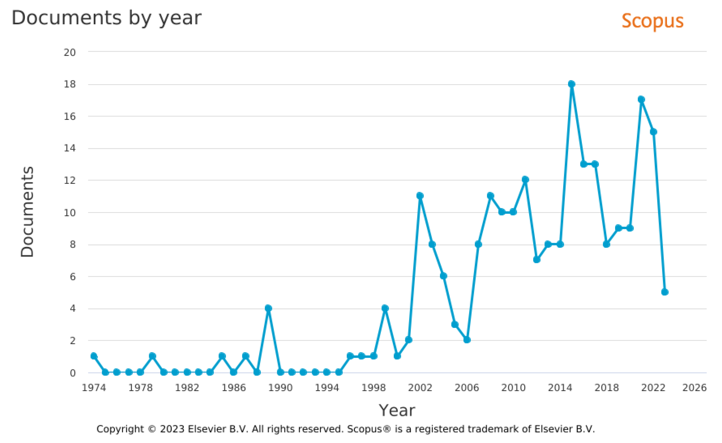
The swift advancement of micro fabrication technologies has already started driving engineering systems towards miniaturization, which in turn created a pressing demand for small, adaptable power sources [1]. Currently these small scale devices do rely on traditional electro-chemical batteries [2,3]. Battery technology has advanced greatly in recent times, which subsequently lead to the development of new anodes, cathodes and the capability to recharge them. Even then the battery technology has fallen behind owing to its low energy density, environmental issues associated with battery disposal and cumbersome weight [4,5]. And hence the military, as well as civilian sectors, have shown a keen interest in alternative power generation systems [6,7]. The absence of a tiny but powerful energy source has currently been preventing further progress in the advancement of wireless micro-systems, which are fundamental components considering the creation of next-generation sensing systems. The requirement of small-scale power devices in military and domestic applications necessitates the need for combustion-based power generators. The data depicted in Figure 1 reveals a significant surge in the annual publications for “micro combustor” or “meso combustor” or “miniature combustor” and “power generation” as the keyword. This increase is a clear sign of the growing interest towards this technology among the scientific community.

1.1. Need for Liquid Fuel Power Systems

It is vividly understood from Figure 2 that the miniature scale combustors working on liquid fuels make the entire system, a smaller as well as lighter one. Liquid fuels tend to have higher volumetric and gravimetric energy densities when compared to gaseous fuels, which means that they are able to store more energy per unit volume or mass. This can be considered as an important upper hand for liquid fuels in the perspective of portable power generators, where space and weight are the prime concerns. Figure 3 shows a noticeable increase in the number of publications over the past decades for “liquid fuel” or “electrospray” or “liquid fuel film” or “spray” and “micro combustor” as the keyword.

1.2. Application and Different Power Ranges Required

The high energy density of hydrocarbon fuels provides a great opportunity for combustion-based micro-power generation systems to be developed to support the increasing demand for portable devices such as personal networks, handheld or hand-launched robots, artificial organs, exoskeletal systems, micro unmanned aerial vehicles, micro-satellite thrusters, microchemical reactors and sensors etc, as all of them require compact, efficient, and human-compatible power sources. The power requirements for different applications are depicted in Figure 4. The micro power systems, as depicted, are utilized in various capacities, including both national security and personal mobility. From Figure 4, it can be seen that the power consumption of these gadgets falls within a range of 10 watts to 1000 watts.

1.3. Different Scale of Combustors

Defining “micro-scale combustion” has been often challenging due to the arbitrary choices of their reference length scales and even it can sometimes lead to confusion with “mesoscale combustion” [12]. The definition of micro-scale combustion has often incorporated three length scales, as observed in previous studies. The first one is based on the physical dimension of the combustor, combustion is classified as micro-combustion if the physical length scale of the combustor is less than 1 mm, and mesoscale combustion if it falls between 1 mm and 1 cm. The second definition is based on the quenching diameter of the flame. According to the quenching diameter as length scale, combustion is said to be at a micro-scale if the combustor size is smaller than the quenching diameter. It is challenging to precisely define the boundary between micro and mesoscale combustion because the quenching diameter is influenced by a variety of factors, such as mixture composition, wall properties etc. Another approach to defining micro and mesoscale combustion is by comparing the size of the device to conventional large-scale devices used for similar purposes. Table 1 summarises the definition of micro and meso scale combustion using different length scales.

1.4. Central Theme of Preceding and Current Review

Several researchers have reported developments in the field of small-scale combustion in past decades. Fernandez-Pello [13] examined the challenges and strategies involved in developing micro-scale power generation systems. In 2005, Dunn-Rankin came up with several personal power systems [10]. Ju and Maruta [12] in 2011 presented a detailed summary of the progress made in micro-scale combustion, covering both the technological advancements and fundamental research related to micro-power generators utilizing thermo-chemical processes. Walther et al. [14] highlighted technological issues related to micro-scale combustion and thermo-chemical devices for power generation, as well as the advances, and opportunities in this field and also provided a brief description regarding various fabrication technologies being employed. Kaisare et al. [11] investigated the multiple aspects of micro-combustion, comprising the fabrication techniques, design considerations and operational procedures. He also provided with a comprehensive review of different types of micro-burners, including homogeneous, catalytic, homogeneous-heterogeneous, and heat-recirculating burners. Chen et al. [15] presented the results of a thorough examination of different approaches aimed at improving combustion stability and efficiency on a micro-scale system. It covered a variety of micro-thermophotovoltaic power generators and discussed the application of MEMS-based solid propellant micro-propulsion systems. Shirsat et al. [16] made a comprehensive review on heat re-circulating burners with a focus on their thermal performance, extinction criteria/extinction regimes and flame dynamics. Nakamura et al. [17] presented a brief review on small-scale combustion in which they highlighted the effectiveness of heat re-circulation, which is considered a distinctive and advantageous characteristic of small-scale combustion systems. Fan et al. [18] conducted an in-depth study of the recent advancements in flame stabilization technologies as well as underlying mechanisms of various flame anchoring strategies and provided guidelines for developing micro-combustors with excellent flame stabilization capabilities. Aravind et al. [3] performed a comprehensive study of combustion-based power generators, an overall comparison of micro combustion-based thermoelectric generator (TEG) and thermophotovoltaic (TPV) systems.
All the reviews reported have concentrated primarily on gaseous fuel-based micro-combustors. Altogether the aim of this paper is to present a comprehensive review of the literature related to the potential use of liquid fuels in small-scale combustors. In this paper, the recent advancements in micro/mesoscale power system technology utilizing liquid fuel are reviewed. The paper has been broadly classified into five sections. The first section discusses the challenges faced during the combustion of liquid fuels at small scales. Secondly, the fundamental understanding of liquid fuel combustion at small scales under different modes like premixed, non-premixed and partially premixed are discussed. Thirdly, different flame instabilities associated with liquid fuel combustion at a small scale are reviewed. After that, various micro/mesoscale power generators are described. Finally, the outlook for liquid fuel micro/mesoscale combustion research is presented.

2. Mixture Preparation

In order to ensure the successful design of portable power generators, the utilization of liquid fuel has been necessary. Despite several advantages of utilisation of liquid fuels, several problems such as fuel atomization, fuel vaporization and mixing of the fuel-air mixture within the available short residence time have to be addressed before combustion. Following are the methods, which have been introduced by researchers to tackle the above mentioned issues.

2.1. Injectors

Most atomizers do conventionally rely on high flow rates and injection pressures, which make them unsuitable for atomizing ultra-low flow rates that are required for micro-combustion applications [19]. To ensure the efficient operation of liquid-fueled combustion systems, it has been crucial to achieve effective vaporization and thorough premixing of the fuel with air [20].
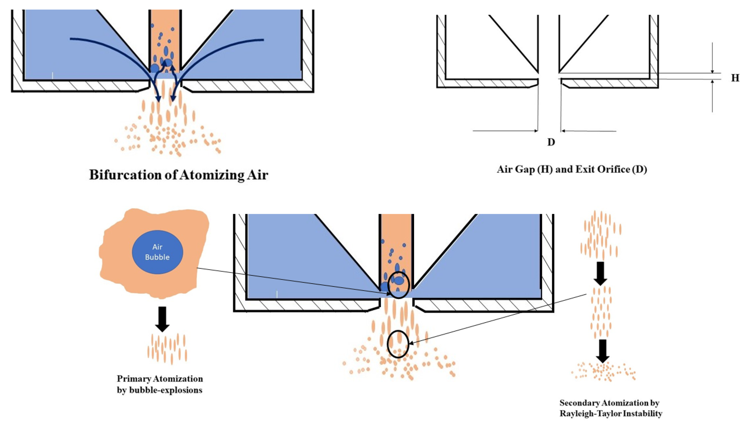
A new twin-fluid injector working on a flow-blurring atomization technique was designed by Ganan-Calvo, which can be used to tackle these issues [21]. The principle behind flow burring injection involved inducing a two-phase flow near the exit of the injector through aerodynamic means, as illustrated in Figure 5.
The flow-blurring injector was operated in such a way that atomizing air and liquid were introduced in a co-flowing manner, then the atomizing air was redirected to circulate back into the liquid tube through a narrow clearance (H) between the tube and orifice plate. This re-circulation mechanism generated a spray with high uniformity and fine droplet size. The optimal spray quality was achieved when the H-to-D ratio was 0.25. An analysis of the literature suggested that liquid fuel flow rates in the order of 10 1 g/s or less are commonly required for small-scale combustion systems [23,24,25]. Table 2 provides a condensed overview of the flow rates for both air and liquid that have been documented in previous works.
The flow-blurring injector was utilized in the meso-scale combustion system in order to create fine fuel droplets from both kerosene and vegetable oil [20,26].
Table 2. Summary of air and liquid flow rates reported in the literature.
Previous WorksLiquidLiquid Flow Rate (mg/s)Air Flow Rate (g/s)
Simmons et al. [27]Water80–8300.2–0.8
Jiang et al. [28]Water2000.4
Azevedo et al. [29]Water120–4700.037–0.238
Azevedo et al. [30]soy methyl ester biodiesel110–5600.026–0.107
Azevedo et al. [31]Ethanol80–4200.082–0.24
Azad et al. [19]Water, Glycerine-water, Ethanol2.22–50.30.01–0.1

2.2. Fuel Film

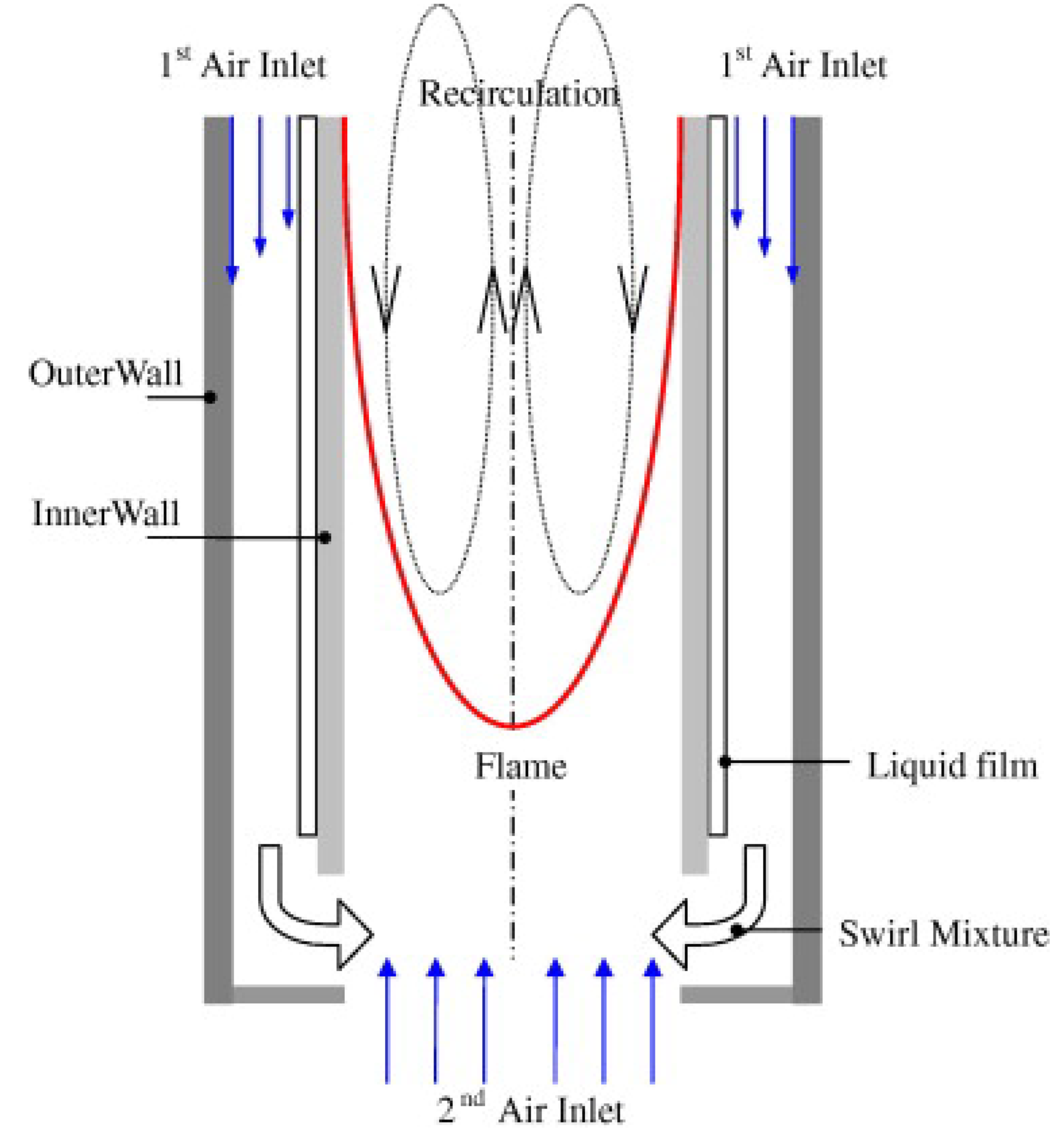
To ensure atomization at extremely low flow rates, fuel film strategies were introduced by researchers. Here, the liquid fuel was injected as a thin film through the inner surface of the combustion chamber, which utilized the heat loss from the combustor walls to enhance the rate at which the fuel evaporates [24,32]. This concept makes use of the vast surface area available by introducing a swirling air flow so that a liquid fuel film is created on the inner walls of the combustion chamber. Figure 6 demonstrates the concept of fuel film injection.
Here, the fuel film serves as a buffer between the hot combustion gases and combustor walls. Subsequently, the heat from the hot combustion gas products was utilized to vaporize the fuel film instead of conducting it to the walls and preventing quenching [33].
In light of the limitations observed in the original liquid film combustor concept, certain modifications were introduced [34]. The first one is a fuel film double chamber combustor shown in Figure 7.
The combustor consisted of two concentric cylindrical walls with a gap of a few millimetres between them. The inner one acted as a combustion chamber, while the outer wall created an annular space where the fuel was injected. The fuel film formed in the outer chamber cools the inner chamber. Fuel flowed into one end of the outer chamber and progressed towards the other end, where it entered into the inner chamber (combustion chamber). Air was also injected into the annulus, where it get premixed with the vaporized fuel. The mechanism of evaporation and combustion in this fuel film double chamber combustor is depicted in Figure 8.
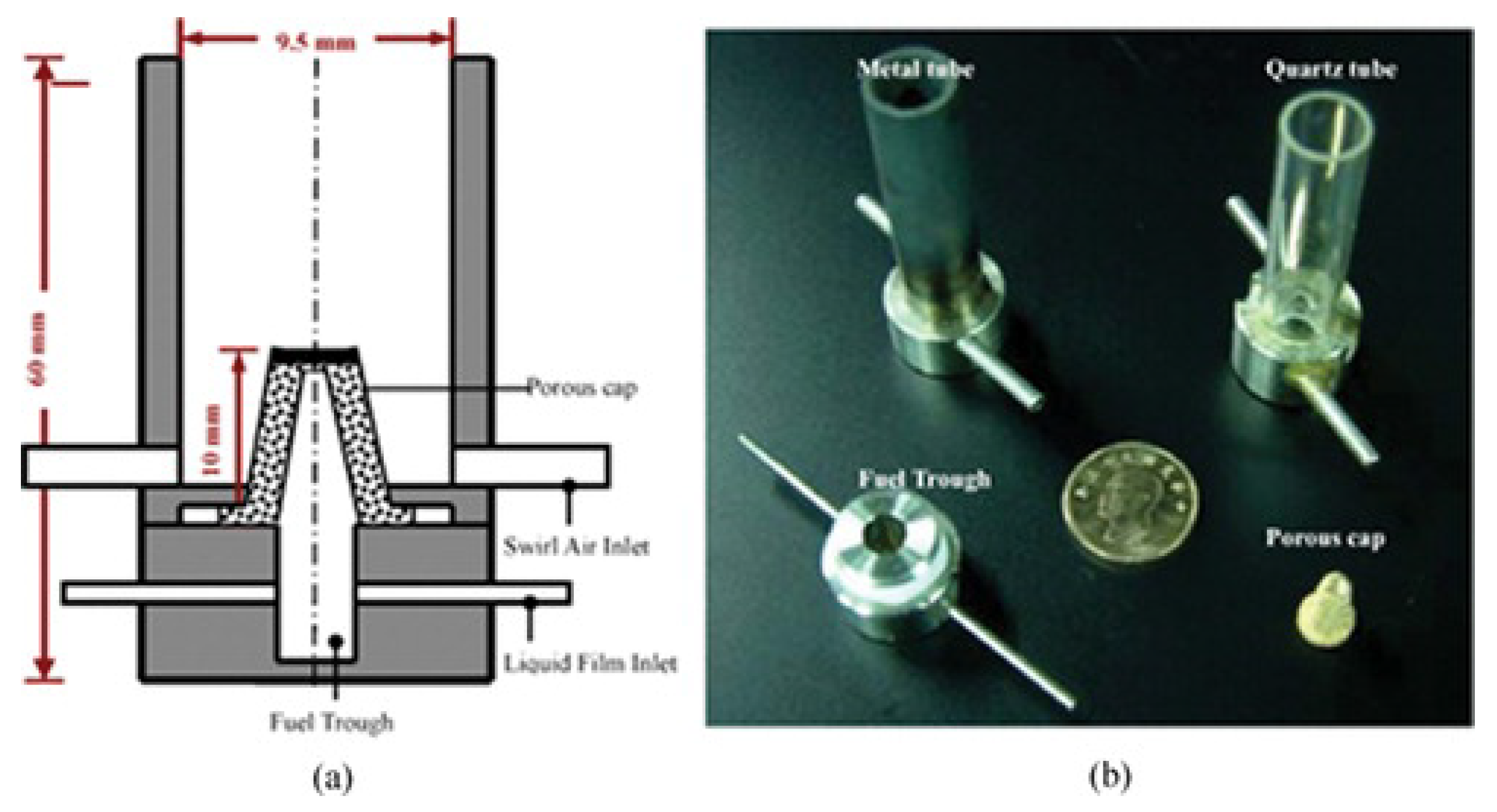
The second design incorporated a porous cap within the core of the combustor. Thus generating a fuel film which can be subsequently transformed into vapour through direct contact within the porous medium by utilizing heat from the combustion products. Figure 9 shows the fuel film combustor with a porous insert. As the air enters the cylindrical chamber with a swirling motion, this facilitates the intake of liquid fuel. A fuel film can be generated and subsequently transformed into vapour through direct contact within the porous medium by utilizing heat from the combustion products. Figure 10 depicts the vaporization and combustion strategy in the fuel film combustor with a porous insert.

2.3. Electrospray

Electrospray technology involves the use of electric forces to atomize liquid fuel into small droplets. The electrospray atomization technology operates by introducing the liquid fuel into a charged capillary at a specific flow rate. Due to various factors such as surface tension, electric stress, and viscosity stress, the liquid will form a stable conical structure at the capillary outlet. At the tip of this conical structure, a small jet is created, which eventually breaks down into a cluster of tiny droplets. The electric field propels these droplets forward as they continue their trajectory [35].

2.4. Porous Medium

Porous media possesses unique characteristics such as a large specific surface area, excellent heat transport capability, and permeability to flow, which makes it a promising material for supporting liquid fuel combustion processes in compact combustors [36,37]. The high specific surface area of porous media provides a large number of active sites for the combustion reactions to occur, leading to efficient and complete combustion of the fuel. The interconnected pore structure of porous media also allows for efficient heat transfer between the solid material and the fluid flowing through it, by promoting convective heat transfer. The permeability of porous media enabled the efficient flow of both fuel and air, thus promoting uniform combustion and reduction in emissions. By virtue of the excellent heat transport properties of porous media, it can also facilitate heat recuperation, leading to more compact and efficient combustion systems. In summary, the unique properties of porous media make it a promising material for its improved combustion efficiency, reducing emissions, and increased feasibility for more compact and efficient combustion systems to be fabricated [38,39]. Table 3 shows the application of porous medium in a micro/meso scale combustor utilizing liquid fuels.

2.5. Miscellaneous Designs

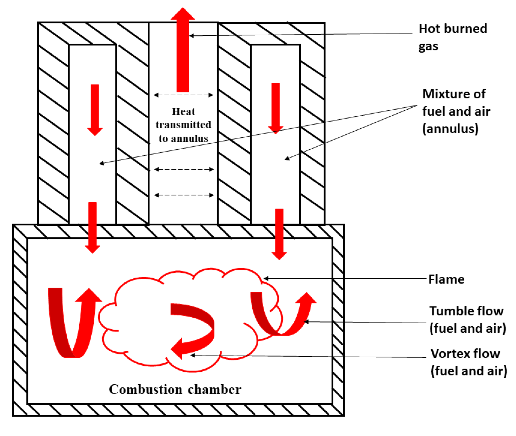
In addition to the injector, fuel film, electrospray and porous medium methods, researchers have made a lot of other attempts to develop a liquid-fueled micro/mesoscale combustor. Majid et al. [43] have developed a miniature combustor and demonstrated the possibility of achieving stable combustion of liquid fuel, by leveraging the vortex motion of the flow. The vortex flow greatly improves the convective heat transfer between the hot gas and the combustor wall [44,45]. Majid et al. [43] have utilized the concept of the reversed vortex, for the combustor consisting of two parts with a concentric tube at the top and a single tube at the bottom as shown in Figure 11.
The annulus of this miniature combustor has a sealed top and the air and fuel were injected into this annulus tangentially. This tangential injection created a vortex motion to the fuel and air mixture and it progressed towards the single tube bottom part. Here the mixture was undergone flow expansion and tumble flow due to the larger diameter of the bottom tube and the change in the flow direction. Flow expansion and tumble flow improved fuel-air mixing as well as residence time, as a result of which the flame gets anchored at the bottom [43]. The burned gas escaped through the central hole transferring heat to the fuel inside the annulus. Asad et al. [46] developed a self-aspirating, pump-free, liquid fuel micro-combustor. The fuel flow into the micro-combustor was achieved by utilizing the effect of hydro-static pressure. The experimental setup comprised of a mini fuel tank (30 mL), stainless steel capillary (150, 260 and 400 μ m), and an ON/OFF flow valve. Figure 12 shows the self aspirating setup, developed.

3. Combustion

Researchers have examined miniature combustors, those working on liquid fuel and operating under different modes of combustion. However, small-scale combustors do have the significant drawback of having a large surface area to volume ratio, which subsequently leads to considerable heat loss, which poses a significant challenge. In this section, we will explore the investigations carried out by researchers on miniature combustors utilizing liquid fuel under different modes of combustion.
Kyritisis et al. [47] developed a novel liquid fuel (JP-8) mesoscale catalytic combustor that employed a series of catalytic grids and multiplexed electrosprays for effective liquid fuel dispersion. Figure 13 represents the schematic representation and presents an overview of how the burner functions.
The combustor design incorporated a sequence of metal grids, which are coated with a catalyst. The grids served as condensed catalyst reactors to initiate and stabilize combustion as well as improve conversion. It also functions as a ground electrode for electrospray. Fuel was introduced by electrospraying, with a flow rate of about 10 g per hour, and equivalence ratios ranging from 0.35 to 0.70. The combustion efficiency and CO emissions were analyzed using n-dodecane as a surrogate fuel, which is the most abundant liquid hydrocarbon in JP8. The study found that the combustion efficiency exceeded 97% and the burner achieved diesel fuel combustion without soot formation. The CO2/CO mole ratio was used as a measure of combustion efficiency, and high values indicated efficient conversion, highlighting the importance of catalytic combustion. The CO emission was found to have an optimum conversion achieved for an equivalence ratio of approximately 0.48. The operation of the burner was completely suspended for equivalence ratios above 0.70 and below 0.25, likely due to variations in airflow affecting residence time in the vicinity of the catalyst. The temperatures at the catalyst ranged from 900 to 1300 K, with uniformity of ±5% over its surface. Figure 14 depicts the variation of CO mole fraction and the ratio of CO 2 and CO on a molar basis w.r.t equivalence ratio ϕ . The burner generates a surface with an even distribution of heat, which is optimal for integrating with energy conversion modules that operate at the desired temperature.
The electrospray capillaries are not self-sufficient devices, as they necessitate a direct current voltage in the range of several kV. Yuliati et al. [48] reported that the power requirement for electrospray generation was 13 mW. Gan et al. [49] developed a new small-scale combustor with an electro-spraying system that used liquid ethanol as fuel. The experiments demonstrated the successful application of the electro-spraying technology in the combustion system and identified different spray modes including pulsed-jet, cone-jet, skewed cone-jet, and multi-jet using optical visualization. Figure 15 shows the flame images for different conditions of flow rate using an electrospray [49].
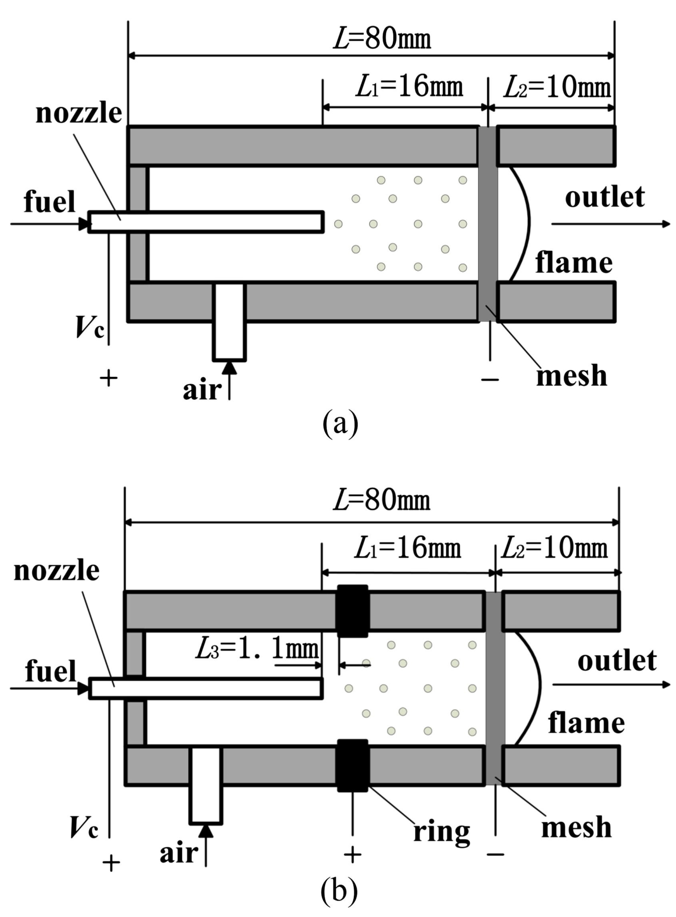
The study also divided the operating ranges of the different electro-spraying modes for ethanol based on experimental results. The driving force for droplet motion was found to be mainly from the electrostatic induction field between the nozzle and the steel ring, with the electric field between the steel ring and steel mesh providing a driving force for droplet motion in the spraying region. The Taylor angles measured for the cone-jet mode were within the range of 75 . 18 to 82 . 45 . The specific charges of electro-spraying ethanol were highest in the cone-jet mode, which provided another way to differentiate between the different modes. Gan et al. [50] investigated the electro-spraying of ethanol in two types of mesoscale combustors that differed in electrode designs. Four different spraying modes were observed, and the results revealed that the additional ring electrode design in the Type B combustor improved the uniformity of the electric field in the spraying region. As the electric field increased, the droplet size decreased. Figure 16 shows the schematic of mesco-sclae combustor designs.
The combustion study of ethanol Figure 17 in both combustors revealed that the smaller and more uniform droplets in the Type B combustor facilitated fuel/air mixing, reduced heat loss and soot formation, and improved the combustor’s performance.
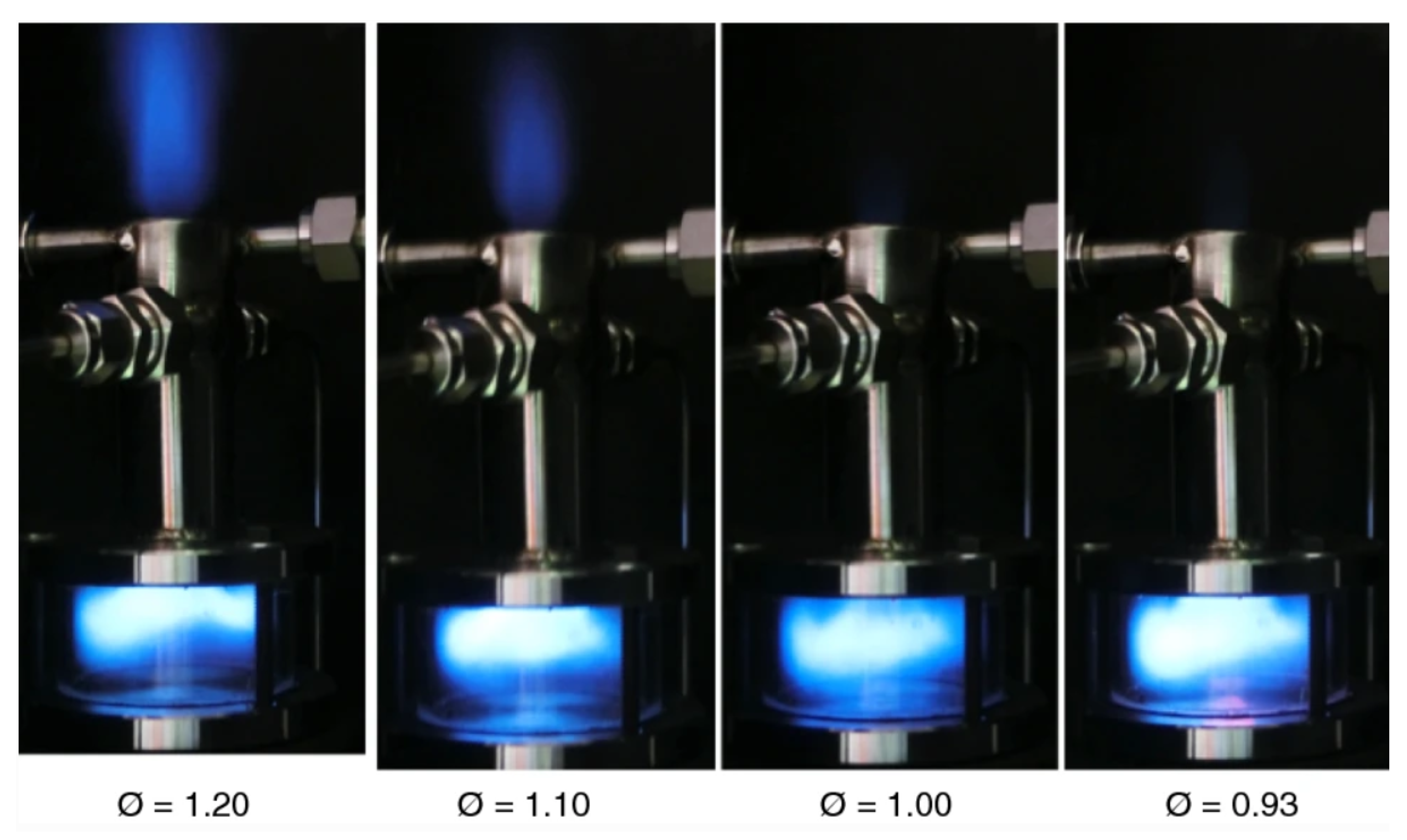
The study demonstrated that the new electrical spray design with an additional ring electrode, reduced droplet size and improved uniformity of size distribution and thereby significantly impacting the performance of mesoscale combustors. Gan et al. [51] investigated the combustion characteristics of ethanol using an electrospray technique in two meso-combustors with and without a Pt catalyst (Combustor A and combustor B respectively). Four spraying modes were identified, with the cone-jet mode found to be suitable for ethanol combustion. The Pt catalyst improved combustion efficiency and reduced CO emissions by at least 25%. The combustion efficiency was improved by 4.5% for combustor B, indicating the catalyst’s significant role in enhancing the combustor’s performance. Gan et al. [52] developed a mesoscale electrospray combustor working on ethanol coupled with an energy conversion module. The combustor was found to sustain stable flames within a range of equivalence ratios from 0.9 to 1.7. The mesh structure of the combustor served as both a collector for charged droplets and a flame holder. Figure 18 shows the flame structure infrared image of the wall for different equivalence ratios.
The heat re-circulation was observed under all experimental conditions, which was found to enhance the fuel evaporation process. The thermal efficiency of the combustor was observed to vary between 22.0% and 48.8%. The maximum values for flame temperatures, heat losses, combustion efficiencies, and thermal efficiencies were all observed at an equivalence ratio of 1. Yuliati et al. [48] investigated the feasibility of stable burning conditions inside a narrow tube through the implementation of the electrospray method, without requiring any external heating or a catalyst. The fuel used in this study contained 30% ethanol and 70% n-heptane by volume. Stable combustion was achieved through the utilization of the electrospray technique with a single capillary-ring extractor-mesh collector electrode configuration. For a fuel flow rate of 1 mL/h, a steady flame was successfully established inside the tube without wetting its walls and within a certain range of equivalence ratio. Figure 19 shows the schematic of the micro-combustor, images of electrospray and flame inside the narrow tube and the axial droplet velocity distribution.
Jiang et al. [53] experimentally investigated the combustion characteristics of bio-diesel ethanol blends in a mesoscale combustor utilizing the electrospray technique. The addition of ethanol reduced droplet size and improved spray angle, among which BE40 showed the best combustion performance with reduced CO and soot emissions. The method of blending ethanol with electrospray was observed feasible for improving bio-diesel characteristics, but further optimization is needed for practical applications. Figure 20 shows the flame structure of bio-diesel ethanol blends in the mesoscale combustor.
Sadasivuni et al. [20] developed a combustion system using liquid fuels which included a flow-blurring injector, a counter-flow heat exchanger, and a porous medium to achieve a stabilized combustion. The system achieved a high volumetric energy density and produced a clean, compact, as well as flat flame without soot. The majority of the heat released was retained by the products, with only a small amount lost to the ambient. The system maintained good performance over a range of air and fuel flow rates, and numerical results accurately predicted its thermal performance and flame structure. Figure 21 shows the flame stabilized over the porous medium in the combustor.
In order to resolve the challenge of achieving effective atomization at low fuel flow rates, several approaches have been introduced, such as fuel film and evaporation [24]. The fuel-film concept is able to potentially reduce heat loss and optimize vaporizing surface area in miniature-scale liquid-fuelled combustors while inhibiting quenching.
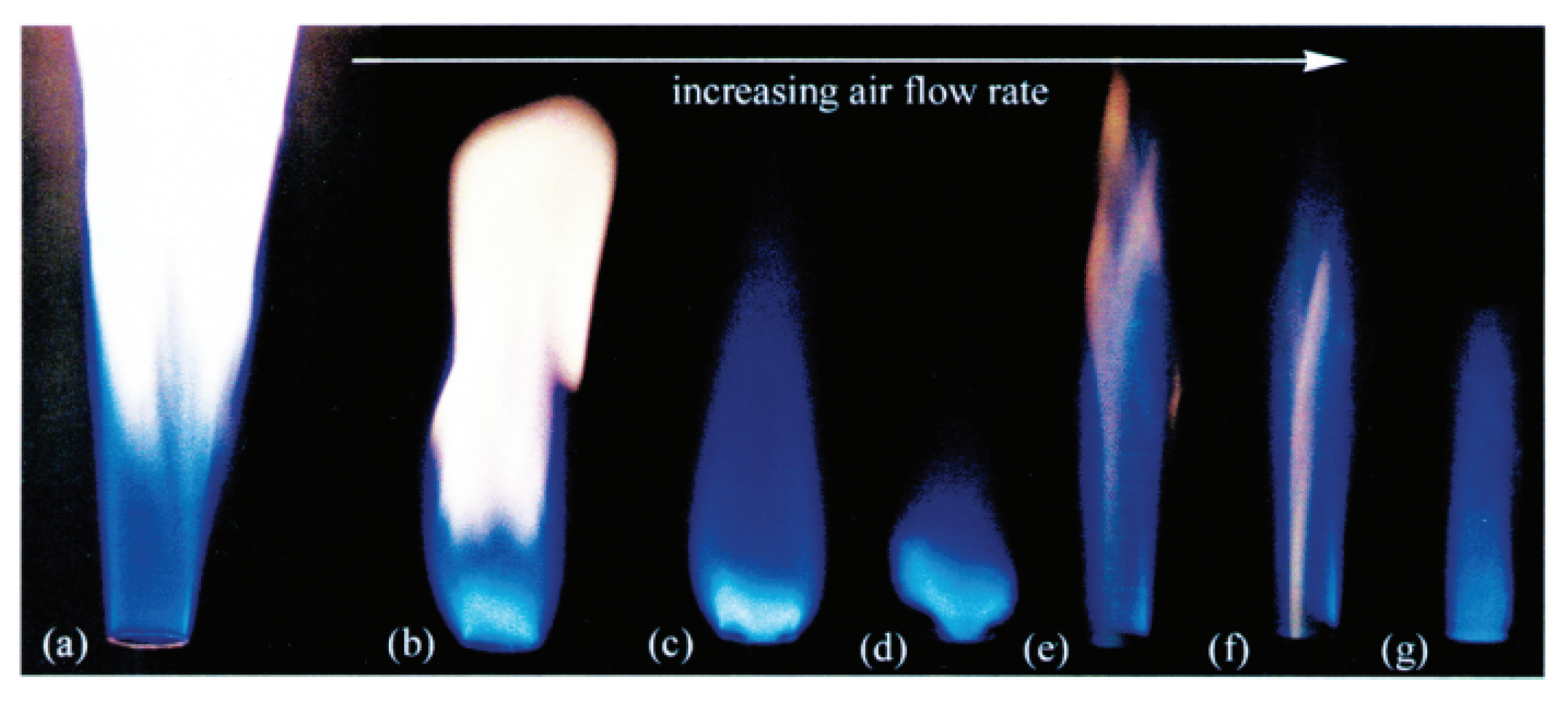
Figure 22 shows a methane gas flame with a spiral swirler and Figure 23 shows methane plus liquid methanol fuel film flame. It was observed that the methanol flame required the addition of gaseous methane fuel for stability, whereas the heptane fuel burned successfully on its own, Figure 24. The experimental results showed that a pure gas fuel flame with a weak swirl could not sustain an internal flame, whereas liquid gas blends and pure liquid flames could.
This difference in behaviour was attributed to variations in flame dynamics, mixing, and heat loss, indicating the importance of swirl in flame stabilization. Stanchi et al. [54] investigated the benefits of operating a combustor at elevated pressure using a liquid fuel film combustor. It was observed that at atmospheric pressure (without nozzle) with the original configuration of air injection (internal diameter of 3.3 mm), it couldn’t produce enough swirl to stabilize the flame. The air injection internal diameter was then modified to 0.9 mm and tested for different fuel-air flow rates. Experiments revealed that pure tangential injection gives a weak mechanism of flame stabilization and introducing swirl vanes Figure 25 can solve this issue. These swirl vanes along with the tangential injection increase the tangential momentum and create a wake that could anchor the flame.
Pham et al. [33] proposed a liquid fuel film miniature combusting using n-heptane as the fuel Figure 26.
Experiments were mainly performed in a steel tube combustion chamber with air injected tangentially at two points and liquid heptane fuel injected downstream via stainless steel capillary tubes. The fuel injection rate was 9.7 mg/s and equivalence ratios ranged from 1.4 to 2.2. Figure 27 depicts the temperature measurements taken above the chamber rim and it suggests that the flame is partially premixed, with near stoichiometric conditions along the central axis and very rich regions near the walls.
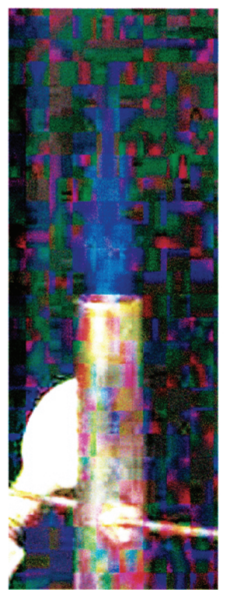
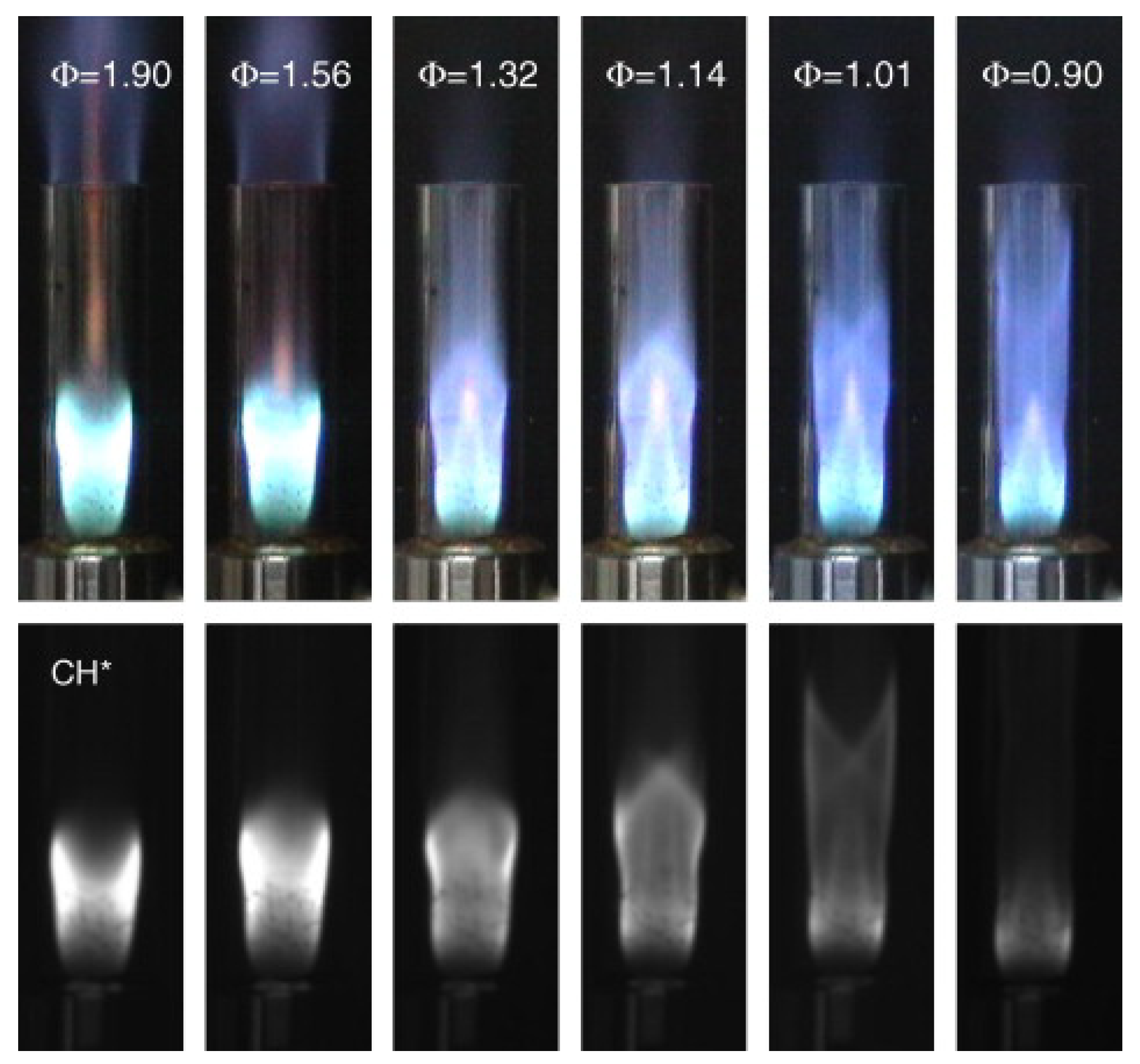
To further explore the flame structure and fuel film flame stabilization mechanism a quartz chamber with the same dimensions as the metal chamber was constructed. Due to the low thermal conductivity of quartz, there was a noticeable difference in operation as compared to the metal chamber. The quartz chamber study revealed the presence of two separate flame structures a rim flame and a central triple flame as shown in Figure 28.
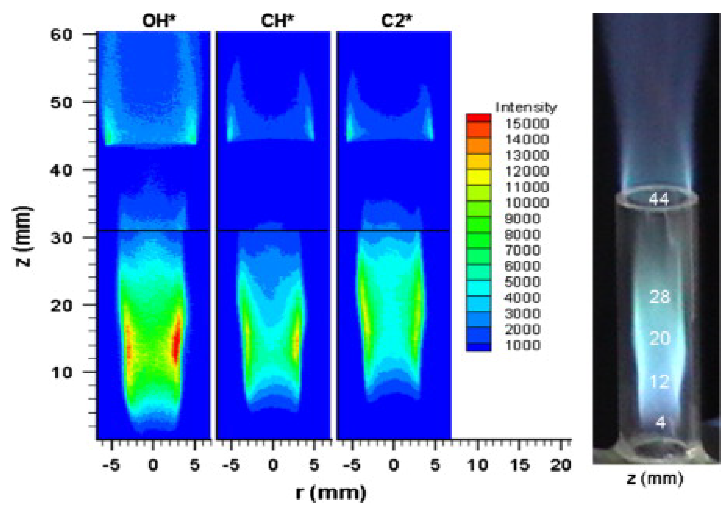
The heat transfer issues associated with quartz could be solved by using a more thermally conductive material like sapphire. The flames were examined using chemiluminescence of OH∗, CH∗, and C2∗. Chemiluminescence study Figure 29 revealed the presence of richer regions near the wall and leaner regions in the centre, this is in line with the flame’s structure theory. Furthermore, the images obtained verified the distinct nature of the two flames.
Liquid fuel film combustors can benefit from utilizing a metal-porous medium as it can enhance contact surface area and heat transfer for fuel vaporization and flame stabilization. A mesoscale combustor with a central porous inlet has been introduced by Li et al. [55], shown in Figure 30.
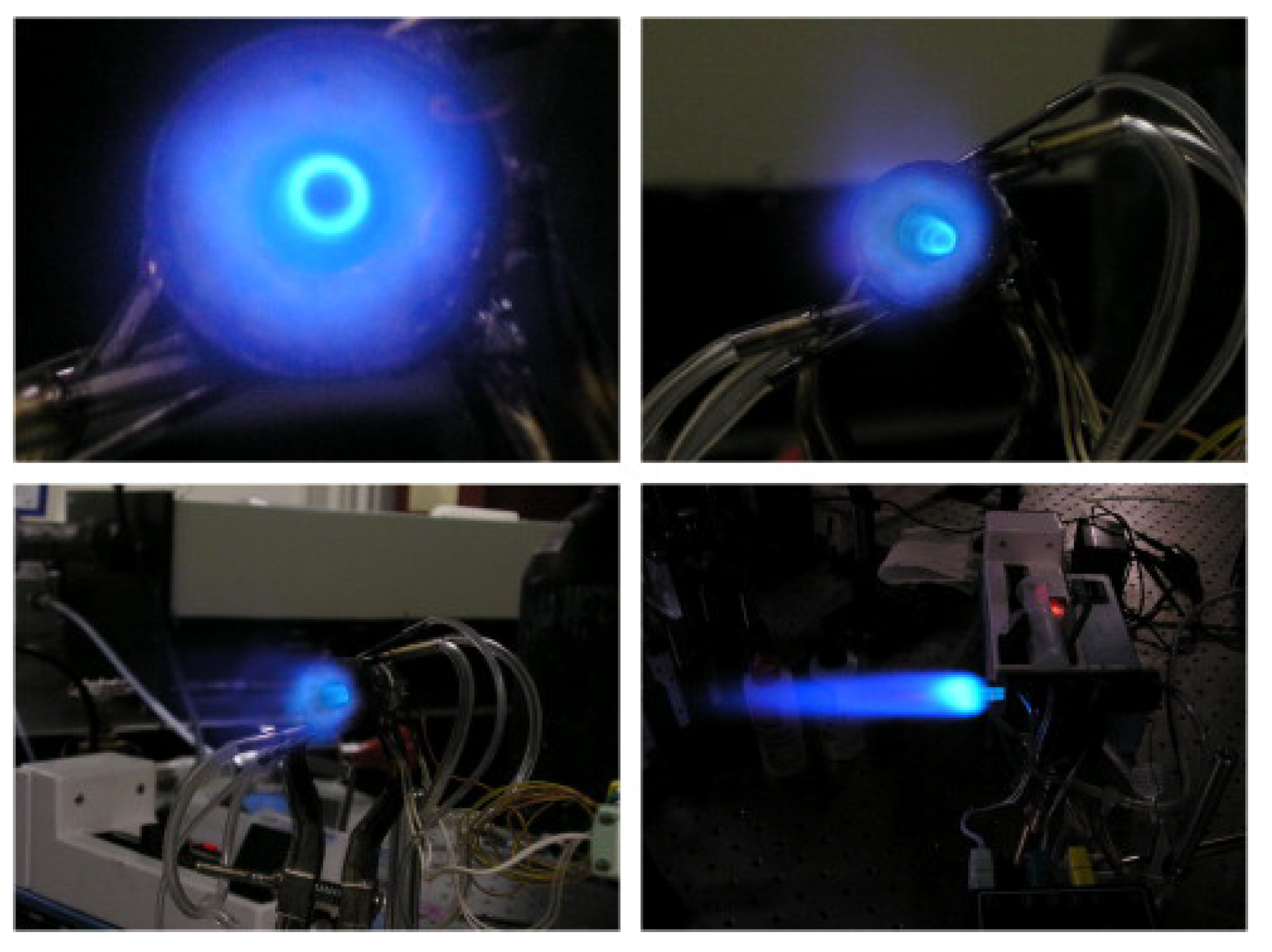
The study investigated the impact of different types of porous materials (stainless steel and bronze) [40] and bead sizes on flame structures and combustion characteristics of heptane flame. There are distinct differences in the stabilization mechanism and flame structure observed between the two types of porous media combustors made of stainless steel and bronze. The flame structure of liquid fuel film combustor with bronze porous medium insert consists of two layers Figure 31. An inner flame that serves as a pilot flame, and an outer flame that behaves like a swirl flame. With the increase in air flow rate, there was no noticeable difference in the flame anchoring and structure.
In the case of a fuel film combustor with stainless steel porous insert, the flame takes on a swirl shape and attaches itself to the lateral surface of the cap as well as the tube exit Figure 32. With the increase in air flow rate, the flame front at the exit shifts upstream, and the red-hot spot on the stainless steel cap becomes larger and brighter.
Figure 33 display the radical concentration of OH∗, CH∗, and C 2 ∗, along with the corresponding flame image for a fuel film combustor with stainless steel porous cap.
Near the porous surface, the flame forms two distinct layers—one along the porous cap and the other along the wall. C 2 ∗ radicals are concentrated in both layers, with a peak concentration along the wall, indicating highly rich zones. On the other hand, the OH∗ concentration is highest near the wall, revealing the primary reaction zone in that region. The CH∗ radicals are concentrated near both the wall and the porous medium. Figure 34 displays the radical concentration of OH∗, CH∗, and C 2 ∗, along with the corresponding flame image for a fuel film combustor with bronze porous cap.
Figure 34 shows that OH∗, CH∗, and C 2 ∗ radicals were present in two flame layers above the porous cap. Above the porous cap, a fuel-rich flame got separated from the base of the diffusion flame to form a pilot flame. The effect of bead size used in a porous medium didn’t have a significant change in the flame structure and anchoring position. However the stable operating range of the combustor got reduced as bead size increased. Li et al. [34] introduced the concept double wall chamber for liquid fuel film combustors. The modified combustor was tested with methanol and heptane. Experiments on methanol/air combustion showed ignition problems due to methanol’s high latent heat of vaporization. Preheating with a torch was necessary for some conditions. Quenching was also a problem. Temperatures were measured at different locations as shown in Figure 35A. On the internal wall, it was shown a film’s presence. Higher temperatures were measured near the exit due to conduction from the flame to the walls. Figure 35B shows the methanol flame and Figure 35C depicts the temperature profile across the combustor.
Heptane was found to be a more suitable fuel than methanol for improving the mixing rate in a double-wall combustor, as it has a lower heat of vaporization. Combustion within the device is stable and self-sustained for rich mixtures, but unstable for an equivalence ratio of 1. It was observed that as the equivalence ratio increased, the flame became more stable with occasional perturbations. Figure 36 shows the heptane air flame in a double wall fuel film combustor. The double-wall combustor was found not to be suitable for lean mixtures owing to its long and narrow design that hinders ignition flame from reaching the bottom. Flame quenching happened when n-heptane was burned at equivalence ratios between 0.8 and 0.95. At an equivalence ratio of 3, liquid fuel escaped from the exit which subsequently resulted in a large and sooty plume.
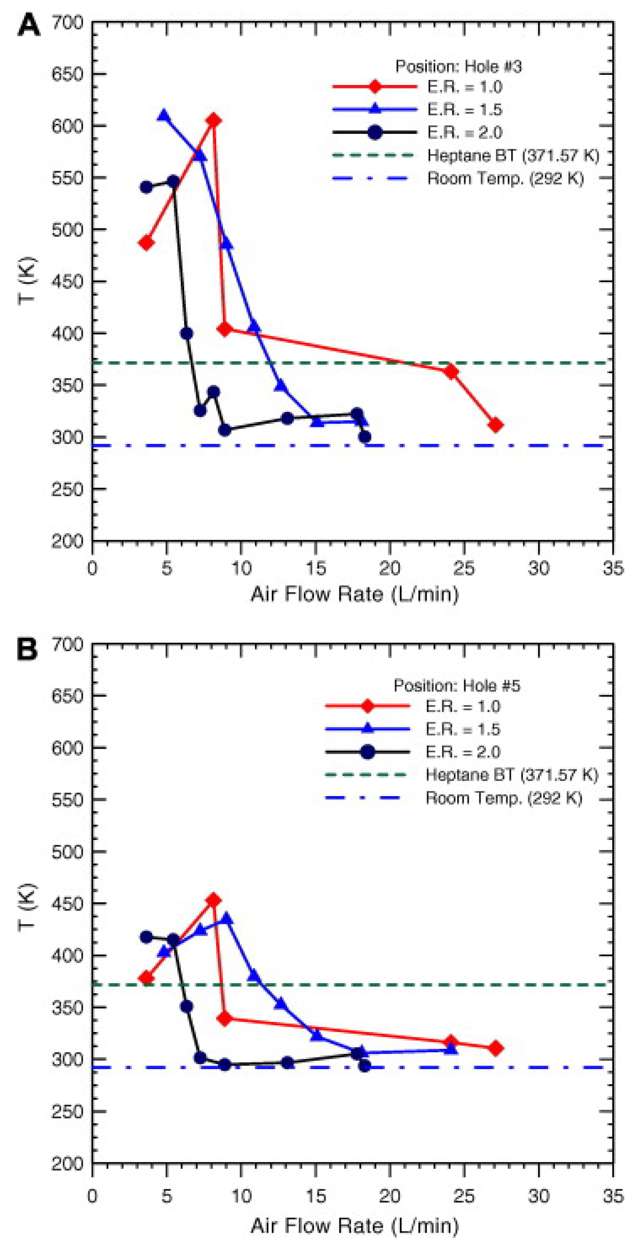
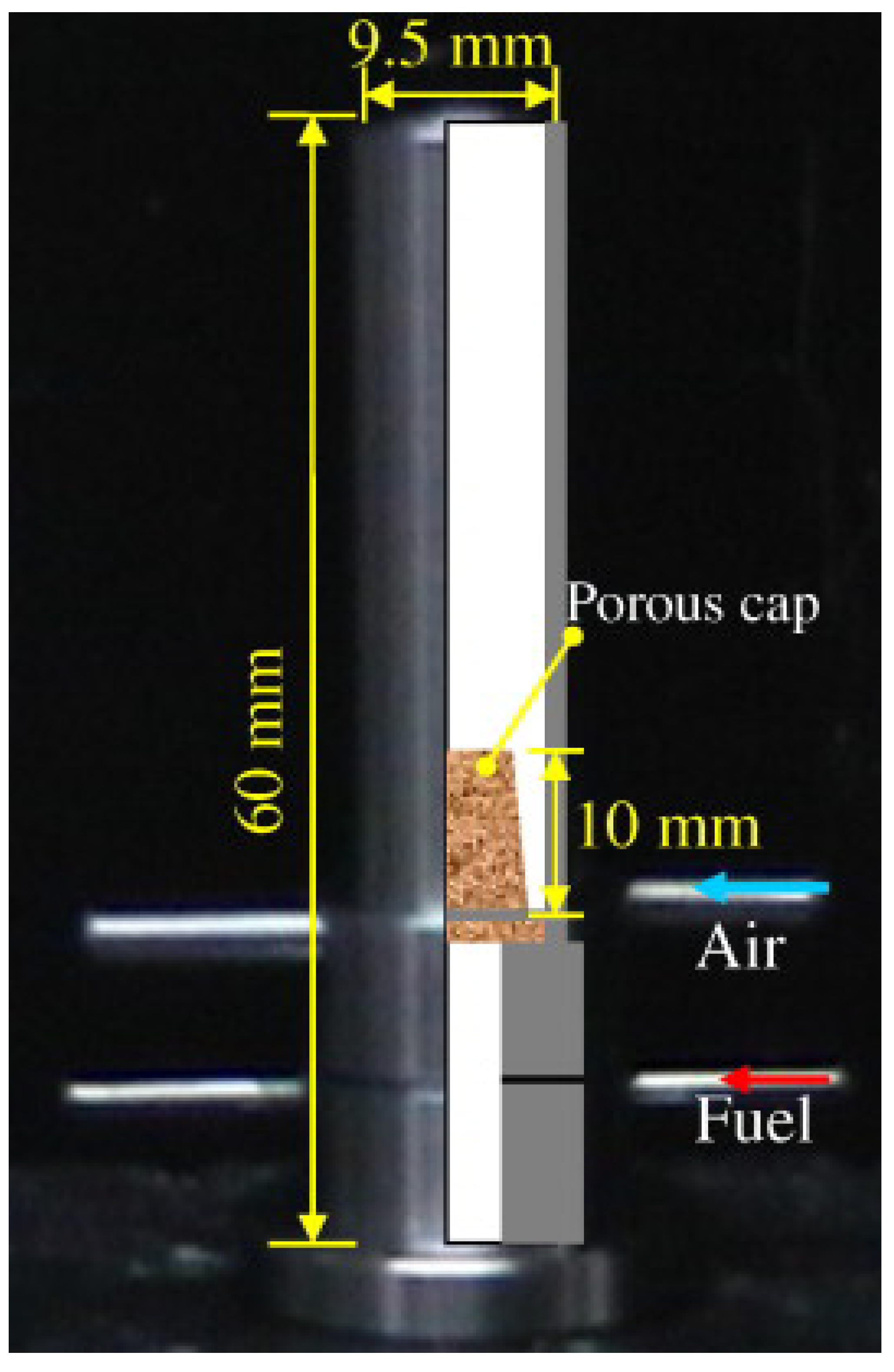
The temperature profile outside the inner wall of the combustor revealed that the temperature was mostly above the n-heptane’s boiling point at an equivalence ratio of one, except at high flow rates. Figure 37 shows the temperature profile outside the inner wall at different air flow rates. Li et al. [34] introduced the central porous fuel insert concept to fuel film combustors. The combustor was tested with n-heptane fuel.Combustor configuration is depicted in Figure 38. An experimental study revealed that the airflow rate has a significant impact on flame characteristics. Low swirling flow resulted in the flame anchoring either on the porous cap or on the rim of the chamber exit. Stronger swirls forced the flame into the chamber where it undergoes a reaction. The use of CH∗ chemiluminescence helped in observing the main reacting zone of the flame. Figure 39 shows the flame structure inside a fuel film combustor with a central porous insert.
The material of the porous medium is crucial for efficient combustion in the central plug combustor design. The conductivity and porosity of the medium have significant effects on temperature. Figure 40 shows the effect of porous material and pore size used in the central porous insert fuel film combustor.
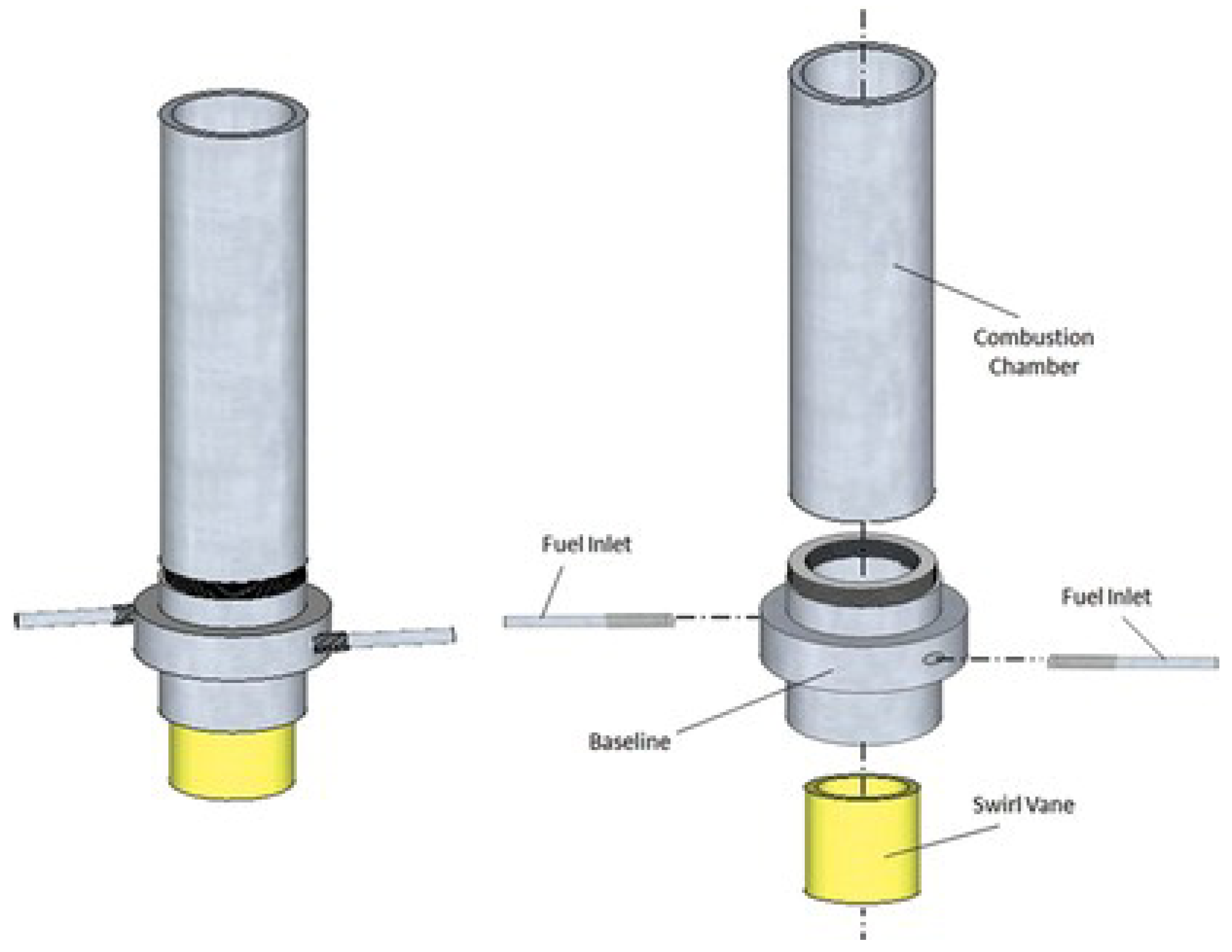
Stainless steel possesses low conductivity, which consequently results in the heating of the porous cap, while bronze has high conductivity and reduces combustion oscillation. Large pore-size media were observed to be sensitive to perturbations, while small pore-size media carried away heat but required excess fuel for cooling. The central porous fuel inlet combustor was able to be operated stably in the fuel-rich regime, especially at high Reynolds numbers. Giani et al. [56] studied the effect of swirl vane design on liquid fuel film (n-heptane) combustor by maintaining the tangential fuel inlet with the addition of swirl vanes at the bottom. The schematic of the modified combustor is shown in Figure 41. In this study effects of different swirl, vane designs were tested.
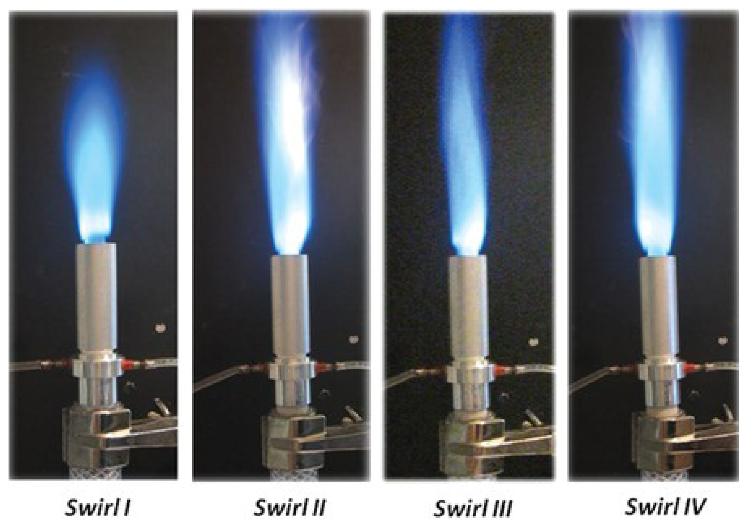
Figure 42 shows the stable flame of an aluminium combustor with different swirl vane designs. The aluminium combustors showed superior flame stability over the stainless steel combustors irrespective of the swirl vane designs. The aluminium combustion chamber had a relatively mild temperature gradient throughout its surface, reaching its maximum temperature below the boiling point of the fuel. On the other hand, the stainless steel chamber displayed a sharp temperature gradient, with surface temperatures surpassing the fuel boiling point for the majority of the chamber’s length. This thermal behaviour corresponded with the earlier research on the film combustor using tangential air injection. Swirl vanes generated a strong swirling flow, promoting mixing and fuel film creation, and enhancing vaporization rates through increased heat transfer to the film.
Silva et al. [57] introduced the concept of secondary injection to liquid fuel film combustor. The modified design allowed for complete combustion and better flame stability. With the introduction of secondary injection a lower wall temperature was obtained. The wall temperature profile with and without secondary injection is, as depicted in Figure 43.
Sauer et al. [58] developed a liquid-fuelled swirl type tubular burner, in which the fuel was injected through the permeable walls of the combustion chamber. Figure 44 shows the schematic diagram of the liquid-fuelled porous wall combustor.
The burner consisted of two concentric tubes, with liquid fuel flowing through the permeable inner tube and the air got injected from the bottom through a swirl generator. The flame structure inside the combustion chamber couldn’t be easily observed due to the presence of a porous matrix. Hence, externally observable quantities such as the flame structure above the burner rim, outer wall temperature, and liquid fuel level in the annular space were used. It was found that at lean fuel inlet conditions, the flame shape changed from tubular inside the combustion chamber to an inverted conical shape above the burner rim. However, both regions appeared to be part of the same flame structure as there is no visible discontinuity between them and when the fuel inlet condition was rich, a secondary flame is formed above the burner rim due to the reaction of the unburnt gas mixture with the ambient air. The working limit map of the combustor is shown in Figure 45.
Chen et al. [36] proposed a self-evaporating mesoscale burner using n-heptane as the fuel. The combustor incorporated a porous medium through which the fuel was injected. The schematic of the experimental setup is shown in Figure 46.
The combustion characteristics of n-heptane, ethanol and dodecane were studied in a burner by monitoring porous medium temperature and flame with and without external heating. Initially, the burner was preheated by an electric heater and then liquid fuel was injected into the porous medium. After some time, the heater was turned off and a self-sustained flame was obtained in the burner. Despite the continuous injection of room temperature fuel, the temperature of the porous medium remained higher than room temperature owing to the high temperature obtained from the flame. The length of the externally heated flame was observed to be larger than that of the self-sustained flame. The temperature of porous media near the fuel outlet was found to be playing a crucial role in the stability of the flame. And it was also noted to be greatly influenced by the airflow. A larger fuel flow rate as well as maintaining the porous media temperature at less than the boiling point was able to prevent the flame from oscillating or extinction. It was also found that varying air flow rates changed the global equivalence ratio and evaporation, which subsequently altered the flame shape. At 150 μ L/min fuel flow rate, flame length was observed to be initially increasing and then decreasing as the air flow rate changed from 0.4 to 2.0 L/min. The optimal air flow rate was determined to be 1.9 L/min with 0.93 combustion completeness. Increasing the temperature of the porous medium near the fuel outlet affected fuel evaporation and velocity, which in turn increased the flame length and soot if the temperature is lower than the boiling point. However, when the porous medium temperature was higher than the boiling point, improving the temperature had very little effect on the flame shape. Figure 47 shows the flame structure of ethanol, n-heptane, and dodecane flame.
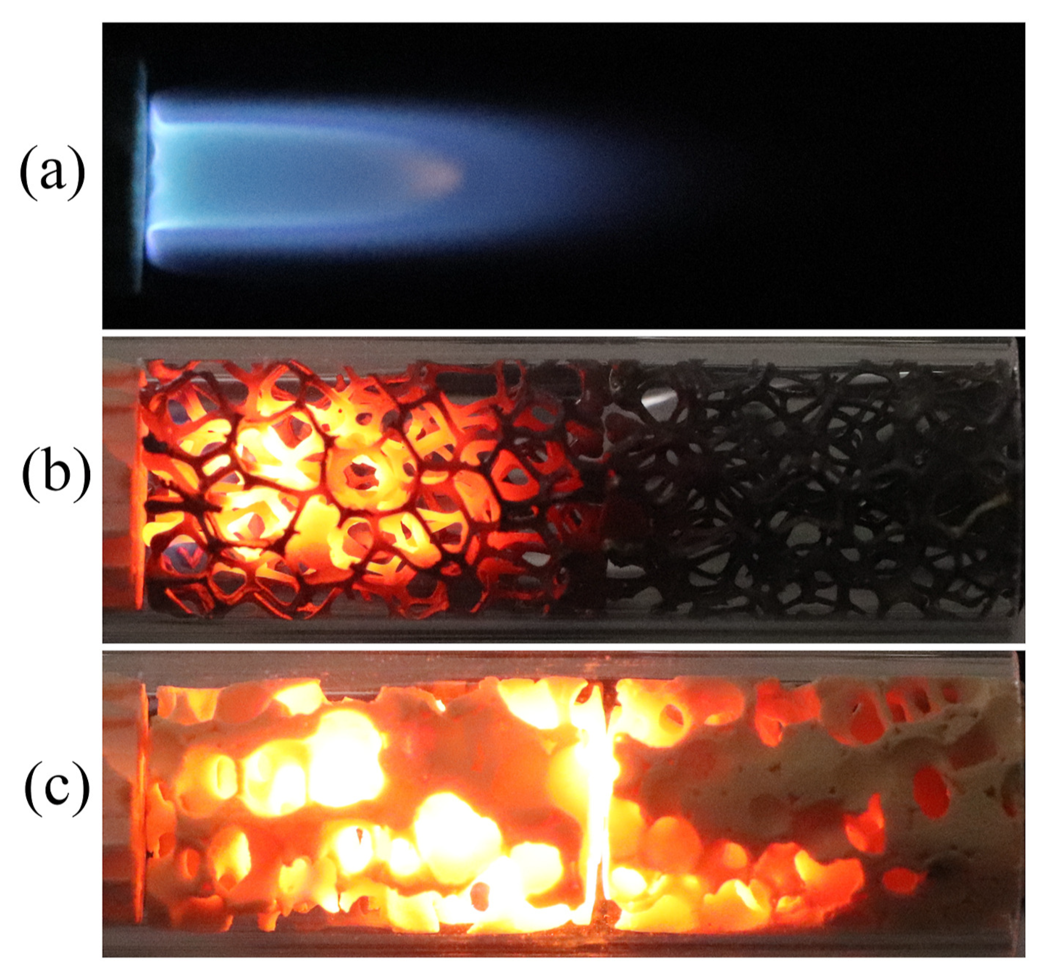
In low-temperature porous media, n-heptane has better evaporation performance than ethanol and dodecane, and self-sustained combustion can be achieved. Ethanol and dodecane can evaporate completely with external heating and result in stable flames. Chen et al. [42] investigated the characteristics of the flame front in a porous medium and provided insights into the flame stability mechanism at the pore-scale of three different burners namely a free flame burner (FF burner), a submerged flame burner with nickel foam (NI burner), and a submerged flame burner with zirconia foam (ZRO burner). Figure 48 shows the flames in different burners.
The study found that the blue flame front moved intermittently within the nickel foam, with a maximum instantaneous flame speed of 6.519 mm/s and an average speed of 0.225 mm/s, as indicated by a rapid rise in temperature. Furthermore, the use of a porous medium resulted in reduced temperatures in the reaction zone and exhaust gas, improved wall temperature, and a brighter combustion zone. In addition, the submerged combustion had low NO x emissions. Finally, the study revealed that the addition of a porous medium significantly enhanced the radiant intensity of the mesoscale burner, and the submerged flame’s heat transfer efficiency (twice that of the free flame).
Junwei et al. [59] studied the diffusion flame characteristics of n-heptane fuel in a small quartz tube with an ID of 4 mm and OD of 6 mm. The study investigated the effect of heat recirculating, the schematic of the setup is shown in Figure 49.
The location and temperature of a diffusion flame in a tube burner without heat re-circulation were affected by air velocity and heat loss coefficient. However, a tube burner with heat re-circulation could be operated stably at higher Reynolds numbers and heat loss coefficients, although the shape and position of the flame might be varied. Furthermore, the flammable limits of a burner with heat re-circulation increased significantly with an increase in the heat loss coefficient compared to a burner without heat re-circulation. In the case of a liquid fuel diffusion flame, the flammable limits of stable operation were increased as the fuel flow rate increased. In a small straight tube, the diffusion flame had a tendency to move downstream as the airflow rate increased and eventually got stabilized at the bottom of the outer tube. During flame propagation in the tube, the temperature peak occurred on the tube wall, which then gradually decreased. When heat re-circulation was present, the inner tube wall temperature remained higher than the boiling point of liquid n-heptane, promoting pre-evaporation of the fuel. However, without heat re-circulation, liquid fuel might get accumulated in the tube. Li also studied the effect of adding porous medium to a meso scale burner [41]. Figure 50 shows the schematic of the experimental setup.
A burner without porous media might experience oscillation and become vulnerable to external factors, eventually leading to the flame getting extinguished. It was observed that increasing the equivalence ratio while maintaining a constant airflow rate could reduce the amplitude of the flame temperature and increase the oscillation frequency. It was reported that at lower airflow rates, the flame was able to get stabilized on the surface of the porous media while increasing the airflow rate can move the flame toward the exit of the inner tube. It was found that the position of the porous medium affects the stability of the flame and facilitates the evaporation of liquid fuel. The outer tube of the burner also played an important role in preheating the fuel and air, which eventually improved the flammability limits. Junwei et al. [60] studied the effect of heat re-circulation on micro combustors with different thermal insulations. Three different combustors were studied, which are a quartz tube combustor with an inner diameter of 4 mm (CS), a micro combustor with one layer heat recuperator (CA) and a micro combustor with vacuum insulation (CB). Figure 51 depicts the schematic of a micro combustor with different thermal insulations.
In a quartz tube combustor without heat re-circulation, wall heat loss caused the flame to easily blow out. However, heat re-circulation could stabilize the flame and reduce wall heat flux. The introduction of the vacuum insulation tube was able to further reduce wall heat loss and increase preheating which in turn lead to higher combustion efficiency in fuel-rich conditions. Additionally, a re-circulation tube can greatly increase the amount of heat recovered from combustion. Junwei et al. [61] incorporated a porous medium to disperse droplets on an n-heptane-fuelled micro combustor with an outer tube to recirculate exhaust heat. Heat re-circulation was found to increase wall temperature as well as residence time, which ultimately lead to stable micro diffusion flames. The double-layer outer tube showed the highest wall temperature and lowest outer wall temperature, which reduced wall heat loss and improved fuel evaporation. Radiation heat loss was found to be the biggest contributor to total heat loss. Fuel flow rate was found to affect the flame position and it was also found that stabilizing the flame at the bottom of the outer tube resulted in the highest energy conversion efficiency for micro-power systems. Chen et al. [62] studied the effect of external heating n-heptane fuelled micro porous combustor. External heating could increase the flame stability in a micro-porous combustor. The temperature of the porous medium gradually decreased after stopping external heating, which caused flame oscillation and extinction. The low-temperature oxidation reaction of n-heptane occurs in the porous medium when the temperature is higher than 233.2 C.
Majid et al. [43] studied the properties of combustion inside a newly developed miniature liquid fuel(n-heptane) vortex combustor. The study proposed a unique technique to achieve stable combustion of liquid fuel within the miniature combustor without relying on external heating, spray, secondary injection, or a porous media at a fuel-lean regime. Two key factors influencing stable combustion were identified: heat transfer and re-circulation mechanisms. The burned gas along the inner tube improved the evaporation rate of liquid fuel inside the annulus, while re-circulation preheats the incoming fresh fuel-air mixture from the annulus into the bottom chamber and anchors a stable flame within the miniature combustor.
Figure 52 shows the flame structure in miniature vortex combustor at different equivalence ratios [43] The thermal analysis demonstrated that the vortex motion of the flow enhances heat transfer. Azad et al. [46] introduced a new micro-combustor that uses hydro-static pressure to deliver fuel without the need for a pump, making it energy-efficient and self-aspirating. The combustor was incorporated with porous media to enhance flame stabilization and reduce the risk of blowouts. The system was found to be very easy to integrate, and its fabrication technology was cost-effective for micropower generation. It was actually able to provide continuous power for up to 40 h without requiring additional power to run auxiliary components. This development has the potential to be one of the most significant methods for a wide range of heat and power applications. Figure 53 shows the ethanol flame structure in the self-aspirating combustor.
Bharadwaz et al. [63] developed a novel power generation system, which operates independently and uses liquid fuel. The fuel was evaporated by the heat from the combustor, and the resulting vapour was injected at high speed. This subsequently created a high-momentum fuel vapour jet that entrains ambient air, which was then burned in a small-scale combustor. The hot gases produced by this combustion process were used to heat the hot side of a thermo-electric module, while fins were incorporated to reject heat from the cold side of the module. The entire system had a weight of approximately 800 g and was capable to generate 12 watts of power with an overall efficiency of 2.4%. The system was able to be operated for 1.5 h on a single fuel refill. The power and energy densities of the system are estimated to be 15.4 watts per kilogram and 23.1 watt-hours per kilogram, respectively. Table 4 gives a concise report of the important features regarding liquid fuel micro combustors that have been reported in the literature.

4. Power Generation

Different methods have been developed by researchers to convert the energy produced by combustion to electric power [3]. Thermo-electric generators (TEG) and thermophotovoltaic (TPV) systems are two direct conversion methodologies which utilize the properties of the material to convert heat to electricity. These methods have been implemented by researchers to the miniature combustor to generate power. Li et al. [64] developed a TPV-based power system that uses a liquid-fuel-film combustor with a central porous inlet. Figure 54a,b show the schematic and image of the experimental setup and Figure 54c shows the photograph of the TPV-based power system.
By using a metal-porous medium, they were able to increase the contact surface and heat transfer for liquid fuel evaporation, as well as inhibit flame quenching. To achieve uniform emitter illumination and confine the flame, a reverse tube was introduced. The power output of the TPV cell was dependent on combustion efficiency and emitter temperature. In the prototype design, using n-heptane fuel at a flow rate of 12 mg/s and equivalence ratio of 1.0, an electrical power output of 8.3 watts was achieved, with an open-circuit voltage of 1.81 volts and a short-circuit current of 6.6 amperes. Li et al. [65] also evaluated the performance of the miniature combustion-driven TPV system using GaSb PV cells. The prototype system included a combustor and four PV cell modules, with a maximum power output of 5.84 watts and efficiency of 0.95% achieved at an equivalence ratio of 1.05. Efficiency was further improved to 1.02% by using a porous medium for fuel/air mixing. Jain et al. [66] developed a liquid-fuelled miniature power generation system that utilizes TEG for generating power. This system has a weight of 1.15 kg and can generate 15 W of power, with an overall efficiency of 3% and a runtime of 1 h on a single refill. Bharadwaz et al. [63] developed a TEG-based power generator that uses liquid fuel. The proposed system had a weight of around 800 g and was capable of producing 12 watts of power. Its overall efficiency is 2.4%, and it can handle a heat load of up to 500 watts. The system can operate continuously for 1.5 h with just one refill.

5. Instabilities for Liquid Fuel Combustion at Small Scale

Micro-scale and mesoscale combustion exhibit strong coupling between thermal and kinetic processes which results in significant heat loss. This interaction leads to diverse flame instabilities, which have been studied extensively by various researchers [67,68,69,70], in this section, we discuss different types of instabilities like flame repetitive extinction and ignition (FREI), flame oscillation, explosive flame as reported by researchers with respect to the liquid fuel combustion at small scales.
Chen et al. [71] observed flame repetitive extinction and ignition (FREI) in an n-heptane-fuelled foamed porous media combustor. Flame pulsation was observed to be closely related to the local solid temperature, when the flame entered a cell with low solid temperature, the wall quenching effect caused it to stop propagating. Figure 55 shows the process of flame pulsating in a porous media combustor.
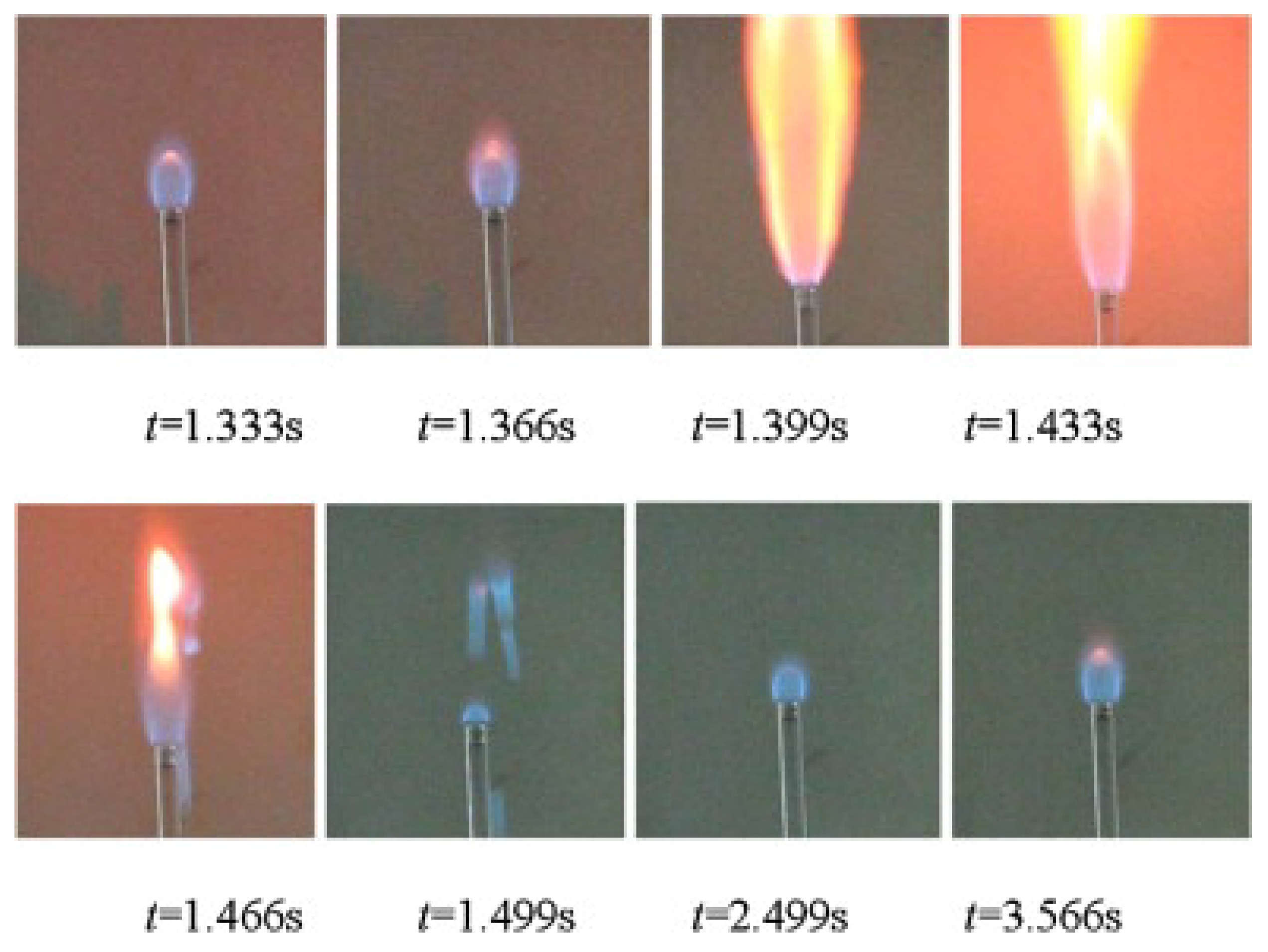
As the solid temperature continues to rise by receiving heat from a flame, the flame resumes propagation once the local solid temperature reaches the critical temperature. Flame oscillation in the pores, known as repetitive extinction and ignition, has also been observed. Chen et al. [72] conducted an experiment with mini tube nozzles using ethanol as fuel. The flames were initially steady and blue at low fuel flow rates but became unstable and oscillated with an increase in fuel flow rate. The flame suddenly turned bright yellow and rose high, resembling an exploding flow, which subsequently resulted in intense combustion and numerous small droplet flame balls. This enlarged flame disappeared within less than 0.1 s, and a small blue flame arose marking the beginning of a new cycle. Figure 56 depicts the periodic explosive flame formed.
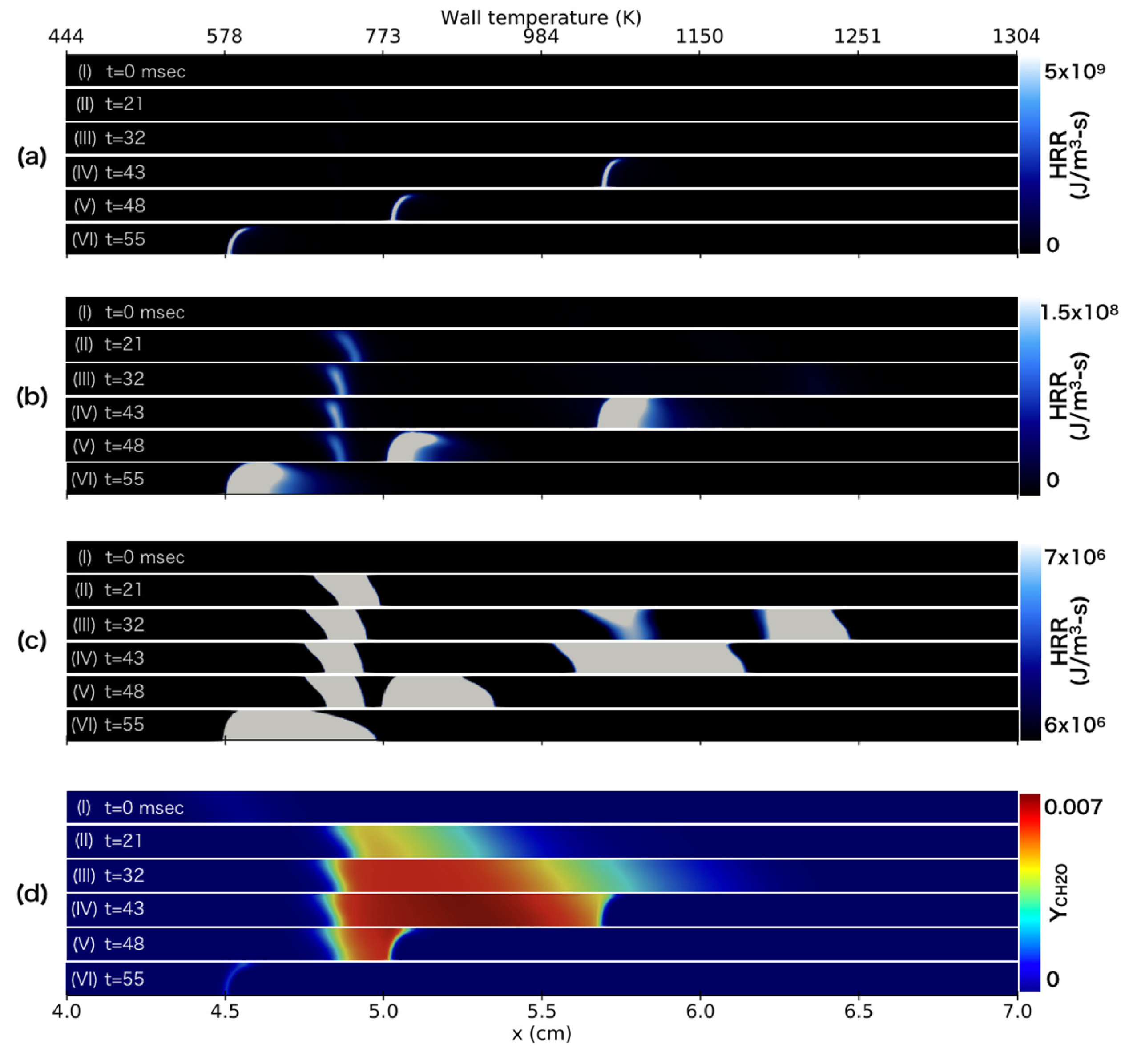
Akita et al. [73] numerically investigated the behaviour of a stoichiometric n-heptane/air mixture in a micro flow reactor with a controlled temperature profile. FREI behaviour of the n-heptane/air hot flame was observed along with three additional heat release rate peaks due to low-temperature oxidation. Figure 57 depicts the heat release rate contour along with CH 2 O mass fraction at specified time intervals.
Cool and blue flames were vividly identified. After ignition, the hot flame was observed to be merged with the cool flames in a specific order. The hot flame propagation speed increased and decreased, but was accelerated again downstream due to the effects of the stable cool flame. Akita et al. [74] also studied the effect of the diameter of quartz tubes and inlet flow velocity on the behaviour of flames in a micro flow reactor with a controlled temperature profile (MFR). Figure 58 shows the photographs of weak flames and FREI in an MFR with different diameters.
At a separation distance of 1 mm, cool flames and propagating reaction fronts (FREI) were observed to be spatially separated, while at 2 mm, they interacted. The brightness intensity of cool flames decreased with increasing inlet velocity above 10 cm/s. The reaction front propagation speed of FREI decreased at 1 mm due to heat loss and insignificant interaction with cool flames but increased temporarily in the downstream region of cool flames at 2 mm.

6. Summary and Outlook

In light of the growing apprehension over energy security and the pressing issue of climate change, exploring the potential liquid fuel in the field of miniature-scale combustion as a novel avenue for developing efficient energy conversion systems could be a promising research and development prospect. Presently available reviews are found to be extensively focused on micro combustors powered by gaseous fuels. In this review, we have focused on liquid fuel-based miniature-scale combustors. The implementation of liquid fuels in small-scale combustors has to overcome several hurdles to ultimately make a successful design. The atomization, evaporation, mixing, and burning of the liquid fuel within the short residence time have been some of the most challenging aspects. Different methods have been developed by researchers across the world to tackle these issues. In this work, we focused on bringing together all the aspects of liquid fuel combustion at a small scale which have been addressed as of now. Based on a thorough analysis of the existing strategies, we suggest the following recommendations for future work.
  • Flow-blurring atomizer is an ideal choice for ultra-low flow rate combustion systems as it can produce a fine spray without the need for high fuel injection pressure.
  • Injecting liquid fuel into porous media, which possesses unique characteristics such as a large specific surface area, excellent heat transport capability, and flow permeability, was found to be one of the most promising techniques for facilitating liquid fuel combustion in compact combustors.
  • The utilization of hydro-static pressure-driven pumping systems in miniature scale combustors is evidently a promising methodology for the development of standalone type power generators, because of the absence of electrical power-driven auxiliary components.
  • The technique of utilizing exhaust gas enthalpy to preheat and evaporate incoming liquid fuel holds great potential for the development of liquid-fuelled miniature combustors.
  • Investigations on electric power generation techniques from liquid-fueled miniature combustors are limited, and further investigation is necessary to advance the power generation methodology.

Author Contributions

Conceptualization, V.S. and S.S.; methodology, V.S.; formal analysis, S.S.; resources, V.S.; data curation, V.S. and S.S.; writing—original draft preparation, V.S. and S.S.; writing—review and editing, A.B.; supervision, R.K.V., S.M. and P.S.; funding acquisition, R.K.V. All authors have read and agreed to the published version of the manuscript.

Funding

The authors would like to thank Science and Engineering Research Board (SERB), Department of Science & Technology (DST), Govt of India for their partial funding through grant number CRG/2021/003079, under Core research grant scheme.

Data Availability Statement

Not applicable.

Conflicts of Interest

The authors declare no conflict of interest.

Nomenclature

M E M S Micro electromechanical systems
T E G Thermoelectric generator
T P V Thermophotovoltaic systems
F F Free flame
Z R O Zirconia foam
N I Nickel foam
I D Inner diameter
O D Outer diameter
F R E I Flame repetitive extinction and ignition
M F R Micro flow reactor

References

  1. Aravind, B.; Raghuram, G.K.; Kishore, V.R.; Kumar, S. Compact design of planar stepped micro combustor for portable thermoelectric power generation. Energy Convers. Manag. 2018, 156, 224–234. [Google Scholar] [CrossRef]
  2. Aravind, B.; Khandelwal, B.; Ramakrishna, P.; Kumar, S. Towards the development of a high power density, high efficiency, micro power generator. Appl. Energy 2020, 261, 114386. [Google Scholar] [CrossRef]
  3. Aravind, B.; Khandelwal, B.; Kumar, S. Recent Advancements in Microcombustion-Based Power Generators. Int. J. Energy Clean Environ. 2022, 23. [Google Scholar] [CrossRef]
  4. Aravind, B.; Hiranandani, K.; Kumar, S. Development of an ultra-high capacity hydrocarbon fuel based micro thermoelectric power generator. Energy 2020, 206, 118099. [Google Scholar] [CrossRef]
  5. Aravind, B.; Hiranandani, K.; Kumar, S. Experimental and Numerical Studies on Combustion-Based Small-Scale Power Generators. In Sustainable Development for Energy, Power, and Propulsion; Springer: Singapore, 2021; pp. 221–247. [Google Scholar]
  6. Behrens, D.A.; Lee, I.C.; Waits, C.M. Catalytic combustion of alcohols for microburner applications. J. Power Sources 2010, 195, 2008–2013. [Google Scholar] [CrossRef]
  7. Yang, X.; Yu, B.; Peng, X.; Zhou, H. Investigation of thermal performance and energy conversion in a novel planar micro-combustor with four-corner entrances for thermo-photovoltaic power generators. J. Power Sources 2021, 515, 230625. [Google Scholar] [CrossRef]
  8. Mazloomi, K.; Gomes, C. Hydrogen as an energy carrier: Prospects and challenges. Renew. Sustain. Energy Rev. 2012, 16, 3024–3033. [Google Scholar] [CrossRef]
  9. Kobayashi, H.; Hayakawa, A.; Somarathne, K.K.A.; Okafor, E.C. Science and technology of ammonia combustion. Proc. Combust. Inst. 2019, 37, 109–133. [Google Scholar] [CrossRef]
  10. Dunn-Rankin, D.; Leal, E.M.; Walther, D.C. Personal power systems. Prog. Energy Combust. Sci. 2005, 31, 422–465. [Google Scholar] [CrossRef]
  11. Kaisare, N.S.; Vlachos, D.G. A review on microcombustion: Fundamentals, devices and applications. Prog. Energy Combust. Sci. 2012, 38, 321–359. [Google Scholar] [CrossRef]
  12. Ju, Y.; Maruta, K. Microscale combustion: Technology development and fundamental research. Prog. Energy Combust. Sci. 2011, 37, 669–715. [Google Scholar] [CrossRef]
  13. Fernandez-Pello, A.C. Micropower generation using combustion: Issues and approaches. Proc. Combust. Inst. 2002, 29, 883–899. [Google Scholar] [CrossRef]
  14. Walther, D.C.; Ahn, J. Advances and challenges in the development of power-generation systems at small scales. Prog. Energy Combust. Sci. 2011, 37, 583–610. [Google Scholar] [CrossRef]
  15. Chou, S.; Yang, W.; Chua, K.; Li, J.; Zhang, K. Development of micro power generators—A review. Appl. Energy 2011, 88, 1–16. [Google Scholar] [CrossRef]
  16. Shirsat, V.; Gupta, A. A review of progress in heat recirculating meso-scale combustors. Appl. Energy 2011, 88, 4294–4309. [Google Scholar] [CrossRef]
  17. Nakamura, Y.; Gao, J.; Matsuoka, T. Progress in small-scale combustion. J. Therm. Sci. Technol. 2017, 12, JTST0001. [Google Scholar] [CrossRef]
  18. Wan, J.; Fan, A. Recent progress in flame stabilization technologies for combustion-based micro energy and power systems. Fuel 2021, 286, 119391. [Google Scholar] [CrossRef]
  19. Khan, M.A.; Gadgil, H.; Kumar, S. Influence of liquid properties on atomization characteristics of flow-blurring injector at ultra-low flow rates. Energy 2019, 171, 1–13. [Google Scholar] [CrossRef]
  20. Sadasivuni, V.; Agrawal, A.K. A novel meso-scale combustion system for operation with liquid fuels. Proc. Combust. Inst. 2009, 32, 3155–3162. [Google Scholar] [CrossRef]
  21. Gañán-Calvo, A.M. Enhanced liquid atomization: From flow-focusing to flow-blurring. Appl. Phys. Lett. 2005, 86, 214101. [Google Scholar] [CrossRef]
  22. Qavi, I.; Jiang, L. Optical characterization of near-field sprays for various alternative and conventional jet fuels using a flow-blurring injector. Flow Turbul. Combust. 2022, 108, 599–624. [Google Scholar] [CrossRef]
  23. Peck, J. Development of a Liquid-Fueled Micro-Combustor. Ph.D. Thesis, Massachusetts Institute of Technology, Cambridge, MA, USA, 2008. [Google Scholar]
  24. Sirignano, W.A.; Pham, T.K.; Dunn-Rankin, D. Miniature-scale liquid-fuel-film combustor. Proc. Combust. Inst. 2002, 29, 925–931. [Google Scholar] [CrossRef]
  25. Vijayan, V.; Gupta, A. Thermal performance of a meso-scale liquid-fuel combustor. Appl. Energy 2011, 88, 2335–2343. [Google Scholar] [CrossRef]
  26. Giovannoni, V.; Sharma, R.N.; Raine, R.R. Experimental investigation of a small-scale combustion chamber fuelled with vegetable oil. Combust. Sci. Technol. 2019, 192, 240–259. [Google Scholar] [CrossRef]
  27. Simmons, B.M.; Panchasara, H.V.; Agrawal, A.K. A comparison of air-blast and flow-blurring injectors using phase Doppler particle analyzer technique. In Proceedings of the Turbo Expo: Power for Land, Sea, and Air, Orlando, FL, USA, 8–12 June 2009; Volume 48838, pp. 981–992. [Google Scholar]
  28. Jiang, L.; Agrawal, A.K. Spray features in the near field of a flow-blurring injector investigated by high-speed visualization and time-resolved PIV. Exp. Fluids 2015, 56, 1–13. [Google Scholar] [CrossRef]
  29. Azevedo, C.G.; de Andrade, J.C.; de Souza Costa, F. Effects of nozzle exit geometry on spray characteristics of a blurry injector. At. Sprays 2013, 23, 193–209. [Google Scholar] [CrossRef]
  30. de Azevedo, C.G.; de Andrade, J.C.; de Souza Costa, F. Effects of injector tip design on the spray characteristics of soy methyl ester biodiesel in a blurry injector. Renew. Energy 2016, 85, 287–294. [Google Scholar] [CrossRef]
  31. de Azevedo, C.G.; de Andrade, J.C.; de Souza, F.C. Experimental valuation diagnostics of hydrous ethanol sprays formed by a blurry injector. J. Aerosp. Technol. Manag. 2013, 5, 197–204. [Google Scholar] [CrossRef]
  32. Pham, T.K.; Amade, N.S.; Dunn-Rankin, D.; Sirignano, W. Liquid film combustion in small cylindrical chambers. In Proceedings of the Fourth Joint Meeting of the US Sections of the Combustion Institute, Philadelphia, PA, USA, 20–23 March 2005. [Google Scholar]
  33. Pham, T.K.; Dunn-Rankin, D.; Sirignano, W.A. Flame structure in small-scale liquid film combustors. Proc. Combust. Inst. 2007, 31, 3269–3275. [Google Scholar] [CrossRef]
  34. Li, Y.H.; Chao, Y.C.; Amadé, N.S.; Dunn-Rankin, D. Progress in miniature liquid film combustors: Double chamber and central porous fuel inlet designs. Exp. Therm. Fluid Sci. 2008, 32, 1118–1131. [Google Scholar] [CrossRef]
  35. Jaworek, A.; Krupa, A. Classification of the modes of EHD spraying. J. Aerosol Sci. 1999, 30, 873–893. [Google Scholar] [CrossRef]
  36. Chen, X.; Li, J.; Feng, M.; Zhao, D.; Shi, B.; Wang, N. Flame stability and combustion characteristics of liquid fuel in a meso-scale burner with porous media. Fuel 2019, 251, 249–259. [Google Scholar] [CrossRef]
  37. Weclas, M. Potential of porous-media combustion technology as applied to internal combustion engines. J. Thermodyn. 2010, 2010, 789262. [Google Scholar] [CrossRef]
  38. Gharehghani, A.; Ghasemi, K.; Siavashi, M.; Mehranfar, S. Applications of porous materials in combustion systems: A comprehensive and state-of-the-art review. Fuel 2021, 304, 121411. [Google Scholar] [CrossRef]
  39. Mujeebu, M.A.; Abdullah, M.; Bakar, M.A.; Mohamad, A.; Abdullah, M. A review of investigations on liquid fuel combustion in porous inert media. Prog. Energy Combust. Sci. 2009, 35, 216–230. [Google Scholar] [CrossRef]
  40. Li, Y.H.; Chao, Y.C.; Dunn-Rankin, D. Combustion in a meso-scale liquid-fuel-film combustor with central-porous fuel inlet. Combust. Sci. Technol. 2008, 180, 1900–1919. [Google Scholar] [CrossRef]
  41. Li, J.; Huang, J.; Yan, M.; Zhao, D.; Zhao, J.; Wei, Z.; Wang, N. Experimental study of n-heptane/air combustion in meso-scale burners with porous media. Exp. Therm. Fluid Sci. 2014, 52, 47–58. [Google Scholar] [CrossRef]
  42. Chen, X.; Li, J.; Zhao, D.; Rashid, M.T.; Zhou, X.; Wang, N. Effects of porous media on partially premixed combustion and heat transfer in meso-scale burners fuelled with ethanol. Energy 2021, 224, 120191. [Google Scholar] [CrossRef]
  43. Majid, N.A.; Idris, A.C.; Faizal, H.M.; Rahman, M.R.A.; Hosseini, S.E. Characteristics of liquid fuel combustion in a novel miniature vortex combustor. J. Therm. Anal. Calorim. 2020, 140, 1569–1578. [Google Scholar] [CrossRef]
  44. Shi, B.; Cao, Q.; Xie, D.; Peng, W.; Wang, N. A novel combustion system for liquid fuel evaporating and burning. Proc. Combust. Inst. 2019, 37, 4329–4336. [Google Scholar] [CrossRef]
  45. Shimokuri, D.; Taomoto, Y.; Matsumoto, R. Development of a powerful miniature power system with a meso-scale vortex combustor. Proc. Combust. Inst. 2017, 36, 4253–4260. [Google Scholar] [CrossRef]
  46. Khan, M.A.; Kumar, S. Prototype development of a new self-aspirating liquid-fueled microcombustor. Combust. Sci. Technol. 2022, 1–21. [Google Scholar] [CrossRef]
  47. Kyritsis, D.C.; Roychoudhury, S.; McEnally, C.S.; Pfefferle, L.D.; Gomez, A. Mesoscale combustion: A first step towards liquid fueled batteries. Exp. Therm. Fluid Sci. 2004, 28, 763–770. [Google Scholar] [CrossRef]
  48. Yuliati, L.; Seo, T.; Mikami, M. Liquid-fuel combustion in a narrow tube using an electrospray technique. Combust. Flame 2012, 159, 462–464. [Google Scholar] [CrossRef]
  49. Gan, Y.; Luo, Z.; Cheng, Y.; Xu, J. The electro-spraying characteristics of ethanol for application in a small-scale combustor under combined electric field. Appl. Therm. Eng. 2015, 87, 595–604. [Google Scholar] [CrossRef]
  50. Gan, Y.; Tong, Y.; Ju, Y.; Zhang, X.; Li, H.; Chen, X. Experimental study on electro-spraying and combustion characteristics in meso-scale combustors. Energy Convers. Manag. 2017, 131, 10–17. [Google Scholar] [CrossRef]
  51. Gan, Y.; Tong, Y.; Jiang, Z.; Chen, X.; Li, H.; Jiang, X. Electro-spraying and catalytic combustion characteristics of ethanol in meso-scale combustors with steel and platinum meshes. Energy Convers. Manag. 2018, 164, 410–416. [Google Scholar] [CrossRef]
  52. Gan, Y.; Chen, X.; Tong, Y.; Zhang, X.; Zhang, Y. Thermal performance of a meso-scale combustor with electrospray technique using liquid ethanol as fuel. Appl. Therm. Eng. 2018, 128, 274–281. [Google Scholar] [CrossRef]
  53. Jiang, Z.; Gan, Y.; Ju, Y.; Liang, J.; Zhou, Y. Experimental study on the electrospray and combustion characteristics of biodiesel-ethanol blends in a meso-scale combustor. Energy 2019, 179, 843–849. [Google Scholar] [CrossRef]
  54. Stanchi, S.; Dunn-Rankin, D.; Sirignano, W. Combustor Miniaturization with Liquid-Fuel Filming. In Proceedings of the 41st Aerospace Sciences Meeting and Exhibit, Reno, NV, USA, 6–9 January 2003; p. 1163. [Google Scholar]
  55. Li, Y.H.; Chao, Y.C.; Dunn-Rankin, D. Combustion in Small-Scale Central-Porous-Media Liquid Film Combustors. In Proceedings of the 21st International Colloquium on Dynamics of Explosions and Reactive Systems, Poitiers, France, 23–27 July 2007; pp. 23–27. [Google Scholar]
  56. Giani, C.; Dunn-Rankin, D. Miniature fuel film combustor: Swirl vane design and combustor characterization. Combust. Sci. Technol. 2013, 185, 1464–1481. [Google Scholar] [CrossRef]
  57. da Silva, A.P.; Sauer, V.M.; Dunn-Rankin, D. Experimental evaluation of a miniature liquid film combustor with secondary air injection. In Proceedings of the Fall 2015 Meeting of the Western States Section of the Combustion Institute, Provo, UT, USA, 5–6 October 2015; pp. 1–9. [Google Scholar]
  58. Sauer, V.M.; Dunn-Rankin, D. Liquid fuel nonpremixed swirl-type tubular flame burner. Combust. Sci. Technol. 2018, 195, 1–12. [Google Scholar] [CrossRef]
  59. Li, J.; Huang, J.; Zhao, D.; Zhao, J.; Yan, M.; Wang, N. Diffusion combustion of liquid heptane in a small tube with and without heat recirculating. Combust. Sci. Technol. 2012, 184, 1591–1607. [Google Scholar] [CrossRef]
  60. Li, J.; Huang, J.; Chen, X.; Zhao, D.; Shi, B.; Wei, Z.; Wang, N. Effects of heat recirculation on combustion characteristics of n-heptane in micro combustors. Appl. Therm. Eng. 2016, 109, 697–708. [Google Scholar] [CrossRef]
  61. Li, J.; Huang, J.; Chen, X.; Yan, M.; Zhao, D.; Wei, Z.; Wang, N. Experimental study on flame stability and thermal performance of an n-heptane-fueled microscale combustor. Combust. Sci. Technol. 2017, 189, 1198–1215. [Google Scholar] [CrossRef]
  62. Chen, X.; Li, J.; Feng, M.; Wang, N. Effects of external heating on flame stability in a micro porous combustor fuelled with heptane. Combust. Sci. Technol. 2019, 191, 311–324. [Google Scholar] [CrossRef]
  63. Bharadwaz, N.A.; Jain, N.; Arghode, V.K. Development of a standalone, liquid fuelled miniature power generation system. J. Energy Resour. Technol. 2020, 142, 042004. [Google Scholar] [CrossRef]
  64. Li, Y.H.; Lien, Y.S.; Chao, Y.C.; Dunn-Rankin, D. Performance of a mesoscale liquid fuel-film combustion-driven TPV power system. Prog. Photovoltaics Res. Appl. 2009, 17, 327–336. [Google Scholar] [CrossRef]
  65. Li, Y.H.; Li, H.Y.; Dunn-Rankin, D.; Chao, Y.C. Enhancing thermal, electrical efficiencies of a miniature combustion-driven thermophotovoltaic system. Prog. Photovoltaics Res. Appl. 2009, 17, 502–512. [Google Scholar] [CrossRef]
  66. Jain, N.; Arghode, V. Development of a Standalone, Liquid Fuelled Miniature Power Generation System. In Proceedings of the ASME Power Conference. American Society of Mechanical Engineers, Charlotte, NC, USA, 26–30 June 2017; Volume 57601, p. V001T04A028. [Google Scholar]
  67. Singh, S.; Veetil, J.E.; Kumbhakarna, N.; Velamati, R.K.; Kumar, S. Flame dynamics of premixed CH4/H2/air flames in a microchannel with a wall temperature gradient. Combust. Theory Model. 2022, 26, 989–1013. [Google Scholar] [CrossRef]
  68. Nair, A.; Kishore, V.R.; Kumar, S. Dynamics of premixed hydrogen-air flames in microchannels with a wall temperature gradient. Combust. Sci. Technol. 2015, 187, 1620–1637. [Google Scholar] [CrossRef]
  69. Veetil, J.E.; Kumbhakarna, N.; Singh, S.; Velamati, R.K.; Kumar, S. Effect of hydrogen addition on the dynamics of premixed C1–C4 alkane-air flames in a microchannel with a wall temperature gradient. Int. J. Hydrogen Energy 2022, 47, 30660–30670. [Google Scholar] [CrossRef]
  70. Kishore, V.R.; Minaev, S.; Akram, M.; Kumar, S. Dynamics of premixed methane/air mixtures in a heated microchannel with different wall temperature gradients. RSC Adv. 2017, 7, 2066–2073. [Google Scholar] [CrossRef]
  71. Chen, X.; Li, J.; Zhao, D.; Song, A.; Zhou, X.; Wang, N. Experimental investigation on propagation characteristics of n-heptane/air combustion wave in foamed porous media. Fuel 2021, 306, 121742. [Google Scholar] [CrossRef]
  72. Chen, J.; Peng, X.; Yang, Z.; Cheng, J. Characteristics of liquid ethanol diffusion flames from mini tube nozzles. Combust. Flame 2009, 156, 460–466. [Google Scholar] [CrossRef]
  73. Akita, K.; Morii, Y.; Nakamura, H.; Tezuka, T.; Maruta, K. 2D computations of FREI with cool flames for n-heptane/air mixture. Proc. Combust. Inst. 2021, 38, 2247–2255. [Google Scholar] [CrossRef]
  74. Akita, K.; Morii, Y.; Murakami, Y.; Nakamura, H.; Tezuka, T.; Maruta, K. Dynamics of FREI with/without cool flame interaction. Proc. Combust. Inst. 2022. [Google Scholar] [CrossRef]
Figure 1. Growing interest towards the development of small-scale combustion-based power generation technology. The study was carried out in scopus using “micro combustor” or “meso combustor” or “miniature combustor” and “power generation” as the keyword.
Energies 16 04035 g001
Figure 2. Volumetric Versus gravimetric energy density of different hydrocarbon fuels [8,9].
Energies 16 04035 g002
Figure 3. Increasing interest towards the development of small-scale liquid fuel combustors. The study was carried out in scopus using “liquid fuel” or “electrospray” or “liquid fuel film” or “spray” and “micro combustor” as the keyword.
Energies 16 04035 g003
Figure 4. Power requirements for different gadgets [10,11].
Energies 16 04035 g004
Figure 5. Concept of flow burring injector [22].
Energies 16 04035 g005
Figure 6. Concept of fuel film injection [33].
Energies 16 04035 g006
Figure 7. Concept of double chamber fuel film combustor [34].
Energies 16 04035 g007
Figure 8. Mechanism of evaporation and combustion in a double chamber fuel film combustor [34].
Energies 16 04035 g008
Figure 9. Concept of fuel film combustor with porous insert [34].
Energies 16 04035 g009
Figure 10. Mechanism of evaporation and combustion in a fuel film combustor with porous insert [34].
Energies 16 04035 g010
Figure 11. Mechanism of miniature vortex combustor [43].
Energies 16 04035 g011
Figure 12. Self aspirating pump free liquid fuel micro-combustor [46].
Energies 16 04035 g012
Figure 13. Schematic representation presents an overview of how the burner functions [47].
Energies 16 04035 g013
Figure 14. Variation of CO mole fraction (■) and the ratio of CO 2 and CO (∘) on molar basis w.r.t equivalence ratio [47].
Energies 16 04035 g014
Figure 15. Flame images for different conditions of flow rate using an electrospray [49].
Energies 16 04035 g015
Figure 16. Schematic of mesoscale combustor (a) Type A and (b) Type B design [50].
Energies 16 04035 g016
Figure 17. Ethanol flame structure in the two mesoscale combustor designs [50].
Energies 16 04035 g017
Figure 18. Flame structure infrared image of wall for different equivalence ratios [52].
Energies 16 04035 g018
Figure 19. Schematic of micro-combustor, images of electrospray and flame inside the narrow tube and the axial droplet velocity distribution [48].
Energies 16 04035 g019
Figure 20. Flame structure of biodiesel ethanol blends in the mesoscale combustor [53].
Energies 16 04035 g020
Figure 21. Flame stabilized over the porous medium [20].
Energies 16 04035 g021
Figure 22. Methane gas flame with spiral swirler [24].
Energies 16 04035 g022
Figure 23. Methane plus liquid methanol fuel film flame [24].
Energies 16 04035 g023
Figure 24. Heptane fuel film combustion at increasing air flow rates (af), Image (g) represents a stoichiometric condition [24].
Energies 16 04035 g024
Figure 25. Liquid fuel film combustor with swirl vanes [54].
Energies 16 04035 g025
Figure 26. Photograph of liquid fuel film miniature combusting using n-heptane as the fuel [33].
Energies 16 04035 g026
Figure 27. Depicts the temperature measurements taken above the chamber rim [33].
Energies 16 04035 g027
Figure 28. Two separate flame structures of a rim flame and a central triple flame [33].
Energies 16 04035 g028
Figure 29. Depicts the presence of fuel richer regions near the wall and leaner regions in the centre [33].
Energies 16 04035 g029
Figure 30. (a) Schematic representation (b) real image of the fuel film combustor with porous insert [40].
Energies 16 04035 g030
Figure 31. Flame anchoring and flame structure for different porous materials [40].
Energies 16 04035 g031
Figure 32. Flame anchor position with different porous materials [40].
Energies 16 04035 g032
Figure 33. Radical concentration of (b) C 2 ∗ (c) CH∗ (d) OH∗ along with the corresponding (a) flame image for a fuel film combustor with stainless steel porous cap [40].
Energies 16 04035 g033
Figure 34. Radical concentration of (b) C 2 ∗ (c) CH∗ (d) OH∗ along with the corresponding (a) flame image for a fuel film combustor with bronze porous cap [40].
Energies 16 04035 g034
Figure 35. (A) Thermocouple locations (B) Methanol flame structure (C) Temperature profile across the combustor [34].
Energies 16 04035 g035
Figure 36. Heptane flame structure in double wall fuel film combustor [34].
Energies 16 04035 g036
Figure 37. Temperature profile outside the inner wall of double wall fuel film combustor at different air flow rates (A) at hole #3 (B) at hole #5 [34].
Energies 16 04035 g037
Figure 38. Central porous fuel insert combustor configuration [34].
Energies 16 04035 g038
Figure 39. Flame structure of n-heptane flame in a central porous fuel insert combustor configuration [34].
Energies 16 04035 g039
Figure 40. Effect of (A) porous material and (B) pore size used in the central porous insert fuel film combustor [34].
Energies 16 04035 g040
Figure 41. Prototype design of the swirl vane added fuel film combustor [56].
Energies 16 04035 g041
Figure 42. Stable flame for an aluminium combustor with different swirl designs [56].
Energies 16 04035 g042
Figure 43. Comparison of wall temperature profile for the combustor with and without secondary injection [57].
Energies 16 04035 g043
Figure 44. Schematic diagram of the liquid-fuelled porous wall combustor [58].
Energies 16 04035 g044
Figure 45. Work limit map of liquid-fuelled porous wall combustor [58].
Energies 16 04035 g045
Figure 46. Shcematic of the experimental setup [36].
Energies 16 04035 g046
Figure 47. Flame structure of ethanol, n-heptane and dodecane flame [36].
Energies 16 04035 g047
Figure 48. Flame structure in burner with different porous materials (a) FF burner (b) NI burner (c) ZRO burner [42].
Energies 16 04035 g048
Figure 49. Schematic of the experimental setup [59].
Energies 16 04035 g049
Figure 50. Schematic of the experimental setup [41].
Energies 16 04035 g050
Figure 51. Schematic of micro combustor with different thermal insulations [60].
Energies 16 04035 g051
Figure 52. Flame structure in the miniature vortex combustor at different equivalence ratios [43].
Energies 16 04035 g052
Figure 53. Ethanol flame structure in the self aspirating combustor [46].
Energies 16 04035 g053
Figure 54. (a) Shows the schematic (b) image of the experimental setup and (c) shows the photograph of the TPV-based power system [64].
Energies 16 04035 g054
Figure 55. Process of flame pulsation in a porous media combustor [71].
Energies 16 04035 g055
Figure 56. Periodic explosive flames [72].
Energies 16 04035 g056
Figure 57. (ac) The heat release rate contour along with (d) CH 2 O mass fraction at specified time intervals [73].
Energies 16 04035 g057
Figure 58. Photographs of weak flames and FREI in an MFR with different diameters [74].
Energies 16 04035 g058
Table 1. Summary of different definitions for micro/meso scale combustion.
Reference Length ScaleCombustion RegimeLength Scale
Physical lengthMesoscale1–10 mm
Microscale1–1000 μ m
Quenching diameterMesoscale∼Quenching diameter
MicroscaleQuenching diameter ∼ mean free path
Device scaleMicroscaleSmaller than conventional device size
Table 3. Summary of a porous medium in the liquid fuel micro/meso scale combustor.
Previous WorksLiquid FuelPorous Medium UsedPorosity
Heng Li et al. [40]n-HeptaneSintered powder35.6
Agarwal et al. [20]KeroseneSilicon carbide coated carbon foam85
Junwei Li et al. [41]n-HeptaneGraphite fiber87
Junwei Li et al. [36]n-HeptaneNickel foam95
Chen et al. [42]EthanolNickel foam, Zirconia foam95, 96, 80.7
Table 4. Summary of Liquid Fuel Micro Combustor Features Reported in Literature.
Previous WorksLiquid FuelThermal Capacity (W)Combustor Size (cc)CO (ppm)NOx (ppm)
Kyritsis et al. [47]JP811943.41000–5000-
Agarwal et al. [20]Kerosene180–4606.8220–250240–310
Li et al. [64]n-Heptane460–5804.3100–10,00020–60
Jiang et al. [53]Biodiesel-ethanol blends-11.33900–8500-
Chen et al. [36]n-heptane45–768.4620–20040–75
Giovannoni et al. [26]Vegetable Oil194–55458.91000–500010–90
Chen et al. [42]Ethanol-8.4622–13,6945–55
Azad et al. [46]Ethanol6–1718.3224–423-
Disclaimer/Publisher’s Note: The statements, opinions and data contained in all publications are solely those of the individual author(s) and contributor(s) and not of MDPI and/or the editor(s). MDPI and/or the editor(s) disclaim responsibility for any injury to people or property resulting from any ideas, methods, instructions or products referred to in the content.