

Heat Transfer Augmentation Using Duplex and Triplex Tube Phase Change Material (PCM) Heat Exchanger Configurations


Abstract
:
1. Introduction
2. Numerical Model
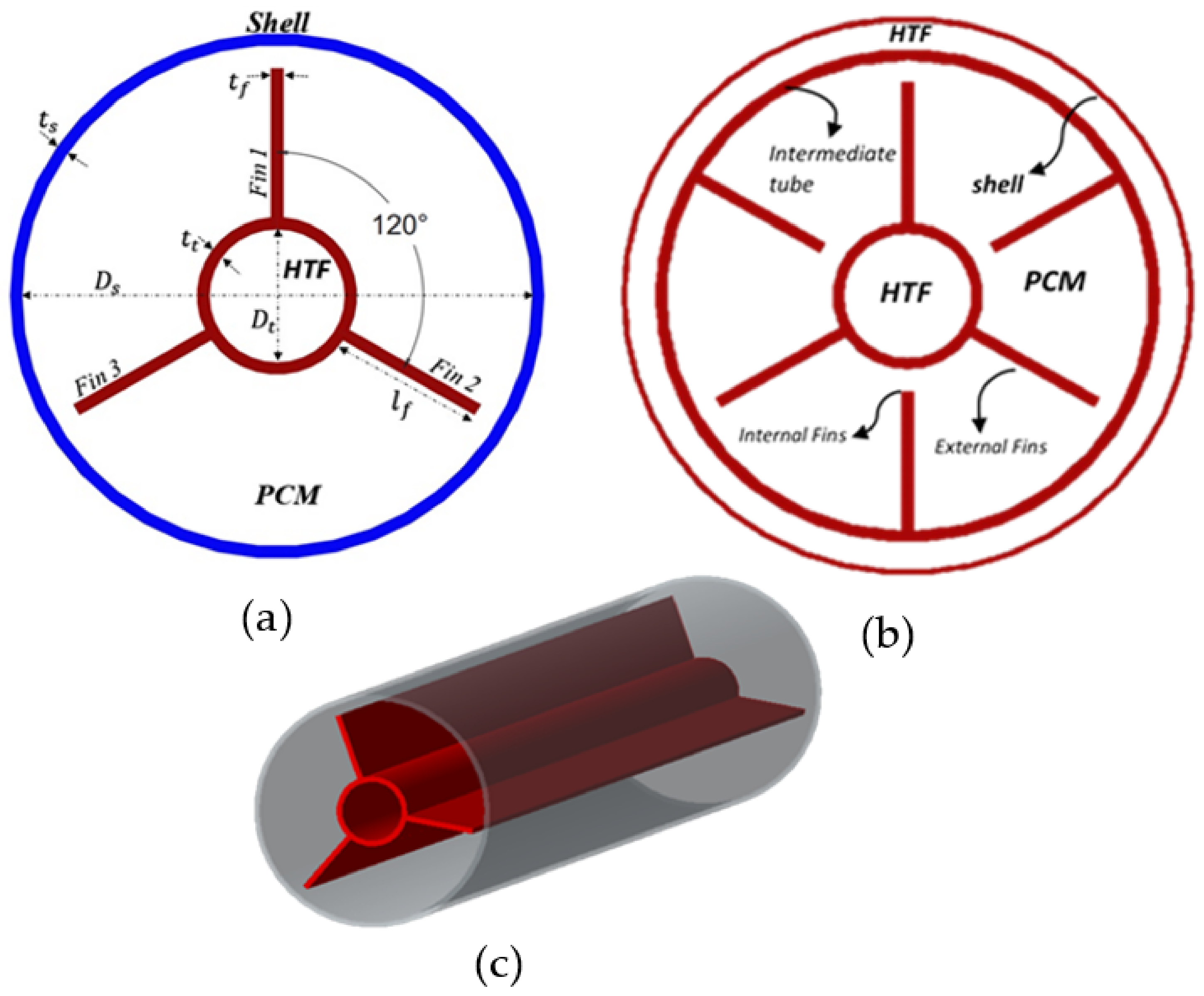
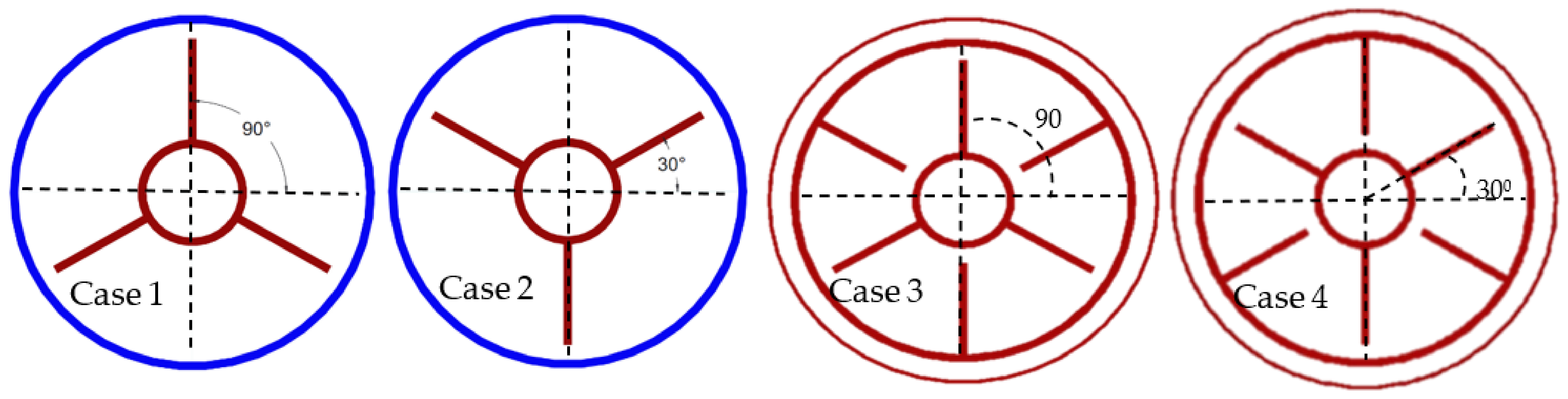
2.1. Computational Domain
2.2. Thermophysical Properties
2.3. Governing Equations
- (a)
- PCM = totally solid,
- (b)
- PCM = liquid and solid,
- (c)
- PCM = totally liquid.
2.4. Solver Settings
2.5. Initial and Boundary Conditions
3. Verification and Validation of the Model
3.1. Verification
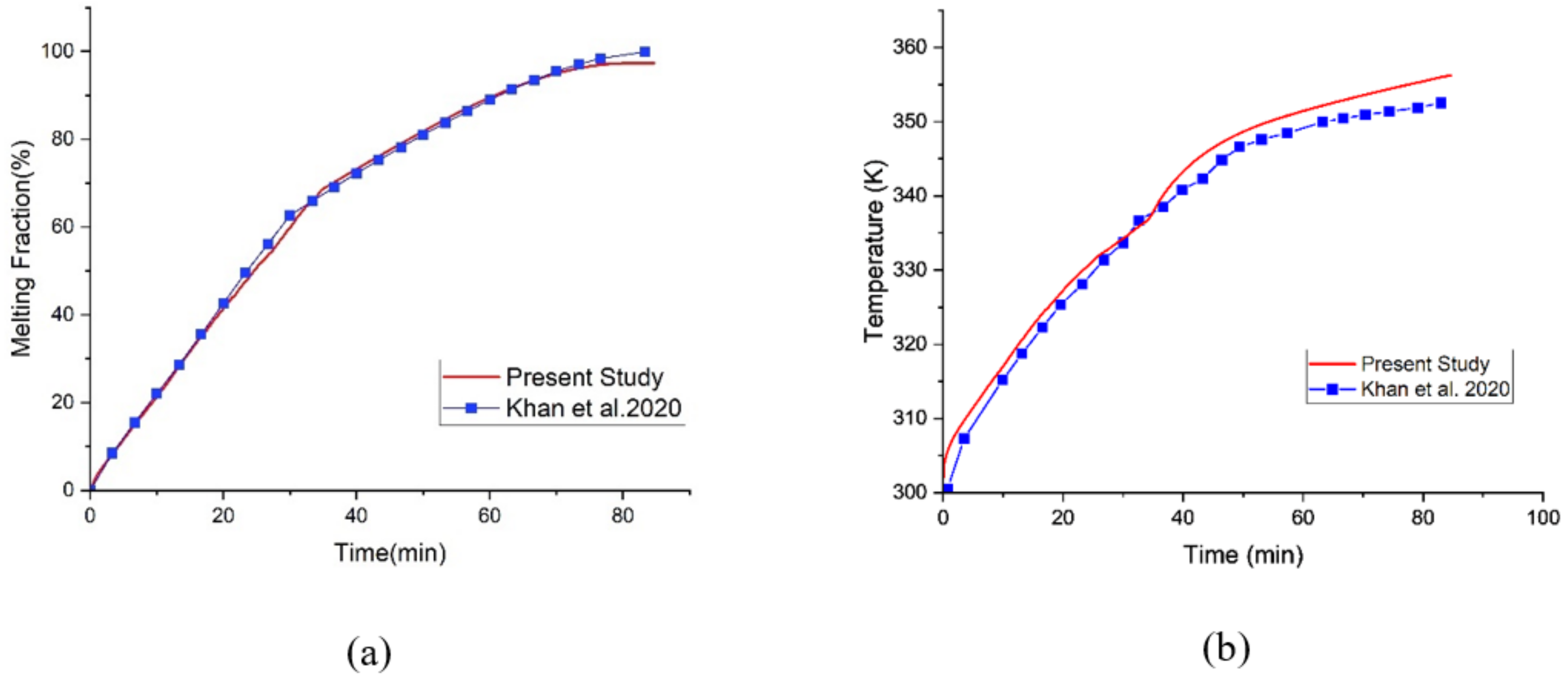
3.2. Validation
4. Results and Discussion
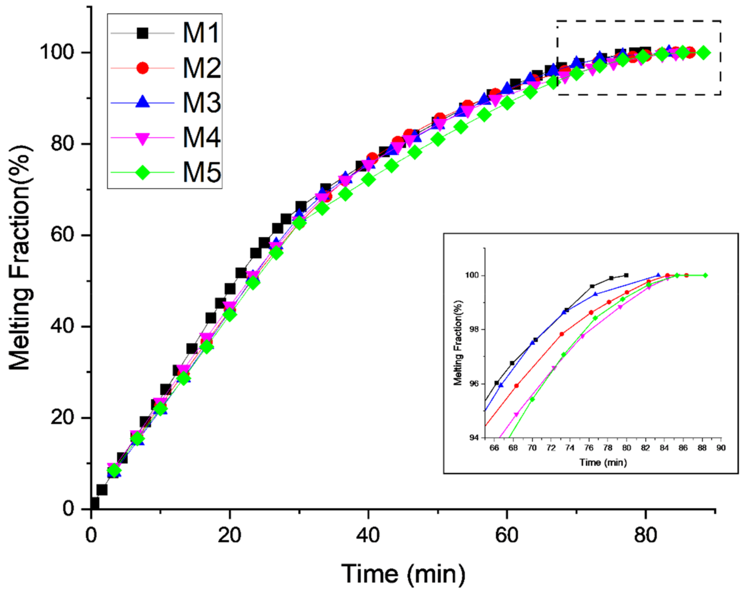
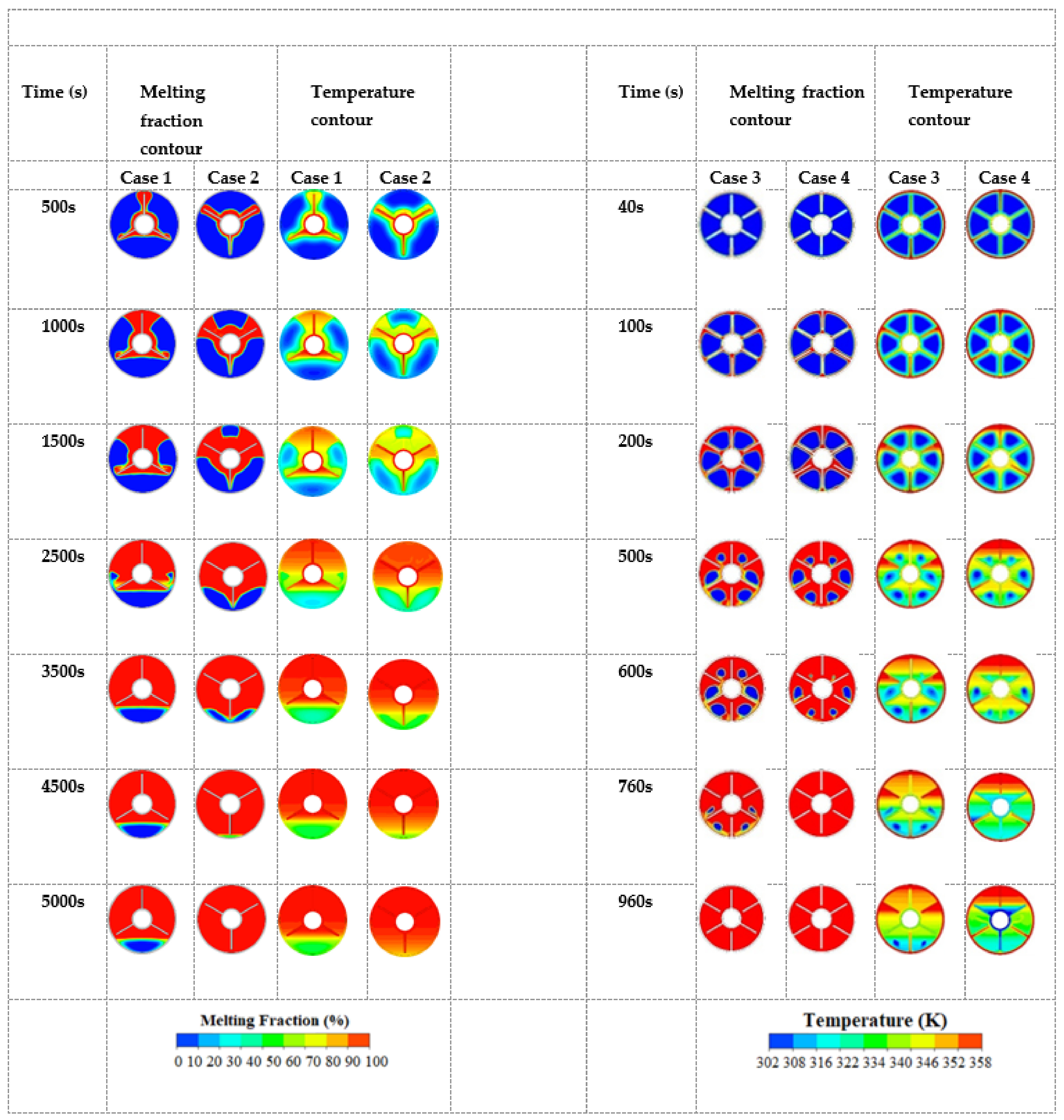
4.1. Melting Fraction and Temperature Profile
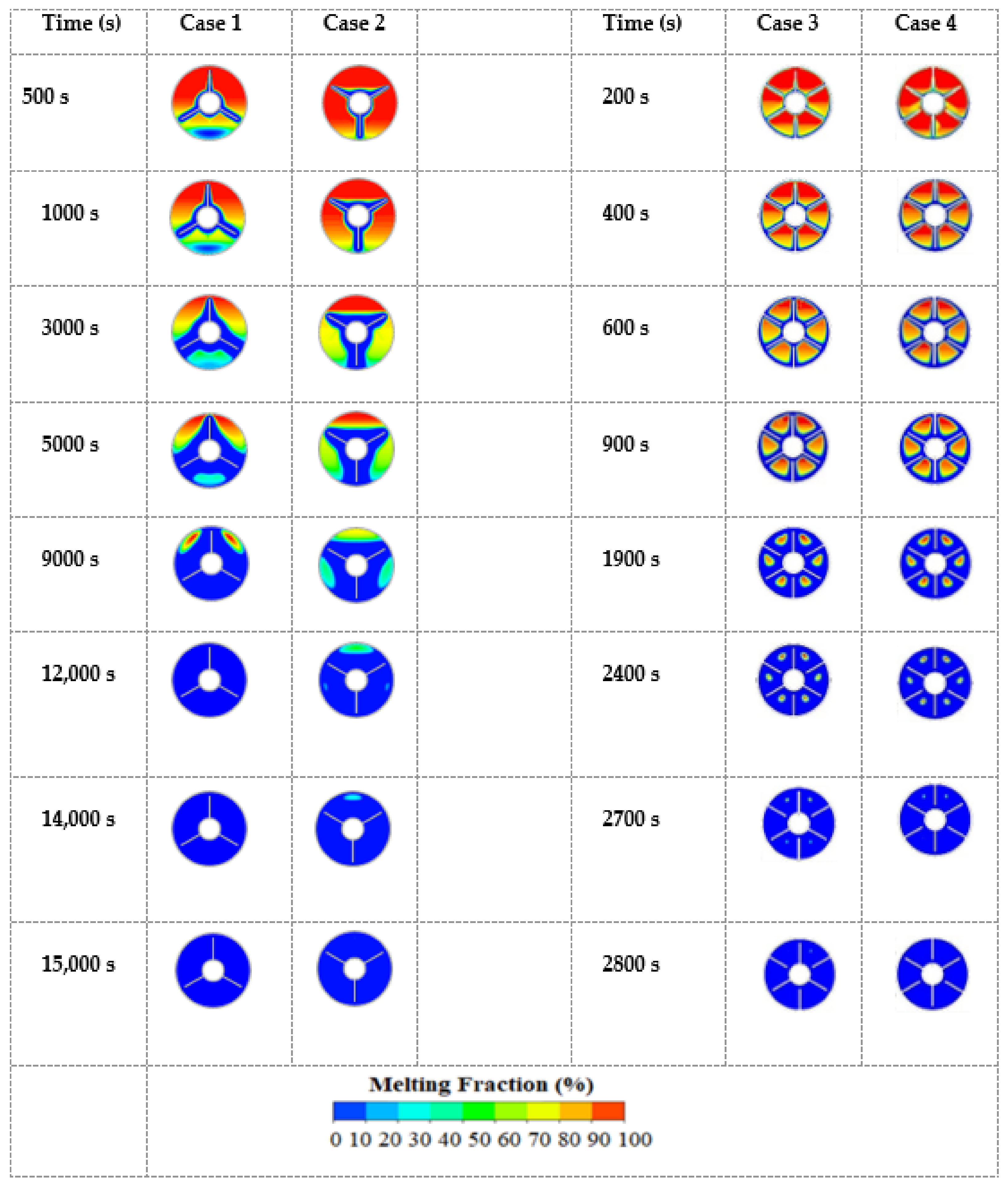
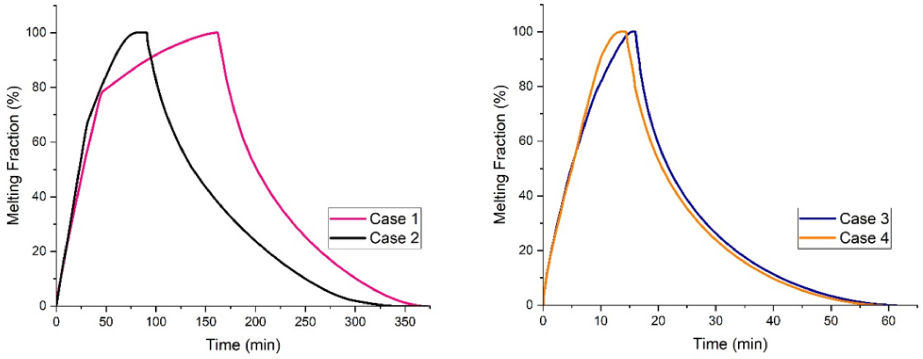
4.2. Comparison between Melting and Solidification
4.3. Effect of Tube Materials
4.4. Effect of Fin Length on Melting
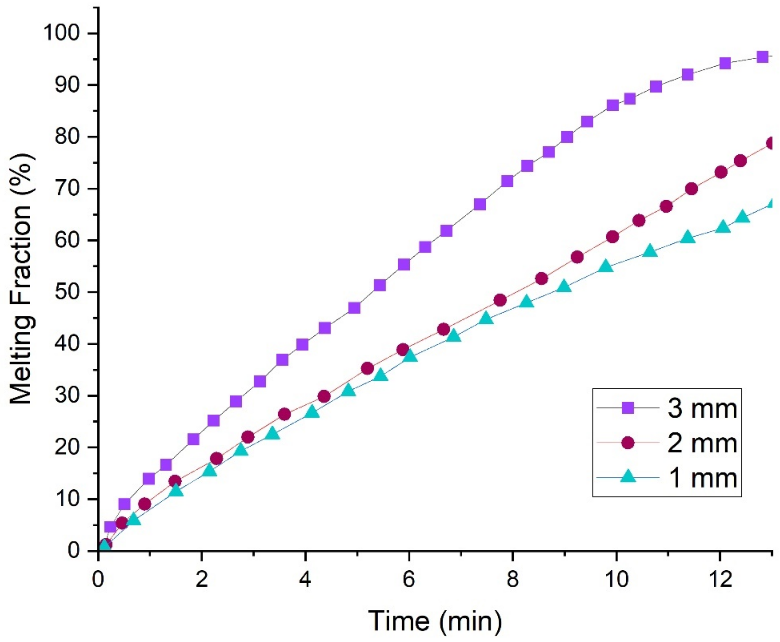
4.5. Effect of Fin Thickness on Melting
5. Conclusions
Author Contributions
Funding
Conflicts of Interest
Abbreviations and Nomenclature
| LTESU | Latent thermal energy storage unit |
| PCM | Phase change material |
| HTF | Heat transfer fluid |
| DTHX | Duplex-ube heat exchanger |
| TTHX | Triplex tube heat exchanger |
| υ | Orientation angle (deg) |
| Dt | Tube diameter (mm) |
| Ds | Shell diameter (mm) |
| tt | Tube thickness (mm) |
| lf | Fin length (mm) |
| tf | Fin thickness (mm) |
| C mushy | Mushy zone constant |
| u | Velocity (m/s) |
| Dynamic viscosity (kgm−1s−1) | |
| g | Gravity (m/s2) |
| Source term | |
| Density (kgm−3) | |
| l | Density of PCM, liquid (kgm−3) |
| s | Density of PCM, solid (kgm−3) |
| Thermal expansion coefficient (K−1) | |
| T | Temperature (K) |
| k | Thermal conductivity (Wm−1 K −1) |
| h | Enthalpy (Jkg−1) |
| Cp | Specific heat (Jkg−1K−1) |
| Tr | Reference temperature (K) |
| Latent heat of fusion (kJkg−1) | |
| Source term for momentum | |
| Melting fraction (%) | |
| t | Time (min, second) |
| TPCM | PCM temperature (K) |
| THTF | Heat transfer fluid temperature (K) |
| υ | Kinematic viscosity (m2 s−1) |
| f | Fins |
| c | Coefficient |
| Latent heat of fusion (kJkg−1) | |
| hc | Heat transfer coefficient (Wm−2K−1) |
| R | Reference |
| ε | Small number |
| ui | Velocity component (mms−1) |
| TS | Solidus temperature of PCM (K) |
| TL | Liquidus temperature of PCM (K) |
References
- Liu, M.; Saman, W.; Bruno, F. Review on storage materials and thermal performance enhancement techniques for high temperature phase change thermal storage systems. Renew. Sustain. Energy Rev. 2012, 16, 2118–2132. [Google Scholar] [CrossRef]
- Zhang, N.; Yuan, Y.; Cao, X.; Du, Y.; Zhang, Z.; Gui, Y. Latent heat thermal energy storage systems with solid–liquid phase change materials: A review. Adv. Eng. Mater. 2018, 20, 1700753. [Google Scholar] [CrossRef]
- Saidur, R. Energy consumption, energy savings, and emission analysis in Malaysian office buildings. Energy Policy 2009, 37, 4104–4113. [Google Scholar] [CrossRef]
- Pokhrel, R.; González, J.E.; Hight, T.; Adalsteinsson, T. Analysis and design of a paraffin/graphite composite PCM integrated in a thermal storage unit. J. Sol. Energy Eng. Trans. ASME 2010, 132, 041006. [Google Scholar] [CrossRef]
- Khan, L.A.; Khan, M.M. Role of orientation of fins in performance enhancement of a latent thermal energy storage unit. Appl. Therm. Eng. 2020, 175, 115408. [Google Scholar] [CrossRef]
- Motahar, S.; Alemrajabi, A.A.; Khodabandeh, R. Experimental study on solidification process of a phase change material containing TiO2 nanoparticles for thermal energy storage. Energy Convers. Manag. 2017, 138, 162–170. [Google Scholar] [CrossRef]
- Darzi, A.A.R.; Jourabian, M.; Farhadi, M. Melting and solidification of PCM enhanced by radial conductive fins and nanoparticles in cylindrical annulus. Energy Convers. Manag. 2016, 118, 253–263. [Google Scholar] [CrossRef]
- Mahdi, J.M.; Nsofor, E.C. Solidification enhancement in a triplex-tube latent heat energy storage system using nanoparticles-metal foam combination. Energy 2017, 126, 501–512. [Google Scholar] [CrossRef]
- Tay, N.H.S.; Liu, M.; Belusko, M.; Bruno, F. Review on transportable phase change material in thermal energy storage systems. Renew. Sustain. Energy Rev. 2017, 75, 264–277. [Google Scholar] [CrossRef]
- Tay, N.H.S.; Belusko, M.; Castell, A.; Cabeza, L.F.; Bruno, F. An effectiveness-NTU technique for characterising a finned tubes PCM system using a CFD model. Appl. Energy 2014, 131, 377–385. [Google Scholar] [CrossRef]
- Al-Abidi, A.A.; Mat, S.; Sopian, K.; Sulaiman, M.Y.; Mohammad, A.T. Numerical study of PCM solidification in a triplex tube heat exchanger with internal and external fins. Int. J. Heat Mass Transf. 2013, 61, 684–695. [Google Scholar] [CrossRef]
- Al-Abidi, A.A.; Mat, S.; Sopian, K.; Sulaiman, M.Y.; Mohammad, A.T. Experimental study of melting and solidification of PCM in a triplex tube heat exchanger with fins. Energy Build. 2014, 68, 33–41. [Google Scholar] [CrossRef]
- Zhao, D.; Tan, G. Numerical analysis of a shell-and-tube latent heat storage unit with fins for air-conditioning application. Appl. Energy 2015, 138, 381–392. [Google Scholar] [CrossRef]
- Erek, A.; İlken, Z.; Acar, M.A. Experimental and numerical investigation of thermal energy storage with a finned tube. Int. J. Energy Res. 2005, 29, 283–301. [Google Scholar] [CrossRef]
- Nie, C.; Deng, S.; Liu, J. Numerical investigation of PCM in a thermal energy storage unit with fins: Consecutive charging and discharging. J. Energy Storage 2020, 29, 101319. [Google Scholar] [CrossRef]
- Yu, C.; Wu, S.; Huang, Y.; Yao, F.; Liu, X. Charging performance optimization of a latent heat storage unit with fractal tree-like fins. J. Energy Storage 2020, 30, 101498. [Google Scholar] [CrossRef]
- Nóbrega, C.R.E.S.; Ismail, K.A.R.; Lino, F.A.M. Solidification around axial finned tube submersed in PCM: Modeling and experiments. J. Energy Storage 2020, 29, 101438. [Google Scholar] [CrossRef]
- Yu, C.; Zhang, X.; Chen, X.; Zhang, C.; Chen, Y. Melting performance enhancement of a latent heat storage unit using gradient fins. Int. J. Heat Mass Transf. 2020, 150, 119330. [Google Scholar] [CrossRef]
- Chen, G.; Sun, G.; Jiang, D.; Su, Y. Experimental and numerical investigation of the latent heat thermal storage unit with PCM packing at the inner side of a tube. Int. J. Heat Mass Transf. 2020, 152, 119480. [Google Scholar] [CrossRef]
- Mehta, D.; Vaghela, B.; Rathod, M.K.; Banerjee, J. Thermal performance augmentation in latent heat storage unit using spiral fin: An experimental analysis. J. Energy Storage 2020, 31, 101776. [Google Scholar] [CrossRef]
- Wu, S.; Huang, Y.; Zhang, C.; Chen, Y. Role of tree-shaped fins in charging performance of a latent heat storage unit. Int. J. Energy Res. 2020, 44, 4800–4811. [Google Scholar] [CrossRef]
- Kalapala, L.; Devanuri, J.K. Energy and exergy analyses of latent heat storage unit positioned at different orientations–An experimental study. Energy 2020, 194, 116924. [Google Scholar] [CrossRef]
- Mehta, D.; Solanki, K.; Rathod, M.; Banerjee, J. Thermal performance of shell and tube latent heat storage unit: Comparative assessment of horizontal and vertical orientation. J. Energy Storage 2019, 23, 344–362. [Google Scholar] [CrossRef]
- Lamrani, B.; Kuznik, F.; Draoui, A. Thermal performance of a coupled solar parabolic trough collector latent heat storage unit for solar water heating in large buildings. Renew. Energy 2020, 162, 411–426. [Google Scholar] [CrossRef]
- Rezaei, E.; Barbato, M.; Ortona, A.; Haussener, S. Design and optimization of a high-temperature latent heat storage unit. Appl. Energy 2020, 261, 114330. [Google Scholar] [CrossRef]
- Zhang, C.; Li, J.; Chen, Y. Improving the energy discharging performance of a latent heat storage (LHS) unit using fractal-tree-shaped fins. Appl. Energy 2020, 259, 114102. [Google Scholar] [CrossRef]
- Al-Abidi, A.; Mat, S.; Sopian, K.; Sulaiman, M.Y.; Mohammad, A.T. Internal and external fin heat transfer enhancement technique for latent heat thermal energy storage in triplex tube heat exchangers. Appl. Therm. Eng. 2013, 53, 147–156. [Google Scholar] [CrossRef]
- Al-Abidi, A.; Mat, S.; Sopian, K.; Sulaiman, M.; Lim, C.H.; Th, A. Review of thermal energy storage for air conditioning systems. Renew. Sustain. Energy Rev. 2012, 16, 5802–5819. [Google Scholar] [CrossRef]
- Wang, Y.; Shi, H.; Fang, B.; Zakin, J.; Yu, B. Heat Transfer Enhancement for Drag-Reducing Surfactant Fluid Using Photo-Rheological Counterion. Exp. Heat Transf. 2012, 25, 139–150. [Google Scholar] [CrossRef]
- Wang, Y.; Yu, B.; Wu, X.; Wei, J.; Li, F.; Kawaguchi, Y. POD study on the mechanism of turbulent drag reduction and heat transfer reduction based on direct numerical simulation. Prog. Comput. Fluid Dyn. 2011, 11, 149–159. [Google Scholar] [CrossRef]
- Merlin, K.; Delaunay, D.; Soto, J.; Traonvouez, L. Heat transfer enhancement in latent heat thermal storage systems: Comparative study of different solutions and thermal contact investigation between the exchanger and the PCM. Appl. Energy 2016, 166, 107–116. [Google Scholar] [CrossRef]
- Mazhar, A.R.; Liu, S.; Shukla, A. Experimental study on the thermal performance of a grey water heat harnessing exchanger using Phase Change Materials. Renew. Energy 2020, 146, 1805–1817. [Google Scholar] [CrossRef]


| Properties | Copper | Steel | Stearic Acid |
|---|---|---|---|
| Thermal expansion coefficient, | - | - | 0.00081 |
| Thermal conductivity, | 387.6 | 16.27 | 0.18 |
| Specific heat of PCM, solid, | 0.381 | 0.5025 | 2.83 |
| Specific heat of PCM, liquid, | - | - | 2.38 |
| The density of PCM, solid, | 8798 | 8030 | 1150 |
| The density of PCM, liquid, | - | - | 1008 |
| Melting temperature, TM | - | - | 327–337 |
| Latent heat of fusion, Lf | - | - | 186.5 |
| Dynamic viscosity, μ | - | - | 0.0078 |
| Cases | Melting Time (min) | Solidification Time (min) | Solidification vs. Melting Ratio |
|---|---|---|---|
| Case 1 | 162 | 190 | 1.18 |
| Case 2 | 83 | 240 | 2.89 |
| Case 3 | 16 | 44 | 2.75 |
| Case 4 | 13 | 47 | 3.61 |
| Property | Copper | Aluminum | Gold | Steel |
|---|---|---|---|---|
| Density of PCM, solid, s (kg/m3) | 8978 | 2719 | 19,320 | 8030 |
| Specific heat of PCM, solid Cps (J/kg K) | 381 | 871 | 129.81 | 502.48 |
| Thermal conductivity, solid, k (W/m K) | 387.6 | 202.4 | 297.73 | 16.27 |
| Case 4 (Internal–External Y-Fin) | Time (Min) | ||||||
|---|---|---|---|---|---|---|---|
| Fin thickness (mm) | 3 | 2 | 1 | 3 | 3 | 3 | 12 |
| Fin length (mm) | 36 | 36 | 36 | 36 | 26 | 18 | |
| Melting fraction (%) | 94.02 | 73.14 | 62.38 | 94.02 | 61.85 | 58.19 | |
Disclaimer/Publisher’s Note: The statements, opinions and data contained in all publications are solely those of the individual author(s) and contributor(s) and not of MDPI and/or the editor(s). MDPI and/or the editor(s) disclaim responsibility for any injury to people or property resulting from any ideas, methods, instructions or products referred to in the content. |
© 2023 by the authors. Licensee MDPI, Basel, Switzerland. This article is an open access article distributed under the terms and conditions of the Creative Commons Attribution (CC BY) license (https://creativecommons.org/licenses/by/4.0/).
Share and Cite
Zaib, A.; Mazhar, A.R.; Aziz, S.; Talha, T.; Jung, D.-W. Heat Transfer Augmentation Using Duplex and Triplex Tube Phase Change Material (PCM) Heat Exchanger Configurations. Energies 2023, 16, 4037. https://doi.org/10.3390/en16104037
Zaib A, Mazhar AR, Aziz S, Talha T, Jung D-W. Heat Transfer Augmentation Using Duplex and Triplex Tube Phase Change Material (PCM) Heat Exchanger Configurations. Energies. 2023; 16(10):4037. https://doi.org/10.3390/en16104037
Chicago/Turabian StyleZaib, Aurang, Abdur Rehman Mazhar, Shahid Aziz, Tariq Talha, and Dong-Won Jung. 2023. "Heat Transfer Augmentation Using Duplex and Triplex Tube Phase Change Material (PCM) Heat Exchanger Configurations" Energies 16, no. 10: 4037. https://doi.org/10.3390/en16104037