
Carbon Dioxide Separation Technologies: Applicable to Net Zero

 ,
,  ,
,  and
and
Abstract
:1. Introduction
2. CO2 Separation/Capture Technologies
2.1. Absorption
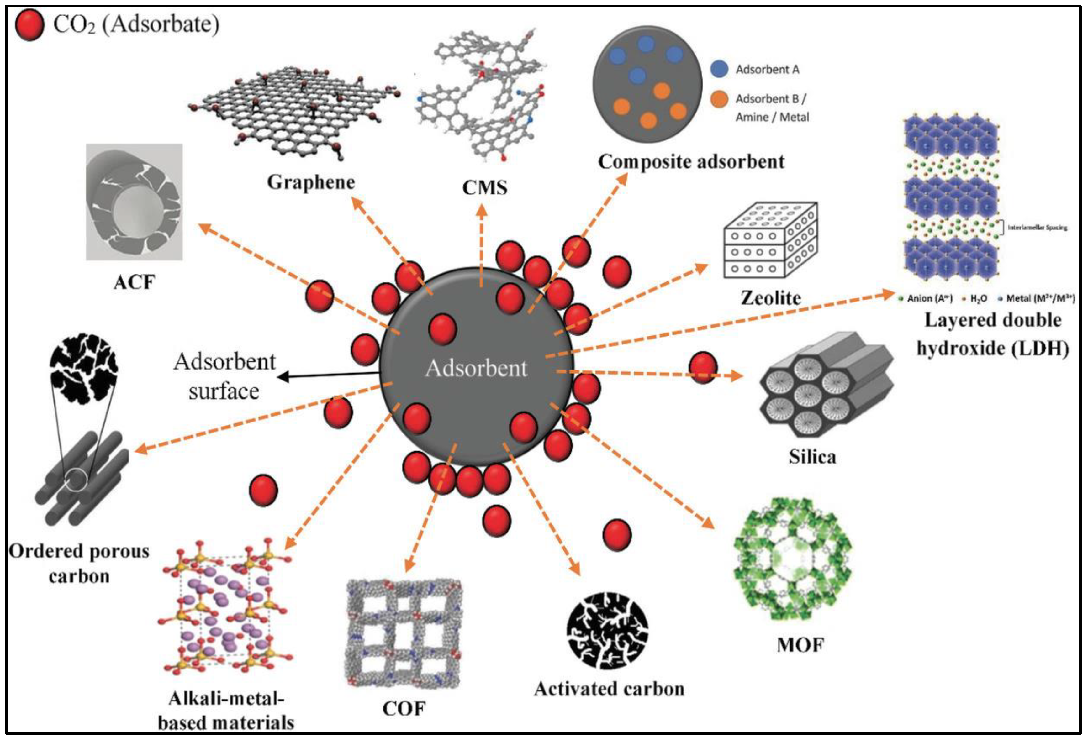
2.2. Adsorption
- 1.
- Pressure swing adsorption (PSA);
- 2.
- Temperature swing adsorption (TSA);
- 3.
- Electrical swing adsorption (ESA);
- 4.
- Vacuum Swing Adsorption (VSA).
3. Membrane Separation
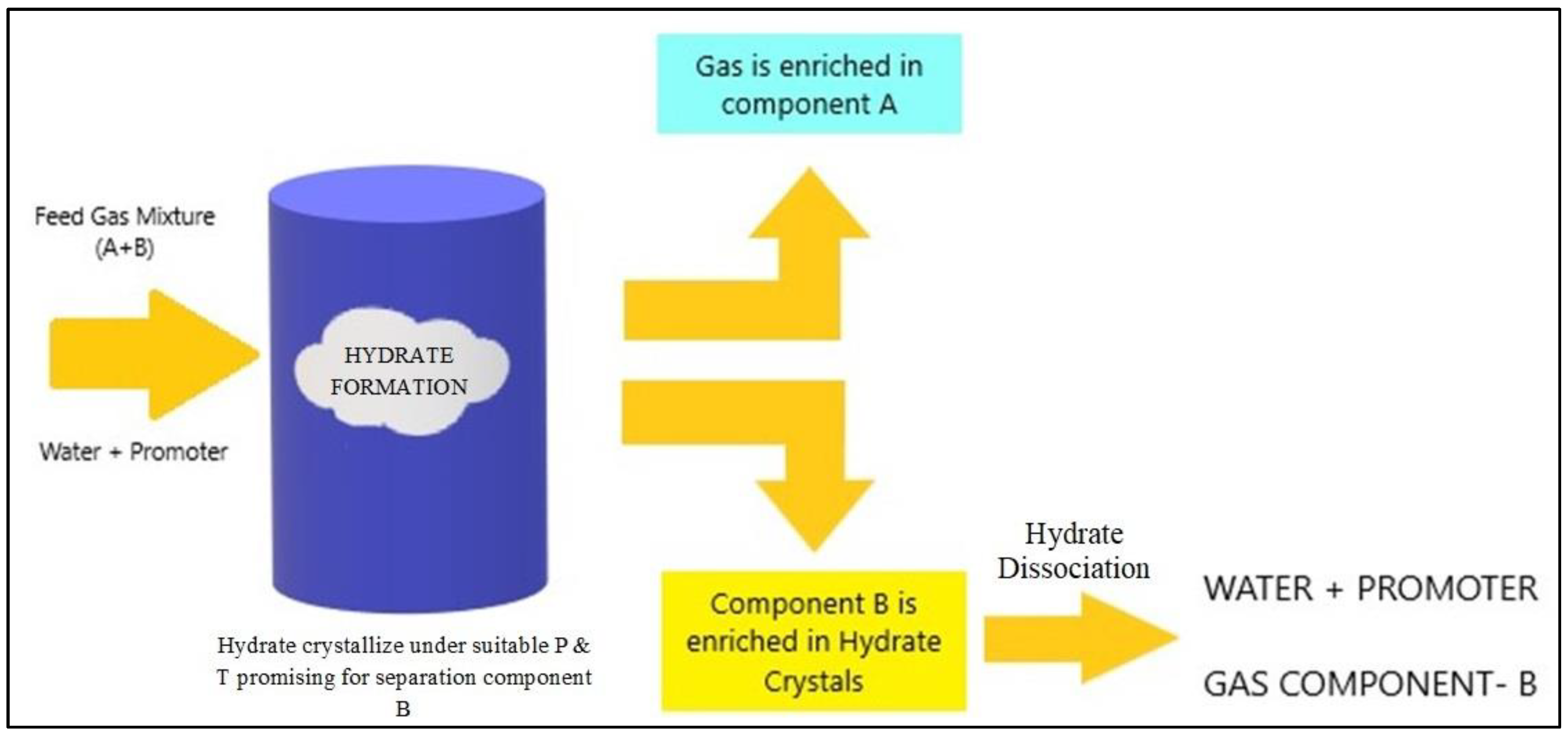
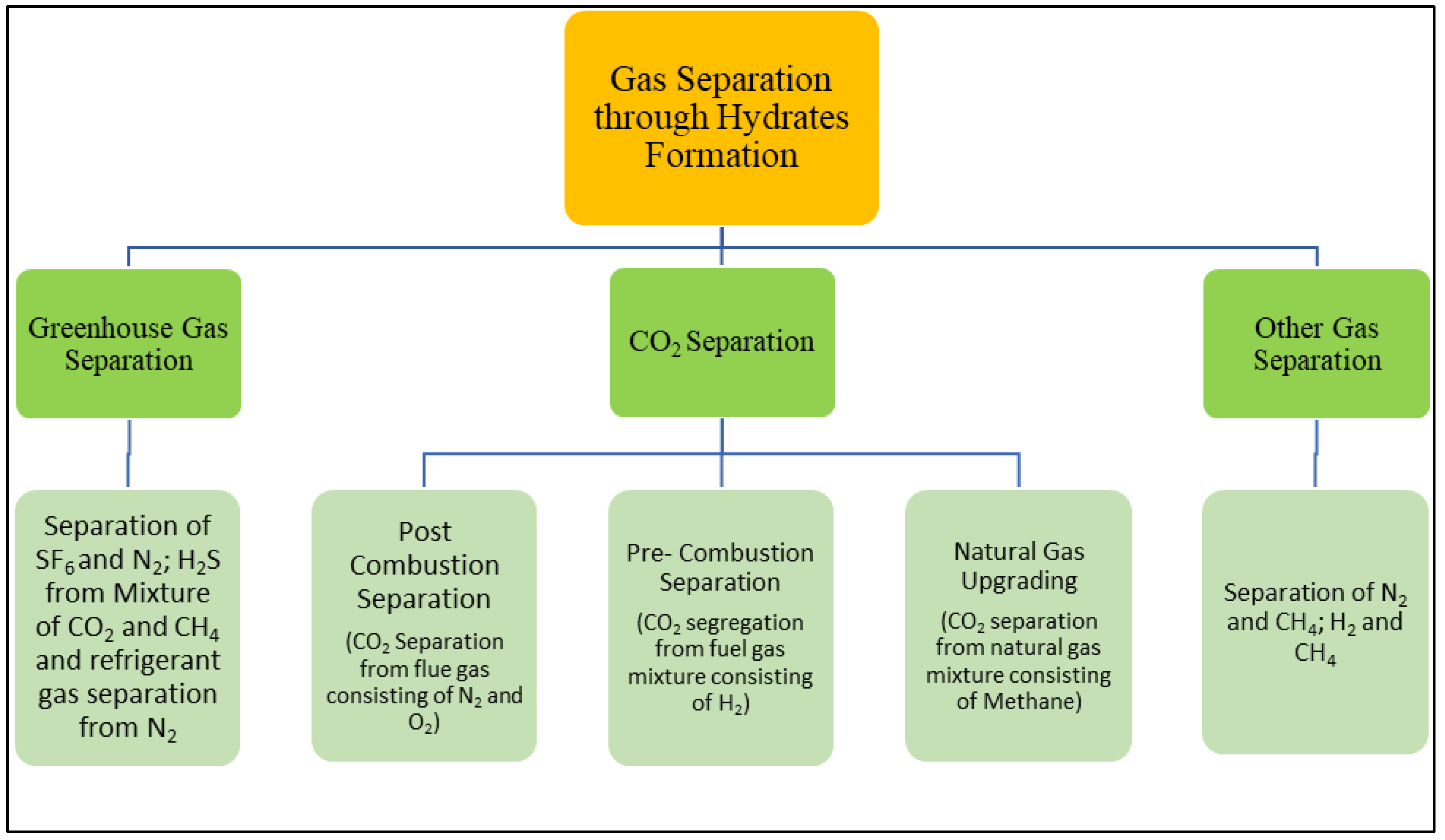
4. Hydrate-Based Separation
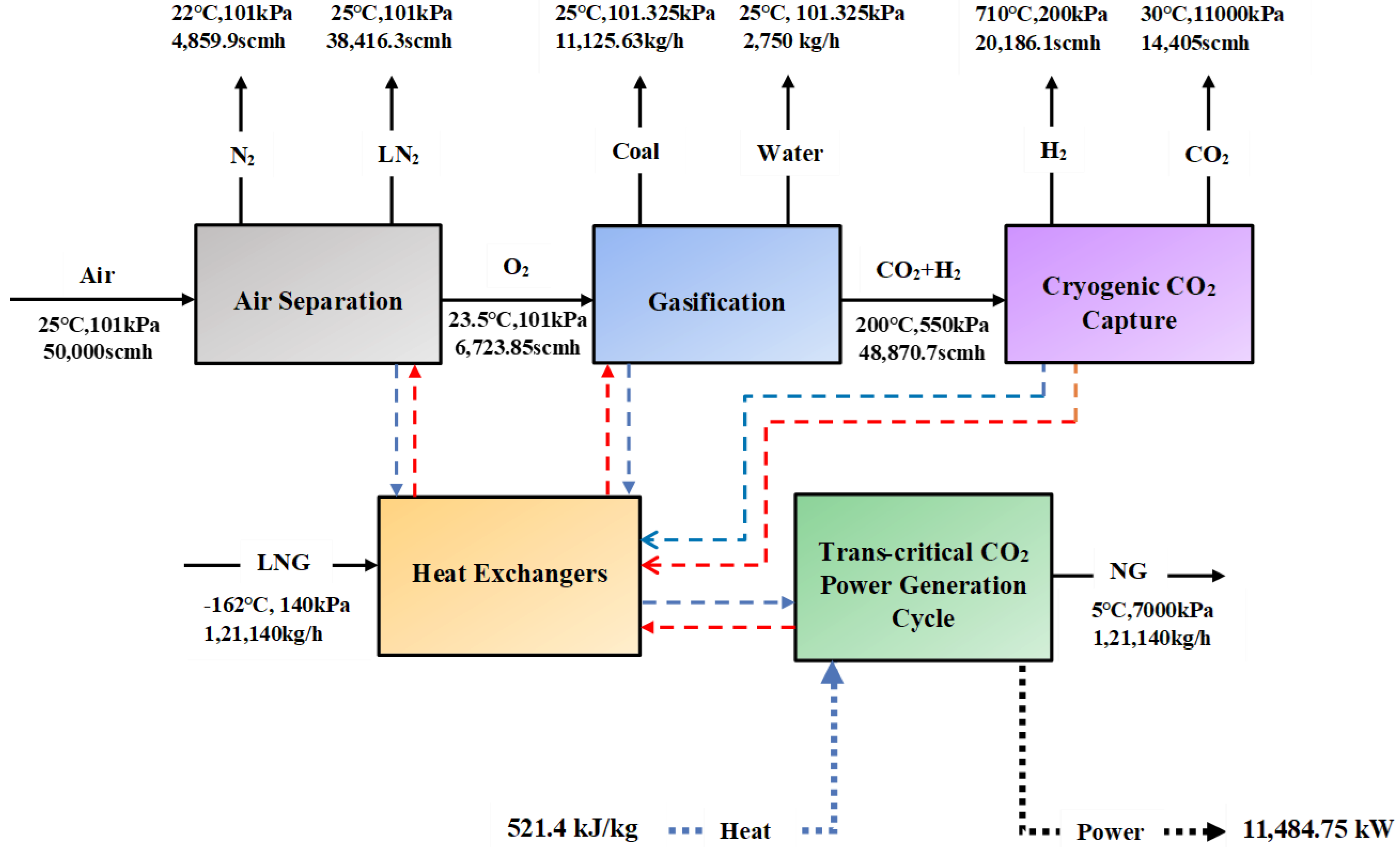
5. Cryogenic Distillation
6. Biological CO2 Capture/Separation
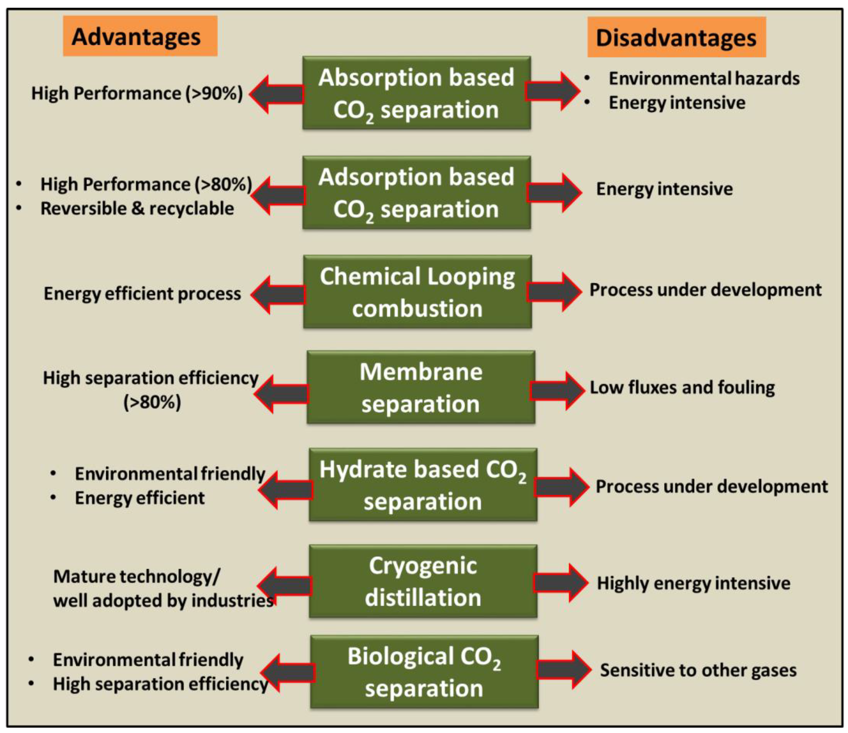
7. Comparison of Various CO2 Capture/Separation Process
8. Future Scopes
- Environmentally benign substitutes need to be developed for adsorption and absorption process;
- The use of biopolymers in gas-separation membranes requires extensive research;
- Process-related challenges need to be overcome to enhance the use of biological CO2 separation techniques at industrial levels.
- Identify suitable methods to optimize the energy consumption of different CO2 capture/separation processes;
- Longevity of the CO2 source (for example, cement plants, power plants, and steel);
- Distance between the CO2 generator and the storage facility;
- Onshore versus offshore storage and transportation;
- Transportation infrastructure type (pipeline trunks, road and rail networks, and cargo dock facilities).
9. Conclusions
Author Contributions
Funding
Data Availability Statement
Acknowledgments
Conflicts of Interest
References
- International Energy Agency. Global Energy Review: CO2 Emissions in 2021 Global Emissions Rebound Sharply to Highest Ever Level; International Energy Agency: Paris, France, 2021. [Google Scholar]
- Leung, D.Y.C.; Caramanna, G.; Maroto-Valer, M.M. An overview of current status of carbon dioxide capture and storage technologies. Renew. Sustain. Energy Rev. 2014, 39, 426–443. [Google Scholar] [CrossRef]
- Bhown, A.S.; Freeman, B.C. Analysis and Status of Post-Combustion Carbon Dioxide Capture Technologies. Environ. Sci. Technol. 2011, 45, 8624–8632. [Google Scholar] [CrossRef] [PubMed]
- Pandey, G.; Poothia, T.; Kumar, A. Hydrate based carbon capture and sequestration (HBCCS): An innovative approach towards decarbonization. Appl. Energy 2022, 326, 119900. [Google Scholar] [CrossRef]
- Aaron, D.; Tsouris, C. Separation of CO2 from Flue Gas: A Review. Sep. Sci. Technol. 2005, 40, 321–348. [Google Scholar] [CrossRef]
- Takamura, Y.; Aoki, J.; Uchida, S.; Narita, S. Application of high-pressure swing adsorption process for improvement of CO2 recovery system from flue gas. Can. J. Chem. Eng. 2001, 79, 812–816. [Google Scholar] [CrossRef]
- Clausse, M.; Merel, J.; Meunier, F. Numerical parametric study on CO2 capture by indirect thermal swing adsorption. Int. J. Greenh. Gas Control 2011, 5, 1206–1213. [Google Scholar] [CrossRef]
- Adanez, J.; Abad, A.; Garcia-Labiano, F.; Gayan, P.; de Diego, L.F. Progress in Chemical-Looping Combustion and Reforming technologies. Prog. Energy Combust. Sci. 2012, 38, 215–282. [Google Scholar] [CrossRef]
- Erlach, B.; Schmidt, M.; Tsatsaronis, G. Comparison of carbon capture IGCC with pre-combustion decarbonisation and with chemical-looping combustion. Energy 2011, 36, 3804–3815. [Google Scholar] [CrossRef]
- Wong, S.; Bioletti, R. Carbon Dioxide Separation Technologies. Available online: http://www.ipcc.ch/ (accessed on 23 November 2022).
- Songolzadeh, M.; Soleimani, M.; Takht Ravanchi, M.; Songolzadeh, R. Carbon Dioxide Separation from Flue Gases: A Technological Review Emphasizing Reduction in Greenhouse Gas Emissions. Sci. World J. 2014, 2014, 828131. [Google Scholar] [CrossRef]
- Simpson, A.P.; Simon, A.J. Second law comparison of oxy-fuel combustion and post-combustion carbon dioxide separation. Energy Convers. Manag. 2007, 48, 3034–3045. [Google Scholar] [CrossRef]
- Mondal, M.K.; Balsora, H.K.; Varshney, P. Progress and trends in CO2 capture/separation technologies: A review. Energy 2012, 46, 431–441. [Google Scholar] [CrossRef]
- Rackley, S.A. Absorption capture systems. In Carbon Capture and Storage, 2nd ed.; Elsevier: Amsterdam, The Netherlands, 2017; pp. 151–185. [Google Scholar]
- Sifat, N.S.; Haseli, Y. A Critical Review of CO2 Capture Technologies and Prospects for Clean Power Generation. Energies 2019, 12, 4143. [Google Scholar] [CrossRef]
- Theo, W.L.; Lim, J.S.; Hashim, H.; Mustaffa, A.A.; Ho, W.S. Review of pre-combustion capture and ionic liquid in carbon capture and storage. Appl. Energy 2016, 183, 1633–1663. [Google Scholar] [CrossRef]
- Yu, C.-H.; Huang, C.-H.; Tan, C.-S. A Review of CO2 Capture by Absorption and Adsorption. Aerosol Air Qual. Res. 2012, 12, 745–769. [Google Scholar] [CrossRef]
- Jansen, D.; Gazzani, M.; Manzolini, G.; van Dijk, E.; Carbo, M. Pre-combustion CO2 capture. Int. J. Greenh. Gas Control 2015, 40, 167–187. [Google Scholar] [CrossRef]
- Figueroa, J.D.; Fout, T.; Plasynski, S.I.; McIlvried, H.; Srivastava, R.D. Advances in CO2 Capture Technology—The U.S. Department of Energy’s Carbon Sequestration Program. Int. J. Greenh. Gas Control 2008, 2, 9–20. [Google Scholar] [CrossRef]
- Kim, Y.-S.; Yang, S.-M. Absorption of carbon dioxide through hollow fiber membranes using various aqueous absorbents. Sep. Purif. Technol. 2000, 21, 101–109. [Google Scholar] [CrossRef]
- Lee, S.C.; Choi, B.Y.; Lee, T.J.; Ryu, C.K.; Ahn, Y.S.; Kim, J.C. CO2 absorption and regeneration of alkali metal-based solid sorbents. Catal. Today 2006, 111, 385–390. [Google Scholar] [CrossRef]
- Hu, G.; Nicholas, N.J.; Smith, K.H.; Mumford, K.A.; Kentish, S.E.; Stevens, G.W. Carbon dioxide absorption into promoted potassium carbonate solutions: A review. Int. J. Greenh. Gas Control 2016, 53, 28–40. [Google Scholar] [CrossRef]
- Bosch, H.; Versteeg, G.F.; Van Swaaij, W.P.M. Kinetics of the reaction of CO2 with the sterically hindered amine 2-Amino-2-methylpropanol at 298 K. Chem. Eng. Sci. 1990, 45, 1167–1173. [Google Scholar] [CrossRef]
- Shrier, A.L.; Danckwerts, P.V. Carbon Dioxide Absorption into Amine-Promoted Potash Solutions. Ind. Eng. Chem. Fundam. 1969, 8, 415–423. [Google Scholar] [CrossRef]
- Feron, P.H.; Jansen, A. The production of carbon dioxide from flue gas by membrane gas absorption. Energy Convers. Manag. 1997, 38, S93–S98. [Google Scholar] [CrossRef]
- Bougie, F.; Iliuta, M.C. CO2 Absorption in Aqueous Piperazine Solutions: Experimental Study and Modeling. J. Chem. Eng. Data 2011, 56, 1547–1554. [Google Scholar] [CrossRef]
- Fredriksen, S.B.; Jens, K.-J. Oxidative Degradation of Aqueous Amine Solutions of MEA, AMP, MDEA, Pz: A Review. Energy Procedia 2013, 37, 1770–1777. [Google Scholar] [CrossRef]
- da Silva, C.F.N.; Dias, A.P.B.; Santana, A.P.R.; Pizzo, J.S.; de Souza, F.M.; Lazarin, A.M.; Sernaglia, R.L.; Andreotti, E.I.S. Retraction: Intercalation of Amines into Layered Calcium Phosphate and Their New Behavior for Copper Retention from Ethanolic Solution. Open J. Synth. Theory Appl. 2013, 2, 1–7. [Google Scholar] [CrossRef]
- Kozak, F.; Petig, A.; Morris, E.; Rhudy, R.; Thimsen, D. Chilled ammonia process for CO2 capture. Energy Procedia 2009, 1, 1419–1426. [Google Scholar] [CrossRef]
- Songolzadeh, M.; Ravanchi, M.T.; Soleimani, M. Carbon Dioxide Capture and Storage: A General Review on Adsorbents. Int. J. Chem. Mol. Eng. 2012, 6, 906–913. [Google Scholar] [CrossRef]
- Meisen, A.; Shuai, X. Research and development issues in CO2 capture. Energy Convers. Manag. 1997, 38, S37–S42. [Google Scholar] [CrossRef]
- Liu, H.; Liu, B.; Lin, L.-C.; Chen, G.; Wu, Y.; Wang, J.; Gao, X.; Lv, Y.; Pan, Y.; Zhang, X.; et al. A hybrid absorption–adsorption method to efficiently capture carbon. Nat. Commun. 2014, 5, 5147. [Google Scholar] [CrossRef]
- Mishra, A.K.; Ramaprabhu, S. Palladium nanoparticles decorated graphite nanoplatelets for room temperature carbon dioxide adsorption. Chem. Eng. J. 2012, 187, 10–15. [Google Scholar] [CrossRef]
- Abid, H.R.; Pham, G.H.; Ang, H.-M.; Tade, M.O.; Wang, S. Adsorption of CH4 and CO2 on Zr-metal organic frameworks. J. Colloid Interface Sci. 2012, 366, 120–124. [Google Scholar] [CrossRef]
- Choi, S.; Drese, J.H.; Jones, C.W. Adsorbent Materials for Carbon Dioxide Capture from Large Anthropogenic Point Sources. ChemSusChem 2009, 2, 796–854. [Google Scholar] [CrossRef]
- Jang, D.-I.; Park, S.-J. Influence of nickel oxide on carbon dioxide adsorption behaviors of activated carbons. Fuel 2012, 102, 439–444. [Google Scholar] [CrossRef]
- Anbia, M.; Hoseini, V. Development of MWCNT@MIL-101 hybrid composite with enhanced adsorption capacity for carbon dioxide. Chem. Eng. J. 2012, 191, 326–330. [Google Scholar] [CrossRef]
- Lee, Z.H.; Lee, K.T.; Bhatia, S.; Mohamed, A.R. Post-combustion carbon dioxide capture: Evolution towards utilization of nanomaterials. Renew. Sustain. Energy Rev. 2012, 16, 2599–2609. [Google Scholar] [CrossRef]
- Chiao, C.-H.; Chen, J.-L.; Lan, C.-R.; Chen, S.; Hsu, H.-W. Development of carbon dioxide capture and storage technology—Taiwan power company perspective. Sustain. Environ. Res. 2011, 21, 1–8. [Google Scholar]
- Li, J.-R.; Ma, Y.; McCarthy, M.C.; Sculley, J.; Yu, J.; Jeong, H.-K.; Balbuena, P.B.; Zhou, H.-C. Carbon dioxide capture-related gas adsorption and separation in metal-organic frameworks. Coord. Chem. Rev. 2011, 255, 1791–1823. [Google Scholar] [CrossRef]
- Dantas, T.L.P.; Luna, F.M.T.; Silva, I.J., Jr.; Torres, A.E.B.; Azevedo, D.C.S.; Rodrigues, A.E.; Moreira, R.F.P.M. Carbon dioxide–nitrogen separation through pressure swing adsorption. Chem. Eng. J. 2011, 172, 698–704. [Google Scholar] [CrossRef]
- Bolland, P.O.; Nord, P.L.O. Carbon Dioxide Emission Management in Power Generation; Wiley: New York, NY, USA, 2020. [Google Scholar]
- Boot-Handford, M.E.; Abanades, J.C.; Anthony, E.J.; Blunt, M.J.; Brandani, S.; Mac Dowell, N.; Fernández, J.R.; Ferrari, M.-C.; Gross, R.; Hallett, J.P.; et al. Carbon capture and storage update. Energy Environ. Sci. 2014, 7, 130–189. [Google Scholar] [CrossRef]
- Osman, A.I.; Hefny, M.; Abdel Maksoud, M.I.A.; Elgarahy, A.M.; Rooney, D.W. Recent advances in carbon capture storage and utilisation technologies: A review. Environ. Chem. Lett. 2021, 19, 797–849. [Google Scholar] [CrossRef]
- Kulkarni, A.R.; Sholl, D.S. Analysis of Equilibrium-Based TSA Processes for Direct Capture of CO2 from Air. Ind. Eng. Chem. Res. 2012, 51, 8631–8645. [Google Scholar] [CrossRef]
- Ritter, J.A. Radically New Adsorption Cycles for Carbon Dioxide Sequestration. In Proceedings of the University Coal Research Contractors Review Meeting, Pittsburgh, PA, USA, 2–3 June 2004. [Google Scholar]
- Yong, Z.; Mata, V.; Rodrigues, A. Adsorption of carbon dioxide at high temperature—A review. Sep. Purif. Technol. 2002, 26, 195–205. [Google Scholar] [CrossRef]
- Lai, J.Y.; Ngu, L.H.; Hashim, S.S. A review of CO2 adsorbents performance for different carbon capture technology processes conditions. Greenh. Gases Sci. Technol. 2021, 11, 1076–1117. [Google Scholar] [CrossRef]
- Zhang, Y.; Sunarso, J.; Liu, S.; Wang, R. Current status and development of membranes for CO2/CH4 separation: A review. Int. J. Greenh. Gas Control 2013, 12, 84–107. [Google Scholar] [CrossRef]
- Norahim, N.; Yaisanga, P.; Faungnawakij, K.; Charinpanitkul, T.; Klaysom, C. Recent Membrane Developments for CO2 Separation and Capture. Chem. Eng. Technol. 2018, 41, 211–223. [Google Scholar] [CrossRef]
- Dai, Z.; Noble, R.D.; Gin, D.L.; Zhang, X.; Deng, L. Combination of ionic liquids with membrane technology: A new approach for CO2 separation. J. Memb. Sci. 2016, 497, 1–20. [Google Scholar] [CrossRef]
- Ismail, A.F.; Chandra Khulbe, K.; Matsuura, T. Gas Separation Membranes; Springer International Publishing: Cham, Switzerland, 2015. [Google Scholar]
- Bodzek, M.; Konieczny, K.; Kwiecińska, A. Application of membrane processes in drinking water treatment–state of art. Desalin. Water Treat. 2011, 35, 164–184. [Google Scholar] [CrossRef]
- Brunetti, A.; Scura, F.; Barbieri, G.; Drioli, E. Membrane technologies for CO2 separation. J. Memb. Sci. 2010, 359, 115–125. [Google Scholar] [CrossRef]
- Bodzek, M.; Bohdziewicz, J.; Konieczny, K. Techniki Membranowe W Ochronie Srodowiska; Wydawnictwo Politechniki Slaskiej: Gliwice, Poland, 1997. [Google Scholar]
- Narabska, A. Membranes and Membrane Separation Techniques; UMK Publishing House: Kota Bharu, Malaysia, 1997. [Google Scholar]
- Adewole, J.K.; Ahmad, A.L.; Ismail, S.; Leo, C.P. Current challenges in membrane separation of CO2 from natural gas: A review. Int. J. Greenh. Gas Control 2013, 17, 46–65. [Google Scholar] [CrossRef]
- Liu, X.; Jin, H.; Li, Y.; Bux, H.; Hu, Z.; Ban, Y.; Yang, W. Metal–organic framework ZIF-8 nanocomposite membrane for efficient recovery of furfural via pervaporation and vapor permeation. J. Memb. Sci. 2013, 428, 498–506. [Google Scholar] [CrossRef]
- Zhang, Y.; Wang, R. Novel method for incorporating hydrophobic silica nanoparticles on polyetherimide hollow fiber membranes for CO2 absorption in a gas–liquid membrane contactor. J. Memb. Sci. 2014, 452, 379–389. [Google Scholar] [CrossRef]
- Zhang, Y.; Wang, R.; Zhang, L.; Fane, A.G. Novel single-step hydrophobic modification of polymeric hollow fiber membranes containing imide groups: Its potential for membrane contactor application. Sep. Purif. Technol. 2012, 101, 76–84. [Google Scholar] [CrossRef]
- Yan, S.; Fang, M.-X.; Zhang, W.-F.; Wang, S.-Y.; Xu, Z.-K.; Luo, Z.-Y.; Cen, K.-F. Experimental study on the separation of CO2 from flue gas using hollow fiber membrane contactors without wetting. Fuel Process. Technol. 2007, 88, 501–511. [Google Scholar] [CrossRef]
- Ghasem, N.; Al-Marzouqi, M.; Duidar, A. Effect of PVDF concentration on the morphology and performance of hollow fiber membrane employed as gas–liquid membrane contactor for CO2 absorption. Sep. Purif. Technol. 2012, 98, 174–185. [Google Scholar] [CrossRef]
- Mansourizadeh, A.; Ismail, A.F. A developed asymmetric PVDF hollow fiber membrane structure for CO2 absorption. Int. J. Greenh. Gas Control 2011, 5, 374–380. [Google Scholar] [CrossRef]
- Tomita, S.; Akatsu, S.; Ohmura, R. Experiments and thermodynamic simulations for continuous separation of CO2 from CH 4 + CO 2 gas mixture utilizing hydrate formation. Appl. Energy 2015, 146, 104–110. [Google Scholar] [CrossRef]
- He, J.; Liu, Y.; Ma, Z.; Deng, S.; Zhao, R.; Zhao, L. A Literature Research on the Performance Evaluation of Hydrate-based CO 2 Capture and Separation Process. Energy Procedia 2017, 105, 4090–4097. [Google Scholar] [CrossRef]
- Yang, M.; Song, Y.; Jiang, L.; Zhao, Y.; Ruan, X.; Zhang, Y.; Wang, S. Hydrate-based technology for CO2 capture from fossil fuel power plants. Appl. Energy 2014, 116, 26–40. [Google Scholar] [CrossRef]
- Xia, Z.-M.; Li, X.-S.; Chen, Z.-Y.; Li, G.; Yan, K.-F.; Xu, C.-G.; Lv, Q.-N.; Cai, J. Hydrate-based CO2 capture and CH4 purification from simulated biogas with synergic additives based on gas solvent. Appl. Energy 2016, 162, 1153–1159. [Google Scholar] [CrossRef]
- Kumar, A.; Veluswamy, H.P.; Jadhawar, P.; Chapoy, A.; Aman, Z. Gas Hydrates in Man-Made Environments: Applications, Economics, Challenges and Future Directions. In Status and Future Challenges for Non-Conventional Energy Sources Volume 1. Clean Energy Production Technologies; Springer: Singapore, 2022; pp. 173–192. [Google Scholar]
- Sabil, K.M.; Partoon, B. Recent advances on carbon dioxide capture through a hydrate-based gas separation process. Curr. Opin. Green Sustain. Chem. 2018, 11, 22–26. [Google Scholar] [CrossRef]
- Babu, P.; Linga, P.; Kumar, R.; Englezos, P. A review of the hydrate based gas separation (HBGS) process for carbon dioxide pre-combustion capture. Energy 2015, 85, 261–279. [Google Scholar] [CrossRef]
- Yang, M.; Zhou, H.; Wang, P.; Song, Y. Effects of additives on continuous hydrate-based flue gas separation. Appl. Energy 2018, 221, 374–385. [Google Scholar] [CrossRef]
- Li, L.; Fan, S.; Yang, G.; Chen, Q.; Zhao, J.; Wei, N.; Meng, W.; Fan, J.; Yang, H. Continuous simulation of the separation process of CO2/H2 by forming hydrate. Chem. Eng. Sci. X 2020, 7, 100067. [Google Scholar] [CrossRef]
- Arora, A.; Kumar, A.; Bhattacharjee, G.; Kumar, P.; Balomajumder, C. Effect of different fixed bed media on the performance of sodium dodecyl sulfate for hydrate based CO2 capture. Mater. Des. 2016, 90, 1186–1191. [Google Scholar] [CrossRef]
- Kumar, A.; Sakpal, T.; Linga, P.; Kumar, R. Impact of Fly Ash Impurity on the Hydrate-Based Gas Separation Process for Carbon Dioxide Capture from a Flue Gas Mixture. Ind. Eng. Chem. Res. 2014, 53, 9849–9859. [Google Scholar] [CrossRef]
- Kumar, A.; Bhattacharjee, G.; Barmecha, V.; Diwan, S.; Kushwaha, O.S. Influence of kinetic and thermodynamic promoters on post-combustion carbon dioxide capture through gas hydrate crystallization. J. Environ. Chem. Eng. 2016, 4, 1955–1961. [Google Scholar] [CrossRef]
- Veluswamy, H.P.; Premasinghe, K.P.; Linga, P. CO2 Hydrates—Effect of Additives and Operating Conditions on the Morphology and Hydrate Growth. Energy Procedia 2017, 105, 5048–5054. [Google Scholar] [CrossRef]
- Liu, Z.; Zeng, Y.; Wang, W. CO2 Hydrate Formation Promoted by a Bio-friendly Amino Acid L-Isoleucine. IOP Conf. Ser. Earth Environ. Sci. 2020, 474, 052054. [Google Scholar] [CrossRef]
- Singh, A.; Veluswamy, H.P. Investigation of Kinetics of Methane and Carbon Dioxide Hydrates in the Presence of Biobased Additives. Energy Fuels 2022, 36, 14315–14330. [Google Scholar] [CrossRef]
- Ozturk, M.; Panuganti, S.R.; Gong, K.; Cox, K.R.; Vargas, F.M.; Chapman, W.G. Modeling natural gas-carbon dioxide system for solid-liquid-vapor phase behavior. J. Nat. Gas Sci. Eng. 2017, 45, 738–746. [Google Scholar] [CrossRef]
- Göttlicher, G.; Pruschek, R. Comparison of CO2 removal systems for fossil-fuelled power plant processes. Energy Convers. Manag. 1997, 38, S173–S178. [Google Scholar] [CrossRef]
- Babar, M.; Bustam, M.A.; Ali, A.; Shah Maulud, A.; Shafiq, U.; Mukhtar, A.; Shah, S.N.; Maqsood, K.; Mellon, N.; Shariff, A.M. Thermodynamic data for cryogenic carbon dioxide capture from natural gas: A review. Cryogenics 2019, 102, 85–104. [Google Scholar] [CrossRef]
- Tuinier, M.J.; Hamers, H.P.; van Sint Annaland, M. Techno-economic evaluation of cryogenic CO2 capture—A comparison with absorption and membrane technology. Int. J. Greenh. Gas Control 2011, 5, 1559–1565. [Google Scholar] [CrossRef]
- Mehrpooya, M.; Esfilar, R.; Moosavian, S.M.A. Introducing a novel air separation process based on cold energy recovery of LNG integrated with coal gasification, transcritical carbon dioxide power cycle and cryogenic CO2 capture. J. Clean. Prod. 2017, 142, 1749–1764. [Google Scholar] [CrossRef]
- De Silva, G.P.D.; Ranjith, P.G.; Perera, M.S.A. Geochemical aspects of CO2 sequestration in deep saline aquifers: A review. Fuel 2015, 155, 128–143. [Google Scholar] [CrossRef]
- Daneshvar, E.; Wicker, R.J.; Show, P.L.; Bhatnagar, A. Biologically-mediated carbon capture and utilization by microalgae towards sustainable CO2 biofixation and biomass valorization—A review. Chem. Eng. J. 2022, 427, 130884. [Google Scholar] [CrossRef]
- Hakkarainen, J.; Ialongo, I.; Maksyutov, S.; Crisp, D. Analysis of four years of global XCO2 anomalies as seen by orbiting carbon observatory-2. Remote Sens. 2019, 11, 850. [Google Scholar] [CrossRef]
- Vieira, É.D.; da Graça Stupiello Andrietta, M.; Andrietta, S.R. Yeast biomass production: A new approach in glucose-limited feeding strategy. Braz. J. Microbiol. 2013, 44, 551–558. [Google Scholar] [CrossRef]
- Zhao, B.; Su, Y. Process effect of microalgal-carbon dioxide fixation and biomass production: A review. Renew. Sustain. Energy Rev. 2014, 31, 121–132. [Google Scholar] [CrossRef]
- Singh, J.; Gu, S. Commercialization potential of microalgae for biofuels production. Renew. Sustain. Energy Rev. 2010, 14, 2596–2610. [Google Scholar] [CrossRef]
- Usui, N.; Ikenouchi, M. The biological CO2 fixation and utilization project by RITE(1): Highly-effective photobioreactor system. Energy Convers. Manag. 1997, 38, S487–S492. [Google Scholar] [CrossRef]
- Samipour, S.; Ahmadi, A.; Manshadi, M.D.; Setoodeh, P. Challenges in Industrialization of Biological CO2 Capture; Elsevier Inc.: Amsterdam, The Netherlands, 2020. [Google Scholar]
- Guduru, R.K.; Gupta, A.A.; Dixit, U. Biological Processes for CO2 Capture; Elsevier Inc.: Amsterdam, The Netherlands, 2022. [Google Scholar]
- Wan, X.; Wang, X.; Wan, T.; Yan, Y.; Ye, Z.; Peng, X. Bio-inspired ferromagnetic graphene oxide/magnetic ionic liquid membrane for highly efficient CO2 separation. Appl. Mater. Today 2021, 24, 101164. [Google Scholar] [CrossRef]
- Russo, F.; Galiano, F.; Iulianelli, A.; Basile, A.; Figoli, A. Biopolymers for sustainable membranes in CO2 separation: A review. Fuel Process. Technol. 2021, 213, 106643. [Google Scholar] [CrossRef]
- Douskova, I.; Doucha, J.; Livansky, K.; Machat, J.; Novak, P.; Umysova, D.; Zachleder, V.; Vitova, M. Simultaneous flue gas bioremediation and reduction of microalgal biomass production costs. Appl. Microbiol. Biotechnol. 2009, 82, 179–185. [Google Scholar] [CrossRef] [PubMed]
- Ibn-Mohammed, T.; Greenough, R.; Taylor, S.; Ozawa-Meida, L.; Acquaye, A. Operational vs. embodied emissions in buildings—A review of current trends. Energy Build. 2013, 66, 232–245. [Google Scholar] [CrossRef]
- Goli, A.; Shamiri, A.; Talaiekhozani, A.; Eshtiaghi, N.; Aghamohammadi, N.; Aroua, M.K. An overview of biological processes and their potential for CO2 capture. J. Environ. Manage. 2016, 183, 41–58. [Google Scholar] [CrossRef]
- Wyczalek, F. Energy Independence—A Nation Running on Empty. In Proceedings of the 3rd International Energy Conversion Engineering Conference, San Francisco, CA, USA, 15–18 August 2005. [Google Scholar] [CrossRef]
- Wang, Y.; Zhao, L.; Otto, A.; Robinius, M.; Stolten, D. A Review of Post-combustion CO2 Capture Technologies from Coal-fired Power Plants. Energy Procedia 2017, 114, 650–665. [Google Scholar] [CrossRef]
- Damen, K.; van Troost, M.; Faaij, A.; Turkenburg, W. A comparison of electricity and hydrogen production systems with CO2 capture and storage. Part A: Review and selection of promising conversion and capture technologies. Prog. Energy Combust. Sci. 2006, 32, 215–246. [Google Scholar] [CrossRef]
- Rubin, E.; Rao, A.; Chen, C. Comparative assessments of fossil fuel power plants with CO2 capture and storage. In Greenhouse Gas Control Technologies 7; Elsevier: Amsterdam, The Netherlands, 2005; pp. 285–293. [Google Scholar]
- Porter, R.T.J.; Fairweather, M.; Pourkashanian, M.; Woolley, R.M. The range and level of impurities in CO2 streams from different carbon capture sources. Int. J. Greenh. Gas Control 2015, 36, 161–174. [Google Scholar] [CrossRef]
- Kanniche, M.; Le Moullec, Y.; Authier, O.; Hagi, H.; Bontemps, D.; Neveux, T.; Louis-Louisy, M. Up-to-date CO2 Capture in Thermal Power Plants. Energy Procedia 2017, 114, 95–103. [Google Scholar] [CrossRef]
- Dillon, D.J.; White, V.; Allam, R.J.; Wall, R.A.; Gibbins, J. Oxy Combustion Processes for CO2 Capture from Power Plant; Engineering Investigation Report; International Energy Agency (IEA): Paris, France, 2005; Volume 9. [Google Scholar]
- Zheng, L. Oxy-Fuel Combustion for Power Generation and Carbon Dioxide (CO2) Capture; Woodhead Publishing: Cambridge, UK, 2011. [Google Scholar]
- Hendriks, C. Carbon Dioxide Removal from Coal-Fired Power Plants; Energy & Environment; Springer: Dordrecht, The Netherlands, 1994; Volume 1. [Google Scholar]
- Olabi, A.G.; Obaideen, K.; Elsaid, K.; Wilberforce, T.; Sayed, E.T.; Maghrabie, H.M.; Abdelkareem, M.A. Assessment of the pre-combustion carbon capture contribution into sustainable development goals SDGs using novel indicators. Renew. Sustain. Energy Rev. 2022, 153, 111710. [Google Scholar] [CrossRef]
- Lyngfelt, A.; Linderholm, C. Chemical-looping Combustion of Solid Fuels—Technology Overview and Recent Operational Results in 100 kW Unit. Energy Procedia 2014, 63, 98–112. [Google Scholar] [CrossRef]
- Rackley, S.A. Introduction. In Carbon Capture and Storage; Elsevier: Amsterdam, The Netherlands, 2017; pp. 3–21. [Google Scholar]
- Gielen, D. The energy policy consequences of future CO2 capture and sequestration technologies. In Proceedings of the 2nd Annual Conference on Carbon Sequestration, Alexandria, Egypt, 6 May 2003; pp. 5–8. [Google Scholar]
- Audus, H. Leading options for the capture of CO2 at power stations. In Proceedings of the 5th International Conference on Greenhouse Gas Control Technologies (GHGT-5), Cairns, QLD, Australia, 13–16 August 2000. [Google Scholar]
- Zhang, X.; Song, Z.; Gani, R.; Zhou, T. Comparative Economic Analysis of Physical, Chemical, and Hybrid Absorption Processes for Carbon Capture. Ind. Eng. Chem. Res. 2020, 59, 2005–2012. [Google Scholar] [CrossRef]
- Tuinier, M.J.; van Sint Annaland, M.; Kramer, G.J.; Kuipers, J.A.M. Cryogenic CO2 capture using dynamically operated packed beds. Chem. Eng. Sci. 2010, 65, 114–119. [Google Scholar] [CrossRef]
- Li, J.; Zhang, H.; Gao, Z.; Fu, J.; Ao, W.; Dai, J. CO2 Capture with Chemical Looping Combustion of Gaseous Fuels: An Overview. Energy Fuels 2017, 31, 3475–3524. [Google Scholar] [CrossRef]
- Castel, C.; Bounaceur, R.; Favre, E. Membrane Processes for Direct Carbon Dioxide Capture From Air: Possibilities and Limitations. Front. Chem. Eng. 2021, 3, 668867. [Google Scholar] [CrossRef]
- Zhai, H.; Rubin, E.S. The Effects of Membrane-based CO2 Capture System on Pulverized Coal Power Plant Performance and Cost. Energy Procedia 2013, 37, 1117–1124. [Google Scholar] [CrossRef]
- Cuéllar-Franca, R.M.; Azapagic, A. Carbon capture, storage and utilisation technologies: A critical analysis and comparison of their life cycle environmental impacts. J. CO2 Util. 2015, 9, 82–102. [Google Scholar] [CrossRef]
- Lyngfelt, A.; Leckner, B. A 1000 MWth boiler for chemical-looping combustion of solid fuels—Discussion of design and costs. Appl. Energy 2015, 157, 475–487. [Google Scholar] [CrossRef]
- Moldenhauer, P.; Linderholm, C.; Rydén, M.; Lyngfelt, A. Avoiding CO2 capture effort and cost for negative CO2 emissions using industrial waste in chemical-looping combustion/gasification of biomass. Mitig. Adapt. Strateg. Glob. Chang. 2020, 25, 1–24. [Google Scholar] [CrossRef]
- Hong, W.Y. A techno-economic review on carbon capture, utilisation and storage systems for achieving a net-zero CO2 emissions future. Carbon Capture Sci. Technol. 2022, 3, 100044. [Google Scholar] [CrossRef]
- Kenarsari, S.D.; Yang, D.; Jiang, G.; Zhang, S.; Wang, J.; Russell, A.G.; Wei, Q.; Fan, M. Review of recent advances in carbon dioxide separation and capture. RSC Adv. 2013, 3, 22739. [Google Scholar] [CrossRef]
- Zoccali, M.; Donato, P.; Mondello, L. Recent advances in the coupling of carbon dioxide-based extraction and separation techniques. TrAC Trends Anal. Chem. 2019, 116, 158–165. [Google Scholar] [CrossRef]
- Yang, H.; Xu, Z.; Fan, M.; Gupta, R.; Slimane, R.B.; Bland, A.E.; Wright, I. Progress in carbon dioxide separation and capture: A review. J. Environ. Sci. 2008, 20, 14–27. [Google Scholar] [CrossRef]
- Zach, B.; Pluskal, J.; Šomplák, R.; Jadrný, J.; Šyc, M. Tool for optimization of energy consumption of membrane-based carbon capture. J. Environ. Manag. 2022, 320, 115913. [Google Scholar] [CrossRef]


| Solvent | Advantages | Disadvantages |
|---|---|---|
| PHYSICAL ABSORPTION | ||
| DME of PEG (Selexol) | Lower energy requirement for regeneration. Low toxicity, low corrosiveness, and lower vapor pressure | Temperature and pressure dependent. Low CO2 absorption capacity |
| Glycol Carbonate | ||
| Glycol | ||
| Methanol (Rectisol) | ||
| Fluorinated Solvent | ||
| CHEMICAL ABSORPTION | ||
| Alkanolamines (MEA, DEA, MDEA) | Rapid reaction Greater selectivity Reversible absorption Low-cost solvent | Limited CO2 loading capacity Greater apparatus corrosion rate Higher energy consumption |
| Amino acid and aq. amino acid salt | Nonvolatile solvent Possesses high surface tension Better performance than MEA with similar concentration | Lower effectiveness in presence of O2 |
| Ammonia | Unharmed in presence of SO2 and O2 in flue gas Corrosion free Lower energy requirement | Not suitable for postcombustion applications. Risk of dry CO2-NH3 explosion at high CO2 concentration. |
| Ionic Liquid | High thermal steadiness Low vapor pressure required Greater polarity Lower toxicity | Viscosity of the fluid increases with CO2 absorption |
| Aq. Piperazine (PZ) | Quick absorption kinetics Limited degradation rates during CO2 separation Insignificant thermal degradation in concentrated PZ solution Promising equilibrium characteristics | Low oxidative degradation of concentrated PZ |
| Sorbent | Operating Pressure (kPa) | Operating Temperature (K) | CO2 Capture Capacity (mol CO2/kg Sorbent) |
|---|---|---|---|
| CHEMICAL ADSORBENTS | |||
| Mesoporous (MgO) [34] | 101 | 298 | 1.8 |
| CaO nanopods [11] | 101 | 873 | 17.5 |
| CaO derived from nano-CaCO3 [11,34] | 101 | 923 | 16.7 |
| CaO-MgAl2O4 (spinel nanoparticles) [34] | 101 | 923 | 9.1 |
| Nano CaO/Al2O3 [34] | 101 | 923 | 6.0 |
| Lithium–Silicate [34] | - | 993 | 8.18 |
| CaO [34] | 100 | 873 | 17.3 |
| PHYSICAL ADSORBENTS | |||
| Activated Carbon [35] | 110 | 303 | 1.58 |
| NiO-ACs [35] | 101 | 298 | 2.227 |
| Na-Y [36] | 101.32 | 273 | 4.9 |
| NaKA [35] | 101.32 | 373 | 3.88 |
| MWNT [37] | 101 | 303 | 1.7 |
| CNT at (Cu3(btc)2) [36] | 1818 | 298 | 13.52 |
| MOF-177 [38] | 4545 | 298 | 33.5 |
| Pd-GNP Nanocomposite [39] | 1111 | 298 | 4.5 |
| Membrane Material | Analysis Condition/Absorbent | Gas Mixture | Temperature (in K) | CO2 Removal (%) |
|---|---|---|---|---|
| PVDF [58] | DI Water | CO2 | 299.15 | 1.84 |
| PVDF [58] | 0.5 M NaOH | 9:91 CO2:CH4 | 298.15 | 94.00 |
| Poly Propane (PP) [59] | 3 M Potassium glycinate | 14% CO2/air | 298.15 | 86.29 |
| PEI [60] | - | CO2 | 298.15 | 60.32 |
| PEI-fSiO2 [60,61] | 2 M Sodium taurinate | CO2 | 298.15 | 83.40 |
| PEEK [62] | 1.64 M activated K2CO3 | 13:87 CO2:N2 | 37–57 | 87.40 |
| PEEK [63] | 2.93 M DEA | 13:87 CO2:N2 | 37–57 | 93.10 |
| Parameter | Chemical Absorption [2,5,100,102,105] | Physical Absorption [2,5,16,100,102,105] | Adsorption [3,5,6,7,46,101,102,112] | Chemical Looping [8,9,83,102,103,108,114,118,119] | Hydrate-Based Separation [107,109,110,111,117] | Membrane [98,99,102,115,116] | Cryogenic [5,102,104,113] | Biological CO2 Separation [95,96,97,102,103,104] |
|---|---|---|---|---|---|---|---|---|
| Technique | Amine, Chilled Ammonia, and Amino Acid Salt Solvent | Rectisol, Selexol, Etc. Integrated Gasification Combined Cycle | Pressure- Temperature Swing adsorption | FeO, CuO, MnO and NiO | Natural gas hydrate cage structures | Polymeric inorganic and mixed membrane | Cryogenic distillation | Microbial and algal CO2 separation agents |
| CO2 Concentration | <30.4 | >59.3 | 28–34 | 3–8 | 35 | 11.8 | <90 | 3–5 |
| CO2 Capture (%) | 95 | >90 | <85 | 52–60 | 99 | 90 | 99.9 | 30 |
| Cost ($/Ton) | 26.2 | 25.1 | 6.94 | 16–24 | 40–100 | 3–10 | 32.7 | 1–40 |
| Purity | 99 | <99 | 99.98 | >96 | 99 | 95 | 99.95 | - |
Disclaimer/Publisher’s Note: The statements, opinions and data contained in all publications are solely those of the individual author(s) and contributor(s) and not of MDPI and/or the editor(s). MDPI and/or the editor(s) disclaim responsibility for any injury to people or property resulting from any ideas, methods, instructions or products referred to in the content. |
© 2023 by the authors. Licensee MDPI, Basel, Switzerland. This article is an open access article distributed under the terms and conditions of the Creative Commons Attribution (CC BY) license (https://creativecommons.org/licenses/by/4.0/).
Share and Cite
Rath, G.K.; Pandey, G.; Singh, S.; Molokitina, N.; Kumar, A.; Joshi, S.; Chauhan, G. Carbon Dioxide Separation Technologies: Applicable to Net Zero. Energies 2023, 16, 4100. https://doi.org/10.3390/en16104100
Rath GK, Pandey G, Singh S, Molokitina N, Kumar A, Joshi S, Chauhan G. Carbon Dioxide Separation Technologies: Applicable to Net Zero. Energies. 2023; 16(10):4100. https://doi.org/10.3390/en16104100
Chicago/Turabian StyleRath, Gourav Kumar, Gaurav Pandey, Sakshi Singh, Nadezhda Molokitina, Asheesh Kumar, Sanket Joshi, and Geetanjali Chauhan. 2023. "Carbon Dioxide Separation Technologies: Applicable to Net Zero" Energies 16, no. 10: 4100. https://doi.org/10.3390/en16104100
APA StyleRath, G. K., Pandey, G., Singh, S., Molokitina, N., Kumar, A., Joshi, S., & Chauhan, G. (2023). Carbon Dioxide Separation Technologies: Applicable to Net Zero. Energies, 16(10), 4100. https://doi.org/10.3390/en16104100