

Experimental Studies on the Influence of Spatial Orientation of a Passive Air Solar Collector on Its Efficiency
 ,
,  ,
,  ,
,  and
and 
Abstract
:1. Introduction
2. Experimental Methods
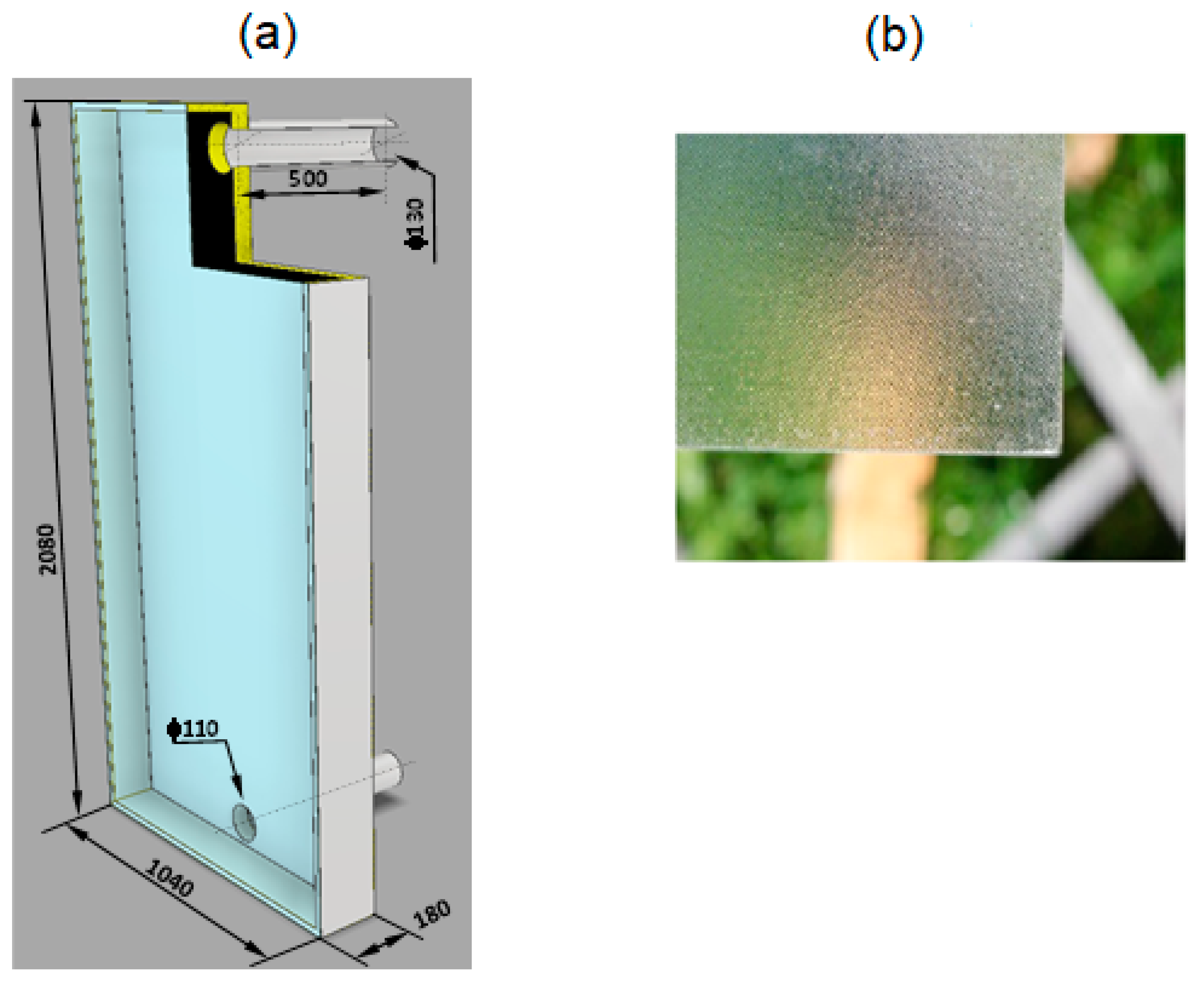
2.1. The Construction of a Prototype Flat Air Solar Collector
2.2. Measuring Equipment
2.3. The Scope of Research
2.4. Conversion of Measurement Data
3. Data Reduction
3.1. Air Temperature Increase in the Collector
3.2. The Velocity of the Air Flow through the Collector
3.3. Collector’s Heat Flux
3.4. Collector Efficiency
4. Summary and Conclusions
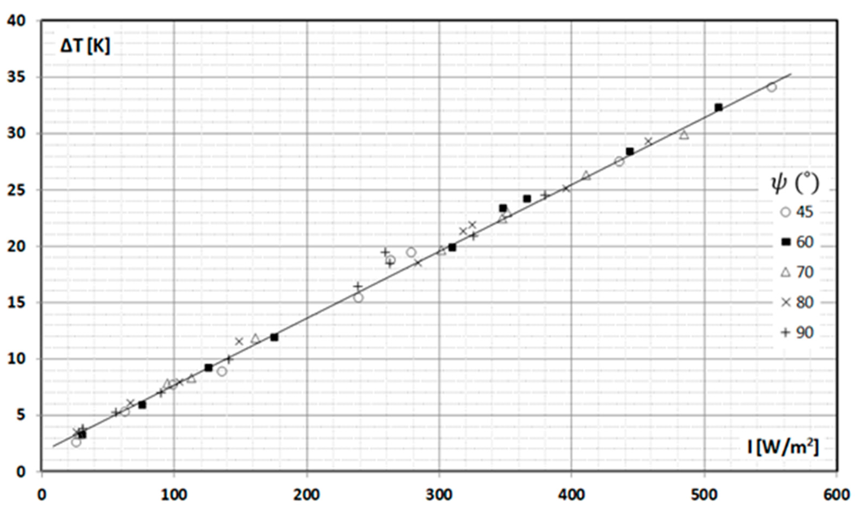
- an increase in the temperature of the air flowing through the collector depended on the radiation intensity (ΔT max = 35 K for I = 550 W/m2) and did not depend on the collector’s inclination;
- deflection of the collector from the vertical changed the air flow rate through the collector while maintaining the other parameters unchanged;
- tilting the collector backwards by 10° resulted in a 10% increase in the velocity of air flow through the collector. Further deflection of the collector backward caused a decrease in the value of the air flow velocity, regardless of the radiation intensity;
- further tests (including CFD) are necessary to check the reasons for the increase in the air flow velocity through the manifold when it is deviated from the vertical and what effect the length of the connection pipes–inlet ducts has on the value of the optimal angle of the collector deflection.
Author Contributions
Funding
Conflicts of Interest
Nomenclature
| A | collector aperture area [m2] |
| cp | specific heat of air at constant pressure [J/kgK] |
| din | inner diameter of the inlet/outlet duct [m] |
| I | radiation intensity [W/m2] |
| L | length of air inlet/outlet duct (connections) [m] |
| air mass flow rate [kg/s] | |
| T | air temperature [K] |
| Q | collector thermal power [W] |
| w | average air velocity [m/s] |
| Greek letters | |
| ε | the emissivity coefficient of the absorber surface [-] |
| η | collector efficiency [-] |
| ρ | air density [kg/m3] |
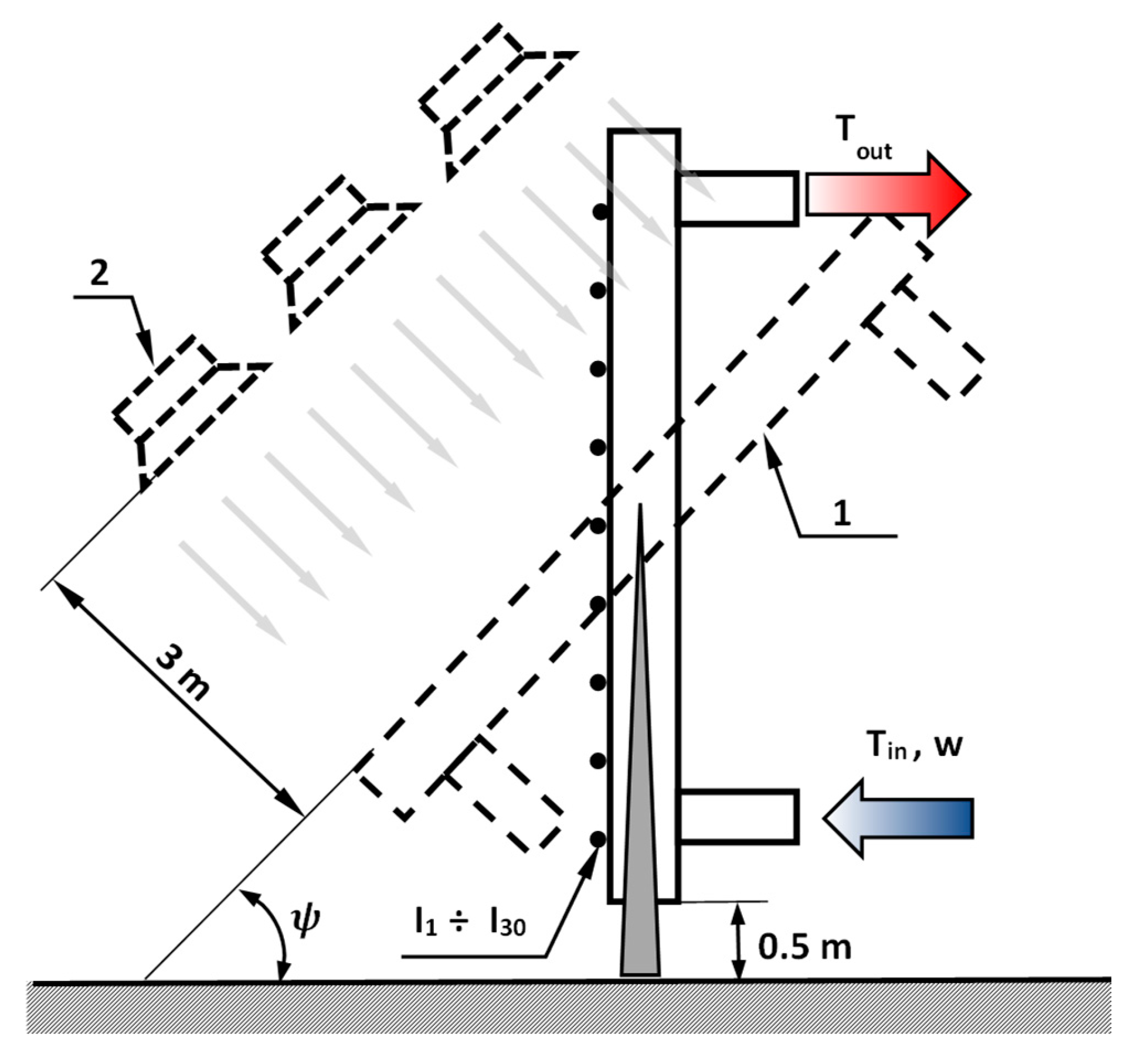
| ψ | the angle of deviation of the back surface of the collector from the horizontal plane [°] |
References
- Francesconi, M.; Antonelli, M.; Desideri, U. Assessment of the Optical Efficiency in Solar Collectors: Experimental Method for a Concentrating Solar Power. Therm. Sci. Eng. Prog. 2023, 40, 101740. [Google Scholar] [CrossRef]
- Zhao, K.; Jin, H.; Gai, Z.; Hong, H. A Thermal Efficiency-Enhancing Strategy of Parabolic Trough Collector Systems by Cascadingly Applying Multiple Solar Selective-Absorbing Coatings. Appl. Energy 2022, 309, 118508. [Google Scholar] [CrossRef]
- Qiu, Y.; Xu, Y.; Li, Q.; Wang, J.; Wang, Q.; Liu, B. Efficiency Enhancement of a Solar Trough Collector by Combining Solar and Hot Mirrors. Appl. Energy 2021, 299, 117290. [Google Scholar] [CrossRef]
- Alomar, O.R.; Abd, H.M.; Mohamed Salih, M.M. Efficiency Enhancement of Solar Air Heater Collector by Modifying Jet Impingement with V-Corrugated Absorber Plate. J. Energy Storage 2022, 55, 105535. [Google Scholar] [CrossRef]
- Bhowmik, H.; Amin, R. Efficiency Improvement of Flat Plate Solar Collector Using Reflector. Energy Rep. 2017, 3, 119–123. [Google Scholar] [CrossRef]
- Shaaban, S. Enhancement of the Solar Trough Collector Efficiency by Optimizing the Reflecting Mirror Profile. Renew. Energy 2021, 176, 40–49. [Google Scholar] [CrossRef]
- Sheikholeslami, M.; Jafaryar, M.; Barzegar Gerdroodbary, M.; Alavi, A.H. Influence of Novel Turbulator on Efficiency of Solar Collector System. Environ. Technol. Innov. 2022, 26, 102383. [Google Scholar] [CrossRef]
- Caldarelli, A.; Gaudino, E.; De Luca, D.; Farooq, U.; Musto, M.; Di Gennaro, E.; Russo, R. Low Emissivity Thin Film Coating to Enhance the Thermal Conversion Efficiency of Selective Solar Absorber in High Vacuum Flat Plate Collectors. Thin Solid Film. 2023, 764, 139632. [Google Scholar] [CrossRef]
- Li, Q.; Flamant, G.; Yuan, X.; Neveu, P.; Luo, L. Compact Heat Exchangers: A Review and Future Applications for a New Generation of High Temperature Solar Receivers. Renew. Sustain. Energy Rev. 2011, 15, 4855–4875. [Google Scholar] [CrossRef]
- Ajbar, W.; Hernández, J.A.; Parrales, A.; Torres, L. Thermal Efficiency Improvement of Parabolic Trough Solar Collector Using Different Kinds of Hybrid Nanofluids. Case Stud. Therm. Eng. 2023, 42, 102759. [Google Scholar] [CrossRef]
- Shojaeizadeh, E.; Veysi, F.; Habibi, H.; Goodarzi, K.; Habibi, M. Thermal Efficiency Investigation of a Ferrofluid-Based Cylindrical Solar Collector with a Helical Pipe Receiver under the Effect of Magnetic Field. Renew. Energy 2021, 176, 198–213. [Google Scholar] [CrossRef]
- Gao, D.; Wu, L.; Hao, Y.; Pei, G. Ultrahigh-Efficiency Solar Energy Harvesting via a Non-Concentrating Evacuated Aerogel Flat-Plate Solar Collector. Renew. Energy 2022, 196, 1455–1468. [Google Scholar] [CrossRef]
- Peng, W.; Sadaghiani, O.K. Using a Sunrays Trap in Direct-Absorption Solar Collector (DASC) to Enhance the Thermal Efficiency of Collector. Therm. Sci. Eng. Prog. 2020, 20, 100740. [Google Scholar] [CrossRef]
- Ahmadlouydarab, M.; Anari, T.D.; Akbarzadeh, A. Experimental Study on Cylindrical and Flat Plate Solar Collectors’ Thermal Efficiency Comparison. Renew. Energy 2022, 190, 848–864. [Google Scholar] [CrossRef]
- Farhana, K.; Kadirgama, K.; Mohammed, H.A.; Ramasamy, D.; Samykano, M.; Saidur, R. Analysis of Efficiency Enhancement of Flat Plate Solar Collector Using Crystal Nano-Cellulose (CNC) Nanofluids. Sustain. Energy Technol. Assess. 2021, 45, 101049. [Google Scholar] [CrossRef]
- Mahbubul, I.M.; Khan, M.M.A.; Ibrahim, N.I.; Ali, H.M.; Al-Sulaiman, F.A.; Saidur, R. Carbon Nanotube Nanofluid in Enhancing the Efficiency of Evacuated Tube Solar Collector. Renew. Energy 2018, 121, 36–44. [Google Scholar] [CrossRef]
- Kaya, H.; Alkasem, M.; Arslan, K. Effect of Nanoparticle Shape of Al2O3/Pure Water Nanofluid on Evacuated U-Tube Solar Collector Efficiency. Renew. Energy 2020, 162, 267–284. [Google Scholar] [CrossRef]
- Yan, S.-R.; Golzar, A.; Sharifpur, M.; Meyer, J.P.; Liu, D.-H.; Afrand, M. Effect of U-Shaped Absorber Tube on Thermal-Hydraulic Performance and Efficiency of Two-Fluid Parabolic Solar Collector Containing Two-Phase Hybrid Non-Newtonian Nanofluids. Int. J. Mech. Sci. 2020, 185, 105832. [Google Scholar] [CrossRef]
- Norouzi, A.M.; Siavashi, M.; Khaliji Oskouei, M. Efficiency Enhancement of the Parabolic Trough Solar Collector Using the Rotating Absorber Tube and Nanoparticles. Renew. Energy 2020, 145, 569–584. [Google Scholar] [CrossRef]
- Alklaibi, A.M.; Sundar, L.S.; Sousa, A.C.M. Experimental Analysis of Exergy Efficiency and Entropy Generation of Diamond/Water Nanofluids Flow in a Thermosyphon Flat Plate Solar Collector. Int. Commun. Heat Mass Transf. 2021, 120, 105057. [Google Scholar] [CrossRef]
- Mallah, A.R.; Zubir, M.N.M.; Alawi, O.A.; Kazi, S.N.; Ahmed, W.; Sadri, R.; Kasaeian, A. Experimental Study on the Effects of Multi-Resonance Plasmonic Nanoparticles for Improving the Solar Collector Efficiency. Renew. Energy 2022, 187, 1204–1223. [Google Scholar] [CrossRef]
- Said, Z.; Sharma, P.; Sundar, L.S.; Li, C.; Tran, D.C.; Khoa Pham, N.D.; Nguyen, X.P. Improving the Thermal Efficiency of a Solar Flat Plate Collector Using MWCNT-Fe3O4/Water Hybrid Nanofluids and Ensemble Machine Learning. Case Stud. Therm. Eng. 2022, 40, 102448. [Google Scholar] [CrossRef]
- Tavakoli, M.; Soufivand, M.R. Investigation of Entropy Generation, PEC, and Efficiency of Parabolic Solar Collector Containing Water/Al2O3−MWCNT Hybrid Nanofluid in the Presence of Finned and Perforated Twisted Tape Turbulators Using a Two-Phase Flow Scheme. Eng. Anal. Bound. Elem. 2023, 148, 324–335. [Google Scholar] [CrossRef]
- Khetib, Y.; Sedraoui, K.; Melaibari, A.A.; Alsulami, R. The Numerical Investigation of Spherical Grooves on Thermal–Hydraulic Behavior and Exergy Efficiency of Two-Phase Hybrid MWCNT-Al2O3/Water Nanofluid in a Parabolic Solar Collector. Sustain. Energy Technol. Assess. 2021, 47, 101530. [Google Scholar] [CrossRef]
- Abu-Hamdeh, N.H.; Khoshaim, A.; Alzahrani, M.A.; Hatamleh, R.I. Study of the Flat Plate Solar Collector’s Efficiency for Sustainable and Renewable Energy Management in a Building by a Phase Change Material: Containing Paraffin-Wax/Graphene and Paraffin-Wax/Graphene Oxide Carbon-Based Fluids. J. Build. Eng. 2022, 57, 104804. [Google Scholar] [CrossRef]
- Choudhary, S.; Sachdeva, A.; Kumar, P. Time-Based Analysis of Stability and Thermal Efficiency of Flat Plate Solar Collector Using Iron Oxide Nanofluid. Appl. Therm. Eng. 2021, 183, 115931. [Google Scholar] [CrossRef]
- Dutkowski, K.; Kruzel, M.; Bohdal, T. Experimental Studies of the Influence of Microencapsulated Phase Change Material on Thermal Parameters of a Flat Liquid Solar Collector. Energies 2021, 14, 5135. [Google Scholar] [CrossRef]
- Bohdal, T.; Dutkowski, K.; Kruzel, M. Experimental Studies of the Effect of Microencapsulated PCM Slurry on the Efficiency of a Liquid Solar Collector. Materials 2022, 15, 4493. [Google Scholar] [CrossRef]
- Feng, L.; Liu, J.; Lu, H.; Chen, Y.; Wu, S. A Parametric Study on the Efficiency of a Solar Evacuated Tube Collector Using Phase Change Materials: A Transient Simulation. Renew. Energy 2022, 199, 745–758. [Google Scholar] [CrossRef]
- Şevik, S.; Özdilli, Ö.; Abuşka, M. Experimental investigation of relative roughness height effect in solar air collector with convex dimples. Renew. Energy 2022, 194, 100–116. [Google Scholar] [CrossRef]
- Rani, P.; Tripathy, P.P. Experimental investigation on heat transfer performance of solar collector with baffles and semicircular loops fins under varied air mass flow rates. Int. J. Therm. Sci. 2022, 178, 107597. [Google Scholar] [CrossRef]
- Chabane, F.; Aouissi, Z. Experimental investigations on the thermal efficiency of a solar air collector with transverse rectangular baffles incline by an angle of 135°. Energy Built Environ. 2023. [Google Scholar] [CrossRef]
- Öztürk, M.; Çiftçi, E. Upgrading the performance of a solar air collector with flexible aluminum air ducts and graphene nanoplatelet-enhanced absorber coating. Therm. Sci. Eng. Prog. 2023, 40, 101760. [Google Scholar] [CrossRef]
- Li, J.; Qu, C.; Li, C.; Liu, X.; Novakovic, V. Technical and economic performance analysis of large flat plate solar collector coupled air source heat pump heating system. Energy Build 2022, 277, 112564. [Google Scholar] [CrossRef]
- Lingayat, A.; Chandramohan, V.P. Numerical investigation on solar air collector and its practical application in the indirect solar dryer for banana chips drying with energy and exergy analysis. Therm. Sci. Eng. Prog. 2021, 26, 101077. [Google Scholar] [CrossRef]
- Hu, J.; Guo, M.; Guo, J.; Zhang, G.; Zhang, Y. Numerical and experimental investigation of solar air collector with internal swirling flow. Renew. Energy 2020, 162, 2259–2271. [Google Scholar] [CrossRef]
- Reddy, J.; Roy, S.; Das Jagadish, B. Performance evaluation of sand coated absorber based solar air collector. J. Build. Eng. 2021, 44, 102973. [Google Scholar] [CrossRef]
- Dong, Z.; Chang, L.; Jianjun, Z.; Jinlong, J.; Zhoujian, A.; Linjun, W. Thermal economic analysis of a double-channel solar air collector coupled with draught fan: Based on energy grade. Renew. Energy 2021, 170, 936–947. [Google Scholar] [CrossRef]
- Selimefendigil, F.; Sirin, C.; Ghachem, K.; Kolsi, L.; Alqahtani, T.; Algarni, S. Enhancing the performance of a greenhouse drying system by using triple-flow solar air collector with nano-enhanced absorber coating. Case Stud. Therm. Eng. 2022, 34, 102011. [Google Scholar] [CrossRef]
- PN-EN 12976-2:2019-05. 2019. Available online: https://pdfcoffee.com/ashrae-93-77pdf-pdf-free.html (accessed on 14 March 2023).
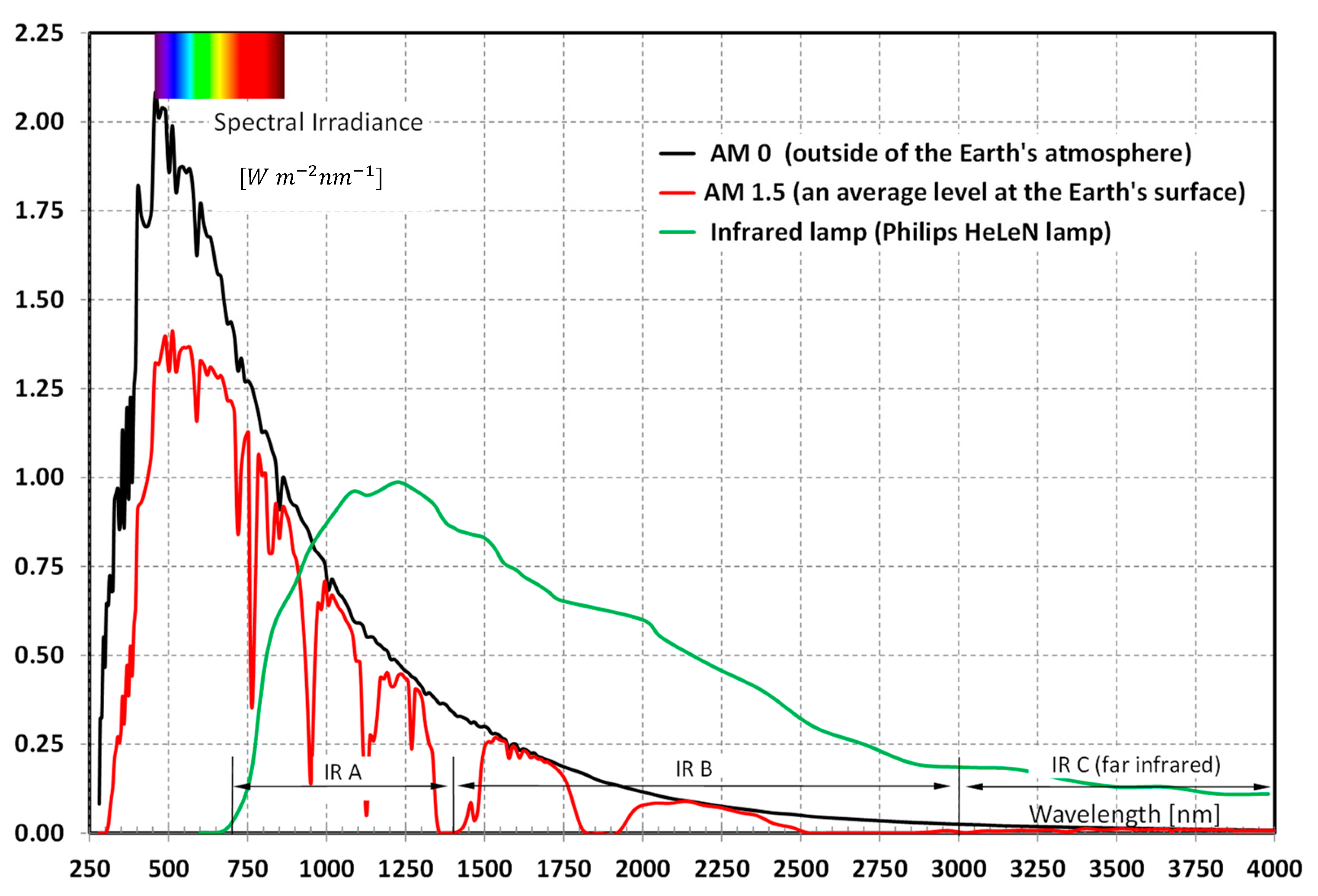
- Reference Solar Spectral Irradiances. Available online: https://www.ossila.com/en-pl/pages/standard-solar-spectrum (accessed on 15 April 2023).


Disclaimer/Publisher’s Note: The statements, opinions and data contained in all publications are solely those of the individual author(s) and contributor(s) and not of MDPI and/or the editor(s). MDPI and/or the editor(s) disclaim responsibility for any injury to people or property resulting from any ideas, methods, instructions or products referred to in the content. |
© 2023 by the authors. Licensee MDPI, Basel, Switzerland. This article is an open access article distributed under the terms and conditions of the Creative Commons Attribution (CC BY) license (https://creativecommons.org/licenses/by/4.0/).
Share and Cite
Dutkowski, K.; Kruzel, M.; Fiuk, J.; Rokosz, K.; Michalska-Pożoga, I.; Szczepanek, M. Experimental Studies on the Influence of Spatial Orientation of a Passive Air Solar Collector on Its Efficiency. Energies 2023, 16, 4125. https://doi.org/10.3390/en16104125
Dutkowski K, Kruzel M, Fiuk J, Rokosz K, Michalska-Pożoga I, Szczepanek M. Experimental Studies on the Influence of Spatial Orientation of a Passive Air Solar Collector on Its Efficiency. Energies. 2023; 16(10):4125. https://doi.org/10.3390/en16104125
Chicago/Turabian StyleDutkowski, Krzysztof, Marcin Kruzel, Jacek Fiuk, Krzysztof Rokosz, Iwona Michalska-Pożoga, and Marcin Szczepanek. 2023. "Experimental Studies on the Influence of Spatial Orientation of a Passive Air Solar Collector on Its Efficiency" Energies 16, no. 10: 4125. https://doi.org/10.3390/en16104125