Abstract
In recent times, DC microgrids (MGs) have received significant attention due to environmental concerns and the demand for clean energies. Energy storage systems (ESSs) and photovoltaic (PV) systems are parts of DC MGs. This paper expands on the modeling and control of non-isolated, non-inverting four-switch buck-boost (FSBB) synchronous converters, which interface with a wide range of low-power electronic appliances. The proposed power converter can work efficiently both independently and in DC MGs. The charging and discharging of the battery are analyzed using the FSBB converter at a steady state in continuous conduction mode (CCM). A boost converter is connected to a PV system, which is then connected in parallel to the battery to provide voltages at the DC bus. Finally, another FSBB converter is connected to a resistive load that successfully performs the boost-and-buck operation with smooth transitions. Since these power converters possess uncertainties and non-linearities, it is not suitable to design linear controllers for these systems. Therefore, the controlling mechanism for these converters’ operation is based on the sliding mode control (SMC). In this study, various macro-level interests were achieved using SMC. The MATLAB Simulink results successfully prove the precise reference tracking and robust stability in different operating modes of DC–DC converters in a MG structure.
1. Introduction
Non-conventional power sources are decent, natural, and abundant. They are possibly accessible free of cost and are effective if the power-transformation mechanism is improved [1]. The demand for electrical energy is constantly growing because of population growth and the Industrial Revolution [2]. The power-production industry suffers various problems like the continuous supply of energy at lower costs. The majority of electrical energy is still produced from non-renewable energy resources. Therefore, fossil fuels are depleting rapidly. Technically, renewable energy systems (RESs) have provided a base for modern research aimed at the production of DC distribution systems. Luckily, research and development in recent years has revealed that it is possible to link commercial grids with RESs, and that this process is also financially and technically viable. In the past few years, microgrids (MGs) have appeared as favorable means of unifying and synchronizing the task of distributed power resources [3]. These MGs are often deemed appropriate for increasing the flexibility of distribution systems, as well as integrating several RESs [4], making them suitable for a wide range of applications [5].
Therefore, DC MGs are receiving greater focus with the integration and contribution of numerous power suppliers; for instance, smart constructions and smart communities are of significant importance because of their considerable energy-generation capacity. Furthermore, PV panels and energy-storage systems (ESSs) are fundamental components of DC MGs. These RESs encompass PV systems, wind-turbine systems, geothermal and tidal systems, etc., and have received significant attention in recent years because of the increased interest in clean energies. Since these RESs cannot deliver steady power for consumers, it is necessary to use them along with the ESSs in hybrid power systems. Thus, ESSs help to meet power demand.
On the other hand, if the terminal device does not utilize the total energy obtained from the RESs, the remaining power can be stored in the battery [6]. Therefore, bidirectional converters (BDCs) acting as an interface between the DC MGs and the load are required. These BDCs can transfer energy in both directions, from the ESSs or towards the ESSs. Thus, these power converters are widely used to transfer energy between the source and the sink. They include both isolated and non-isolated topologies for individual applications. These include, topologies that provide high voltage gain through the calibration of transformers’ turn ratios, known as isolated flyback topologies [7], isolated half-bridge topologies [8,9], and isolated full-bridge topologies [10,11]. The design and control of BDC using flyback topology is accessible and simple, and it is suitable for low-power applications. The other type of converter is the non-isolated BDC type, which includes multilevel converters, Zeta converters, converters using switched capacitors, etc., Switched capacitors and multilevel power converters can provide higher voltage gains only when additional capacitors and switches are used, making their control circuits complex [12,13]. Lower efficiencies are the major problems occurring in Zeta and Cuk converters because of the combination of two power stages [14,15]. It is possible to achieve high voltage gains in converters with coupled inductors [16,17], but their circuit’s designs are complicated.
The methodology designed in [17] uses the control mechanism of the optimum negative current of a buck–boost bidirectional power converter, but the designed power converter operates well in DCM only, with a frequency lower than 80 kHz. Model predictive controller (MPC)-based converters are also available. The use of a FSBB converter based on MPC is suggested in [18], but it is not easy to design MPC-based converters because they require more computational efforts during the design procedure. A four-port BDC was proposed for DC MGs in [19], but it is not suitable for low-power applications because it uses transformers for isolation purposes. An isolated converter allowing the bidirectional flow of power through the DC bus is recommended in [20] for hybrid RESs, but this power converter is also suitable for appliances with high power ratings. A DC–DC power converter based on the LLC topology is proposed for DC MGs in [21], but it has limitations in that it is unidirectional and suitable for PV systems only, requires an isolation system between the DC bus and the load, and can work with higher efficiency only in specific regions of the gain curve. Furthermore, power converters are proposed in [22], but they can only increase the voltage obtained from the PV source, and the charging and discharging of ESSs is not considered for DC MGs. The converter proposed in [23] can deal with power flow in the forward and reverse directions, but it requires galvanic isolation, which makes it unsuitable for low-power applications. A non-isolated FSBB converter is an excellent interface for RESs and ESSs with varying loads, providing smooth voltages and transitions in different operating modes. Their control approaches are all centered on some form of SMC, since the purpose of DC–DC power converters and controllers is to obtain the required Vout through the mechanism of switching between several structures. Their ultimate goal is to obtain equilibrium by tracing switching surfaces specified by a given control strategy. The SMC technique provides high robustness against internal and external disturbances, as well as parametric uncertainties [24].
Several topologies of DC–DC power converters can handle step-up and step-down operations, such as fly back, SEPIC, and Cuk topologies, but the H-bridge topology in FSBB electronic-power converters has a lower number of passive components and many other characteristic features, which make it more suitable for operations in low-power appliances [25]. The onboard electric-power system of the vehicles is also used to provide electrical power to several low-power devices used during outdoor events. Other low-power appliances include telecommunication applications, batteries, and modernistic LED lighting [26,27]. The performance of linear controllers in electronic-power converters is not optimal whenever system parameters are changed due to external or internal disturbances [28]. Therefore, this paper proposes FSBB synchronous converters, which are controlled using the SMC mechanism and applied to DC MGs. The remainder of this paper is structured as follows. The proposed methodology is described in detail in Section 2. Section 3 illustrates the simulation results and presents a discussion of the different stages of the converters. Finally, the conclusion and the future directions of this research are summarized in Section 4.
2. Proposed Methodology
2.1. Control Signal of Step-Up Converter for the PV System
The input voltage is not fixed in PV systems. It is entirely dependent on solar irradiances. However, on the output side, a fixed Vout is required. A DC–DC step-up power converter is needed to achieve better conversion to obtain maximum power. In the meantime, a decent dynamic routine and the ability to adjust the wide-ranging input voltage (VPV) of the PV system are needed in these converters [29]. In this system, a PV is connected to the boost converter. Therefore, the SMC controller is designed to achieve maximum voltages. In the operation of the power converter, it is expected that the components used are ideal, and that the proposed converter works in CCM. Figure 1a,b show operating modes in one cycle period of operation. Once the switch is open, IL is forced to flow through the diode, capacitor C2, and load. The current IL decreases while the capacitor is recharged. When the switch S is closed, it is assumed that the inductor current (IL) rises; the diode current is reverse-polarized, and capacitor C2 supplies the energy to the output stage.
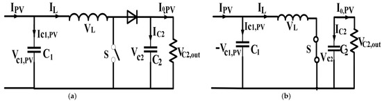
Figure 1.
Flow of IL sequence. (a) Interval when S is open. (b) Interval when S is closed.
The switch is turned on and off during one cycle; applying KCL at C1 and C2 and KVL at the inductor. This is followed by applying capacitor charge balance and volt second balance to determine at steady state. Steady-state conditions in CCM, as shown in Figure 1a,b, result in the following:
In the SMC of the boost converter, a double-integral SMC is used for tracking the maximum power point (MPP). In this method, the integral of the voltage error is taken twice. Thus, tracking performance is improved and steady-state error (SSE) is significantly minimized. This results in the reduction in chattering phenomena of SMC, and the response time of the system is improved. For tracking MPP, a feedback loop is employed by double-integral SMC for calculating the output current and voltage of the solar system. These calculations were used to find the Pout of the solar system. Next, a comparison between this calculated power and MPP was performed. At this point, the control signal of SMC for the power converter was adjusted according to Pout and MPP. A signum function was used in the control signal as a switching function, which is actually responsible for continuous control action. In SMC, the output power of the converter was controlled by regulating the control signal of its switches. Using SMC, it is possible to deal efficiently with internal and external disturbances, as well as parametric uncertainties. The sliding surface is designed so that the MPP of the DC sources should be tracked. Next, the thickness of the boundary layer was carefully selected and a double-integral SMC was designed for the regulation of the control signal to obtain optimal execution. Let x1, x2, x3, and x4 be tracking errors of the sliding surface. In such systems, the sliding surface is defined in Equation (4), in [30,31]:
Equation (5) is obtained by taking the first derivative of Equation (4):
The double-integral SMC shows robustness against uncertainties of non-parameters and parameters, in addition to a significant reduction in steady-state errors [32].
The first derivative of tracking errors in above equation gives:
Similarly, for such systems, the following can be written:
Now, Equation (8) is obtained by comparing Equations (5) and (7):
By noting the values of differentials of tracked errors in Equation (8) and then replacing them with values of and from Equations (1) and (3), the result is given by:
After rearranging:
The “D” represents the control signal of the SMC for the boost converter of the PV system. The values of the small positive number ϕ, coefficients of the required sliding sur-face represented by a1, a2, a3, and a4, and the boundary layer’s thickness, denoted by α, are given in Table 1. These parameters play a vital role in tracking maximum power using SMC.

Table 1.
Parameters of the SMC of the boost converter.
2.2. Step-Down Operational Phase for the Converter of Battery System
Initially, KCL was applied at the input capacitor (CBR) and output capacitor (CdCR), and KVL was applied at the inductor, after which capacitor-charge balance and volt second balance were applied on the obtained equations, to derive the state equations of the converter. Under steady-state conditions in CCM, Equations (11)–(13) were obtained, as shown in Figure 2a,b:
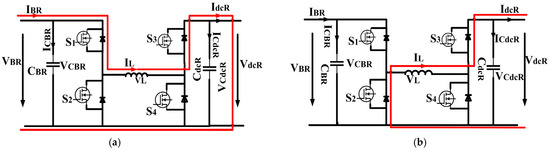
Figure 2.
Flow of IL Sequence during step-down operation of FSSB converter of battery system. (a) Interval (0-D)T. (b) Interval (1-D)T.
In this battery system, the tracking errors x1, x2, x3, and x4 are defined as follows:
By taking differentials of tracking errors, the following expression is obtained:
Next, noting the values of differentials of tracking errors in Equation (8), followed by placing the values of in the resulting equation, finally yields Equation (16) for the control signal of the SMC of this stage:
The important parameters of the SMC of buck stage of battery-side FSBB converter are listed in Table 2.
Table 2.
Parameters of the SMC of the buck stage of converter.
2.3. Boost Reverse-Operational Phase for the Converter of the Battery System
The next step is to derive the control signal’s value for the power converter’s boost reverse stage. During this process, CdcR represents the capacitor of the input side, and CBR is the capacitor of the output side. The state equations for this phase of operation at steady-state in CCM are derived, and rearranging them results in Equations (17)–(19):
The direction of the current flow during this phase is revealed in Figure 3a,b. In this battery system, tracking errors x1, x2, x3, and x4 for the boost-reverse mode are classified as follows:
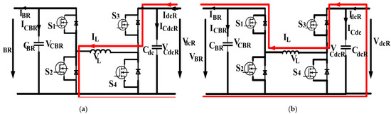
Figure 3.
Flow of IL sequence during reverse step-up operation of FSSB converter for battery system. (a) Interval (0-D)T. (b) Interval (1-D)T.
Taking derivatives of tracking errors results in (21).
After entering the values of differentials of tracked errors in Equation (8):
Noting the values of from Equations (18) and (19) in Equation (22) and, after rearranging, Equation (23) is obtained for the control signal of SMC for the reverse operation of the boost converter for charging the battery system.
The parameters of the control signal of boost-reverse stage of the battery side FSBB converter are provided in Table 3.
Table 3.
Parameters of the SMC of the Boost-Reverse Stage of Converter.
2.4. Control Signal of Buck Mode for the Load-Side Converter
When the PWM signal generates a duty cycle during the buck stage, S1 is turned on, and S2 is complementary to S1. The S3 is always on, and S4 is always off. The currents of the input side, input capacitor, inductor, load-side capacitor, and output are denoted by IB, ICB, IL, ICdc, and Idc, respectively. Similarly, the voltages across the input capacitor, inductor, and load capacitor are represented by VCB, VL, and VCdc. The input and output current and voltages are IB, Idc, VB, and Vdc, respectively. Let us assume the switching pattern of the proposed FSBB converter for one complete cycle, as indicated in Figure 4a,b. After performing some calculations, , and are found in a steady state, as expressed in Equations (24)–(26):
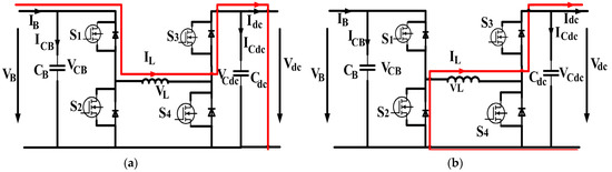
Figure 4.
Flow of IL sequence during step-down operation of FSSB converter for load system. (a) Interval (0-D)T. (b) Interval (1-D)T.
Next, it is necessary to define the tracked errors, and obtaining their first derivative results in the following:
Now, Equation (8) can be modified by noting the values of differential of tracked errors and values of and from Equations (25) and (26). After solving and readjusting the resulting equation, Equation (28) finally makes available the control signal for SMC of the proposed FSBB converter’s buck operational stage.
2.5. Control Signal of Boost Mode for the Load-Side Converter
During the step-up stage of the power converter, the S1 is always on, and S2 is always off. The S4 is turned on by the duty signal generated from PWM; S3 is complementary to the S4. The flow of IL is shown in Figure 5a,b.
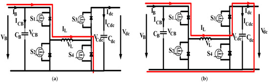
Figure 5.
Flow of IL sequence during step-up operation of FSSB converter for load system. (a) Interval (0-D)T. (b) Interval (1-D)T.
Furthermore, in the buck-converter stage, the KCL was initially applied on both capacitors and KVL on the inductor of the power converter for the total switching period. After this procedure, we applied capacitor-charge balance on capacitors and volt second balance on the inductor to observe the converter’s behavior under steady-state conditions and to obtain resulting equations for . Next, we defined the tracking errors and obtained their derivatives. Consequently, Equation (8) can be finally transformed into Equation (30):
After noting the values of and , the resulting equation was then rearranged and solved, and we found the equation of the control signal of SMC of the step-up operating phase of the proposed converter by using Equation (30):
In addition to the above discussion of control signals for different operating modes of converters, it is necessary to analyze the stability of the overall system. The stability of the system is maintained by the equation given below:
After modeling the converters for DC MGs applications, this section provides the simulation results of the SMC for the proposed converter with a faster dynamic response. It is essential to keep in mind that Equation (31) gives a definite negative value because the value of K is always very large, positive, and definite. This confirms that provision of control signal for SMC ensures that tracked error approaches zero within a definite time. It was proved in [33] that a relatively large value of “K” helps to obtain stability.
3. Simulation Results and Discussion
The overall schematic of the system in MATLAB Simulink is shown in Figure 6.
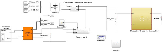
Figure 6.
Simulink model of converters for DC MG application.
The components of the boost converter of the PV system are given in Table 4.
Table 4.
Parameters of the converters.
Converter 2 is the FSBB converter, and its parameters and their values are given in Table 5.
Table 5.
Parameters of the battery-side converter.
The components of the load-side FSBB converter used in MATLAB Simulink are listed in Table 6. In addition to this, in this section, the simulation results of the power converters applied in the DC MG are analyzed and discussed.
Table 6.
Parameters of load-side converter.
3.1. Analysis of PV-Side Converter
The boost converter can be used to extract power from the PV system. This PV system consists of a solar panel, a boost converter, and a sliding mode controller. This PV can provide a maximum power of 168.5 W. Its open-circuit voltage and its voltage at its maximum power point are 43.5 V and 35 V, respectively. The output side of this boost converter is then connected to a DC link. When the switch is open, energy is stored in the inductor during this interval. Similarly, when the switch is closed, the energy stored in the inductor is discharged towards the output side of the boost converter.
The DC link in the system is also connected to a battery system and a load system. It is necessary to track the maximum voltage of the PV panel; the VPV is the input voltage, and it is necessary to obtain 35 V from this PV. Next, it is necessary to find errors between these two values and compensate for them by using SMC, by obtaining a control signal from the PWM generator. Since there are varying irradiances in the different intervals of time, there are also fluctuations in voltages and current. However, it is the role of the SMC to provide maximum voltages despite the variations in irradiances. The waveform of the PV voltage at MPPT is shown in Figure 7.
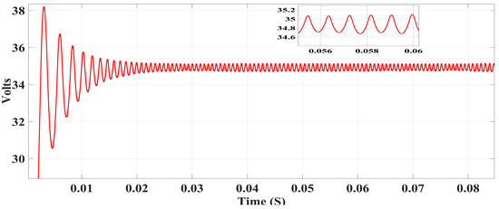
Figure 7.
Voltage at maximum power point.
The current at the maximum power point was taken as 4.71 A, with varying values of irradiance, as shown in Figure 8.
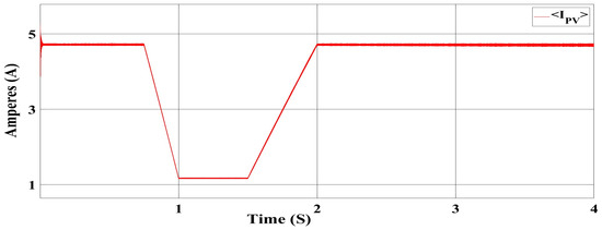
Figure 8.
Current at maximum power point.
When the irradiance value decreased, the power delivered from the PV system also decreased, and vice versa. This PV system can provide a maximum power of 168.5 W. The maximum power that can be delivered to this PV system is shown in Figure 9.
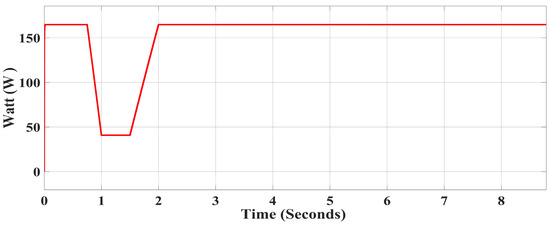
Figure 9.
Maximum power of PV panel.
3.2. Analysis of Battery Converter
In MATLAB Simulink, a lithium-ion battery was considered. The nominal voltage of the battery was taken as 80 V. The initial state of the charge was 50%. The battery had a maximum capacity of 50 Ah, and the cut-off voltage was taken as 50 V. If there was any failure in the output of the boost converter of the PV system, then the battery was expected to provide extra voltage to support the total level of 48 V for the DC bus. Since the mean voltage of the DC bus was assumed to be stabilized at 48 V, its waveform is shown in Figure 10. Another stage in the boost reverse was introduced to support the charging of the battery so that, subsequently, due to varying meteorological conditions, if the PV system could not provide voltages for the load, the battery could take over this function.
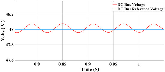
Figure 10.
DC bus voltage of DC microgrid.
3.3. Results from Load-Side Converter
Since the PV system and the battery system were connected in parallel, the mean value of the DC bus voltage was maintained at 48 V. Subsequently, this voltage was increased to 75 V. The DC bus voltage was also reduced to 25 V at the load side using the FSBB-power-converter topology to observe the converter’s robustness and dynamic response. It is clear from Figure 11 that the sliding-mode-controller-based FSBB converter showed smooth transitions between the boost and buck modes. Since the sliding surface of the SMC was accurately designed and the coefficients of the sliding surface were optimally tuned, the controller of the power converter was able to shift the mode in a smooth and robust way, along with minimizing the overshooting and undershooting of the output voltage. Thus, the controller of the proposed converter successfully achieved the required control performance while sustaining an excellent transient response, as shown in Figure 11.
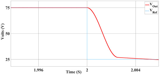
Figure 11.
Mode transition during the operation of the FSBB converter.
Detailed images of the results, when the voltage was increased from 48 V to 75 V, are shown in Figure 12. In addition, Figure 12 shows that the output voltage was uniform when using the SMC-based mechanism in the FSBB converters.
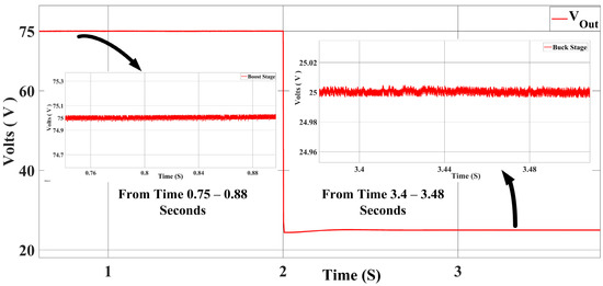
Figure 12.
Output voltage during the operation of FSBB converter.
The signal statistics within MATLAB Simulink showed that the maximum value of the voltages observed in Figure 12 was 75.08 V, and that the minimum value was 74.83 V during the boost operational stage of the power converter at the load side from the beginning of the operation to its end. Therefore, the peak-to-peak ripple voltage during this interval was 0.25 V, which is a negligible ripple value; thus, the converter ensures smooth pulsating DC voltages at the output. In Figure 12, very small intervals in both operating modes are also shown to demonstrate the ripple voltage, which confirms that the ripple voltage was quite negligible during the step-up operation and the step-down operation. Moreover, it can be observed that the controller’s response was also swift during the mode transitions.
After observing the 75 V output, another scenario was implemented for reducing the voltage to 25 V at the converter’s output to observe the system’s stability and robustness in the buck stage of the FSBB power converter on the load side. The magnified waveform of the voltages at the output during the buck-converter stage is shown in Figure 12.
According to the MATLAB Simulink’s signal statistics, the Vout was also quite smooth during the buck-converter stage. The converter operation achieved excellent stability and showed a quick dynamic response. We observed that during the boost stage, the Vout was 75 V and that the output current was 3 A, so the theoretical output power (Pout) was 225 W. Similarly, the Vout and load current (Iout) during the buck operation were 25 V and 1 A, respectively. Therefore, the Pout during the step-down stage was 25 W. The Iout transitions during both stages of the converter are also shown in Figure 13.
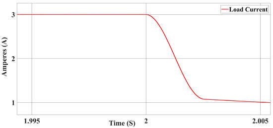
Figure 13.
Output-current transition during converter’s operation.
The output-power transition of these two stages is shown in Figure 14.
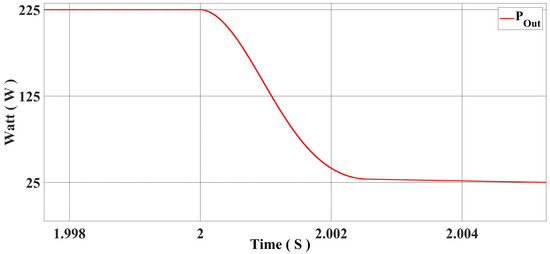
Figure 14.
Output-power transition during converter’s operation.
In addition to the results discussed above, the sliding-mode controller of the load side converter operated well and showed robust and similar behavior in the voltage range between 5 V and 75 V. It is important to mention that for the load-side converter, the DC bus voltage (48 V) was considered as the input voltage, and the results of the load-side converter are summarized in Table 7. The results in Table 7 confirm that the system can operate well in a wide range of voltage fluctuations, shows robust and swift behavior, and is completely suitable for low-power appliances.
Table 7.
Summary of results of load-side converter.
Table 8 summarizes the comparative analysis of a few research articles, as well as the challenges and limitations associated with the proposed methodology.
Table 8.
Performance analysis.
4. Conclusions
In this study, the modeling of converters for DC MG applications was performed in CCM. Next, the SMC mechanism was implemented for the step-up converter for the PV system. Subsequently, this mechanism was extended using the FSBB-converter topology for the battery and load systems. The PV system provides a maximum of 35 V and has a parallel connection to the battery system. This PV system can also be used to charge the battery system. The mean value of the DC bus voltage was maintained at 48 V. It is possible to increase the DC bus voltage to 75 V, and it can also be stepped down up to 5 V on the output side using an FSBB converter on the load side. The MATLAB Simulink results confirm that the SMC-based FSBB converter shows robustness and a quick dynamic response during mode shifting. The waveforms on the output side are quite stable and smooth during different operating modes with a wide range of voltages. In the future, a synchronous bidirectional FSBB power converter could be designed and controlled to handle bidirectional power flow for low-power applications.
Author Contributions
Conceptualization, Q.U., M.G.S., and T.D.C.B., methodology, Q.U., and T.D.C.B., Validation, Q.U., T.D.C.B., Formal analysis, Q.U., M.G.S., and T.D.C.B., Writing—original draft, Q.U., Supervision, M.G.S., T.D.C.B., and D.I.B., Project administration, Q.U., M.G.S., T.D.C.B., and D.I.B., Funding acquisition, Q.U., and M.G.S. All authors have read and agreed to the published version of the manuscript.
Funding
The APC was funded in part by Pró-Reitoria de Pesquisa (PRPq) da Universidade Federal de Minas Gerais, and in part by Research Support Foundation of the State of Minas Gerais–FAPEMIG (Grant PPM-00587-18).
Data Availability Statement
Not applicable.
Conflicts of Interest
The authors declare no conflict of interest.
References
- Anuraag, B.V.; Mahalakshmi, R.; Likhtih, S.; Bhargavi, P.; Mohanty, A. Design and Comparative Study of DC-DC Quadratic Buck-Boost Converter and Cascaded Buck-Boost Converter. In Proceedings of the 2021 International Conference on Recent Trends on Electronics, Information, Communication & Technology (RTEICT), Bangalore, India, 27–28 August 2021; pp. 642–646. [Google Scholar]
- Masood, B.; Saleem, U.; Nadeem Anjum, M.; Arshad, U. Faults Detection and Diagnosis of Transmission Lines Using Wavelet Transformed Based Technique. In Proceedings of the 2017 IEEE Jordan Conference on Applied Electrical Engineering and Computing Technologies, AEECT 2017, Amman, Jordan, 11–13 October 2017. [Google Scholar]
- Eto, J.H.; Lasseter, R.; Klapp, D.; Khalsa, A.; Baktiono, S.; Schenkman, B.; Illindala, M. The CERTS Microgrid Concept, as Demonstrated at the CERTS/AEP Microgrid Test Bed Authors and Contributors; U.S. Department of Energy’s Office of Electricity: Washington, DC, USA, 2018.
- Zhao, Z.; Yang, P.; Bottrell, N.; Lai, L.L.; Green, T.C. Dynamic Modeling, Sensitivity Assessment, and Design of VSC-Based Microgrids with Composite Loads. J. Power Electron. 2020, 20, 245–259. [Google Scholar] [CrossRef]
- Liu, C.; Zhu, D.; Zhang, J.; Liu, H.; Cai, G. A Bidirectional Dual Buck-Boost Voltage Balancer with Direct Coupling Based on a Burst-Mode Control Scheme for Low-Voltage Bipolar-Type DC Microgrids. J. Power Electron. 2015, 15, 1609–1618. [Google Scholar] [CrossRef]
- Lin, C.C.; Yang, L.S.; Wu, G.W. Study of a Non-Isolated Bidirectional DC-DC Converter. IET Power Electron. 2013, 6, 30–37. [Google Scholar] [CrossRef]
- Chen, G.; Lee, Y.S.; Hui, S.Y.R.; Xu, D.; Wang, Y. Actively Clamped Bidirectional Flyback Converter. IEEE Trans. Ind. Electron. 2000, 47, 770–779. [Google Scholar] [CrossRef]
- Li, H.; Peng, F.Z.; Lawler, J.S. A Natural ZVS Medium-Power Bidirectional DC-DC Converter with Minimum Number of Devices. IEEE Trans. Ind. Appl. 2003, 39, 525–535. [Google Scholar] [CrossRef]
- Lin, B.R.; Huang, C.L.; Lee, Y.E. Asymmetrical Pulse-Width Modulation Bidirectional DC-DC Converter. IET Power Electron. 2008, 1, 336–347. [Google Scholar] [CrossRef]
- Mi, C.; Bai, H.; Wang, C.; Gargies, S. Operation, Design and Control of Dual H-Bridge-Based Isolated Bidirectional DC-DC Converter. IET Power Electron. 2008, 1, 507–517. [Google Scholar] [CrossRef]
- Naayagi, R.T.; Forsyth, A.J.; Shuttleworth, R. High-Power Bidirectional DC-DC Converter for Aerospace Applications. IEEE Trans. Power Electron. 2012, 27, 4366–4379. [Google Scholar] [CrossRef]
- Khan, F.H.; Tolbert, L.M.; Webb, W.E. Hybrid Electric Vehicle Power Management Solutions Based on Isolated and Nonisolated Configurations of Multilevel Modular Capacitor-Clamped Converter. IEEE Trans. Ind. Electron. 2009, 56, 3079–3095. [Google Scholar] [CrossRef]
- Ko, Y.P.; Lee, Y.S.; Chao, W.H. Analysis, Design and Implementation of Fuzzy Logic Controlled Quasi-Resonant Zero-Current Switching Switched-Capacitor Bidirectional Converter. IET Power Electron. 2011, 4, 683–692. [Google Scholar] [CrossRef]
- Kim, I.D.; Paeng, S.H.; Ahn, J.W.; Nho, E.C.; Ko, J.S. New Bidirectional ZVS PWM Sepic/Zeta DC-DC Converter. In Proceedings of the IEEE International Symposium on Industrial Electronics, Vigo, Spain, 4–7 June 2007. [Google Scholar]
- Jose, P.; Mohan, N. A Novel ZVS Bidirectional Ćuk Converter for Dual Voltage Systems in Automobiles. In Proceedings of the IECON’03. 29th Annual Conference of the IEEE Industrial Electronics Society, Roanoke, VA, USA, 3–6 November 2003. [Google Scholar]
- Wai, R.J.; Duan, R.Y. High-Efficiency Bidirectional Converter for Power Sources with Great Voltage Diversity. IEEE Trans. Power Electron. 2007, 22, 1986–1996. [Google Scholar] [CrossRef]
- Wu, T.F.; Yang, J.G.; Kuo, C.L.; Kuo, M.C. Optimal Negative Current Control for Four-Phase Interleaved Bi-Directional Buck/Boost Converters to Achieve ZVS and ZCS. In Proceedings of the IEEE Applied Power Electronics Conference and Exposition—APEC 2014, Fort Worth, TX, USA, 16–20 March 2014; pp. 2017–2022. [Google Scholar] [CrossRef]
- Ning, J.; Zeng, J.; Du, X. A Four-Port Bidirectional DC-DC Converter for Renewable Energy-Battery-DC Microgrid System. In Proceedings of the 2019 IEEE Energy Conversion Congress and Exposition, ECCE 2019, Baltimore, MD, USA, 29 September–3 October 2019. [Google Scholar]
- Zeng, J.; Du, X.; Yang, Z. A Multiport Bidirectional DC-DC Converter for Hybrid Renewable Energy System Integration. IEEE Trans. Power Electron. 2021, 36, 12281–12291. [Google Scholar] [CrossRef]
- Zubieta, L.E.; Lehn, P.W. A High Efficiency Unidirectional DC/DC Converter for Integrating Distributed Resources into DC Microgrids. In Proceedings of the 2015 IEEE 1st International Conference on Direct Current Microgrids, ICDCM 2015, Atlanta, GA, USA, 7–10 June 2015. [Google Scholar]
- Fusheng, Z.; Naayagi, R.T. Power Converters for DC Microgrids—Modelling and Simulation. In Proceedings of the International Conference on Innovative Smart Grid Technologies, ISGT Asia 2018, Singapore, 22–25 May 2018. [Google Scholar]
- Sim, J.; Lee, J.; Choi, H.; Jung, J.H. High Power Density Bidirectional Three-Port DC-DC Converter for Battery Applications in DC Microgrids. In Proceedings of the 2019 10th International Conference on Power Electronics and ECCE Asia (ICPE 2019—ECCE Asia), Busan, Republic of Korea, 27–30 May 2019. [Google Scholar]
- Sarvi, M.; Soltani, I.; NamazyPour, N.; Rabbani, N. A New Sliding Mode Controller for DC/DC Converters in Photovoltaic Systems. J. Energy 2013, 2013, 871025. [Google Scholar] [CrossRef]
- Bianconi, E.; Calvente, J.; Giral, R.; Mamarelis, E.; Petrone, G.; Ramos-Paja, C.A.; Spagnuolo, G.; Vitelli, M. Perturb and Observe MPPT Algorithm with a Current Controller Based on the Sliding Mode. Int. J. Electr. Power Energy Syst. 2013, 44, 346–356. [Google Scholar] [CrossRef]
- Ullah, Q.; Wu, X.; Saleem, U. Current Controlled Robust Four-Switch Buck-Boost DC-DC Converter. In Proceedings of the 2021 International Conference on Computing, Electronic and Electrical Engineering (ICE Cube), Quetta, Pakistan, 26–27 October 2021; pp. 1–6. [Google Scholar] [CrossRef]
- Cong, W.; Jain, P. A Quantitative Comparison and Evaluation of 48V DC and 380V DC Distribution Systems for Datacenters. In Proceedings of the 2014 IEEE 36th International Telecommunications Energy Conference (INTELEC) 2014, Vancouver, Canada, 28 September–2 October 2014. [Google Scholar] [CrossRef]
- Wu, L.; Kihinet, W.; Robelo, E.; Bezabih, E.; Longwood, K.; Tshimanga, T.; Saeedifard, M.; Lambert, F.; Harley, R. Development of a Solar-Power-Based Nanogrid System for Village Huts in Haiti Mountain Area; Development of a Solar-Power-Based Nanogrid System for Village Huts in Haiti Mountain Area. In Proceedings of the 2016 North American Power Symposium (NAPS) 2016, Denver, CO, USA, 18–20 September 2016. [Google Scholar] [CrossRef]
- Khan, H.S.; Mohamed, I.S.; Kauhaniemi, K.; Liu, L. Artificial Neural Network-Based Voltage Control of DC/DC Converter for DC Microgrid Applications. In Proceedings of the 2021 6th IEEE Workshop on the Electronic Grid (eGRID), New Orelans, LA, USA, 8–10 November 2021. [Google Scholar]
- Hu, Y.; Chen, H.; Xu, R.; Li, R.; Fang, Z. A Type of High Step-up DC-DC Converter. Diangong Jishu Xuebao Trans. China Electrotech. Soc. 2012, 27, 224–230. [Google Scholar] [CrossRef]
- Chen, Z.X.; Wang, J.; Ge, L.S.; Jiang, T.; Liu, Y.F.; Liu, Y.F. Double Integral Sliding Mode Control of Paralleled DC/DC Converters. In Proceedings of the 2015 10th IEEE Conference on Industrial Electronics and Applications, ICIEA 2015, Auckland, New Zealand, 15–17 June 2015; pp. 1134–1138. [Google Scholar] [CrossRef]
- Safari, A.; Ardi, H. Sliding Mode Control of a Bidirectional Buck/Boost DC-DC Converter with Constant Switching Frequency. Iran. J. Electr. Electron. Eng. 2018, 14, 69. [Google Scholar]
- Chatrenour, N.; Razmi, H.; Doagou-Mojarrad, H. Improved Double Integral Sliding Mode MPPT Controller Based Parameter Estimation for a Stand-Alone Photovoltaic System. Energy Convers. Manag. 2017, 139, 97–109. [Google Scholar] [CrossRef]
- Pradhan, R.; Subudhi, B. Double integral sliding mode MPPT control of a photovoltaic system. IEEE Trans. Contr. Syst. Technol. 2016, 24, 285–292. [Google Scholar] [CrossRef]
- Zehelein, M.; Ruthardt, J.; Nitzsche, M.; Tymosch, T.; Roth-Stielow, J. Leakage current reduction for a double-leg boost converter by switching transition synchronization. J. Eng. 2019, 2019, 3789–3792. [Google Scholar] [CrossRef]
- Mahery, H.M.; Babaei, E. Mathematical modeling of buck-boost dc-dc converter and investigation of converter elements on transient and steady state responses. Int. J. Electr. Power Energy Syst. 2013, 44, 949–963. [Google Scholar] [CrossRef]
- Li, X.; Liu, Y.; Xue, Y. Four-Switch Buck-Boost Converter Based on Model Predictive Control with Smooth Mode Transition Capability. IEEE Trans. Ind. Electron. 2020, 68, 9058–9069. [Google Scholar] [CrossRef]


Disclaimer/Publisher’s Note: The statements, opinions and data contained in all publications are solely those of the individual author(s) and contributor(s) and not of MDPI and/or the editor(s). MDPI and/or the editor(s) disclaim responsibility for any injury to people or property resulting from any ideas, methods, instructions or products referred to in the content. |
© 2023 by the authors. Licensee MDPI, Basel, Switzerland. This article is an open access article distributed under the terms and conditions of the Creative Commons Attribution (CC BY) license (https://creativecommons.org/licenses/by/4.0/).