Article

Impact of Stearic Acid as Heat Storage Material on Energy Efficiency and Economic Feasibility of a Vacuum Tube Solar Water Heater

1
School of Mechanical Engineering, Shri Mata Vaishno Devi University, Katra 182320, India
2
Institute of Power Engineering, Universiti Tenaga Nasional, Kajang 43000, Malaysia
3
School of Energy Management, Shri Mata Vaishno Devi University, Katra 182320, India
4
Research Centre for Nano-Materials and Energy Technology (RCNMET), School of Engineering and Technology, Sunway University, Kuala Lumpur 46150, Malaysia
5
Center for Transdisciplinary Research (CFTR), Saveetha Institute of Medical and Technical Sciences, Saveetha University, Chennai 600077, India
6
Department of Electrical and Electronics Engineering, College of Engineering, Universiti Tenaga Nasional, Kajang 43000, Malaysia
7
Department of Metallurgical and Material Engineering, Karadeniz Technical University, Trabzon 61080, Turkey
8
Interdisciplinary Research Center of Renewable Energy and Power Systems (IRC-REPS), King Fahd University of Petroleum and Minerals, Dhahran 31261, Saudi Arabia
*
Author to whom correspondence should be addressed.
Energies 2023, 16(11), 4291; https://doi.org/10.3390/en16114291
Submission received: 30 March 2023 / Revised: 3 May 2023 / Accepted: 17 May 2023 / Published: 24 May 2023
(This article belongs to the Special Issue Thermal Energy Storage and Energy Conversion Technologies)

Abstract

:
The overheating of heat pipes, poor transfer of heat across the absorber and finned heat pipes, and inability to provide hot water in the late evening hours are major problems associated with conventional heat pipe vacuum collector systems. The amalgamation of highly conductive storage material between the absorber tube (heat collecting surface) and the heat pipe is an effective way to overcome these problems. In this study, a stearic acid amalgamated vacuum tube solar collector system was designed and fabricated and its thermal output compared with a conventional vacuum tube system without storage material under the same environmental conditions. The experimental results showed that the amalgamation of stearic acid as storage material enhanced the thermal output of the solar system compared to the conventional one. The desired heat gain of the solar system with storage material increased by 31.30, 23.34, and 18.78% for Test 1_40 °C, Test 2_45 °C, and Test 3_50 °C, respectively. The technoeconomic analysis showed that almost 118.80 USD in revenue could be earned by the proposed solar system at the end of 15 years. The total running cost of ELG and the developed solar system was observed to be 202.62 and 86.70 USD, respectively. On average, the cost of hot water production using the solar system and ELG was found to be 0.0016 and 0.004 USD/L, respectively. The value of LEC was found to be 0.062 USD/electricity unit, which was much lower than the LEC value of ELG (0.116 USD/electricity unit). The value of NPW (73.73 USD) indicated high acceptability of the proposed system. The payback time is lower than the life of the system, indicating its suitability for use in the commercial sector. Therefore, the proposed solar system is highly recommended over conventional water heating systems in urban and rural areas.

1. Introduction

Due to global warming and changes in the ecosystem due to the increasing use of fossil fuels, it is necessary to shift to more efficient renewable energy systems. Among the nonconventional energy sources, solar energy is the best candidate due to its free cost and abundant availability. The adoption of solar energy for the production of useful energy can save millions of tons of carbon dioxide emissions into the atmosphere every year [1]. In the USA and European Union, approximately 18 and 14% of total energy, respectively, is required to complete domestic hot water demand for bathing, cooking, cleaning, etc. [2]. A report by the Indian New and Renewable Ministry (IMNRE) showed that hot water demand in the domestic sector in India is exponentially increasing, from 129 million/day in 2017 to double that amount in 2022 [3]. This large demand for hot water is fulfilled using electricity or fossil fuels. Due to vacuum insulation, low heat losses, low initial/maintenance cost, high thermal efficiency, and highly selective coating, vacuum tube solar collectors have become popular compared to other options available for solar water heating. Vacuum tube collectors are extensively used in the industrial and residential sectors due to these peculiar features.
Vacuum tube collectors are categorized into three categories based on their design: U-tube, heat pipe, and thermosiphon. Among these designs, the heat pipe is one of the most advanced and efficient due to comparatively low heat losses, low thermal stratification, high heat dissipation, etc. The performance of this type of collector can be further enhanced by modifying its design, such as making changes to the heat pipe working fluid and integrating heat storage material. The integration of storage material in a heat pipe system is one of the convenient and economical ways to not only enhance its performance but also supply useful heat during cloudy or non-sunny times. In this regard, Pawar et al. [4] experimentally examined the performance of a heat pipe vacuum tube water heater integrated with heat storage material entrenched with copper. They also compared the performance of the proposed collector with traditional solar water under the same environmental conditions and found that the highest energy efficiency values of the developed system and the conventional system were 85.64 and 36.91%, respectively. The authors also reported that after sunshine hours, the difference in the fin temperature between the developed system and the conventional system was 36.1 °C. Algarni et al. [5] studied the impact of the integration of nano-boosted heat storage material on the thermal output of a vacuum-tube-type solar water heater. The authors reported that the integration of 0.33 wt.% copper/storage material with a solar water heater increased its thermal output by 32%. The authors also found that a solar water heater integrated with copper/storage material could deliver hot water of 50 °C for almost 2 h longer than a conventional solar water heater. Essa et al. [6] compared the thermal output of a heat pipe solar water heater with and without helical fins. The authors observed that for 0.665 and 0.5 kg/min flow rate of water, the improvement in the energy efficiency of the system with helical fin compared to the system without helical fin was 13.6 and 15%, respectively. Olfian et al. [7] analyzed a serpentine-type vacuum tube water heater employed with heat storage material to store extra heat during the daytime. They selected three different diameters (6, 8, and 10 mm) of U-tube to transfer absorbed heat from the sun to flowing water. The authors concluded that the U-tube measuring 6 mm diameter showed the highest improvement of 13.5 and 25% in outlet temperature and liquid fraction, respectively. Li et al. [8] carried out a thermal performance and optimization analysis of a serpentine-type vacuum tube solar water heater embedded with thermal accumulating material. They observed that a high flow rate of water through the solar water heater reduced the hot water supply period. They also found that the water heater with heat storage material was able to supply hot water at 35 °C for approximately 160 min more than the system without storage. Wu et al. [9] identified the impact of specific heat capacity, density, thermal conductivity, phase change heat, and melting temperature of thermal accumulating material on the thermal output of vacuum tube water heaters. The results of the study revealed that storage material with high melting temperature was advantageous to upsurge the performance of the developed system. They also observed that a vacuum tube embedded with storage material with a density of 425 kg/m3 increased the heat collection time compared to storage material with a density of 1700 kg/m3. O’Neil and Sobhansarbandi [10] compared the performance of a heat pipe solar water heater and a U-tube solar water heater with and without storage material. The experimental results revealed that the U-tube type collector had higher thermal efficiency and hot water temperature compared to the heat pipe system. Senobar et al. [11] studied the thermal output of a vacuum tube system embedded with a heat storage medium (paraffin wax). The results showed that the heat transfer rate in the selected PCM increased 2–3 times more than pure PCM by employing copper metal foam into its structure. Bouadila et al. [12] conducted a comparative thermal analysis of three solar collector systems, in which the first one was the control collector, the second one had a re-insulated manifold, and the third one had a manifold enclosed by paraffin wax as the heat storage medium. The authors found that utilization of insulation around the manifold decreased the thermal losses from 8.18 to 6.05 W/m2 K, enhanced the energy from 41 to 66%, and enhanced the exergy from 15 to 20%. Furthermore, the energy and exergy efficiencies of the third system were observed to be higher than the second system due to the reduction of overall heat losses. Kumar et al. [13] studied the impact of the integration of nano-boosted thermal accumulating material on the thermal output of the collector. The authors found that daily exergy and energy efficiencies of the system with nano-boosted PCM enriched by 13.72 and 28.78%, respectively, in comparison to the system integrated with pure PCM. Uniyal et al. [14] reviewed modifications in the latest designs, amalgamation of phase change material, and financial assessment with various vacuum-tube-based water heaters. They also addressed the problem of pure phase change materials and suggested mixing nanoparticles with pure PCM to enhance the heat transfer rate. Raza et al. [15] determined the different solar water heater potential in seven different districts of India. They found that the area of the solar collector should be determined in such a way that it can absorb solar fraction of almost 50%. The payback time of the selected collectors was in the range of 5–15 years. The simulation results showed that the state of Gujrat in India is one of the most appropriate locations to install solar water heaters. Olczak et al. [16] compared the performance of vacuum tube and flat plate solar collectors in terms of solar energy production. They observed that the solar energy productivity of the vacuum tube collector was much higher than the flat plate collector for the same absorbing area. The authors utilized a vacuum tube collector based solar water heater in mainly colder regions as they produce stable production of thermal energy. The results of the experimental investigation revealed that the efficiency of the vacuum tube collector with and without heat storage material was 58 and 38%, respectively. Jachura and Sekret [17] performed environment effect evaluation on a vacuum tube collector system and found that a PCM amalgamated collector reduced the harmful impact on the surrounding area by 17–24% in comparison to the collector without PCM.
As can be seen from Table 1, researchers have extensively carried out research work on vacuum-tube-based water heaters and improved the thermal output of the conventional solar water heater by incorporating phase change material with vacuum tube systems of different designs. In most of the investigations, authors either used pure paraffin wax and its nano-boosted composites as heat storage material. In some studies, the authors determined the economic practicality of the system before and after the amalgamation of thermal accumulating material. However, the economic viability of stearic acid as heat storage material amalgamated novel water storage heater combined with a vacuum tube collector system has not been investigated.
An economic assessment of the proposed solar collector system recommended its commercial and domestic utility in society. It was noted that almost 118.8 USD in revenue could be earned by the proposed solar system at the end of 15 years. On average, the cost of hot water production and LEC with the proposed solar system was found to be much less than ELG. Furthermore, the payback time was lower than the life of the system, making it suitable for use in the commercial and domestic sectors.
In addition to this, the proposed system reduced the issue of overheating in thermosiphon heat pipes, and its performance was enhanced by the incorporation of conductive stearic acid as the thermal energy storage material. This modified collector was also compared to the conventional system. The energy efficiency of the proposed solar water heater improved by 18–31% compared to the heat pipe system without storage.

2. Description of Experimental Setup and Methodology

The developed setup units were tested in the outside environment of Jammu and Kashmir, India. To judge the impact of heat storage material on the thermal output of the vacuum tube solar collector system, a conventional collector was also tested in parallel with a developed solar collector under the same environmental conditions. In this study, a solar collector (VTSC-I) was embedded with stearic acid as storage material, while a tube was left without storage material (VTSC-II).
As shown in Figure 1, in both systems (VTSC-I and VTSC-II), the hot water loaded tank was integrated with a heat pipe vacuum tube system to diminish the overall heat loss from the system. The water storage tank for both VTSC-I and VTSC-II could store up to 3.5 L of water. The experiment was conducted for three consecutive days for different temperature limits of hot water (40, 45, and 50 °C). During the first day, the highest limit of water in the header was set as 40 °C. On this day, water was allowed to heat from its initial temperature until it reached 40 °C, then drained out and stored in a tank for further usage. At the end of the day, the calculation was carried out according to the total collected hot water of 40 °C. The same methodology was adopted for temperature limits of 45 and 50 °C.
As shown in Figure 2, the temperature sensors T1, T2, and T3 for VTSC-I were located at the bottommost, middle, and topmost portions of the insulated water tank. On the other hand, T4, T5, and T6 for VTSC-II were located at the bottommost, middle, and topmost portions of the insulated water tank. The temperature of the heat storage material filled inside the tube of VTSC-I was measured by T7 and T8, while the temperature of the internal air of vacuum tubes of VTSC-II was measured by T9 and T10. The temperature of the outside air was determined by T11. The properties of stearic acid embedded with a vacuum tube collector are given in Table 2. Table 3 presents the description of the specification of the experimental setup.

3. Heat Transfer and Economic Analysis

This section provides the heat transfer and economic analysis of the design system and its comparison with an electrical heating system.

3.1. Heat Transfer Analysis

In the vacuum tube collector system, the incident solar insolation was gathered by the VTSC (vacuum tube solar collector) and transformed into heat energy by the absorber tube. After that, the heat energy collected by the absorber tube was transferred to phase change material or internal air for the systems with and without storage, respectively. Then, heat was conveyed to the finned heat pipe. Finally, heat was transferred to water flowing in the manifold through heat pipes. The incident energy gathered by the inner absorber of the tube was fragmented into two portions. The primary portion of the gathered heat was conveyed to the surrounding area as heat loss, while the other portion of collected thermal energy was conveyed to water in the puffed insulated manifold through a heat pipe.
To compare the thermal output of the developed and conventional solar collector systems under the same environment, the useful energy collected by each collector was calculated as follows [22]:
Q uf = ρ wf ×   V ˙ wf × C P , wf × ( T wf , o T wf , in )
where ρ wf (kg/m3) is the working fluid density;   V ˙ wf (m3/s) is the working fluid flow rate; C P , wf (kJ/kgK) is the working fluid specific heat; T wf , o (°C) is the working fluid outlet temperature; and T wf , in (°C) is the working fluid inlet temperature.
For evaluation of the energy efficiency of the individual collector (developed or conventional solar collector system), incident solar radiation was determined by the following relation [22]:
Q in = G T × A cr × Δ τ
where G T (W/m2) is the instantaneous solar insolation, and A cr (m2) is the area of the collector.
The daily energy performance ( η EP ) of the solar water heating structure can be determined by the following equation [23]:
η EP = ρ wf C P , wf A cr   V ˙ wf × ( T wf , o T wf , in ) G T

3.2. Economic Viability Analysis

In the present study, along with heat transfer analysis, economic feasibility and financial benefits of the developed collector compared to a conventional solar water heater and an electric water heater were also studied. This analysis is advantageous in terms of the practical deployment of the project in the residential and commercial sectors.
As per the literature survey, three important factors help to assess the financial benefits and economic feasibility of any business model: levelized energy price (LEP), net present worth (NEPW), and payback time (PT). These three economic factors can be evaluated through the following relations.
The levelized energy price for solar water heater can be calculated by taking a proportion of the annual uniform charge from the produced hot water in the same year [24]:
LEP N = YU N AHP N
where YU N ($) is the uniform cost of the system for the Nth year, and AHP N (L) is the hot water production for the Nth year.
The uniform cost of the solar water heater includes yearly bank installments against debt for the installation of the system, maintenance and operation cost, and auxiliary energy cost during non-sunny days [24]
YU N = YI N + MO N + AE N
where YI N ($) is the yearly installment for the Nth year; MO N ($) is the maintenance and operation cost for the Nth year; and AE N ($) is the auxiliary energy cost for the Nth year.
According to [25],
YI N = C I × DE r × ( 1 N Life + ( N Life N N Life ) × it r )
where C I ($) is the capital investment in the system; DE r (%) is the debt/equity ratio; N Life (year) is the life of the system; and it r (%) is the bank interest rate.
AE N = ( ER   [ ( N s × G T × A cr × Δ τ × η th ) × ( 1 d r ) N ] ) × EP N
where ER (kWh/year) is the energy required;   N s (days/year) is the number of clear sunny days per year;   d r (%) is the degradation rate of the performance of the collector; and EP N ($/kWh) is the electricity price for the Nth year.
The net present worth (NEPW) provides the total income made by the installation of the business project. It is a very crucial factor whose value decides the viability of the installed project. The project is not acceptable if the NPEW is negative, otherwise, the project can be accepted [25].
NEPW = C I + N = 0 N CFL N ( 1 + DE r ) N
where CFL N ($) is the cash flow for the Nth year.
Another important factor of the financial analysis is the payback time, which is beneficial for assessing the associated risk of initial capital investment of a project. This parameter indicates how much of the time invested in the system can be recovered [26].
PB T = N = 0 N CFL N C I

4. Results and Discussion

This section presents and discusses a complete analysis of the different experimental outcomes. Measurable data are used to compare the energy efficiency and performance improvement ratio of a manifold cum water storage tank integrated single evacuated tube water heater with and without heat storage material. The subsections of this section are devoted to addressing the variation of input and output variables: solar radiation, water inlet, energy analysis, outlet temperature, and a useful amount of heat acquired by working fluid under different test situations and economic viability.

4.1. Disparity in Outside Air Temperature and Solar Energy for Different Test Days

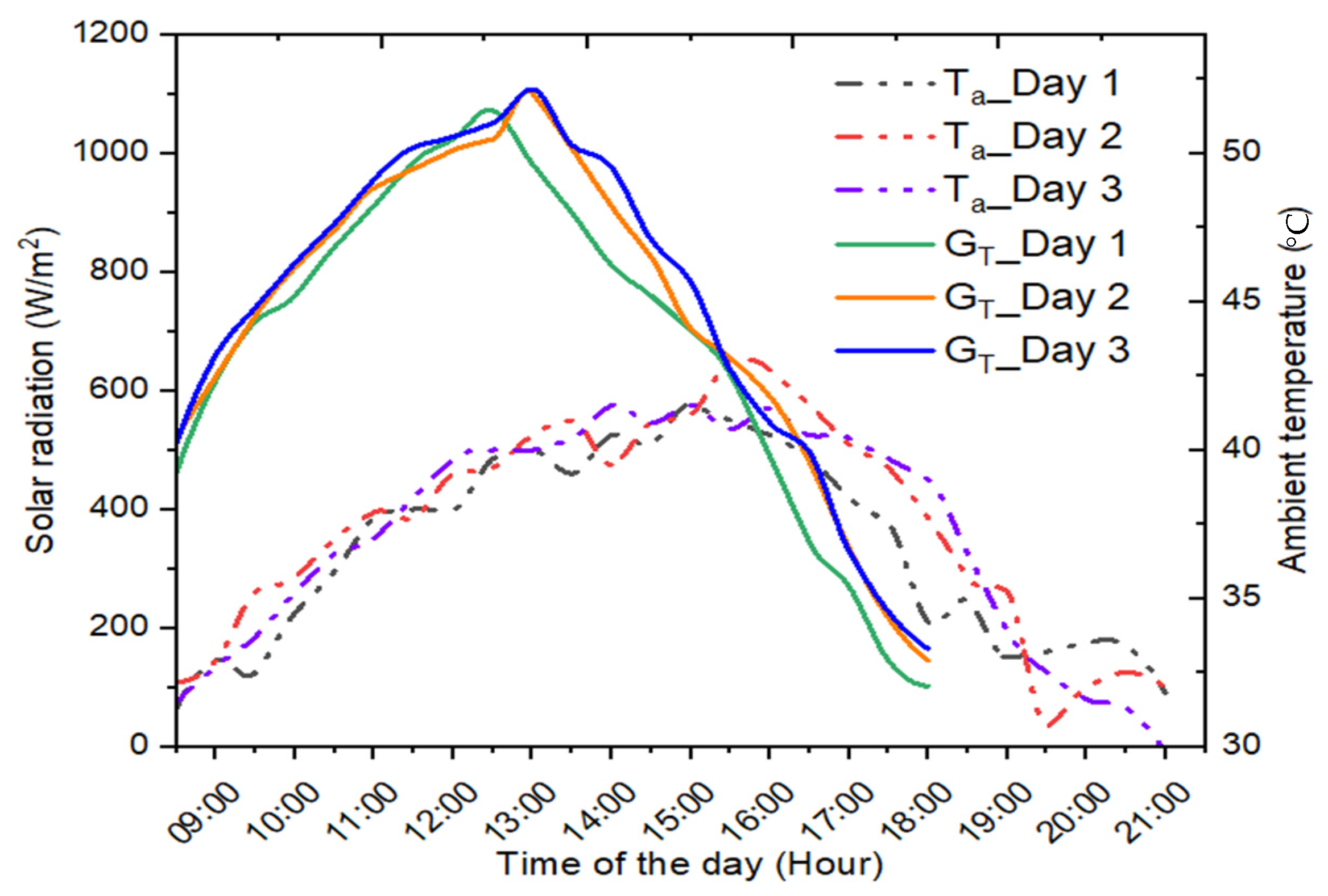
Figure 2 depicts the disparity in outside air temperature and solar energy with respect to time for different test days. Each test was conducted in its unique setting. It can be observed from the figure that changes in solar radiation were relatively consistent between different test days. However, the intensity of solar radiation varied marginally on each of the three days, with the most variance occurring in the evening hours. According to the data, which were collected with the help of a solarimeter, solar radiation was at its highest in the morning and at its lowest in the afternoon. The investigations were conducted during periods of clear, bright weather conditions in April 2022.
The average daily maximum solar radiation was 1072 W/m2 on day 1 (Test 1_50 °C), 1101 W/m2 on day 2 (Test 2_45 °C), and 1108 W/m2 on day 3 (Test 3_40 °C). As an additional note, the average daily solar radiation incident on the collector area was 24.34 MJ/m2 on day 1, 26.03 MJ/m2 on day 2, and 26.61 MJ/m2 on day 3. Figure 2 also shows the variation in ambient temperature with respect to time for all three test days. The average ambient temperature was 36.71, 37.41, and 37.16 °C for days 1, 2, and 3 respectively. It can be seen that the highest value of ambient temperature for all tests surpassed 40–43 °C in the afternoon. The temperature variation shows the composite dry environmental conditions in which the experiment was performed.

4.2. Disparity in Hot Water Temperature of Control and Testing Systems

In the present investigation, the integrated header for both the control (reference) system (without thermal accumulating material) and the testing system (embedded with storage material) was built to be able to store 3.5 L of water. For Test 1_50 °C, the freshwater was assimilated inside the integrated storage tank of the vacuum tube system and heated until it reached 50 °C. Then, it was emptied and gathered in an insulated tank so that it could be used for domestic applications. A similar procedure was carried out for water temperatures of 45 °C (Test 2_45 °C) and 40 °C (Test 3_40 °C).
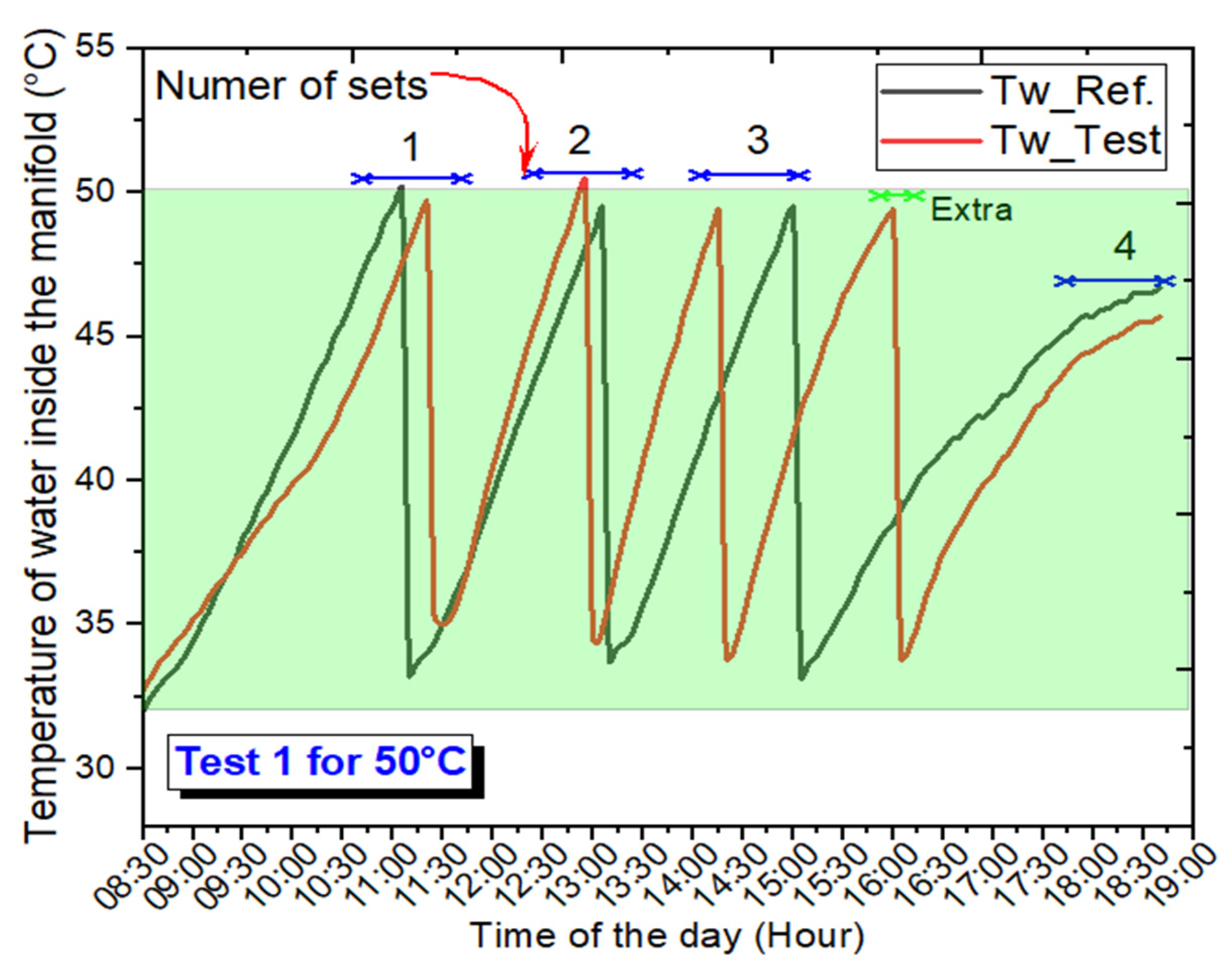
Figure 3, Figure 4 and Figure 5 show the tank water temperature variations for the control and testing systems for Test 1_50 °C, Test 2_45 °C, and Test 3_40 °C, respectively. During each experiment, the freshwater in the 31–32 °C temperature range was filled in the tank (header). From Figure 3, it can be observed that there were four refills (14 L) for the reference system and five refills (17.5 L) for Test 1_50 °C. Due to the utilization of highly effective heat storage material (stearic acid), the testing system yielded a higher amount of heat compared to the reference system (without PCM).
The integration of PCM has several advantages, one of which is that it accumulates an excessive input thermal energy in the form of latent thermal energy in the course of its phase change and then discharges that heat in the late evening hours. Because the testing system employed phase change material, it could operate during the late evening hours when solar radiation was no longer available.
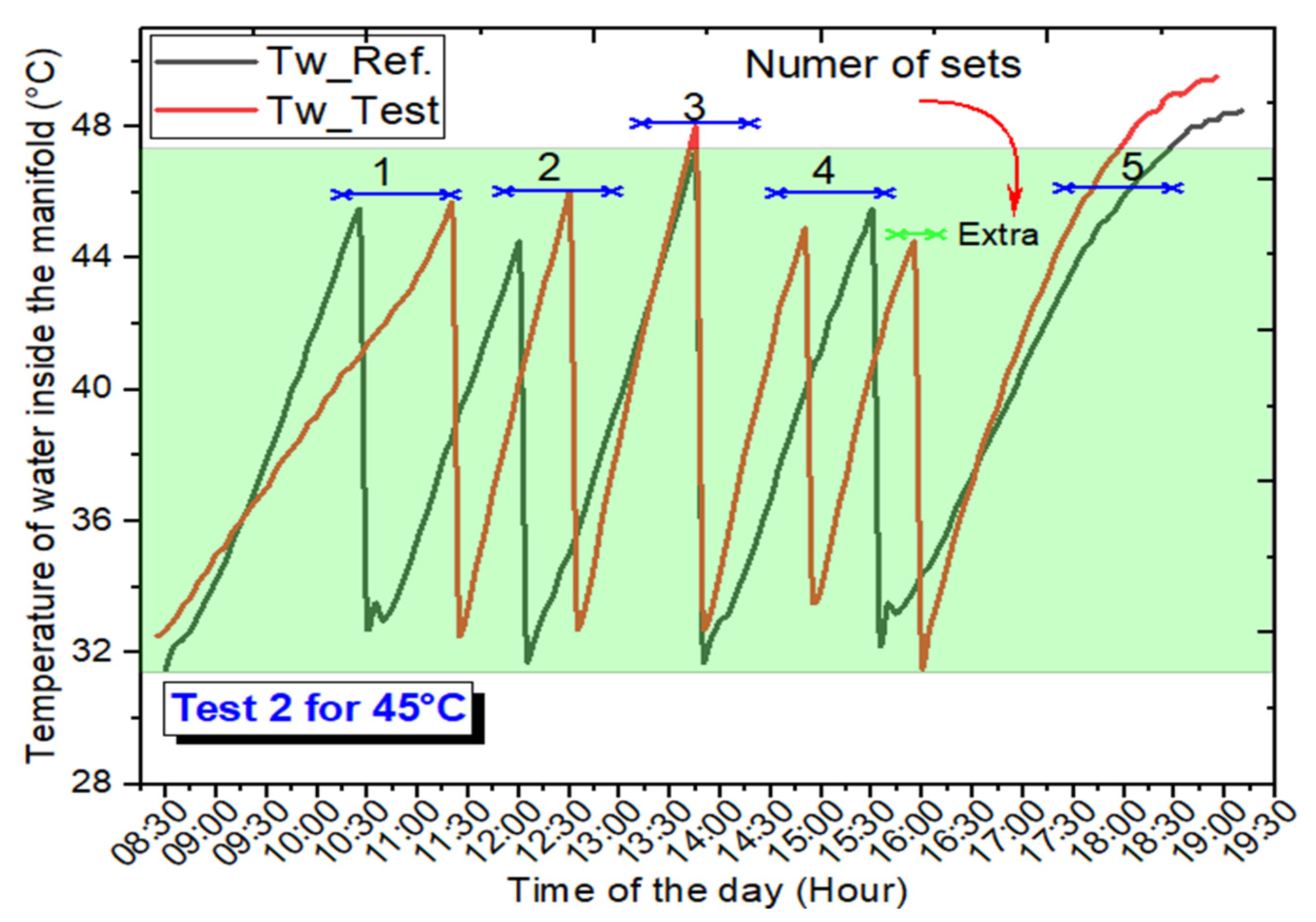
As shown in Figure 3 and Figure 4 for both the reference and test systems, the variation in hot water temperature during Test 2_45 °C was similar to Test 1_50 °C. The freshwater (used for refill) temperature range was determined to be between 29 and 32.5 °C. Both the reference and test systems were found to be operational from 8:30 to 19:30. For Test 2_45 °C, the water was changed five times in the control system and six times in the developed testing system. The total amount of hot water (at 45 °C) provided by the control system was 17.5 L, whereas the amount of hot water provided by the developed testing system was 21 L.
The stored water temperature variations in the manifolds of the reference and test systems for Test 3_40 °C are shown in Figure 5. In both setups, the water was heated to 40 °C in a single-tube header before being drained and stored as hot water. As shown in Figure 5, the 40 °C hot water was changed nine times in the reference system and 12 times in the testing system. As per the calculation, 31.5 L of hot water was provided by the control system, whereas 42 L of water was collected from the testing system. The operation hours for the control and developed testing systems were determined to be 08:30 to 19:30. Hence, the testing system with thermal accumulating material could provide more hot water for an extended period after sunset than the control system without thermal accumulating material.

4.3. Temperature Variation in Internal Air and Heat Storage Material for Different Tests

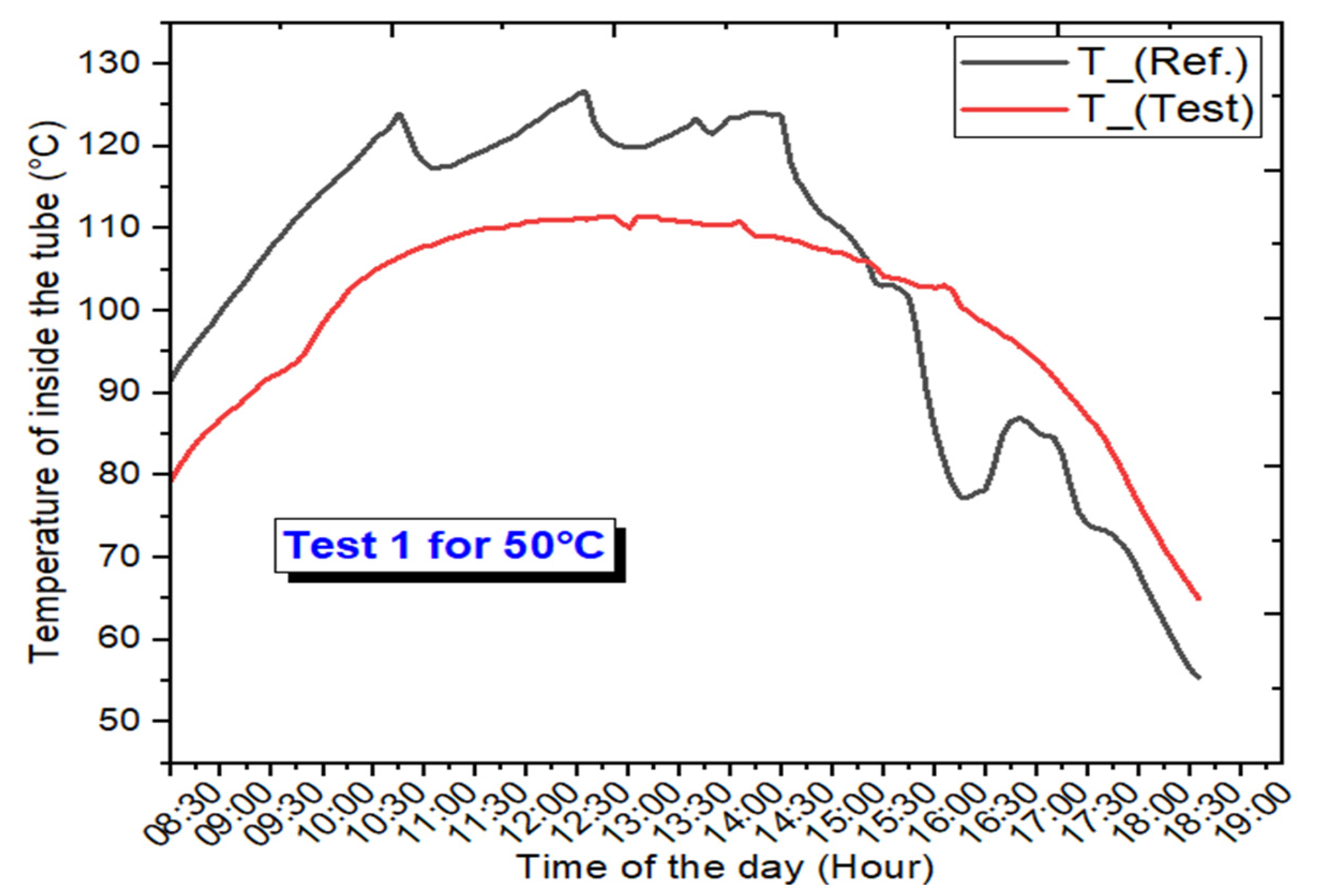
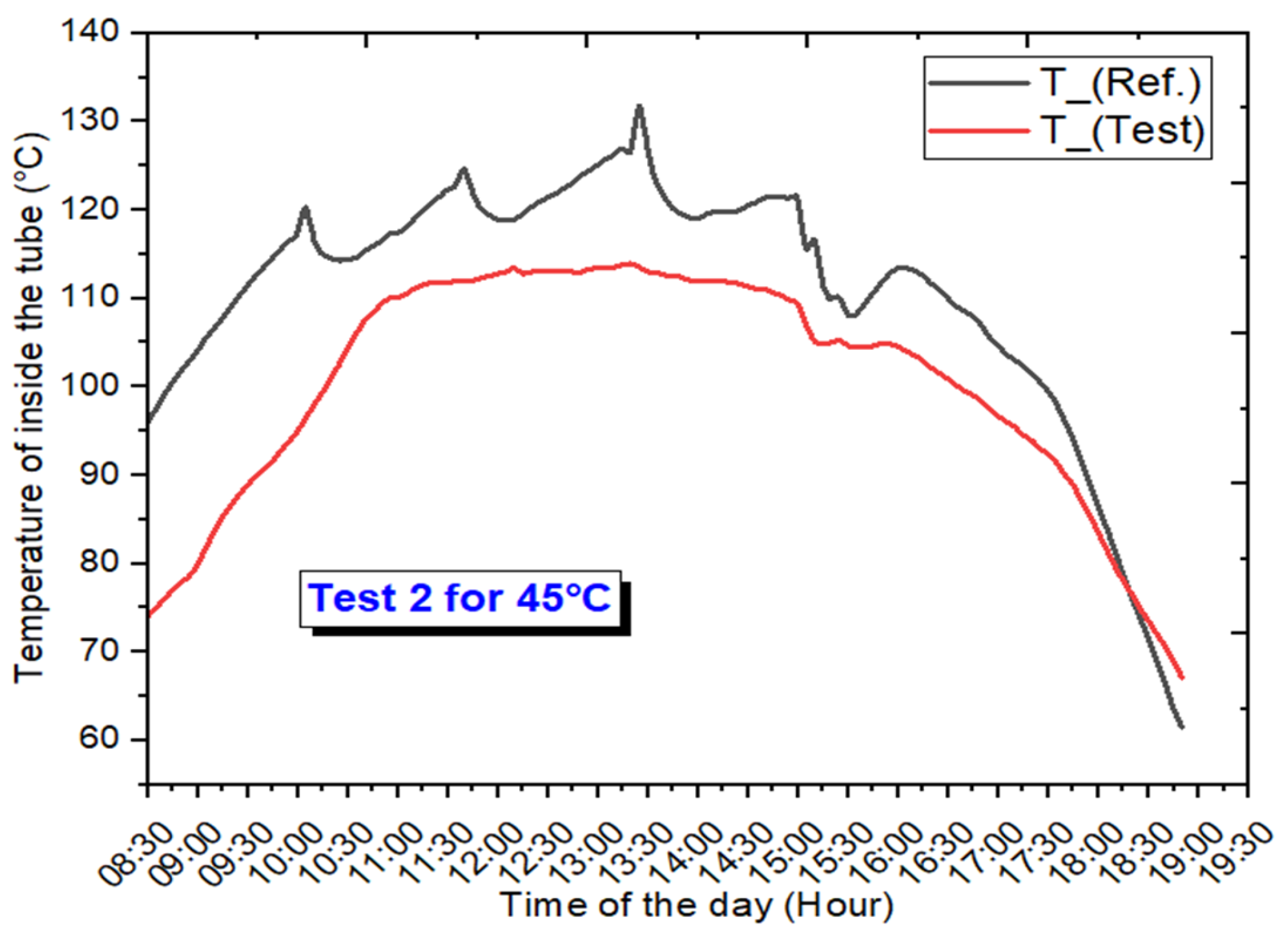
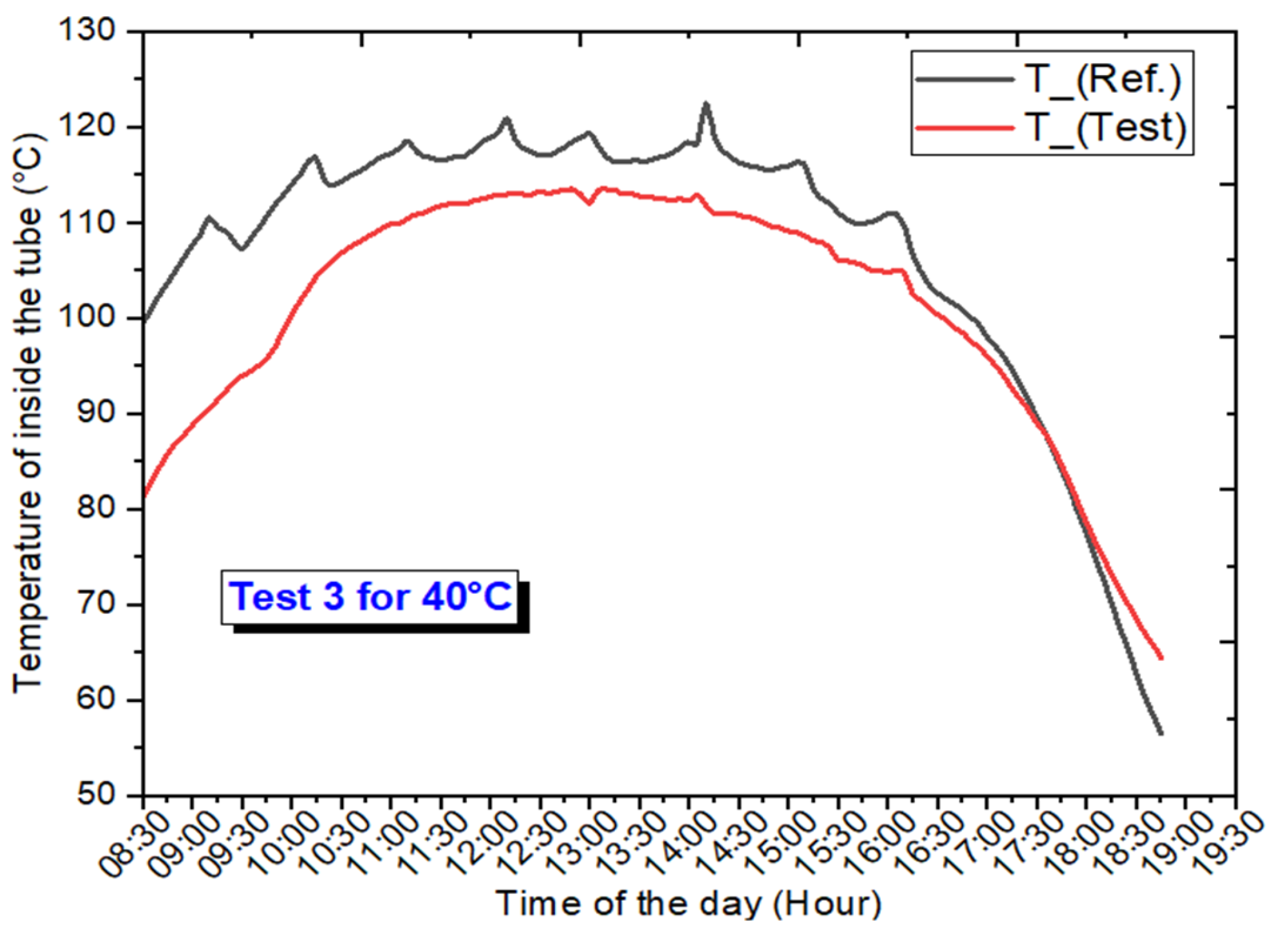
This subsection discusses the variability in temperature inside the vacuum tube of both testing and reference systems for different tests under consideration (as shown in Figure 6, Figure 7 and Figure 8). To conduct the experiment, stearic acid (the phase change substance) was poured into the testing system’s tube, while the reference system tube was left empty. It is important to keep in mind that the designated PCM started melting at about 10:00 a.m. The PCM in the lower section had completed the phase transition process and was experiencing significant temperature increases, while the PCM in the upper section was still undergoing it. It was determined that the temperature of the PCM was consistently less than the air within the vacuum tube of the control (reference) system because PCM has a higher heat requirement for phase shift.
Solar energy is accumulated within the heat storage material, and it is later transferred to the working fluid (water) when solar irradiation is weak or not available. Hence, in contrast to the situation in which PCM is absent, hysteresis takes place. The amalgamation of the thermal accumulating material with the developed testing system enables a reduction in the tube’s highest temperature during high solar radiation. Moreover, this additional heat can be used to provide hot water during non-sunny hours.

4.4. Variation of Set-Wise Useful Heat for Different Tests at 50, 45, and 40 °C

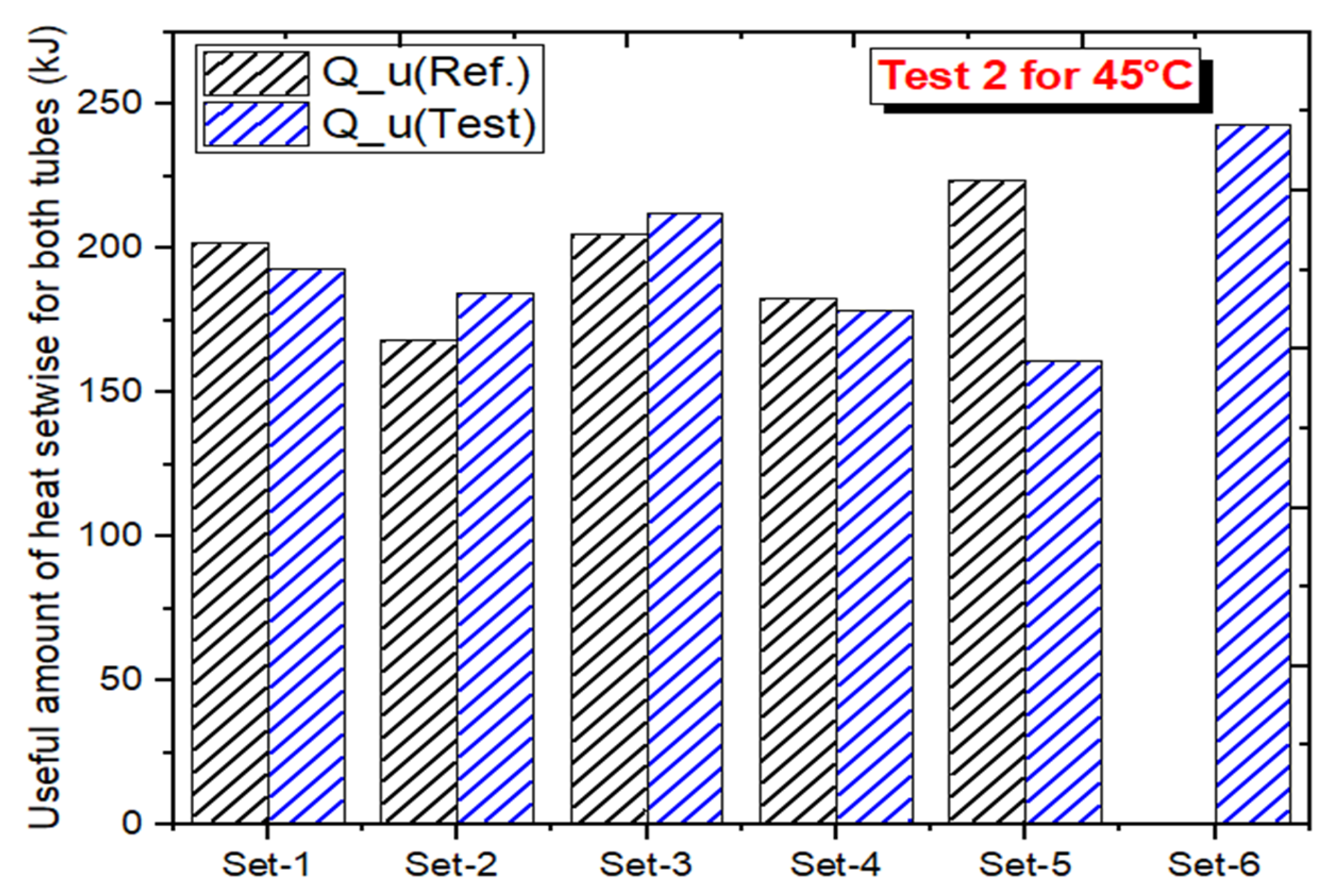
The useful amount of heat collected by the reference and testing systems for Test 1_50 °C, Test 2_45 °C, and Test 3_40 °C conditions is shown in Figure 9, Figure 10 and Figure 11.
Figure 9 shows the amount of heat collected by water in different sets for day 1 to reach the set limit of temperature (50 °C) in both systems. It was observed that four sets of 50 °C were completed by the reference system with heat gain values of 258.95, 226.76, 223.83, and 185.801 kJ. In comparison, five sets of 50 °C (water temperature limit to refill) were completed by the testing system with heat gain values of 248.71, 212.13, 217.98, 222.37, and 168.24 kJ. The quantities of heat collected by water in both systems in different sets for day 2 to achieve the desired limit of temperature (45 °C) are depicted below in Figure 10.
The findings showed that the reference system completed five sets of 45 °C with heat gain values of 201.89, 168.24, 204.82, 182.87, and 223.83 kJ, respectively, for each set. In comparison, the testing system completed six sets of 45 °C with heat gain values of 193.11, 184.33, 212.13, 178.48, 160.93, and 242.85 kJ for each set.
Similarly, Figure 11 shows the amounts of heat collected by water in both systems in different settings on day 3 to reach the target temperature limit (40 °C). The result showed that the reference system completed nine cycles (45 °C water temperature) with heat gain values of 105.33, 95.09, 90.70, 106.79, 98.02, 136.05, 109.72, 90.70, and 143.37 kJ for each cycle. In comparison, the testing system performed 12 cycles of 45 °C water temperature with heat gain values of 103.87, 131.67, 111.18, 117.04, 102.41, 98.02, 106.79, 111.18, 83.39, 112.65, 83.39, and 181.41 kJ for each cycle.

4.5. Disparity in Daily Thermal Energy Input/Output and Energy Efficiency of the Proposed Systems for Different Tests

Every thermal system’s energy efficiency depends on the quantity of absorbed/lost heat. In the current study, the testing system was embedded with heat storage material, while the reference system was without heat storage material or internal air between the absorber and finned heat pipe. The PCM possesses improved thermal properties than internal air. As a result of this, it was observed that the heat transfer rate across the blackened inner tube and the aluminum finned heat pipe was significantly higher, which resulted in a reduction in the overall heat loss and an increase in the generation of heat that can be used.
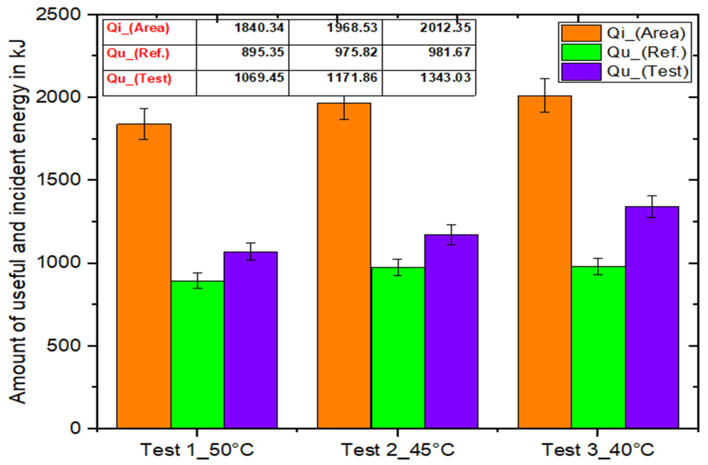
Figure 12 depicts the fluctuation in usable energy obtained by water and incident energy with error bars on the aperture area of a single evacuated tube. For Test 1_50 °C, the testing system obtained 1069.45 kJ of usable energy from water, whereas the reference system gained 895.35 kJ. Similarly, the desired thermal outputs acquired by working fluid (water) for the testing and control systems were 1171.86 and 975.82 kJ, respectively, for Test 2_45 °C and 1343.03 and 981.67 kJ, respectively, for Test 3_40 °C. The total energy incident on the aperture area of the single tube was 1840.34, 1968.53, and 2012.35 for Test 1_50 °C, Test 2_45 °C, and Test 3_40 °C, respectively.
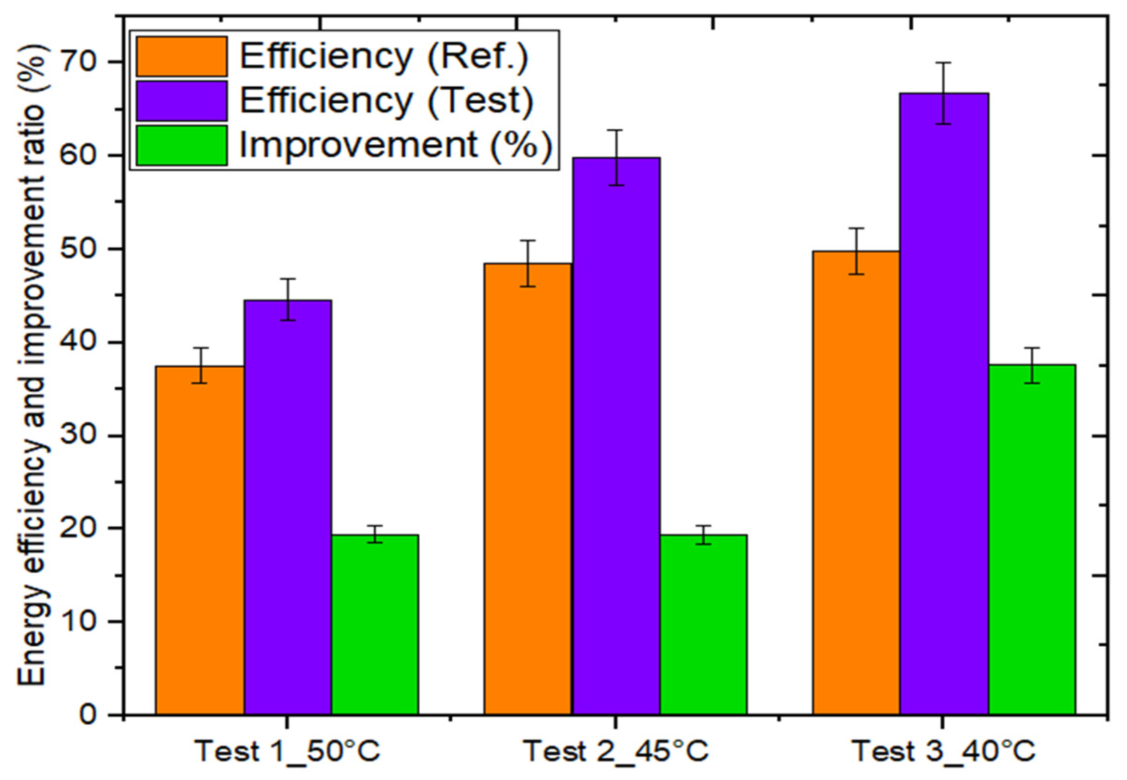
Figure 13 shows the daily thermal (energy) performance of both systems (testing and reference) for different tests. As a result of the experimental research, it was determined that the daily thermal (energy) efficiency of the developed testing system was 66.78, 59.82, and 44.58% for Test 1_40 °C, Test 2_45 °C, and Test 3_50 °C, respectively. In contrast to this, the daily energy efficiency of the control (reference) system was 50.86, 48.50, and 37.53% for Test 1_40 °C, Test 2_45 °C, and Test 3_50 °C, respectively. The ratio of augmentation in the testing system’s daily thermal efficiency was determined to be 31.30, 23.34, and 18.78% for Test 1_40 °C, Test 2_45 °C, and Test 3_50 °C, respectively. Thus, it could be concluded that the utilization of thermal accumulating material in the developed testing system resulted in an improvement in the daily energy efficiency for all tests.
The main goal of any water heating system based on solar energy is to offer water of the desired temperature even during cloudy, rainy, or non-sunny hours. Often, this is possible with the installation of a collector that is bigger than necessary, thus allowing the storage of additional hot water in an insulated tank. This increases both the overall cost and the heat loss from the water container.
Hence, the utilization of heat storage material in the water heating system proposed in this study along with the provision of hot water during periods of non-sunny hours enhances the system’s output at a lower price. In contrast, commercial solar water heaters are incapable of producing hot water at these periods. Hence, the use of potential PCMs is a realistic option in solar water heaters.

4.6. Outcomes of Technoeconomic Analysis

In the present section, the economic practicality of the designed and developed vacuum collector systems is discussed and its results compared with the traditional thermal energy supplying system i.e., electric geyser (ELG). It may be noted that the economic practicality of the developed system was assessed by taking into consideration the economic factors of the local solar market of India. These economic factors are given in Table 4.
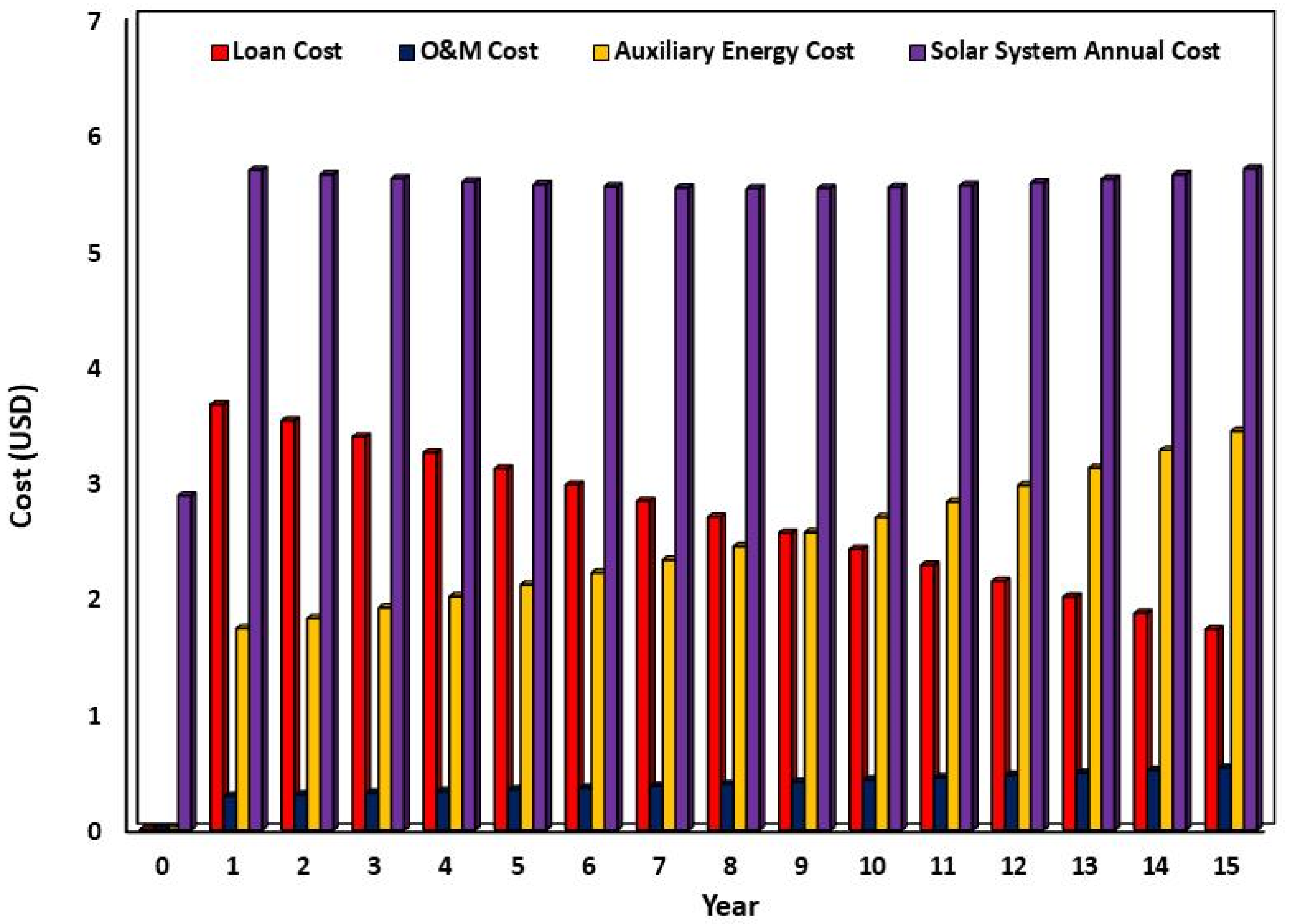
The loan cost, O&M cost, auxiliary energy cost, and gross solar system cost variation of the proposed solar collector system are depicted in Figure 14. It was found that the loan cost decreased over the years due to decreasing interest, whereas the maintenance and operational cost was found to increase due to increase in inflation. Similarly, the auxiliary energy cost was found to increase with time. This is because the auxiliary energy cost is dependent on the price of electricity, which is increasing with time. In a nutshell, gross solar system costs increased over the years due to the dominance of increasing O&M costs and auxiliary energy costs over decreasing loan costs. On average, the annual cost of a solar system was found to be 5.43 USD after 15 years of operation.
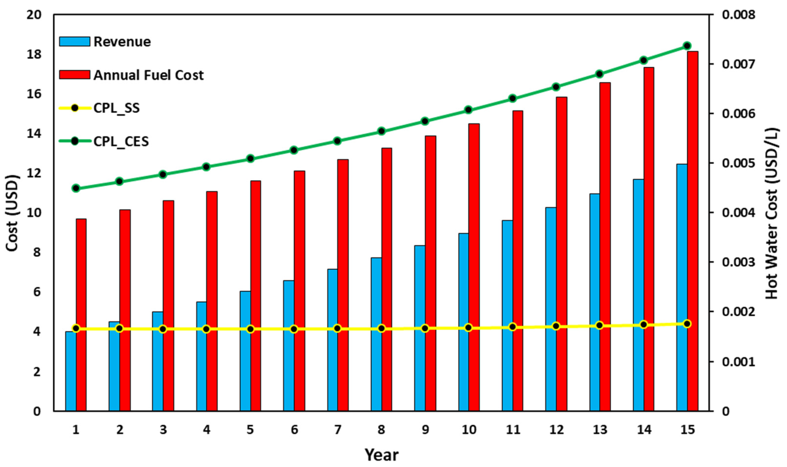
The variation of hot water generation cost by solar and ELG, the fuel cost of the ELG system, and revenue earned by a solar system with reference to ELG are depicted in Figure 15. This figure also indicates the calculated value of the levelized cost of energy, the net present worth, and the payback time of the solar system after its 15 years of operation. The revenue earned by the solar system was observed to have increased due to the continuously increasing electricity prices. It was noted that at the end of 15 years, almost 9504 INR revenue could be earned by the proposed solar system. The annual fuel cost of the traditional thermal system (ELG) exponentially increased due to the tremendous increase in electricity prices. The total running cost of ELG and the developed solar system was observed to be 202.62 and 86.70 USD, respectively.
On the other hand, the cost of hot water production using both the solar system and ELG increased with time due to the increase in electricity prices. On average, the cost of hot water production with the solar system and ELG was found to be 0.0016 and 0.004 USD/L, respectively. Therefore, the proposed solar system is highly recommended over ELG-based water heating systems in urban and rural areas.
After simulation through EES software, the three important economic factors were also evaluated to measure the economic practicality of the proposed system, i.e., levelized cost of energy (LEC), net present worth (NPW), and the payback time (PBT). The value of LEC was found to be 0.062 USD/electricity unit, which was much lower than the LEC value of ELG (0.116 USD/electricity unit). As shown in Figure 15, the value of NPW (73.73 USD) indicates the high acceptability of the proposed system. Furthermore, the payback time was less than the life of the system, making it suitable for use in the commercial sector.

5. Conclusions

The overheating of heat pipes, poor transfer of heat across the absorber and finned heat pipe, and inability to provide hot water in the late evening hours are major problems associated with conventional heat pipe vacuum collector systems. The amalgamation of highly conductive storage material between the absorber tube (heat collecting surface) and the heat pipe is an effective way to overcome these problems. In this study, a stearic acid amalgamated vacuum tube solar collector system was designed and fabricated and its thermal output compared with a conventional vacuum tube system without storage material under the same environmental conditions. The experimental results showed that the amalgamation of stearic acid as storage material enhanced the thermal output of the solar system compared to the conventional one. This study’s experimental results led to the following conclusions.
The testing system with PCM could produce hot water during late evening hours (non-sunny/night hours) and improve the collector’s thermal output.
The amount of total usable heat output produced by the testing system with PCM was 179.10, 196.04, and 361.36 kJ more than the system without storage for Test 1_50 °C, Test 2_45 °C, and 19.44% Test 3_40 °C, respectively.
The maximum energy efficiency of the two systems was 66.78 and 50.86% for Test 3_40 °C.
The improvement in the energy efficiency of the testing system was 37.67% for Test 1_50 °C, 19.37% for Test 2_45 °C, and 19.44% for Test 3_40 °C compared to the reference system.
The amount of additional hot water received from the testing system was 3.5 L for Test 1_50 °C and Test 2_45 °C and 10.5 L for Test 3_40 °C.
It was noted that at the end of 15 years, almost 118.8 USD in revenue could be earned by the proposed solar system. The total running cost of ELG and the proposed solar system was observed to be 202.62 and 86.70 USD, respectively.
On average, the cost of hot water production with the solar system and ELG was found to be 0.0016 and 0.004 USD/L, respectively. Therefore, the proposed solar system is highly recommended over conventional water heating systems in urban and rural areas.
The value of LEC was found to be 0.062 USD/electricity unit, which was much lower than the LEC value of ELG (0.116 USD/electricity unit). The value of NPW (73.73 USD) indicated high acceptability of the proposed system. Furthermore, the payback time was lower than the life of the system, making it suitable for use in the commercial sector.

Author Contributions

K.C.: writing—original draft, investigation, methodology, acquisition of data, review and editing, V.V.T.: writing, reviewing and editing, investigation, supervision, S.K.P.: methodology, writing, review and editing, A.K.: formal analysis, reviewing and editing, A.K.P.: writing—reviewing and editing, N.A.R.: formal analysis, writing—reviewing, M.M.: editing, supervision and reviewing, A.S.: methodology and formal analysis. All authors have read and agreed to the published version of the manuscript.

Funding

This work was supported by Tenaga Nasional Berhad (TNB) and UNITEN through the BOLD Refresh Postdoctoral Fellowships under the project code J510050002-IC-6 BOLDREFRESH2025-Centre of Excellence. It was also supported by Shri Mata Vaishno Devi University, Katra (J&K) through the research project with unique ID RP-141 (Japan International Cooperation Agency Project for AUN/SEED-NET and the University of Malaya Malaysia).

Data Availability Statement

Data should be made available on request.

Conflicts of Interest

The authors declare no conflict of interest.

References

  1. Zhu, T.-T.; Zhao, Y.-H.; Diao, Y.-H.; Li, F.-F.; Quan, Z.-H. Experimental investigation and performance evaluation of a vacuum tube solar air collector based on micro heat pipe arrays. J. Clean. Prod. 2017, 142, 3517–3526. [Google Scholar] [CrossRef]
  2. Fuentes, E.; Arce, L.; Salom, J. A review of domestic hot water consumption profiles for application in systems and buildings energy performance analysis. Renew. Sustain. Energy Rev. 2018, 81, 1530–1547. [Google Scholar] [CrossRef]
  3. Chopra, K.; Tyagi, V.; Pandey, A.; Sari, A. Global advancement on experimental and thermal analysis of evacuated tube collector with and without heat pipe systems and possible applications. Appl. Energy 2018, 228, 351–389. [Google Scholar] [CrossRef]
  4. Pawar, V.R.; Sobhansarbandi, S. Heat transfer enhancement of a PCM-porous metal based heat pipe evacuated tube solar collector: An experimental study. Sol. Energy 2023, 251, 106–118. [Google Scholar] [CrossRef]
  5. Algarni, S.; Mellouli, S.; Alqahtani, T.; Almutairi, K.; Khan, A.; Anqi, A. Experimental investigation of an evacuated tube solar collector incorporating nano-enhanced PCM as a thermal booster. Appl. Therm. Eng. 2020, 180, 115831. [Google Scholar] [CrossRef]
  6. Essa, M.A.; Rofaiel, I.Y.; Ahmed, M.A. Experimental and Theoretical Analysis for the Performance of Evacuated Tube Collector Integrated with Helical Finned Heat Pipes using PCM Energy Storage. Energy 2020, 206, 118166. [Google Scholar] [CrossRef]
  7. Olfian, H.; Ajarostaghi, S.S.M.; Ebrahimnataj, M.; Farhadi, M.; Arıcı, M. On the thermal performance of evacuated tube solar collector integrated with phase change material. Sustain. Energy Technol. Assess. 2022, 53, 102437. [Google Scholar] [CrossRef]
  8. Li, Y.; Liang, X.; Song, W.; Li, T.; Wang, D.; Liu, Y. Optimization and thermal performance of U-type evacuated tube solar collector filled with phase change material. Energy Rep. 2022, 8, 6126–6138. [Google Scholar] [CrossRef]
  9. Wu, Y.; Tong, X.; Li, D.; Arıcı, M.; Liu, C.; Liu, Y.; Yang, R.; Yu, Y. Energy analysis of evacuated tube solar collector integrating phase change material in northeast China. J. Energy Storage 2022, 55, 105772. [Google Scholar] [CrossRef]
  10. O’neil, T.J.; Sobhansarbandi, S. Thermal performance investigation of energy storage based U-pipe evacuated tube solar collector: An experimental study. Sustain. Energy Technol. Assess. 2022, 52, 102146. [Google Scholar] [CrossRef]
  11. Senobar, H.; Aramesh, M.; Shabani, B. Evacuated tube solar thermal collector with enhanced phase change material thermal storage: An experimental study. J. Energy Storage 2021, 46, 103838. [Google Scholar] [CrossRef]
  12. Bouadila, S.; Rehman, T.-U.; Baig, M.A.A.; Skouri, S.; Baddadi, S. Energy, Exergy and Economic (3E) analysis of evacuated tube heat pipe solar collector to promote storage energy under North African climate. Sustain. Energy Technol. Assess. 2023, 55, 102959. [Google Scholar] [CrossRef]
  13. Kumar, P.; Mylsamy, K. A comprehensive study on thermal storage characteristics of nano-CeO2 embedded phase change material and its influence on the performance of evacuated tube solar water heater. Renew. Energy 2020, 162, 662–676. [Google Scholar] [CrossRef]
  14. Uniyal, A.; Prajapati, Y.K.; Ranakoti, L.; Bhandari, P.; Singh, T.; Gangil, B.; Sharma, S.; Upadhyay, V.V.; Eldin, S.M. Recent Advancements in Evacuated Tube Solar Water Heaters: A Critical Review of the Integration of Phase Change Materials and Nanofluids with ETCs. Energies 2022, 15, 8999. [Google Scholar] [CrossRef]
  15. Raza, S.A.; Ahmad, S.S.; Ratlamwala, T.A.H.; Hussain, G.; Alkahtani, M. Techno-Economic Analysis of Glazed, Unglazed and Evacuated Tube Solar Water Heaters. Energies 2020, 13, 6261. [Google Scholar] [CrossRef]
  16. Olczak, P.; Matuszewska, D.; Zabagło, J. The Comparison of Solar Energy Gaining Effectiveness between Flat Plate Collectors and Evacuated Tube Collectors with Heat Pipe: Case Study. Energies 2020, 13, 1829. [Google Scholar] [CrossRef]
  17. Jachura, A.; Sekret, R. Life Cycle Assessment of the Use of Phase Change Material in an Evacuated Solar Tube Collector. Energies 2021, 14, 4146. [Google Scholar] [CrossRef]
  18. Essa, M.A.; Mostafa, N.H.; Ibrahim, M.M. An experimental investigation of the phase change process effects on the system performance for the evacuated tube solar collectors integrated with PCMs. Energy Convers. Manag. 2018, 177, 1–10. [Google Scholar] [CrossRef]
  19. Olfian, H.; Ajarostaghi, S.S.M.; Farhadi, M.; Ramiar, A. Melting and solidification processes of phase change material in evacuated tube solar collector with U-shaped spirally corrugated tube. Appl. Therm. Eng. 2021, 182, 116149. [Google Scholar] [CrossRef]
  20. Ali, S.H.; Eidan, A.A.; Al Sahlani, A. Study the Effect of Phase Change Material on the Performance of Evacuated Tube Heat Pipe Solar Collector under Iraqi Climatic Conditions. IOP Conf. Ser. Mater. Sci. Eng. 2021, 1094, 012009. [Google Scholar] [CrossRef]
  21. Kumar, P.M.; Mylsamy, K.; Alagar, K.; Sudhakar, K. Investigations on an evacuated tube solar water heater using hybrid-nano based organic phase change material. Int. J. Green Energy 2020, 17, 872–883. [Google Scholar] [CrossRef]
  22. Bouadila, S.; Baddadi, S.; Rehman, T.-U.; Ayed, R. Experimental investigation on the thermal appraisal of heat pipe-evacuated tube collector-based water heating system integrated with PCM. Renew. Energy 2022, 199, 382–394. [Google Scholar] [CrossRef]
  23. Chopra, K.; Tyagi, V.; Pandey, A.; Sharma, R.; Sari, A. PCM integrated glass in glass tube solar collector for low and medium temperature applications: Thermodynamic & techno-economic approach. Energy 2020, 198, 117238. [Google Scholar] [CrossRef]
  24. Chopra, K.; Tyagi, V.; Pathak, S.K.; Tripathi, P.A.; Sharma, R.; Singh, G.; Pandey, A. Thermal and chemical reliability of paraffin wax and its impact on thermal performance and economic analysis of solar water heater. Energy Sustain. Dev. 2023, 73, 39–53. [Google Scholar] [CrossRef]
  25. Chopra, K.; Tyagi, V.; Pandey, A.; Popli, S.; Singh, G.; Sharma, R.; Sari, A. Effect of simultaneous & consecutive melting/solidification of phase change material on domestic solar water heating system. Renew. Energy 2022, 188, 329–348. [Google Scholar] [CrossRef]
  26. Zheng, Y.; Hatzell, K.B. Technoeconomic analysis of solar thermal desalination. Desalination 2020, 474, 114168. [Google Scholar] [CrossRef]
  27. Chopra, K.; Tyagi, V.; Popli, S.; Pandey, A. Technical & financial feasibility assessment of heat pipe evacuated tube collector for water heating using Monte Carlo technique for buildings. Energy 2023, 267, 126338. [Google Scholar] [CrossRef]
  28. Pathak, S.K.; Tyagi, V.; Chopra, K.; Sari, A. Thermal performance and design analysis of U-tube based vacuum tube solar collectors with and without phase change material for constant hot water generation. J. Energy Storage 2023, 66, 107352. [Google Scholar] [CrossRef]
  29. Retail Domestic Term Deposits-Interest Rates, (n.d.). Available online: https://sbi.co.in/web/interest-rates/deposit-rates/retail-domestic-term-deposits (accessed on 28 April 2023).
  30. Inflation in India 2028|Statista, (n.d.). Available online: https://www.statista.com/statistics/271322/inflation-rate-in-india/ (accessed on 28 April 2023).
  31. Velayudhan, S. Dissemination of solar photovoltaics: A study on the government programme to promote solar lantern in India. Energy Policy 2003, 31, 1509–1518. [Google Scholar] [CrossRef]
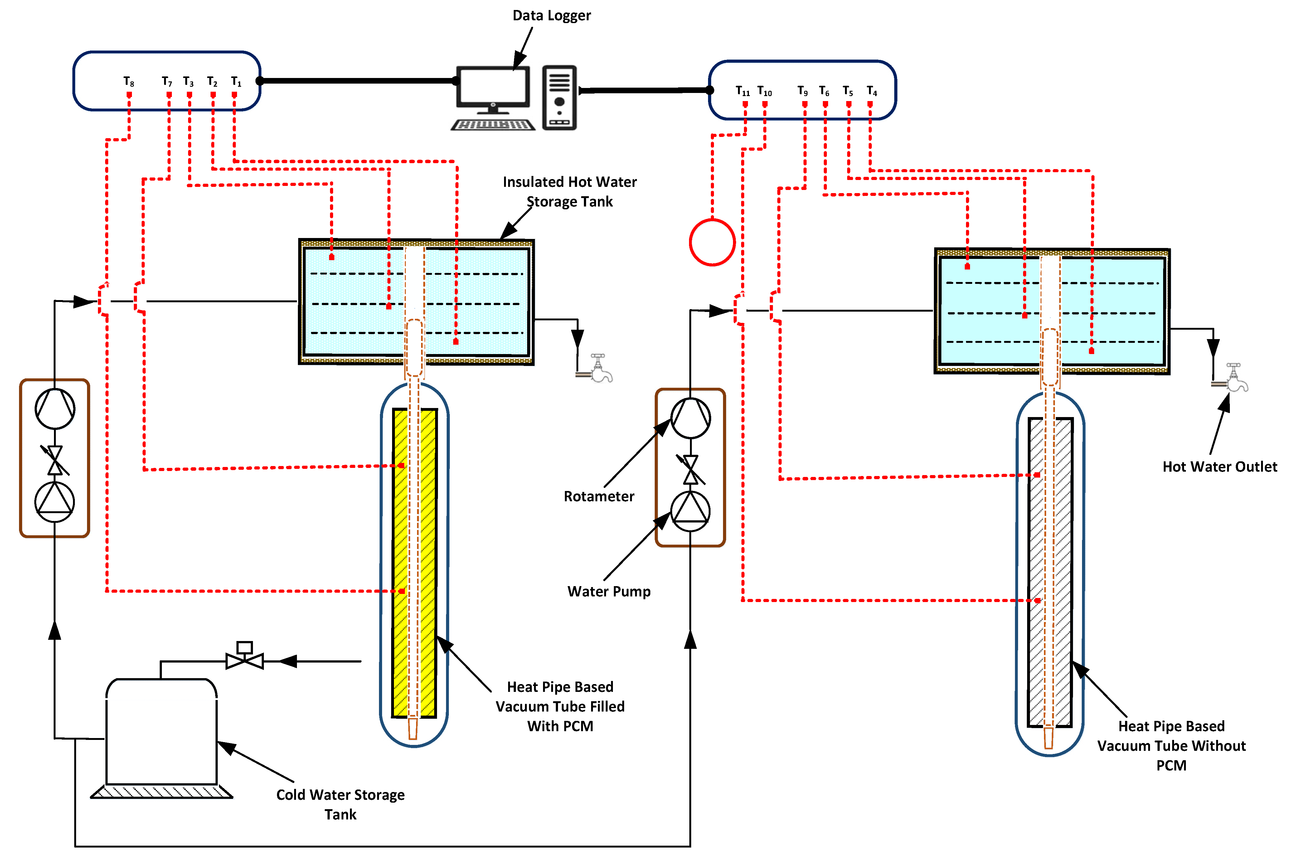
Figure 1. Schematic arrangement of the proposed vacuum tube collector systems.
Energies 16 04291 g001
Figure 2. Solar radiation and ambient temperature variation with respect to time.
Energies 16 04291 g002
Figure 3. Hot water temperature variation inside the manifold of both systems for Test 1_50 °C.
Energies 16 04291 g003
Figure 4. Hot water temperature variation inside the manifold of both systems for Test 2_45 °C.
Energies 16 04291 g004
Figure 5. Hot water temperature variation inside the manifold of both systems for Test 3_40 °C.
Energies 16 04291 g005
Figure 6. Temperature variation inside the vacuum tube of both systems for Test 1_50 °C.
Energies 16 04291 g006
Figure 7. Temperature variation inside the vacuum tube of both systems for Test 2_45 °C.
Energies 16 04291 g007
Figure 8. Temperature variation inside the vacuum tube of both systems for Test 3_40 °C.
Energies 16 04291 g008
Figure 9. Set-wise useful amount of heat collected from both systems for Test 1_50 °C.
Energies 16 04291 g009
Figure 10. Set-wise useful amount of heat collected from both systems for Test 2_45 °C.
Energies 16 04291 g010
Figure 11. Set-wise useful amount of heat collected from both systems for Test 3_40 °C.
Energies 16 04291 g011
Figure 12. Daily heat input and outputs of both systems at 50, 45, and 40 °C.
Energies 16 04291 g012
Figure 13. Daily thermal (energy) efficiency and enhancement ratio for different tests at 50, 45, and 40 °C.
Energies 16 04291 g013
Figure 14. Variation of loan cost, O&M cost, auxiliary energy cost, and gross solar system cost.
Energies 16 04291 g014
Figure 15. Variation of revenue, annual fuel cost, and cost per liter for the proposed systems.
Energies 16 04291 g015
Table 1. Comparison of the proposed study with previous studies.
Author (s)YearType of SystemParameters CalculatedIncrement in Energy Gain
Essa et al. [18]2018SerpentineEnergy and thermal output investigation 6.8–21.9%
Olfian et al. [19]2020SerpentineThermal and system efficiency measurement and impact of operation temperature13.6–15%
Kumar et al. [13]2021Heat PipeEffect of different percentages of nano-boosted PCM and first and second law analysis 3–5%
Wong et al. [20]2022Heat PipeHeat transfer and thermal efficiency investigation3–5%
Wu et al. [9]2022SerpentineImpact of PCM’s properties and thermal efficiency analysis4.31%
Kumar et al. [21]2022Water in GlassEffect of different percentages of nano-boosted PCM and energy and exergy investigation 7%
Proposed StudyExperimentalEnergy, Exergy, and Economic Analysis18–31%
Table 2. Properties of stearic acid.
PropertyValue/Specification
ColorCaramel white
Melting temperature range60–62 °C
Latent heat range185–190 J/g
Specific heat at 75 °C2.45
Density at 75 °C1.19
Purity99.8%
Table 3. Specification of the proposed systems.
ItemSpecification/Value
Number of vacuum tubes1
Aperture area of collector0.080
Diameter/length of an evaporator of heat pipe9.5/1600 mm
Diameter/length of the condenser of heat pipe14/63 mm
Material of heat pipe finAluminium
Diameter of water storage header130 mm
Length of water storage header270 mm
Insulation on water storage headerRockwool
Table 4. Economic factors of the local solar market in India.
FactorsValueUnit
Initial investment on proposed collector [27]375USD/m2 area
Maintenance and operational cost of system [27]1%
Loan interest rate [28]9%
Loan term 15years
Debt ratio90%
Price of electricity [27]0.081USD/unit
Life of system [28]15years
Rise in electricity price [27]10%/year
Discount/reinvestment rate [29]5%
Inflation rate [30]4.5%/year [27]
Rate of degradation of thermal energy0.50%/year
Average daily solar insolation based on the selected days during experiments6.76–7.39kWh/m²
Average daily energy efficiency based on experiment44–67%
Number of sunny days [31]300days/year
Disclaimer/Publisher’s Note: The statements, opinions and data contained in all publications are solely those of the individual author(s) and contributor(s) and not of MDPI and/or the editor(s). MDPI and/or the editor(s) disclaim responsibility for any injury to people or property resulting from any ideas, methods, instructions or products referred to in the content.