Article

Outlet Pressure and Flow Characteristics of a New Two-Dimensional Piston Pump with an Overlapped Distributor

Key Laboratory of Special Purpose Equipment and Advanced Manufacturing Technology, Ministry of Education & Zhejiang Province, Zhejiang University of Technology, Hangzhou 310014, China
*
Author to whom correspondence should be addressed.
Energies 2023, 16(11), 4303; https://doi.org/10.3390/en16114303
Submission received: 24 March 2023 / Revised: 17 May 2023 / Accepted: 19 May 2023 / Published: 24 May 2023

Abstract

:
This article presents the design of a two-dimensional (2D) piston pump flow-distribution port with an overlapped structure that reduces backflow in the pump chamber and pressure ripples at the pump outlet, thus minimizing vibration and noise caused by the high-frequency distribution process of a single two-dimensional (2D) piston pump. We describe the flow distribution structure and operation principle of the 2D pump, create a mathematical model of the pump chamber pressure by using the motion and flow continuity equations of the 2D piston, and use a Matlab program to compile and solve them. The influence of the flow distribution port overlap on the pump chamber pressure and the outlet flow rate was simulated. A prototype was designed and tested on a dynamic performance test bench. Our test bench results show that the flow distribution port overlap can reduce the pressure ripple at the pump outlet, which is consistent with the simulation results.

1. Introduction

In recent years, compact hydraulic drives have gained widespread usage in various applications, including aerospace, robots, and mechanical exoskeletons designed for support or operations. These drives offer several advantages over other transmission types, particularly in terms of the power–weight ratio. High power density is the most important requirement for using axial piston pumps in the aerospace industry, therefore, the power–weight ratio of the components for energy supply and delivery also needs to be further improved [1]. A pump control system that utilizes motor speed control is more efficient than the variable pump system currently in use. The compact hydraulic drive is poised to enter the era of electrification by substituting centralized drives with distributed drives. The core of a compact hydraulic system in the electrification era is the hydraulic pump, which requires a wide speed range, four quadrants of working capacity, and a higher speed [2,3,4,5,6].
In 2014, Ruan proposed a novel hydraulic pump structure with a single rotating piston [7]. The characteristic features of this structure are the four windows on the cylinder block and a piston with a symmetrical flow distribution slot fitting into the cylinder hole. Two saddle-shaped end-face guides are mounted on both sides of the cylinder block, with the highest point of one guide corresponding to the lowest point of the other. Two pairs of rollers are fixed on both sides of the piston rod, forming a piston motion component that is guided by the two guide surfaces. This allows the piston motion component to perform a rotational and reciprocating motion around its own axis. It has two degrees of freedom of motion, so it is referred to as a “two-dimensional piston pump” or “2D pump” for short. Due to the two peaks and valleys on the cam, the slots on the piston alternately communicate with the two piston chambers. As the piston rotates, the flow distribution of the pump is achieved by the piston slot and the window. The piston completes four strokes by reciprocating twice as it rotates one full circle. The symmetrical rotating structure of the 2D pump balances the radial force in the piston motion components, eliminates the sliding friction pair, and only requires a low driving torque. This makes it very suitable for use in electric hydraulic pumps [8].
Furthermore, Ruan proposed a 2D pump that features fixed rollers as constraints and cam guides installed on the piston rod [9]. To counter the effect of the inertial force of the piston motion component of the pump, two types of 2D pumps with inertia force balancing structures have been proposed [10,11,12]. Additionally, to increase the working pressure of the pump, a 2D pump with stacked rollers as driving elements has been put forward [13,14]. To reduce the flow ripple of the pump, series and parallel structures of the two pump cores have also been suggested [15,16]. Various researchers, including Jin, Shentu, and Huang, and others [17,18,19], have investigated the output characteristics, volumetric efficiency, and mechanical efficiency of 2D pumps with different structures. Their findings show that the maximum speed of a 2D pump exceeds 12,000 r/min, and at a working pressure of 20 MPa, the volumetric efficiency can reach up to 98%. These studies also examined the impact of various driving structures on pump characteristics. Ruan and Xing designed 2D piston fuel pumps with different structures and studied their output characteristics [20,21,22]. Their results show that these fuel pumps have high working speeds and volumetric efficiencies, with a volumetric efficiency of up to 91% at a working pressure of 5 MPa. Ding applied the principles of a 2D pump to design a flowmeter with a dynamic response and study its dynamic characteristics [23,24,25,26]. When the input flow frequency was 5 Hz, the measured flow curve was almost in phase with the input flow.
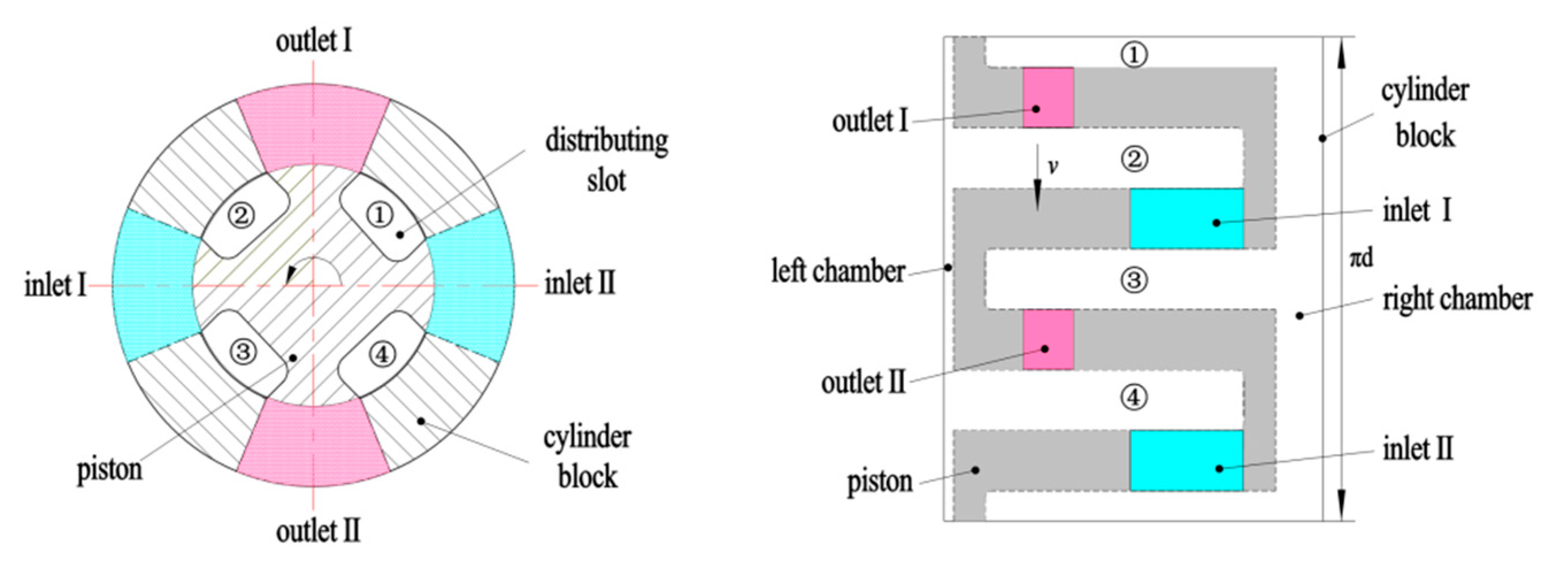
Figure 1 depicts a new type of plug-in 2D pump core structure with a high operating speed and a compact structure. The pump piston has four slots (labeled as (1)–(4) in Figure 2) arranged radially, that alternately communicate with the two side pump chambers. The cylinder block has four evenly distributed windows, forming four oil ports (two inlet and two outlet) for the hydraulic fluid, as shown in Figure 2. When the roller is at the highest (or lowest) point of the guide rail and the piston is at the extreme position of its reciprocating motion, the piston seals the distribution windows tightly with the arc segment of the piston. As the piston rotates, the distribution windows are opened, connecting the left pump chamber with the suction port and the right pump chamber with the pressure port. Simultaneously, the piston moves to the right, causing the volume of the right pump chamber to decrease and pump oil out, while the volume of the left pump chamber increases and draws in oil. This method of using the piston’s rotation to achieve distribution without additional distribution components results in a compact pump structure, which is beneficial for miniaturization.
In Figure 1, the guide rail surface follows the law of equal acceleration and deceleration. During the flow distribution through the rotating-piston slot, the instantaneous flow rate presents an approximately triangular waveform with a ripple frequency four times that of the rotational speed. The authors found in their previous study that using the piston slot distribution structure shown in Figure 2, when the suction chamber finishes suction and is ready to discharge, at the instant of connection with the outlet, there will be backflow of flow due to the significant difference between the pressure in the chamber and the outlet pressure, resulting in additional pressure ripples. This caused a marked increase in fluid noise, particularly at high speed. The pressure ripple is an important performance parameter of the pump, and an increase in its amplitude may cause resonance of the machine body, thereby increasing the instability of the pump. The stability of the aviation piston pump is the key to ensure the long endurance cruise of the aircraft under high-altitude conditions. Usually, the pressure ripple of the aviation piston pump is required to be within ±10%, while it is usually limited to within ±5% on civil aircraft [27]. Based on the previous research on the two-dimensional piston fuel pump, this paper innovatively and deeply analyzes and studies the problem of a large output pressure ripple of the 2D pump with a single-piston structure, and proposes a method to reduce pump pressure ripples by designing an overlap of the flow distribution port, and studies the instantaneous output flow and pressure characteristics of the pump.

2. Distribution Principle with an Overlapped Distributor

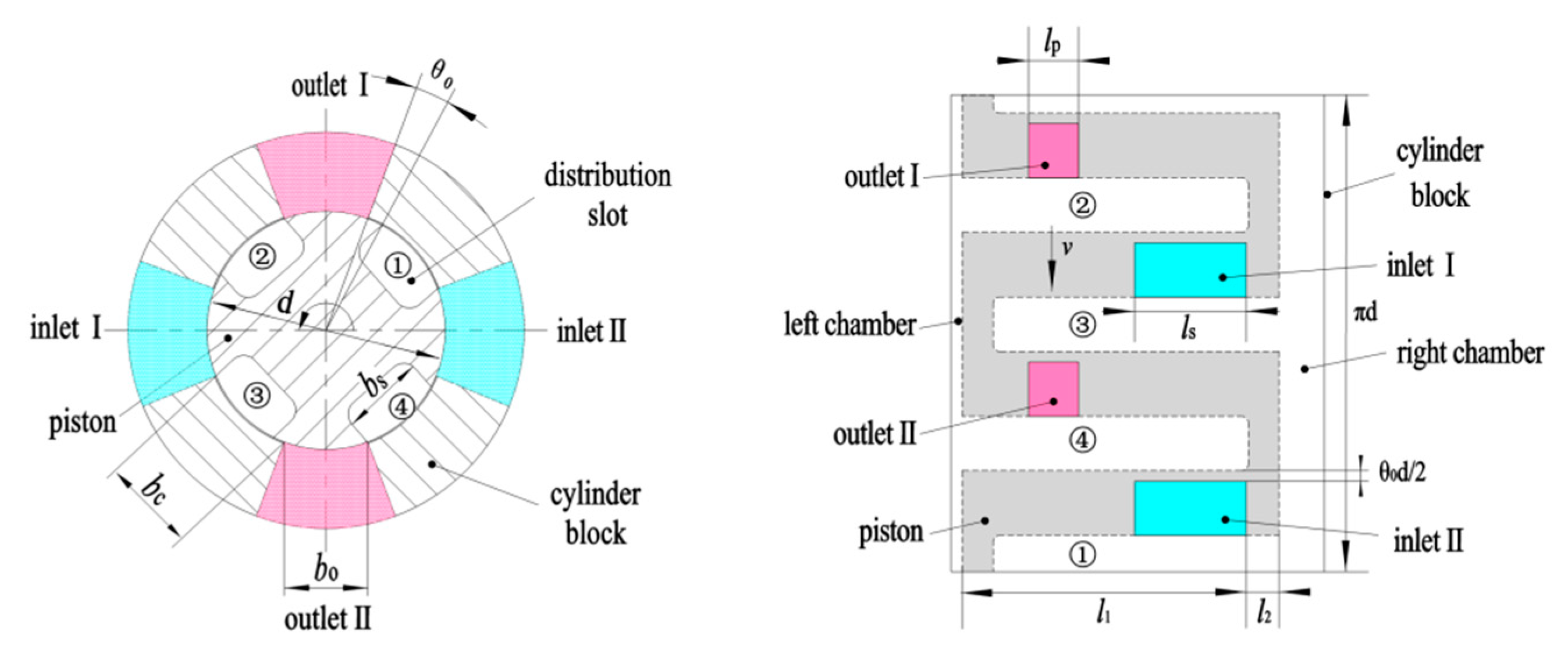
To reduce the additional pressure ripples and lower the fluid noise caused by backflow, the width between the piston slots under the structure with overlapping flow distribution ports is designed to be larger than the width of the cylinder block window (Figure 3), thus forming a corresponding central angle of θ0 for the covering portion. When the window of the cylinder block is just covered, the piston is in the limit position of reciprocating motion, and the corresponding roller is at the highest (or lowest) point of the guide rail. As the piston further rotates and moves, the distribution window does not open, and the volume of the right pump chamber decreases while the left pump chamber increases. Since the pump chamber is in a closed state, the pressure in the right pump chamber will increase. Conversely, the pressure in the left pump chamber will decrease. This phenomenon generates a pre-pressure that reduces the pressure difference both inside and outside the distribution window. When the piston rotates beyond the overlapped section, the backflow weakens as the distribution window opens, resulting in a reduction in additional pressure ripples.
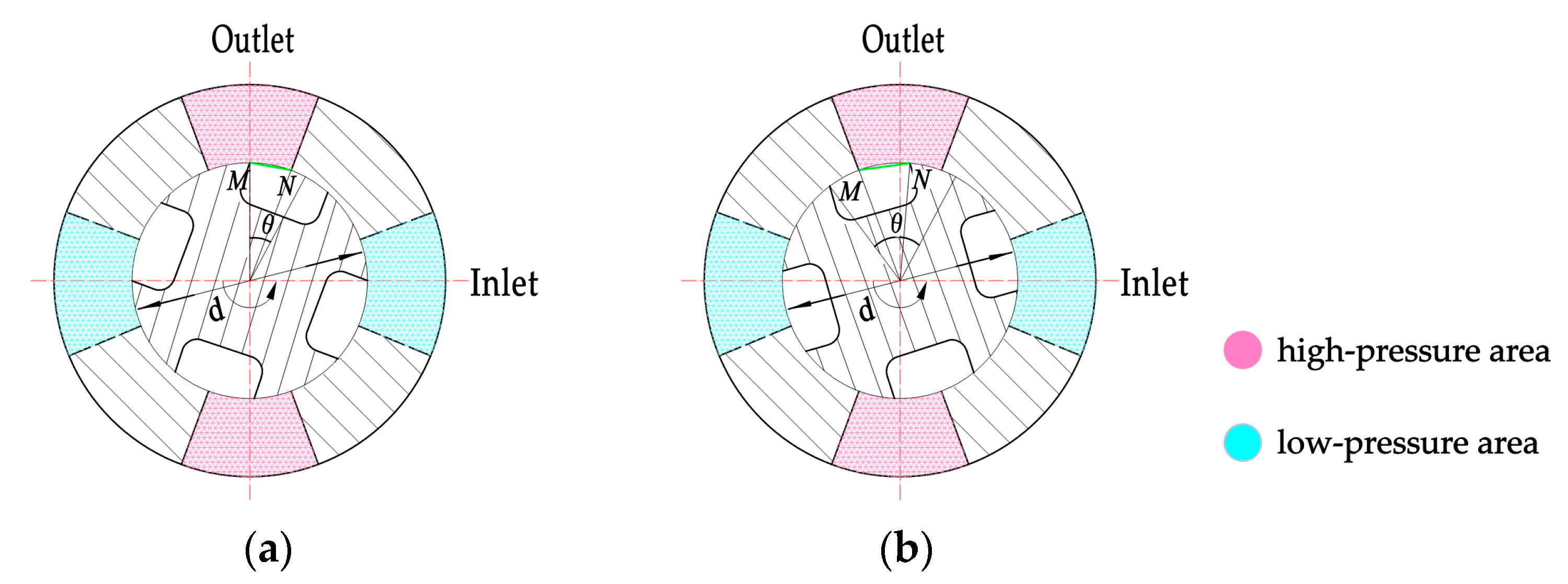
Figure 4 illustrates the flow distribution process of a 2D pump during one piston stroke with length H. The piston rotates and moves from the left most extreme position to the right most extreme position. The purple–red areas in the figure represent high pressure, while the light blue areas represent low pressure. Both pump chambers are in a closed state when the angle θ < θ0. As the piston moves to the right, the volume of the left pump chamber increases while the volume of the right pump chamber decreases. Therefore, the pressure in the left pump chamber decreases, and the pressure in the right chamber increases. As the angle θ exceeds θ0, the left pump chamber sucks in oil through the inlet while the right pump chamber discharges oil through the outlet. The pre-variation in the pressure inside the pump chamber reduces the pressure difference between the inside and outside of the pump chamber when the flow distribution port opens. When the piston rotates to θ = π/2, it reaches the right limit position. Throughout the subsequent π/2 period of continued piston rotation, it moves from the right limit position to the left limit position, experiencing the same pre-pressure change process in both pump chambers.

3. Analysis of the Pressure and Flow within the Piston Chambers

3.1. Flow Area of the Overlapped Distributor

Figure 3 shows that the sum of the slot width bs and the sealing width between the slots on the piston bc corresponds to a central angle of π/2. Likewise, on the cylinder block, the sum of the window width bo and the sealing width between the windows bc also corresponds to a central angle of π/2. When the central angle of the overlap corresponds to θ0, the central angle corresponding to the piston slot (cylinder block window) can be denoted as π/4 − θ0/2.
It can be seen that the shape of the flow distribution window of the overlapping distributor is rectangular. Let As and Ap denote the flow distribution port areas of the pump inlet and outlet, respectively. It follows that Ap can be expressed as
A p = 2 l p x v
where lp is the axial length of the cylinder block outlet opening, and xv is the real-time width of the variable flow distribution port.
The value of xv varies with the relative position of the piston and cylinder block as shown in Figure 5. For this, the expression of Ap can be derived from the range of the angle θ.
When 0 ≤ θ < θ0 and xv = 0, then Ap = 0.
When θ0θ < π/4 + θ0/2 and xv = M N ¯ , M N ¯ increases as θ increases and can be expressed as:
M N ¯ = d sin θ θ 0 2
where d is the diameter of the piston.
It is easy to obtain:
A p = 2 l p d sin θ θ 0 2
When π/4 + θ0/2 ≤ θ < π/2 and xv = M N ¯ , M N ¯ decreases as θ increases and can be expressed as:
M N ¯ = d sin π 4 θ 2
It is easy to obtain:
A p = 2 l p d sin π 4 θ 2
This can be consolidated as:
A p = 0 0 θ < θ 0 2 l p d sin θ θ 0 2 θ 0 θ < π 4 + θ 0 2 2 l p d sin π 4 θ 2 π 4 + θ 0 2 θ < π 2
Similarly, it can be derived:
A s = 0 0 θ < θ 0 2 l s d sin θ θ 0 2 θ 0 θ < π 4 + θ 0 2 2 l s d sin π 4 θ 2 π 4 + θ 0 2 θ < π 2
where ls is the axial length of the cylinder block inlet opening.

3.2. Volumetric Losses

The instantaneous pressure distribution within the piston chamber of a practical 2D pump ought to align with that of an ideal pump, per the pump distribution process. During the initial quarter revolution of the piston (0 ≤ θπ/2), the pressure p1 in the left chamber equals the suction pressure pl, while the pressure p2 in the right chamber is equal to the pressure ph at the pressure port. During the second quarter revolution of the piston (π/2 ≤ θπ), the pressure p1 in the left chamber becomes equal to the pressure ph, while the pressure p2 in the right chamber becomes equal to the suction pressure pl. The subsequent half-revolution repeats the same process for the chamber pressures. Figure 6 shows the pressure variation in the ideal pump chamber.
The calculation method of the internal leakage and discharge flow of the 2D pump can be summarized based on the past research [18]. When the piston rotates counterclockwise and moves to the left, as depicted in Figure 7, the left pump chamber becomes the high-pressure chamber, and the right becomes the low-pressure chamber. During operation, the pressure in the pump chamber is established by the method of gap-sealing. Therefore, several leakage paths are generated, including the axial inward leakage QSK that occurs between the high-pressure chamber and the low-pressure chamber through the gap between the piston and the cylinder block; the circumferential inward leakages QRA and QRD; and the external leakages QSE and QSI through the gap between the piston rod and the sealing ring.
The axial leakage flow rate QSK can be derived by the formula for concentric annular gap flow.
Q S K = π d δ 3 ( p 1 p 2 ) 12 μ l 2 π d δ 2 v k
where p1 and p2 are the pressure values in the chamber during compression and expansion, respectively. δ is the height of the gap, μ is the fluid dynamic viscosity coefficient, l2 is the seal length on one side of the slot, and vk is the mean speed of the piston’s linear motion.
The distribution slot experiences equal amounts of shear flow inward and outward along the circumference, which can be approximately canceled out. The circumferential leakage flows QRA and QRD can be expressed as:
Q R A = Q R D = l 1 l 2 ( p 1 p 2 ) δ 3 12 μ l r
where l1 is the piston slot length and lr is the circular contact length between the piston and cylinder block, which can be calculated by the expression in Equation (10) according to reference [11].
l r = d 2 θ d 2 π 2 + θ 0 θ d 2 θ π 2 d 2 π + θ 0 θ 0 < θ π 4 + θ 0 2 π 4 + θ 0 2 < θ π 2 π 2 < θ 3 π 4 + θ 0 2 3 π 4 + θ 0 2 < θ π
When the circumferential sealing band undergoes length variation, there is a point where the sealing band length becomes infinitely small. At this point, the high fluid velocity means that the flow is no longer laminar, resulting in transient leakage. Therefore, the circumferential internal leakage QR can be expressed as:
Q R = l 1 l 2 p 1 p 2 δ 3 3 μ l r 2 C d δ l 1 l 2 2 p 1 p 2 ρ s i g n p 1 p 2 l 1 l 2 p 1 p 2 δ 3 12 μ l r < C d δ l 1 l 2 2 p 1 p 2 ρ l 1 l 2 p 1 p 2 δ 3 12 μ l r > C d δ l 1 l 2 2 p 1 p 2 ρ
The external leakages through the gap between the piston rod and the sealing ring are denoted by QSE and QSI:
Q S E = π d s δ 3 ( p 1 p e ) 12 μ l 3 + π d δ s 2 v k
Q S I = π d s δ 3 ( p e p 2 ) 12 μ l 3 + π d s δ 2 v k
where ds is the piston rod diameter, pe is the out-cylinder block pressure, and l3 is the sealing length of the sealing ring.
The oil discharged will flow due to the pressure difference, causing the outlet flow to backflow during the pressure rise process after the pressure switch. Combined with the formula for orifice flow, the discharge flow Qp generated by the piston motion at this time can be expressed as:
Q p = n H π d 2 d s 2 s i g n p 1 p h C d A p 2 p 1 p h ρ
where Cd is the coefficient of flow, ρ is the fluid density, and H is the working stroke of the piston

3.3. Pressure Analysis in a Pump Chamber

According to the definition of the bulk modulus of elasticity of the oil, the piston chamber is regarded as a closed chamber, and the change in volume of the piston chamber has two sources [28], one is that the volume of the fluid changes when the fluid mass in the closed chamber remains unchanged, due to the reciprocating motion of the piston, and the volume in the closed chamber is expanded or compressed. At this time, the relationship between pressure and volume can be expressed as dp = −KdV/V. The other aspect is that the volume of the chamber remains unchanged, while the fluid mass changes due to the pressure difference between the piston chamber and the outlet, which causes the inflow and outflow of oil. At this time, the relationship between pressure and volume can be comprehensively expressed as dp = −KdV/V + Kqdt/V.
Based on this principle, a mathematical model is established, and the pressure change in the chamber is analyzed.
d p 1 d t = K V 1 Q p i + Q S K + Q S E + Q R d V 1 d t
d p 2 d t = K V 2 Q s i + Q S K + Q S I + Q R d V 2 d t
where V1 and V2 are the working volumes of the left and right chambers, respectively. K is the liquid bulk modulus of elasticity, and Qpi and Qsi are the real effective flow rates of output and suction, respectively.
The effective volume of the two pump chambers is given by:
V 1 = V M a x S k A k
V 2 = S k A k
The displacement Sk of the piston during reciprocating motion follows the law of equal acceleration and deceleration, as described previously [29], and is given by:
S k = 8 H π 2 ω t 2 8 H π 2 ω t 2 + 8 H π ω t H 8 H π 2 ω t 2 16 H π ω t + 8 H 8 H π 2 ω t 2 + 24 H π ω t 17 H 8 H π 2 ω t 2 32 H π ω t + 32 H ω t 0 ~ π 4 ω t π 4 ~ 3 π 4 ω t 3 π 4 ~ 5 π 4 ω t 5 π 4 ~ 7 π 4 ω t 7 π 4 ~ 2 π
where VMax is the maximum working volume of the single-side chamber, Ak is the effective ring area of the piston, and ω is the rotational angular velocity of the piston.
The changes in the volume of the two pump chambers can be expressed as:
d V 1 d t = d V 2 d t = v k A k
Combining the orifice flow formula, the actual inlet and outlet flow of the piston chamber is expressed as:
Q p i = s i g n p 1 p h C d A p 2 p 1 p h ρ
Q s i = s i g n p l p 2 C d A s 2 p l p 2 ρ
Since the following holds true:
d p 1 d θ = d p 1 ω d t = K ω V 1 Q p i + Q S K + Q S E + Q R d V 1 d t
d p 2 d θ = d p 2 ω d t = K ω V 2 Q s i + Q S K + Q S I + Q R d V 2 d t
The relationship between the pump chamber pressure and the angle of rotation can be obtained as follows:
d p 1 d θ = K ω v k A k s i g n p 1 p h C d A p 2 ( p 1 p h ) ρ π d δ 3 ( p 1 p 2 ) 12 μ l 2 π d δ 2 v k π d s δ 3 ( p 1 p e ) 12 μ l 3 + π d s δ 2 v k Q R V M a x S k A k d p 2 d θ = K ω v k A k s i g n p l p 2 C d A s 2 ( p l p 2 ) ρ π d δ 3 ( p 1 p 2 ) 12 μ l 2 π d δ 2 v k π d s δ 3 ( p e p 2 ) 12 μ l 3 + π d s δ 2 v k Q R S k A k

4. Simulation

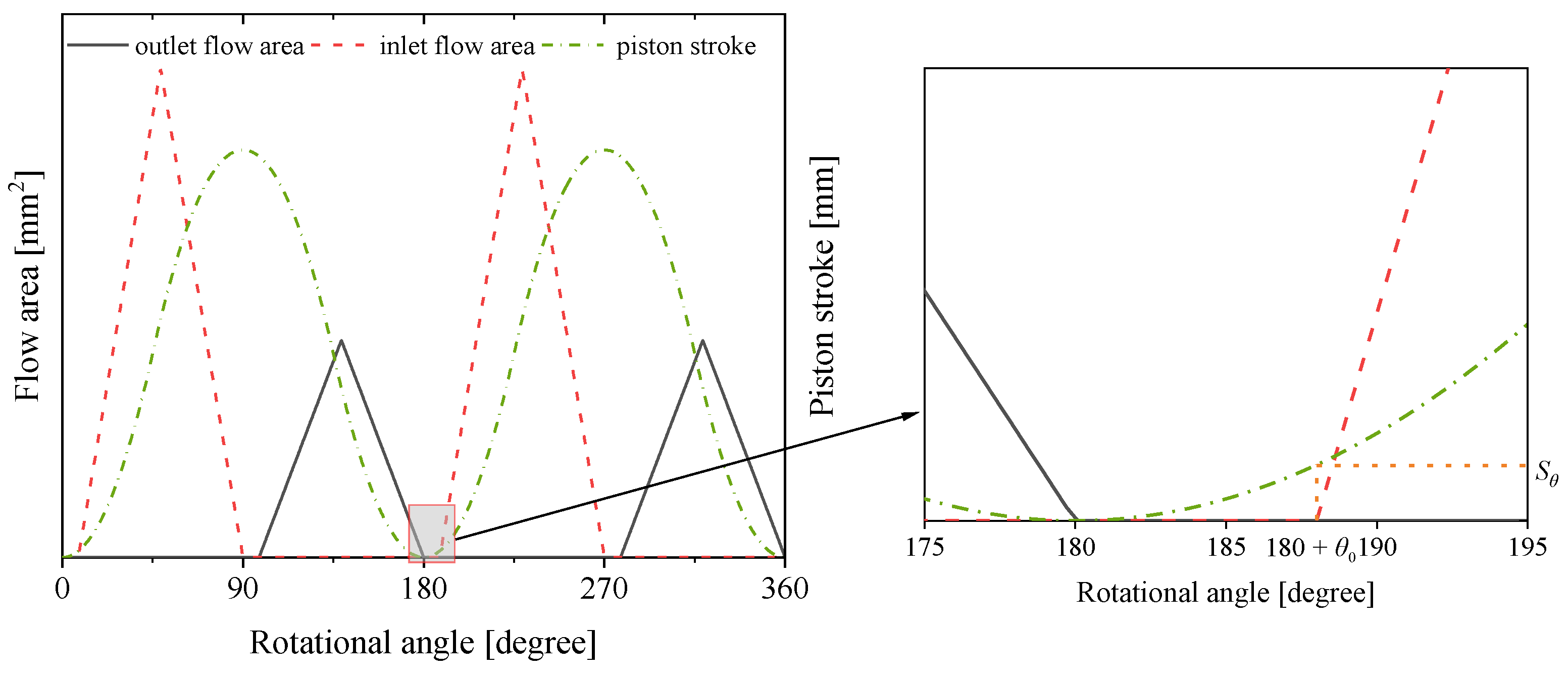
When a 2D pump rotates at a constant speed, the flow area of the pump outlet window and the piston stroke change according to Equations (6), (7) and (19), as illustrated in Figure 8. It can be observed that when the angle is within θ0, the pump outlet window is closed (Ap = 0), and the piston undergoes a displacement Sk.
By compiling and solving the equations in (14) and (25) with Matlab, the dynamic characteristics of the 2D pump were simulated and analyzed, and the curves of the instantaneous volumetric discharge and the pressure in the piston chamber can be obtained, respectively. According to the real structure design of the pump used for the test, the simulation parameters are set as shown in Table 1.
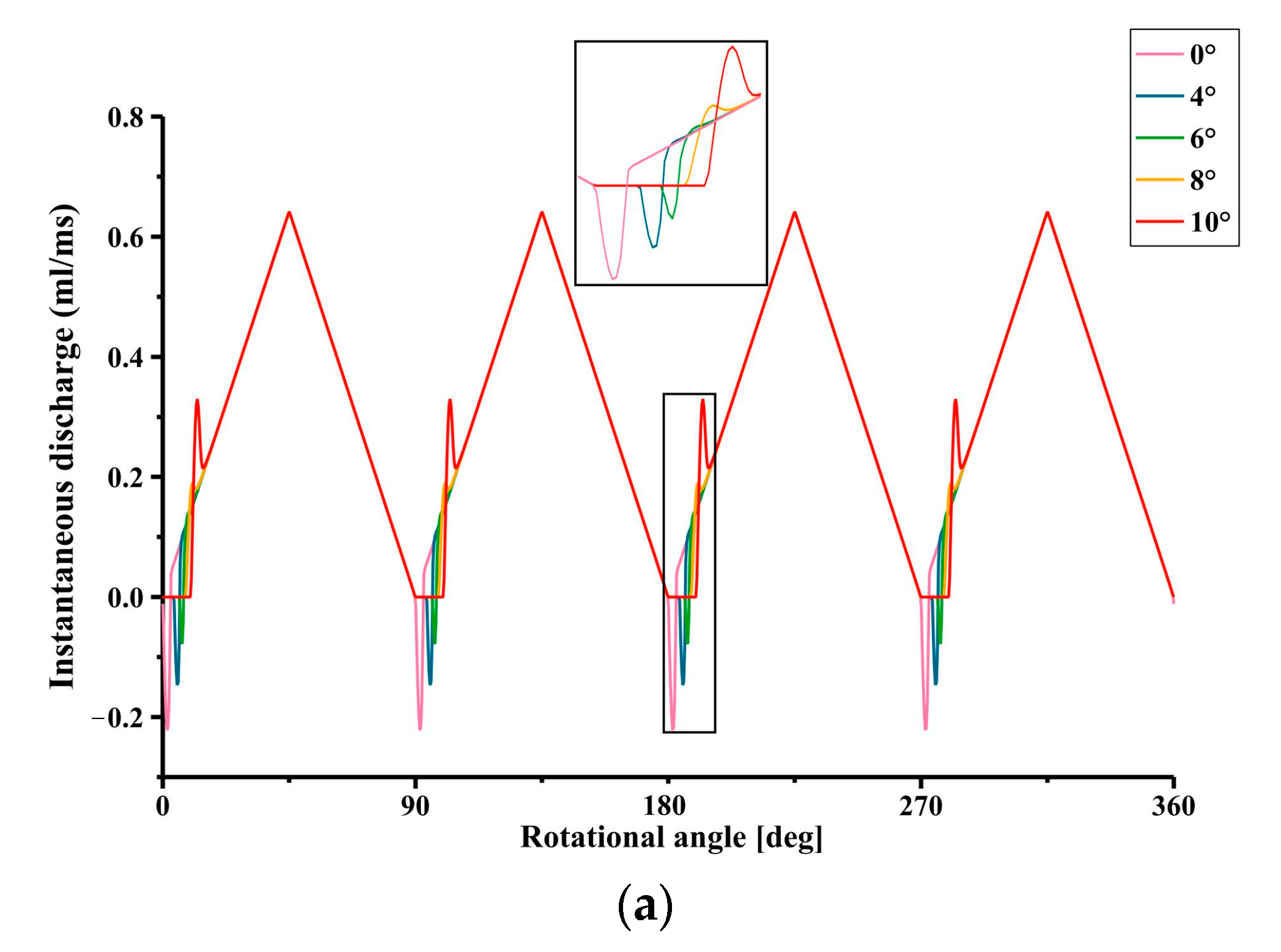
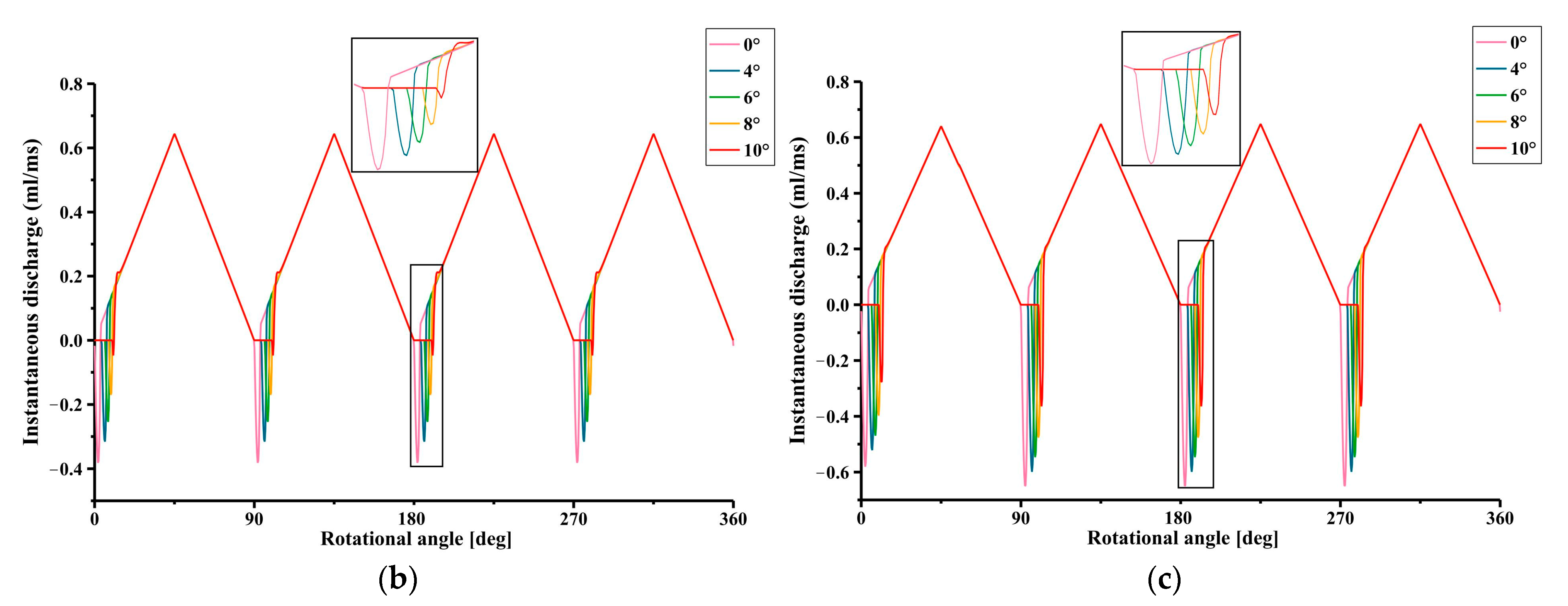
Figure 9 illustrates the simulated instantaneous volumetric discharge of the pump at motor speeds of 3000 r/min and pump loading pressures of 5, 10, and 20 MPa. The instantaneous volumetric discharge waveform has a triangular shape, with backflow occurring when the distribution window is opened. The degree of distribution window overlap plays a role in reducing or eliminating the backflow. In order to study the effect of varying degrees of overlap on pressure ripple and flow, we chose 0°, 4°, 6°, 8°, and 10° as the values of the overlap angle. These values cover the range of effective chamber pre-compression effect of the 2D pump, from no overlap (0°) to a large overlap (10°). At the same time, the intervals between the overlaps are uniform (2°), which can facilitate comparisons and analyses. For instance, as depicted in Figure 9a, the overlap of the distribution window at 8° produces a significant decrease in backflow. However, Figure 9c shows that even when the outlet pressure is high, a distribution window overlap of 10° cannot eliminate the backflow.
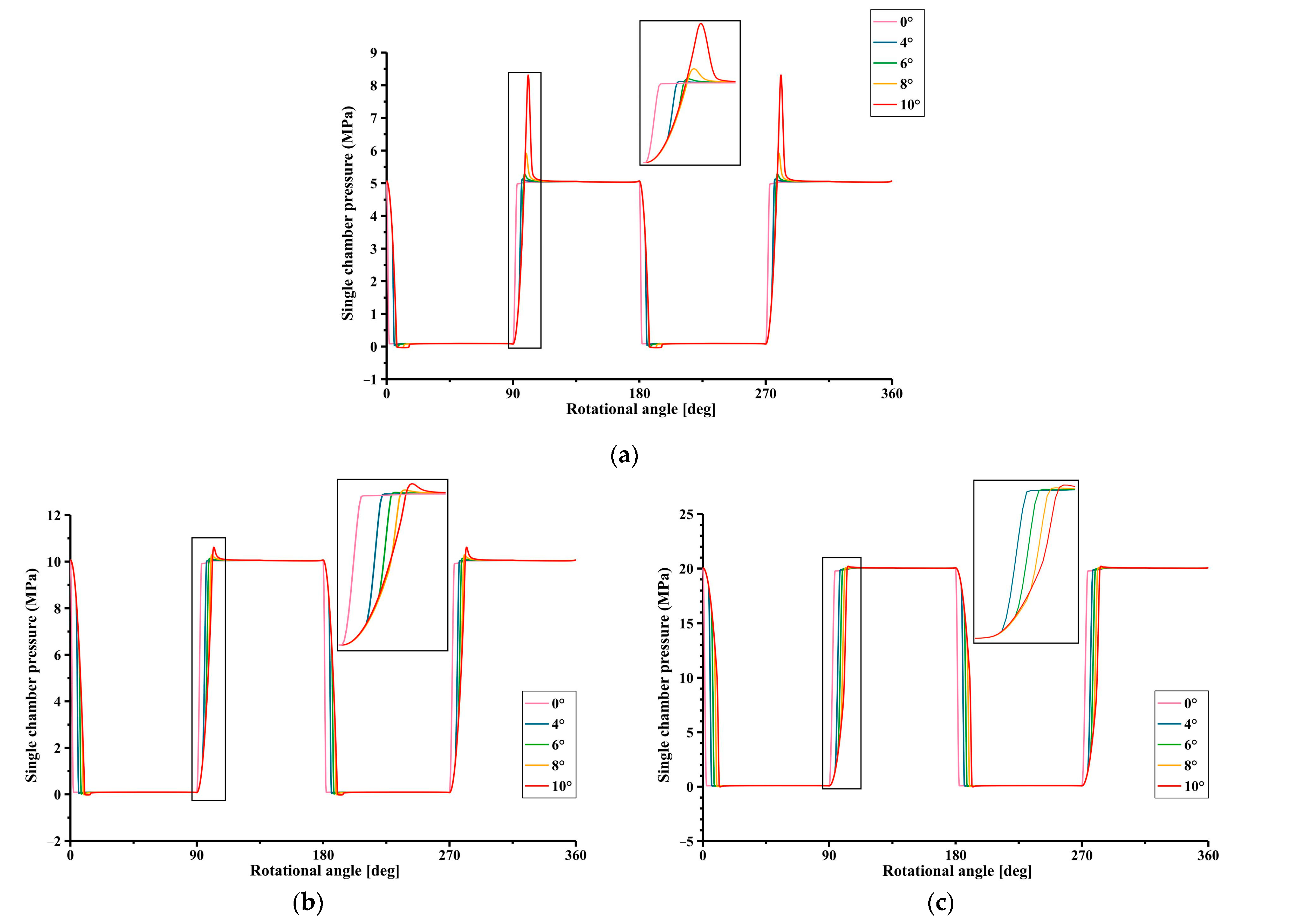
The instantaneous pressure changes are shown in Figure 10. As the degree of port overlap increases, the magnitude of the pressure transients during the distribution window opening decreases significantly. As portrayed in Figure 10c, when the outlet pressure is high, a distribution window overlap of 10° has the most significant effect in reducing pressure transients.

5. Experimental Research

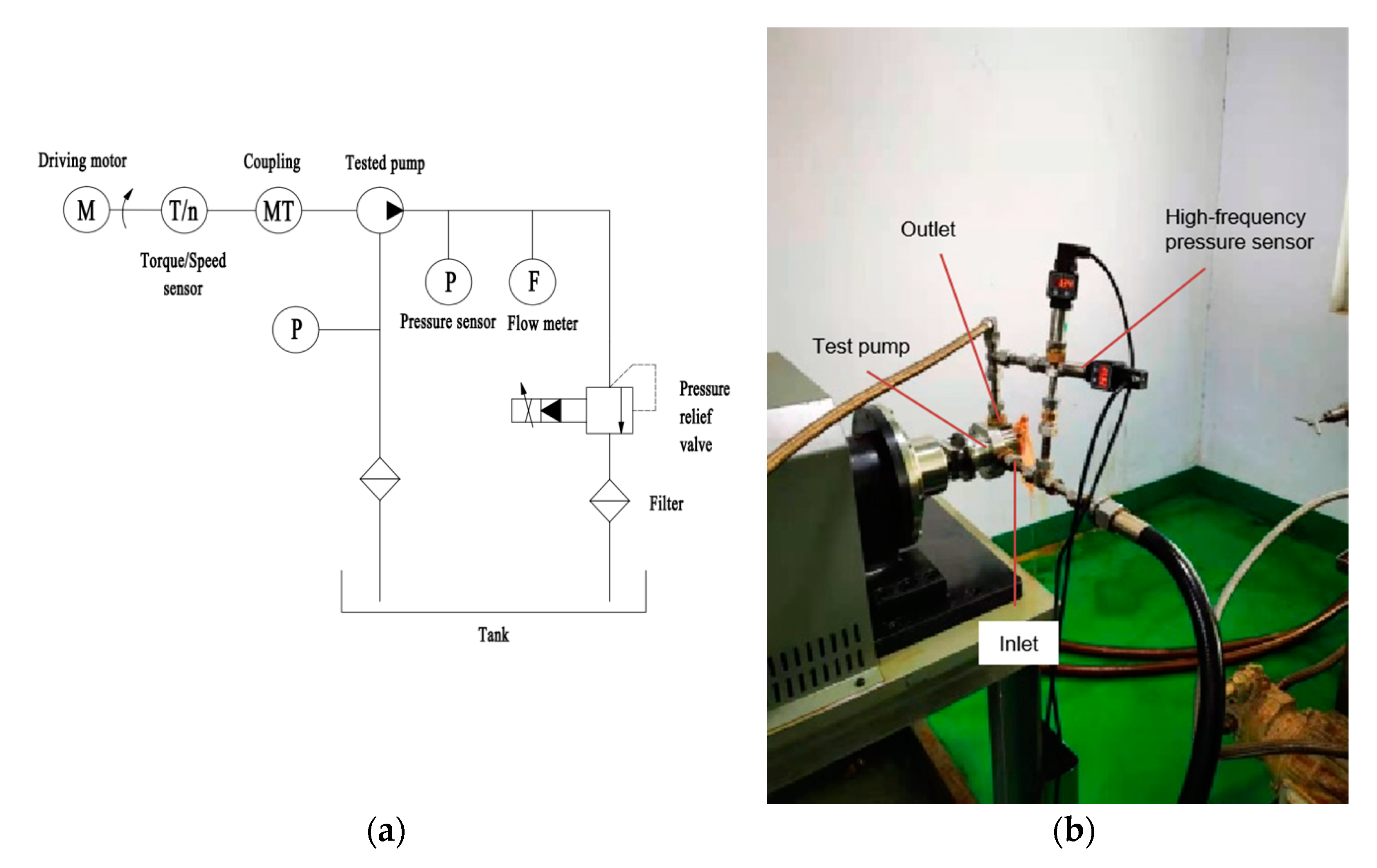
Two sets of cylinder blocks and pistons were processed to investigate the impact of the 2D pump’s flow distributor with an overlapped structure on its transient characteristics. One set had no overlap, and the other had an 8° overlap angle. An experimental platform was set up, as shown in Figure 11, and data were collected using the HM90(10 MPa)-H3-3-V2-F2 high-frequency pressure sensor of the HELM company, whose parameters are shown in Table 2. Through the pressure sensor, the outlet pressure data of different distribution structures under the same other conditions were recorded and plotted. At the same time, we used DELIXI company’s decibel meter to measure the working noise of the pump. The decibel meter was placed near the pump, and the working noise of the pump was recorded every five minutes when the pump was working continuously, and ten sets of data were obtained to calculate the average value. The experiment was conducted at a motor speed of 3000 r/min, and the pump outlet pressure was adjusted to 2.4 MPa.
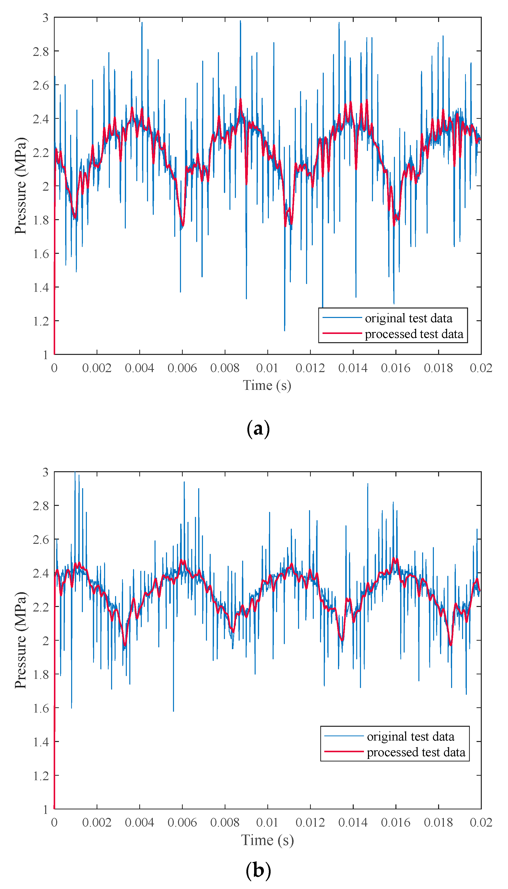
The original outlet pressure data obtained by experimental measurement contains many errors and interferences. To reduce their impact on the results, the original data was processed by low-pass filtering and three-point averaging methods. The comparison between the processed data and the original data is shown in Figure 12. Thanks to the overlapping structure of the flow distribution ports, the pressure ripple at the pump outlet decreased from 28.6% to 18.2%, and the average working noise was also reduced from 66.2 dB(A) to 64.1 dB(A).
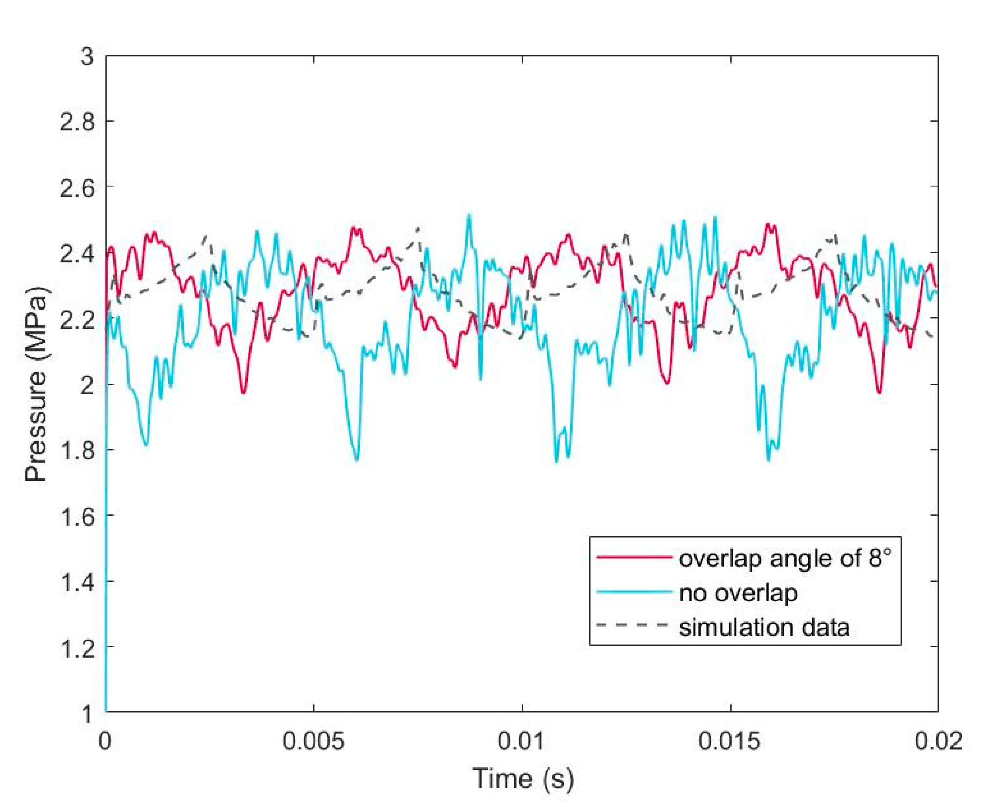
The experimental data of the pump outlet pressure was compared with the simulation result of 8 degrees overlap. As shown in Figure 13, the actual pressure change trend at the pump outlet is consistent with the simulation and has a similar ripple amplitude. The experimental results verify the restraint effect of the 2D piston pump port distribution with overlapping on the output pressure ripple.

6. Conclusions

This article introduced the novel design of a 2D pump that features an overlapping distribution port structure, and describes its working principle in detail. A mathematical model was developed to describe the pressure and flow characteristics of the pump, and simulations were conducted to analyze the transient pressure and flow rate changes of the distribution port at overlap angles of 0°, 4°, 6°, 8°, and 10°. A test bench was built to test and verify the actual effect of the 2D pump distribution port structure with overlapped. According to the simulation and experimental results, the following conclusions can be drawn.
First, by analyzing the pressure and flow change laws in the piston chamber, it can be known that the flow backflow caused by the pressure difference is an important reason for the large output pressure ripple of the 2D pump.
Second, under the common working conditions of the aviation piston pump, the simulation results show that the degree of distribution port overlap has a good effect on reducing the flow backflow when it is 8°, and can also effectively reduce the degree of pressure variation at the pump outlet. However, when the pump working pressure is too high, the distribution port overlap has a small effect on the flow backflow.
Finally, the experimental study verifies that the distribution port with overlap has a suppression effect for the output pressure ripple of the 2D pump. The experimental data show that under the conditions of 3000 r/min speed and 2.4 MPa load, the pump output pressure ripple decreases by ten percentage points, and the working noise decreases by 2.1 dB(A).

Author Contributions

Conceptualization, J.R.; Data curation, C.G.; Software, X.Y.; Supervision, J.R.; Visualization, Y.H.; Writing—original draft, T.X. and X.Y.; Writing—review and editing, T.X. All authors have read and agreed to the published version of the manuscript.

Funding

This research was funded by the National Natural Science Foundation of China (No. 51775500) and the National Key Research and Development Program of China (No. 2019YFB2005204).

Data Availability Statement

Data sharing not applicable.

Conflicts of Interest

The authors declare no conflict of interest.

References

  1. Chao, Q.; Zhang, J.; Xu, B.; Huang, H.; Pan, M. A review of high-speed electro-hydrostatic actuator pumps inaerospace applications: Challenges and solutions. J. Mech. Des. 2019, 141, 050801. [Google Scholar]
  2. Zhang, T.T. Trends and challenges of high-speed hydraulic pump technology in the era of electricization—According to Xu Bing’s report, an expert of Zhejiang University. Hydraul. Pneum. Seals 2022, 42, 103–107. [Google Scholar]
  3. Kaminaga, H.; Amari, T.; Niwa, Y.; Nakamura, Y. Development of knee power assist using backdrivable electrohydrostatic actuator. In Proceedings of the 2010 IEEE/RSJ International Conference on Intelligent Robots and Systems, Taipei, Taiwan, 18 October 2010; pp. 5517–5524. [Google Scholar]
  4. Sun, M.W.; Ouyang, X.P.; Mattila, J.; Yang, H.; Hou, G. One novel hydraulic actuating system for the lower-body exoskeleton one novel hydraulic actuating system for the lower-body exoskeleton. Chin. J. Mech. Eng. 2021, 34, 31. [Google Scholar] [CrossRef]
  5. Sun, M.W.; Ouyang, X.P.; Wang, Z.Z.; Liu, H.; Yang, H.Y. Cooperative control strategy of pump-controlled exoskeleton robot walking. J. Mech. Eng. 2022, 58, 159–169. [Google Scholar]
  6. Ko, T.; Kaminaga, H.; Nakamura, Y. Key design parameters of a few types of electro-hydrostatic actuators for humanoid robots. Adv. Robot. 2018, 32, 1241–1252. [Google Scholar] [CrossRef]
  7. Ruan, J.; Tong, C.W.; Li, S.; Feng, Z.J.; Shentu, S.N.; Jin, D.C.; Meng, B. Two-Dimensional Axial Piston Pump with Equal Acceleration and Equal Deceleration Track. Chinse patent CN 201510151253.3, 1 April 2015. [Google Scholar]
  8. Ruan, J.; Li, J.Y.; Jin, D.C. Research and feasibility verification of two-dimensional (2D) piston pump. J. Zhejiang Univ. Technol. 2017, 45, 264–269. [Google Scholar]
  9. He, H.B. Design and Experimental Study of Two Dimensional (2D) Piston Constant Pressure Variable Pump. Master’s Thesis, Zhejiang University of Technology, Hangzhou, China, 2017. [Google Scholar]
  10. Huang, Y.; Ruan, J.; Zhang, C.; Ding, C.; Li, S. Research on the mechanical efficiency of high-speed 2D piston pumps. Processes 2020, 8, 853. [Google Scholar] [CrossRef]
  11. Huang, Y.; Ruan, J.; Chen, Y.; Ding, C.; Li, S. Research on the volumetric efficiency of 2D piston pumps with a balanced force. Energies 2020, 13, 4796. [Google Scholar] [CrossRef]
  12. Wang, H.Y.; Li, S.; Ruan, J. Design and research of two-dimensional fuel pump with balanced inertia force. Acta Aeronaut. E.T. Astronaut. Sin. 2022, 43, 424696. [Google Scholar]
  13. Zhu, K.; Ruan, C.; Wang, H.; Li, S.; Ruan, J. Analysis of the torque loss of high-speed transmission mechanism with a stacked roller set. Machines 2021, 9, 140. [Google Scholar] [CrossRef]
  14. Zhang, C.; Ruan, J.; Xing, T.; Li, S.; Meng, B.; Ding, C. Research on the volumetric efficiency of a novel stacked roller 2D piston pump. Machines 2021, 9, 128. [Google Scholar] [CrossRef]
  15. Shentu, S.N.; Ruan, J.; Qian, J.Y.; Meng, B.; Wang, L.F.; Guo, S.S. Study of flow ripple characteristics in an innovative two-dimensional fuel piston pump. J. Braz. Soc. Mech. Sci. Eng. 2019, 41, 1–15. [Google Scholar] [CrossRef]
  16. Ruan, J.; Jin, D.C.; Shentu, S.N.; Wu, C.S. Research and feasibility verification of two–dimensional (2D) tandem pump. Chin. Hydraul. Pneum. 2017, 11, 1–5. [Google Scholar]
  17. Jin, D.C. Research on Design Method and Experimental Verification of Two-Dimensional Piston Pump. Ph.D. Thesis, Zhejiang University of Technology, Hangzhou, China, 2019. [Google Scholar]
  18. Shentu, S.N. Research on Flow Characteristics of Electric Two-Dimensional Piston (2D) Fuel Pump. Ph.D. Thesis, Zhejiang University of Technology, Hangzhou, China, 2020. [Google Scholar]
  19. Ding, C.; Huang, Y.; Zhang, L.; Ruan, J. Investigation of the churning loss reduction in 2D motion-converting mechanisms. Energies 2021, 14, 1506. [Google Scholar] [CrossRef]
  20. Jin, D.C.; Ruan, J. Design and research of two-dimensional fuel pump. Acta Aeronaut. E.T. Astronaut. Sin. 2019, 40, 422730. [Google Scholar]
  21. Qian, J.Y.; Shentu, S.N.; Ruan, J. Volumetric efficiency analysis of two-dimensional piston aviation fuel pump. Acta Aeronaut. E.T. Astronaut. Sin. 2020, 41, 423267. [Google Scholar]
  22. Xing, T.; Xu, Y.Z.; Ruan, J. Two-dimensional piston pump: Principle, design, and testing for aviation fuel pumps. Chin. J. Aeronaut. 2020, 33, 1349–1360. [Google Scholar] [CrossRef]
  23. Ding, C.; Zhu, Y.H.; Liu, L.; Tong, C.W. Research on a novel flowmeter with parallel two-dimensional pistons as its metering units. IEEE Access 2019, 7, 110912–110927. [Google Scholar]
  24. Ding, C.; Zhang, L.C.; Zhu, Y.H.; Ruan, J.; Tong, C.W. Modified mathematic model of a parallel two-dimensional piston flowmeter. Flow Meas. Instrum. 2021, 79, 101929. [Google Scholar]
  25. Ding, C.; Chen, H.; Zhang, L.; Xia, N.; Ruan, J. An investigation on the dynamic characteristics of a two-dimensional piston flowmeter. Adv. Mech. Eng. 2022, 14. [Google Scholar] [CrossRef]
  26. Ding, C. Investigation on two-dimensional piston dynamic flowmeter. Trans. Chin. Soc. Agric. Mach. 2022, 53, 450–458. [Google Scholar] [CrossRef]
  27. Guo, S.R.; Chen, J.H.; Lu, Y.L.; Wang, Y.; Dong, H.K. Hydraulic piston pump in civil aircraft: Current status, future directions and critical technologies. Chin. J. Aeronaut. 2020, 33, 16–30. [Google Scholar] [CrossRef]
  28. Ma, J.N. Study on Flow Ripple and Valve Plate Optimization of Axial Piston Pump. Ph.D. Thesis, Zhejiang University, Hangzhou, China, 2009. [Google Scholar]
  29. Shentu, S.N. Optimization analysis of flow characteristic and distribution window of 2D pump. Trans. Chin. Soc. Agric. Mach. 2019, 50, 403–410. [Google Scholar]
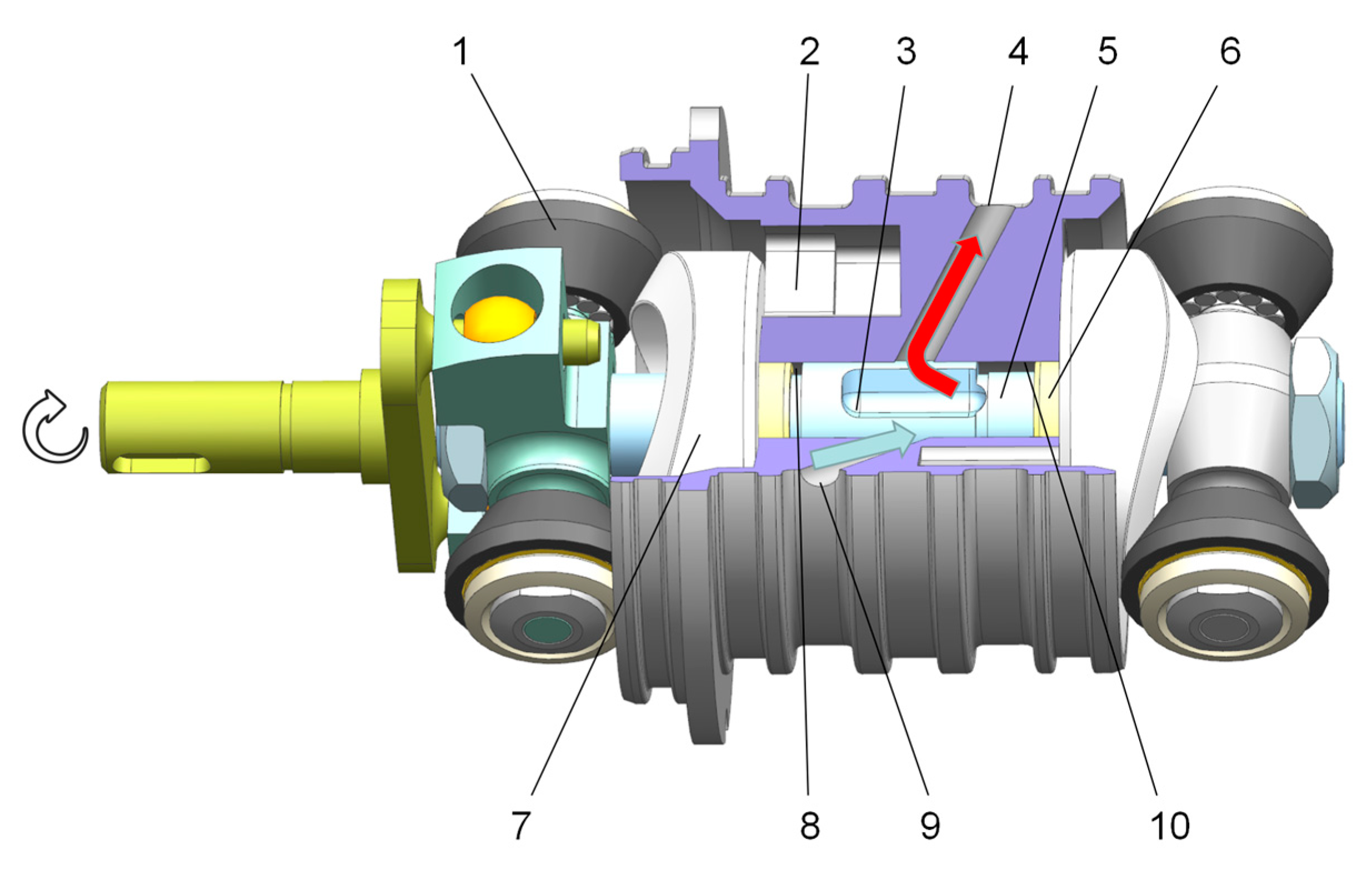
Figure 1. The internal structure of a 2D pump core. 1-Roller; 2-Cylinder block; 3-Distributing slot; 4-Outlet; 5-Piston; 6-Sealing ring; 7-Cam guide rails; 8-Left chamber; 9-Inlet; 10-Right chamber.
Energies 16 04303 g001
Figure 2. Section scheme of the distributor and its circumferential expansion.
Energies 16 04303 g002
Figure 3. Section schematic of the overlapped distributor and its circumferential expansion.
Energies 16 04303 g003
Figure 4. The distribution process during stroke length H.
Energies 16 04303 g004
Figure 5. Section at different relative positions of piston and cylinder block: (a) θ0θ < π/4 + θ0/2; (b) π/4 + θ0/2 ≤ θ < π/2.
Energies 16 04303 g005
Figure 6. Simplified pressure profile within the piston chambers of the 2D pump: (a) left chamber pressure and (b) right chamber pressure.
Energies 16 04303 g006
Figure 7. Schematic diagram of leakage.
Energies 16 04303 g007
Figure 8. Variation of outlet flow area and piston stroke with rotational angle.
Energies 16 04303 g008
Figure 9. Instantaneous volume discharge at loading pressures of (a) 5 MP, (b) 10 MP, and (c) 20 MP.
Energies 16 04303 g009aEnergies 16 04303 g009b
Figure 10. Instantaneous pressure of a single-side chamber when the loading pressure is (a) 5 MP, (b) 10 MP, and (c) 20 MP.
Energies 16 04303 g010
Figure 11. Schematic diagram of the test bench: (a) system schematic diagram; and (b) appearance of the test bench.
Energies 16 04303 g011
Figure 12. Comparison between original and processed test data for the cases of (a) no overlap and (b) a distribution port overlap angle of 8°.
Energies 16 04303 g012
Figure 13. Comparison of experimental data and simulation results at an 8° overlap angle.
Energies 16 04303 g013
Table 1. Main parameters of the simulation.
ParameterValueParameterValue
Bulk modulus of the oil K (MPa)1400Flow rate coefficient Cd0.62
Oil dynamic viscosity μ (Pa·s)3.91 × 10⁻²Cylinder block outlet opening length lp (mm)8
Oil density ρ (kg/m3)850Cylinder block inlet opening length ls (mm)18
Out-cylinder block pressure pe (MPa)0Piston slot length l1 (mm)46
2D piston diameter d (mm)24.4Sealing length on one side of the slot l2 (mm)5
Piston rod diameter ds (mm)16Sealing length of the sealing ring l3 (mm)28
Piston working stroke H (mm)6Gap width δ (mm)0.01
Table 2. Parameters of HM90(10 MPa)-H3-3-V2-F2.
DescriptionValveDescriptionValve
Pressure range10 MPaBandwidth (−3 dB)200 KHz
Combined non-linearity, hysteresis, and repeatability±0.1% FSOperating temperature range−50 °C to + 120 °C
Thermal sensitivity shift±0.1%/10 °CThermal zero shift±0.1% FS/100 °C
Disclaimer/Publisher’s Note: The statements, opinions and data contained in all publications are solely those of the individual author(s) and contributor(s) and not of MDPI and/or the editor(s). MDPI and/or the editor(s) disclaim responsibility for any injury to people or property resulting from any ideas, methods, instructions or products referred to in the content.