Review

Review of Measuring Methods, Setups and Conditions for Evaluation of the Inductive Instrument Transformers Accuracy for Transformation of Distorted Waveforms

Institute of Mechatronics and Information Systems, Lodz University of Technology, 90-537 Lodz, Poland
*
Author to whom correspondence should be addressed.
Energies 2023, 16(11), 4360; https://doi.org/10.3390/en16114360
Submission received: 30 April 2023 / Revised: 16 May 2023 / Accepted: 24 May 2023 / Published: 26 May 2023
(This article belongs to the Section F: Electrical Engineering)

Abstract

:
In this review article, ideas for the development of measuring methods and setups to test inductive instrument transformer accuracy for the transformation of distorted current or voltage are analyzed. This article proposes limiting values for ratio error and phase displacement at harmonics. Moreover, the manuscript discusses some remarks about the required test waveform of voltage and current, as well as the operating conditions of the inductive instrument transformer during the test. This includes designation of the number of harmonics, their RMS values and phase angles in relation to the fundamental component, as well as the required load of the VT’s and CT’s secondary winding. The aim of this work is also to show the common requirements and principles of developed methods and measuring setups to justify the proposed solution.

1. Introduction

Due to the nonlinearity of the magnetic core’s magnetization characteristics of inductive instrument transformers (ITs), they must be evaluated in their rated conditions of exploitation. Therefore, in the case of the inductive voltage transformers (VT), the primary voltage of the rated RMS value with some content of higher harmonics must be supplied to the primary winding. Inductive current transformers (CTs) require the primary current of the rated RMS value with some content of higher harmonics to be supplied to the primary winding. This implies three main problems that should be solved to perform the test: generation of distorted primary current or voltage, provision of appropriate reference device, and measuring apparatus. The first one may be solved by utilizing the wideband arbitrary power supply and step-up transformer [1,2]. In the case of the window-type inductive current transformer, another solution is to perform the test in its amper-turns conditions [3,4,5,6,7,8]. The disadvantage of this approach is that additional primary winding must be performed. However, a reference transducer is not necessary. In the measuring setup, where the step-up current or voltage transformers are used, such a device is essential for the evaluation of distorted current or voltage transformation accuracy. The reference transducer may be the window-type inductive CT previously tested for the transformation of distorted current harmonics [3]. The wideband current transducer/ active current sensor may also be used [9,10,11,12,13]. However, in this case, the voltages from current shunts are compared because there is a need for adjustment of the current ratio. In the case of measuring setup for VT, the reference source of distorted voltage may be the reference voltage divider [14,15,16,17,18,19,20,21,22,23]. The last problem that must be solved is to ensure an appropriate measuring apparatus. The devices commonly used by scientists are data acquisition boards, digital power meters, and lock-in amplifiers [24,25,26,27,28]. The accuracy of inductive CT and VT strongly relies on the load’s value and power factor in the secondary winding. The wideband accuracy of inductive CTs is primarily affected by the generation of low-order higher harmonics in its secondary current due to the non-linear magnetization characteristic of the magnetic core [4,5,14,29]. This phenomenon leads to additional distortion in the secondary current of inductive CTs, even for the transformation of sinusoidal currents. On the other hand, inductive VT wideband accuracy is mainly influenced by resonance [16,18,20,30,31]. This condition is characterized by the rapid increase with frequency of the value of the higher harmonic in the secondary voltage for its same primary voltage. Moreover, it is detected when a high value of the phase angle between the primary and secondary voltage harmonic occurs. However, self-generation may also be present during the operation of inductive VTs [14,15,16,18].

2. The Limiting Values of Ratio Error and Phase Displacement at Harmonic

There are no IEC or IEEE standard requirements for tests of distorted current/voltage transformation by inductive instrument transformers (ITs). Optional requirements will be introduced by the new edition of the standard IEC 61869-1 in the year 2023. In paper [32], the extension of routine tests of the inductive CTs is proposed (Table 1).
Further tightening of these requirements would concern adaptation of the limiting values of current error and phase displacement, as presented for 100 Hz to 1 kHz on all ranges of frequencies. Moreover, in the case of inductive CTs, the range of frequencies may extend up to 5 kHz [5]. Therefore, the limits of errors as presented in the standard IEC 61869-2 for 5% (highest values–worst case of operation) of the rated primary current may be adopted for the frequency range of the distorted current harmonics from 50 Hz to 5 kHz. In the case of modern inductive CTs (produced with utilization of the magnetic materials ensuring sufficient magnetic permeability with frequency of transformed current), their frequency range of operation for transformation of distorted current is limited by self-generation of the low order higher harmonics. Similar limiting values of voltage error and phase displacement at harmonics may be proposed for inductive VTs (Table 2).
Further tightening of these requirements would concern adaptation of the limiting values of voltage error and phase displacement as presented for 100 Hz to 1 kHz on all ranges of frequencies. Moreover, in the case of inductive VTs, the range of frequencies may extend up to 5 kHz [31]. Therefore, the limits of errors as presented in the standard IEC 61869-3 for the rated primary voltage may be adopted for the frequency range of the distorted voltage harmonics from 50 Hz to 5 kHz. In the case of the inductive VTs, their frequency range of operation is limited by resonance for the higher harmonic of distorted primary voltage. This problem mainly results from the leakage inductance and parasitic capacitance of its primary winding. A supplied low value of wide frequency sinusoidal voltage into primary winding of the tested VTs ensures proper identification of the resonance frequencies for transformation of distorted voltage harmonics [17,31,33]. However, in several tested MV units, resonance was not detected up to 5 kHz [16,20].

3. The Required Load of the VT’s and CT’s Secondary Winding and Test Waveform of Voltage and Current

The nonlinearity of the magnetization characteristic of the inductive IT’s magnetic core requires that their transformation accuracy for distorted current/voltage in the rated operation conditions be tested. Therefore, the inductive CTs for measuring purposes must be tested for 5%, 20%, 100%, 120% or 150%/200% of rated primary current. Inductive VTs for measuring purposes must be tested for 80%, 100%, 120% or 150% of rated primary voltage. The requirements for the primary waveform are not clearly defined in the IEC and IEEE standards [34,35,36,37]. In accordance with standard IEC 61869-6, the tests for accuracy at harmonics should be performed for the rated input signal at the rated frequency, also consisting of a percentage of the rated primary input signal with each considered harmonic [38]. This requirement results from nonlinear phenomena, which should be considered in the case of inductive ITs. Moreover, for practical purposes, the standard allows us to test the accuracy of inductive ITs with signals consisting of one single higher harmonic. However, its level is not specified. It results from our studies that the tests with distorted current/voltage containing primary component and one higher frequency harmonic are reliable. Only in the case of the inductive CTs may the results be influenced by the 3rd higher harmonic [14,29]. Furthermore, the phase angle between the higher harmonics and the fundamental harmonic in the distorted primary current/voltage significantly impacts the ratio errors and phase displacements of low-order higher harmonics up to a frequency of 500 Hz [5,14,16,29,39]. During the tests, the distorted current/voltage must contain at least one single higher harmonic, with its percentage value equal to 10%. This is a compromise between the level of the low and high order higher harmonics required for testing. The high frequency component has no influence on the value of the magnetic flux density in the magnetic core as its value decreases with frequency. The high RMS value of the low order higher harmonics has a significant influence on the total magnetic flux density in the magnetic core. Therefore, the values of current/voltage error and phase displacement at harmonics determined for transformation of the distorted current/voltage are influenced by the RMS value of the fundamental component, RMS values of the low order higher harmonics and the phase angle between them and the primary component. Moreover, the load of the secondary winding and its power factor are still important.
During the tests of accuracy at harmonics, the loads of the secondary winding should be the same as for transformation of sinusoidal current/voltage with rated frequency. In the case of the inductive VTs with the rated apparent power of the secondary winding from 10 VA to 100 VA, the test should be performed for 100% and 25% of the rated load with a power factor equal to 0.8 ind. If the rated apparent power of the tested inductive VT is from 1 VA to 10 VA, the test should be performed for 100% of the rated load with a power factor equal to 1 and in the non-load state. In the case of the inductive CTs, the test of transformation accuracy of sinusoidal and distorted current should be performed for 100% and 25% of the rated load of the secondary winding. If its rated apparent power is equal to or higher than 5 VA, the power factor is equal to 0.8 ind. If it is from 1 VA to 5 VA, the test should be performed with a power factor equal to 1. This paper [6] discusses the impact of the load power factor of the secondary winding of inductive CTs on their accuracy. If the power factor of the load is equal to 0.8 ind. instead of 1, a significant increase of the values of current error and phase displacement is observed. In the range of the low order higher harmonics, the self-generation phenomenon is more intensive as the secondary voltage increases with frequency, especially for higher currents and load. The transformation accuracy of higher frequency components of the distorted current also deteriorated due to the increase of the secondary winding load. In the case of the inductive VTs, the load power factor equal to 0.8 is more advantageous than 1. The increase of the secondary winding load with the frequency of the transformed higher harmonic causes a decrease in its secondary current and an increase in the transformation accuracy.

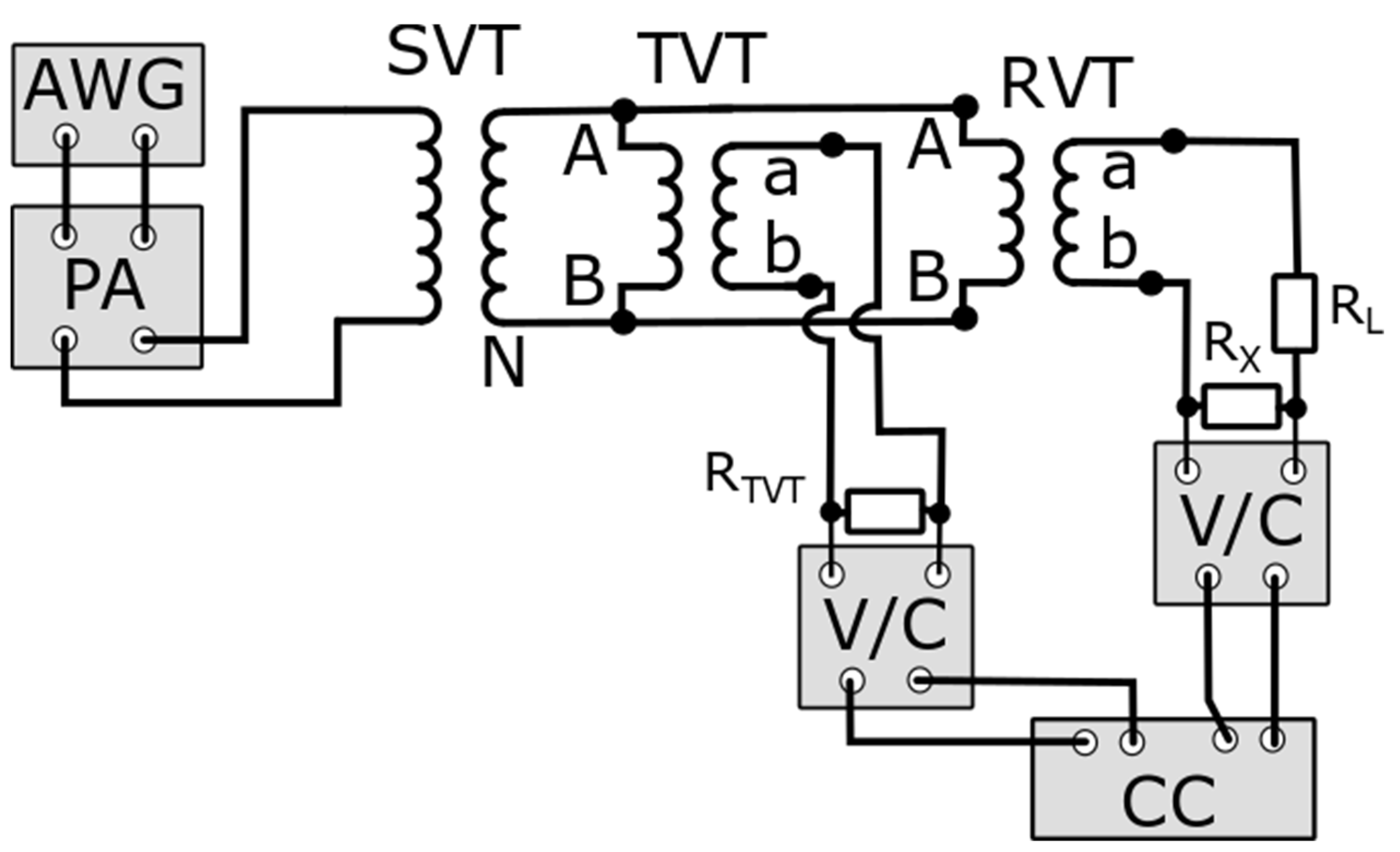
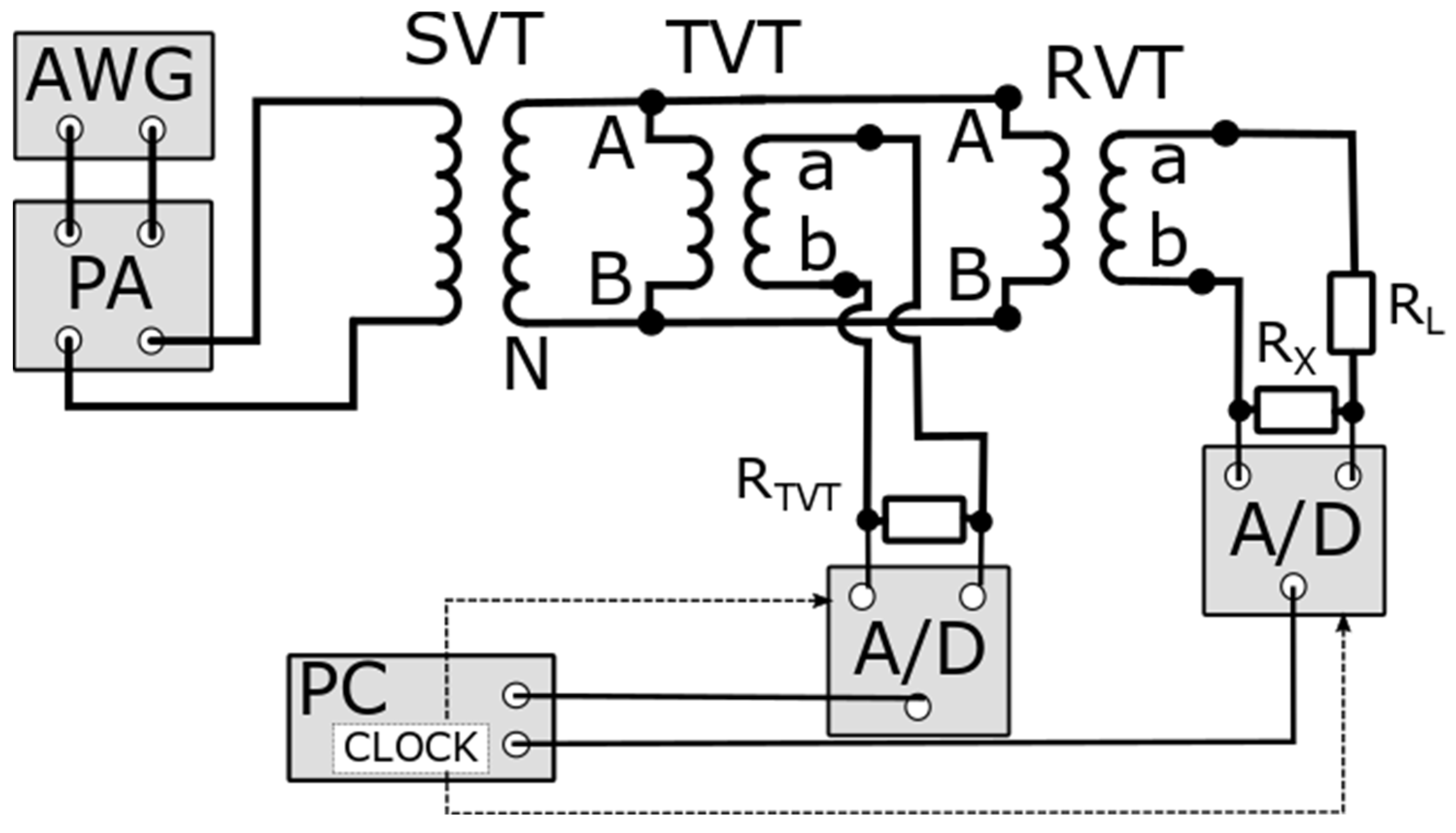
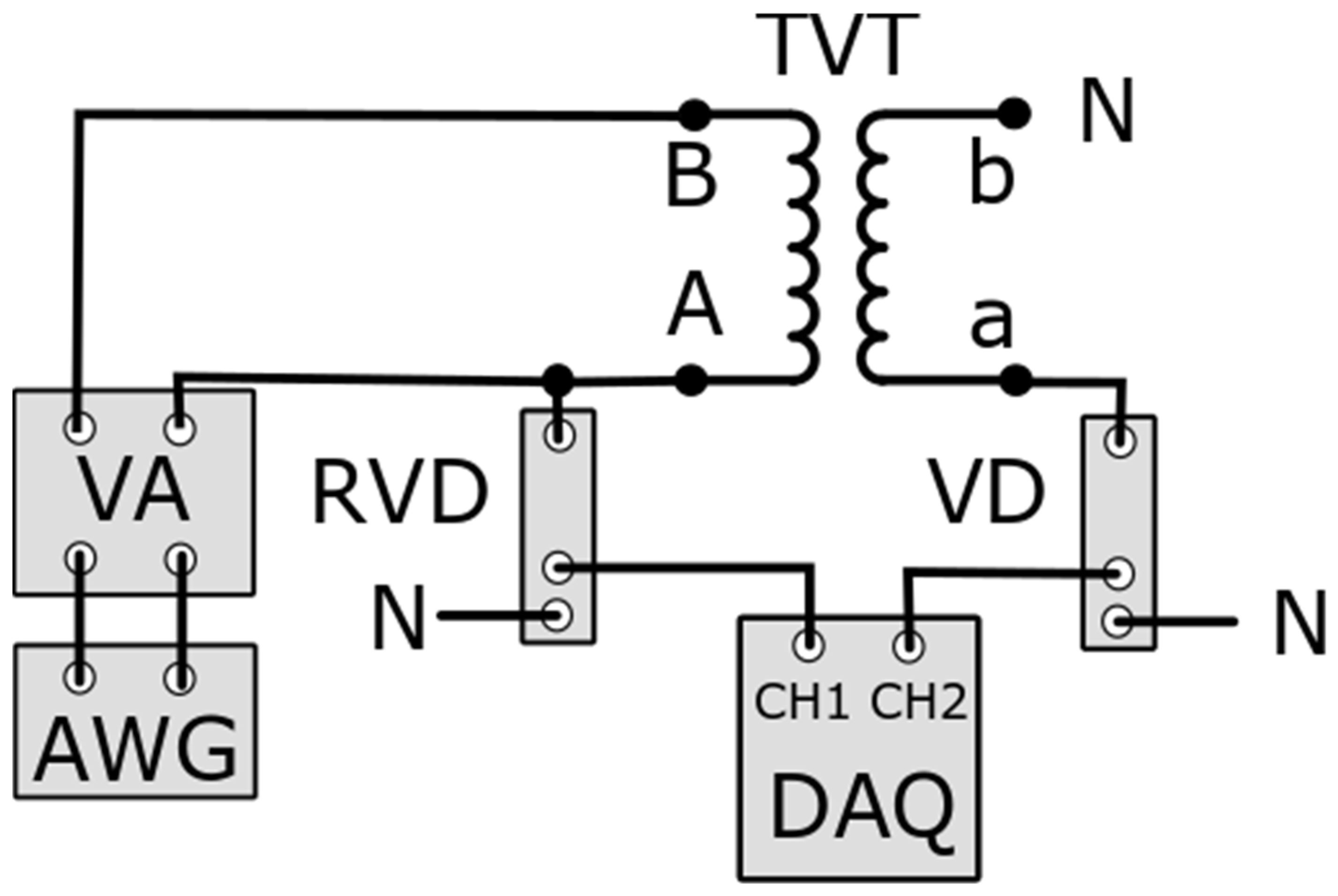
4. Measuring Setups for Evaluation of the Transformation Accuracy of Distorted Voltage by Inductive VTs

In the beginning, it is worth considering the ideas of the measuring setups to test the transformation accuracy of distorted voltage presented in standard IEC 61869-6 for the low-power instrument transformers. Such devices are characterized by negligibly rated output power. There are three proposals for voltage that may also be at least partially adopted to conventional instrument transformers. The first measurement setup for analogue accuracy measurement of voltage transformer is presented in Figure 1.
The AWG and PA are used to supply the measurement setup. This enables the possibility of generating distorted voltage with an adjustable level of harmonics and their phase angle in relation to the fundamental component. The SVT is used to step up the voltage from the PA to obtain its required RMS value for a given tested VT, taking into consideration its rated primary voltage. The RX shunt is used to adjust the output voltage of the RVT to the output voltage of the TVT. The core of this idea lies in the applied measuring equipment. In this case, the LiA is used. Therefore, the voltage may be measured at a selectable frequency. The typical RMS value of the input voltage is 1 V. To test conventional voltage transformers, the voltage dividers at the output of RVT and TVT must be used.
In Figure 2, the idea of the measurement setup for analogue accuracy measurement of the low-power voltage transformer with current comparator in accordance with IEC 61869-6 is presented.
In this measurement setup, in relation to the previous one, instead of the lock-in amplifier, the current comparator CC is used. This requires the use of additional voltage/current converters. In the technical report IEC 61869-103, the solution is proposed to use a voltage comparator [40]. Then, to test conventional voltage transformers, the voltage dividers at the output of RVT and TVT may be required depending on the permissible input voltage level of this device. Moreover, current or voltage comparators with the possibility of detecting the difference for harmonic of distorted current/voltage are not developed for instrument transformers.
In Figure 3, the concept of the measurement setup for digital accuracy measurement of the low-power voltage transformer in accordance with IEC 61869-6 is presented.
Analogue-to-digital converters are used to obtain the digital signal from voltages on RTVT load and RX shunt. It is required that the A/Ds are synchronized. This idea is the closest one to the typically used digital acquisition board and digital power meter.
The papers [16,20,31] discuss the application of the developed measuring system for evaluation of the transformation accuracy of harmonics of distorted voltage by inductive VTs. To determine the values of voltage errors and phase displacements, the voltage composite error is directly evaluated. The differential voltage between the high potential terminals of the tested VT’s secondary winding and the output of the reference voltage divider (RVD) is measured (Figure 4).
The following equation is utilized to determine the voltage error of the tested VTs during transformation distorted voltage for hk order [20,32]:
U T V T h k = U R V D h k 2 + U D A h k 2 2 · U R V D h k · U D A h k · cos 180 ° φ R V D D A h k U R V D h k U R V D h k · 100 %
where URVDhk—the RMS values of an hk harmonic in the output voltage of the RVD, UDAhk—the RMS values of an hk higher harmonic in the output voltage of the DA, and φRVDDAhk—the phase angle of an hk harmonic in the reference voltage of the RVD in relation to the hk harmonic in the output voltage of the DA.
The phase displacement of an hk harmonic caused by TVT may be determined from the following equation [20,32]:
φ U T V T h k = arcsin ( U D A h k U R V D h k · 100 % 2 U T V T h k 2 100 % )
The source of the reference voltage is wide frequency resistive-capacitive voltage divider with voltage ratios equal to 150 or 200. Its rated input voltages are equal to (15\ 3 ) kV or (20\ 3 ) kV. This is a passive unit designed for rated load of the output equal to 2 MΩ. The evaluation of the frequency response of the wideband voltage divider, in accordance with standard IEC 61869-11, requires the test voltage amplitude to be either 1 kV or 2.5% of the rated primary voltage, whichever is lower for equipment below 72.5 kV [41]. The two-channel opto-isolation circuit is required in this setup in order to ensure high impedance of the differential measuring channel and the rated operation conditions of the reference voltage divider [42,43]. The digital power meter is used to measure the output voltage from the opto-isolation circuit and the output voltage of the reference voltage divider (Figure 4). It enables determination of the RMS values and the phase angles of harmonics in both voltages. The equations for calculating voltage error and phase displacement at harmonics for transformation of the distorted voltage by the tested VT are provided in the papers [16,20]. The presented differential system offers the advantage of providing lower measurement uncertainty compared to a typical two-channel system, which involves comparing the reference voltage with the secondary voltage of the tested VT. This superiority becomes even more pronounced as the frequency of the measured voltage harmonic increases or as the signal-to-noise ratio decreases. To step-up distorted voltage supplied from the wide frequency power amplifier controlled by the arbitrary waveform generator, the inductive instrument VT is used. This system enables the adjustment of the RMS values and phases of harmonics of the distorted primary voltage of the tested inductive VT. In this application, the manufactured inductive VT with rated voltage ratio 200 and rated load of the secondary winding equal to 50 VA was successfully used to step-up distorted voltage in the frequency range of higher harmonics up to 4.5 kHz with the RMS value of its fundamental component equal to (20\ 3 ) kV and higher harmonic RMS value equal to 10%. If the fundamental component was reduced to (15\ 3 ) kV, the higher harmonic range was up to 100th order. To detect the resonance frequencies, the low voltage frequency sweep may be performed using the wide frequency power amplifier controlled by the arbitrary waveform generator connected to the primary winding of tested VT (Figure 5) [17,31,44].
In this method, the tested VT is supplied with a low RMS value of the sinusoidal voltage equal to, e.g., 100 V in the frequencies range from 50 Hz up to 20 kHz. The resonance frequency is determined by the rapid increase of the secondary voltage with frequency for the same primary voltage. Moreover, the resonance phenomenon is characterized by a high value of the phase angle between primary and secondary voltages.
In the measuring setup presented in the paper [30] the idea is proposed that if the higher harmonic power source is unable to supply required active power to the test circuit, a fundamental component is generated from the separate source (Figure 6).
If the harmonic power source cannot ensure the required active power for the test circuit, a fundamental harmonic is supplied directly generated from the low voltage network. The BFH component includes a blocking filter for higher harmonics and a pass filter PFF for the fundamental harmonic. The higher harmonics are supplied by an AWG, which is amplified by the power amplifier PA.
Another approach utilizes the high-voltage amplifier controlled by the arbitrary waveform generator [45]. The values of voltage error and phase displacement are determined by collecting values of voltages from the secondary winding of the tested VT and the output of a high voltage divider with the data acquisition board. A similar approach is used in papers [15,18,21,22,23].
The equation below is used to calculate the voltage ratio error of transformation for a harmonic of order hk by the tested VTs:
U T V T h k = U V D h k U R V D h k U R V D h k · 100 %
where UVDhk—the RMS value of an hk harmonic in the output voltage of the RVD.
The value of the phase displacement of transformation of an hk harmonic is given by equation:
φ U T V T h k = ψ U V D h k ψ U R V D h k
where ψUVDhk—the phase angle of an hk harmonic on the secondary winding of TVT in relation to its main harmonic, ψURVDhk—the phase angle of an hk harmonic of the output voltage of RVD in relation to its main harmonic.
In the measuring system presented in Figure 7, the voltage dividers are required by the data acquisition system to adjust the output voltage to a measurable level [21,22,23]. The same method is presented in papers [17,33] where the voltage waveform is generated by the arbitrary waveform generator, and it is amplified to the required medium voltage by a Trek high-voltage power amplifier (±30 kV, ±20 mA). The applied voltage values are evaluated by a 30 kV wideband reference divider developed by INRIM [46]. The low voltage frequency sweep is performed using a Fluke 5500A calibrator. The measurements are performed by the NI acquisition board. One channel is used to measure the primary voltage, while the other channel is used to measure the secondary voltage of the tested VT. The proposed SINDICOMP-LV procedure is validated by applying it to the characterization of three commercial VTs. In the reference method, one channel is used to measure the reference voltage, while the other channel is used to measure the output voltage of the tested VT. The complex fitting procedure is used to recalculate the values obtained from the frequency sweep test on the inductive VT into the values that would be obtained for the distorted primary voltage at 80%, 100% or 120% of its rated primary voltage. In the test setup presented in papers [47,48], the primary voltage is generated by the power amplifier AETechron 7548, supplying the 100 V:400 V step-up transformer. The resistive dividers are adopted to convert the primary and secondary voltages, which are measured by the NI acquisition board. The disadvantage of this approach is that the primary voltage of the tested VT is limited to 400 V RMS. In paper [18], the impact of DC transient disturbances on the harmonic transformation accuracy of inductive VTs is additionally evaluated. The presented results indicate that, if the exposure duration is about a few milliseconds, it has no significant influence on the values of voltage error and phase displacement at harmonics.

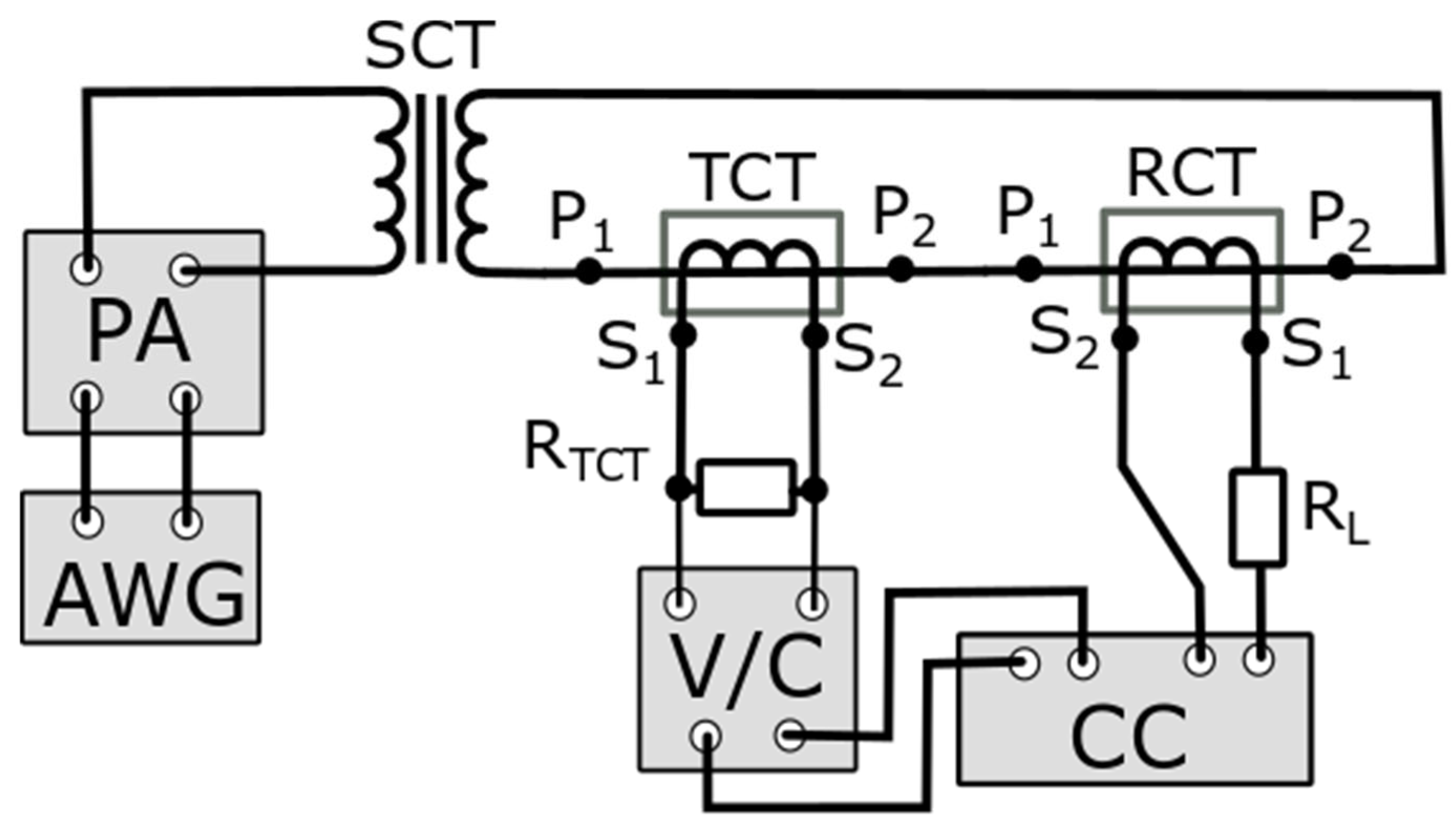
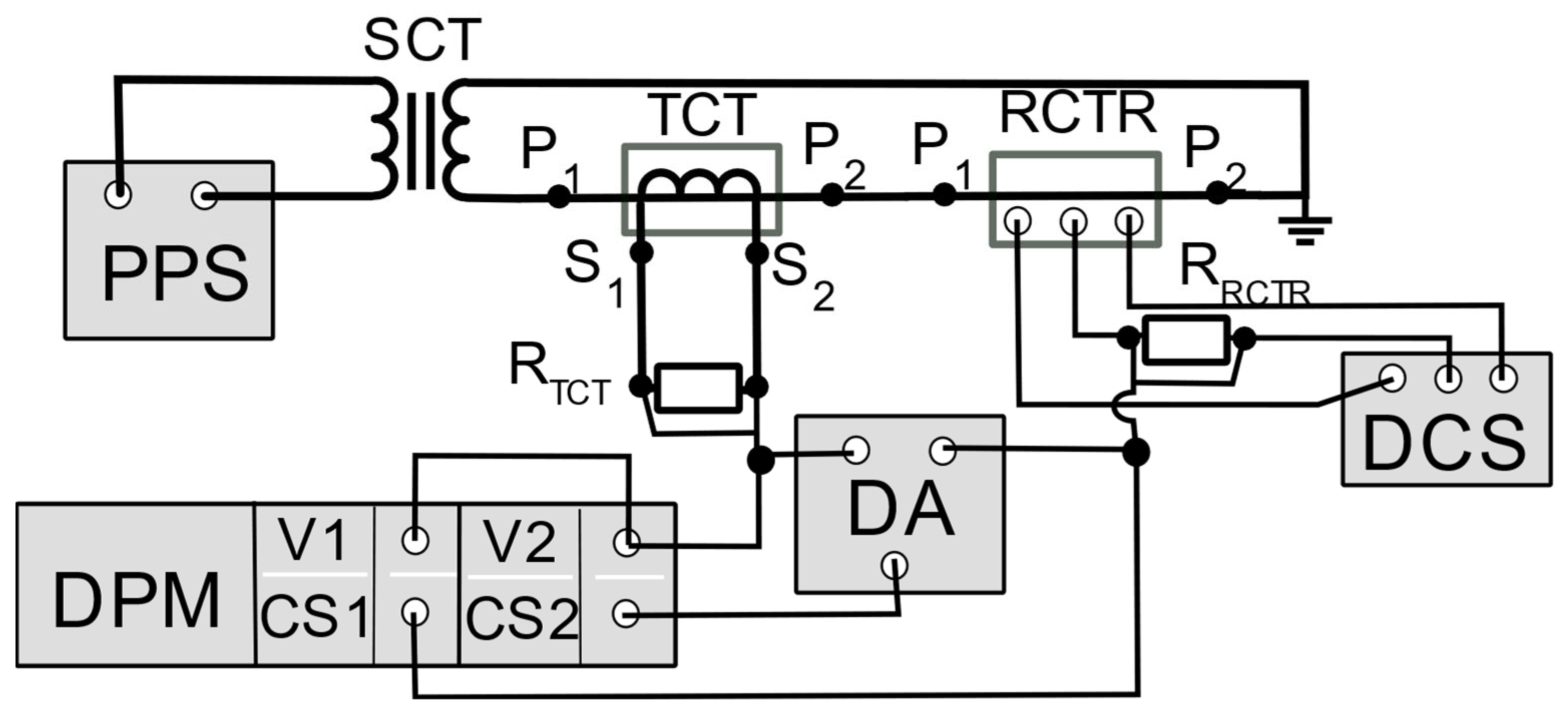
5. Measuring Setups for Evaluation of the Transformation Accuracy of Distorted Currents by Inductive CTs

To better understand the background of this study at the beginning, the ideas of the measuring setups to test the transformation accuracy of distorted current presented in standard IEC 61869-6 for the low-power instrument transformers are discussed. There are three proposals for current transformers that may also be at least partially adopted to conventional instrument transformers. The first measurement setup for analogue accuracy measurement of the current transformer is presented in Figure 8.
The purpose of the AWG and PA is to supply the measurement setup. This enables the possibility of generating a distorted voltage to obtain the distorted current with an adjustable level of harmonics and their phase angle in relation to the fundamental component. The SCT is used to step up the current from the PA to obtain its required RMS value for a given tested CT, taking into consideration its rated primary current. The RX shunt is used to convert the output voltage of RCT to the output voltage of the TCT. The core of this idea lies in the applied measuring equipment. In this case, the LiA is used. Therefore, the voltage may be measured at a selectable frequency. The typical RMS value of the input voltage is 1 V. To test conventional current transformers, the current shunts at the output of RVT and TVT must be used. It is required to obtain the same rated voltage for comparison, taking into consideration that it may not exceed 1 V RMS. Moreover, the current shunt resistance should be negligible for proper operation of the RCT and in the case of TCT, it should be considered in the selected value of resistance RL.
In Figure 9, the idea of the measurement setup for analogue accuracy measurement of the low-power current transformer with current comparator in accordance with the IEC 61869-6 is presented.
In this measurement setup, in relation to the previous one, instead of the lock-in amplifier, the current comparator CC is used. This requires the usage of an additional voltage/current converter for TCT. To test conventional current transformers, the current ratio and primary/secondary current of TCT and RCT should be the same. Then, the V/C will not be required. Unfortunately, current comparators with the possibility of detecting differences in harmonics of distorted currents are not developed for instrument transformers.
In Figure 10, the concept of the measurement setup for digital accuracy measurement of the low-power voltage transformer in accordance with IEC 61869-6 is presented.
Analogue-to-digital converters are used to obtain a digital signal from voltages on RTCT load and RX shunt. It is required that the A/Ds are synchronized. This idea is the closest to the typically used digital acquisition board and digital power meter.
Paper [19] presents an approach to determine the behavior of tested inductive CTs and VTs in steady, dynamic and transient states. The performed tests concern evaluation of the ratio error and the phase displacement at harmonic of transformed distorted current or voltage for conditions of the change of fundamental component’s amplitude and frequency, as well as the presence of the interharmonic disturbances. Moreover, the influence of the modulation of the amplitude and phase of the fundamental tone at power frequency by a sinusoidal signal and oscillatory transients composed of a fundamental tone plus a superimposed damped sinusoidal signal are considered. The measuring circuit is composed of a current generation system, a reference current-to-voltage transformer and a high precision two-channel measuring system–DAQ (Figure 11).
The value of the current error of transformation of an hk harmonic by tested CTs is calculated from the following equation:
I T C T h k = U R h k U R C T R h k U R C T R h k · 100 %
where URCTRhk—the RMS values of an hk harmonic in the output voltage of the RCTR, URhk—the RMS values of an hk harmonic in voltage of the current shunt R.
The value of the phase displacement of transformation of an hk harmonic is given by equation:
φ T C T h k = ψ U R h k ψ U R C T R h k
where ψURhk—the phase angle of an hk harmonic on current shunt R in relation to its main harmonic, ψURVDhk—the phase angle of an hk harmonic of the output voltage of RCTR in relation to its main harmonic.
The performance of accuracy tests of inductive CTs requires the generation of high RMS value distorted primary current. Therefore, the power supply must meet these requirements. The high current generation system consists of an arbitrary waveform generator equipped with two channels, a lowpass filter limiting the slew rate and the bandwidth of the generated signal, a transconductance power amplifier, and the high current transformers. The reference CT is a window-type zero-flux transformer supply with ±15 V DC. Its wide frequency metrological characteristics are verified in paper [49]. The measuring resistor connected to its secondary circuit is made of several resistors connected in parallel on the printed circuit board and a large heat sink. To determine the current error and phase displacement at harmonic from Equations (3) and (4), the RMS values of an hk harmonic in voltage of the current shunt R and the RMS values of an hk harmonic in the output voltage of the RCTR are measured by the data acquisition board.
In papers [1,2], the solution is presented, where RMS values up to 1000 A of the primary current may be obtained. The high current transformer is supplied by the audio amplifier controlled by the arbitrary waveform generator [44,50,51]. The main factors that limit the frequency range of operation of these systems are the leakage inductances of the step-up current transformer windings and its load, including the tested inductive CT. During generation of the distorted current, the increase of the higher harmonic’s frequency causes increases in the required RMS value of the suppling primary voltage of the step-up current transformer. Therefore, this voltage is limited by the electrical strength of the primary winding insulation. The differential measurement system used to determine the accuracy of inductive CTs with the step-up current transformer is presented in Figure 12.
In the differential measurement system, the value of the current error for a given hk harmonic is determined by the following equation [3,29,32,52]:
I h k = U S h k R S 2 + U D h k R D 2 2 · U S h k R S · U D h k R D · cos ϕ h k U S h k R S U S h k R S · 100 % ,
where UShk—the RMS values of an hk harmonic in the voltage of RS, UDhk—the RMS values of an hk higher harmonic in the voltage of RD, ϕhk—the phase angle of an hk harmonic in the voltage of RS in relation to the hk harmonic in the voltage of RD.
The value of the phase displacement for a given hk harmonic is determined from the equation [3,29,32,52]:
δ φ h k = a r c s i n U D h k · R S R D · U S h k · 100 % 2 I h k 2 100 % ,
In the measuring setup presented in Figure 12, the RMS values of an hk harmonic in the voltages of current shunts RS, RD and their mutual phase angle are measured by the DPM (digital power meter).
Paper [53] proposes a similar approach based on the implementation of a power amplifier, a waveform generator and a step-up current transformer, which enables us to obtain the RMS value of the primary current of tested CT equal to 100 A. It allows the generation of multisine current waveforms in which harmonic content may be adjusted. However, the operation bandwidth is limited to 1750 Hz.
The rated conditions to test the window-type inductive CTs may be obtained by application of the additional primary winding. Such an approach ensures rated ampere-turns conditions if the number of turns of this winding is equal to the number of turns of the secondary winding of the tested inductive CT (Figure 13) [3,5,6,14,52].
To determine the current error and phase displacement at harmonic from Equations (7) and (8), the RMS values of an hk harmonic in the voltages of current shunts RS, RD and their mutual phase angle are measured by the DPM. It is required that the primary winding be evenly distributed on the surface of the magnetic core.
In paper [54], the authors tested the inductive CT with the waveforms collected from the power network (Figure 14). Their accuracy is evaluated by means of the values of the composite error. To supply the measuring circuit, Fluke Transconductance 52120A is used. It enables us to obtain the RMS value of the distorted current equal to 120 A.
To determine the current error and phase displacement at harmonic from Equations (3) and (4), the RMS values of an hk harmonic in voltages of the current shunts RS and RP are measured by the data acquisition board.
In the differential method, it is possible to obtain the differential voltage proportional to the differential current between current shunts connected in the secondary circuits of the tested CT and the reference CT or the transducer [32]. This approach ensures the same required voltage ratio of the tested CT and the reference CT or transducer if their rated secondary currents for the same rated primary current are different (Figure 15).
The transformation errors of the tested CTs are calculated by measuring the composite error directly from the differential voltage between the wideband non-inductive current shunts RTCT and RRCTR. This is done by using a differential amplifier that is connected to the secondary circuits of both the reference current transducer RCTR and TCT. To calculate ratio and phase errors, the additional voltage of current shunt RRCTR and its hk harmonic phase angle in relation to the same order harmonic of the differential voltage must be measured.

6. Conclusions

There are two main techniques used to determine the transformation accuracy of VTs and CTs for sinusoidal and distorted currents or voltages. The first one is based on measurements of the secondary currents or voltage of the tested CT or VT and the reference CT/VT or the reference transducer by the digital acquisition board. Since only voltage inputs are available, additional current shunts are always required. The RMS values and phase angles of harmonics, interharmonics and subharmonics in voltages of the current shunts connected in the secondary circuits of the reference CT or reference transducer and tested CT are determined to calculate the current error and the phase displacement of their transformation. In the case of the conventional VTs, the voltage dividers are required to adjust the output of reference VT/transducer and tested VT to the permissible level of the digital acquisition board input voltage. The second idea uses a differential measuring system and a digital power meter. In this case, the secondary current of the reference CT or transducer and the differential current between the secondary windings of the tested and the reference CTs or transducer are measured. Therefore, the composite error is directly determined. In the next step, the RMS values of the secondary current harmonics are calculated to determine the values of the current error at harmonics. In the last step, from the values of composite and current errors, the values of phase displacement are calculated. The advantage of the proposed solution—the differential method—is that for the same measuring apparatus used, it always ensures lower measurement uncertainty than obtained in the measuring system where the comparison of two secondary currents or voltages is performed.
The tests with distorted current/voltage containing the primary component and one higher frequency harmonic are reliable. Only in the case of the inductive CTs may the results be influenced by the 3rd higher harmonic. Moreover, in all cases, the phase angle of the higher harmonic in relation to the fundamental harmonic in the distorted primary current/voltage has considerable influence on the values of current/voltage errors and phase displacements for the low order higher harmonics up to the frequency 500 Hz.
If the power factor of the CT secondary winding load is equal to 0.8 ind. instead of 1, a significant increase in the values of current error and phase displacement is observed. In the range of the low order higher harmonics, the self-generation phenomenon is more intensive as the secondary voltage increases with frequency, especially for higher currents and load. The transformation accuracy of higher frequency components of the distorted current is also deteriorated, due to the increase of the secondary winding load. In the case of the inductive VTs, a load power factor equal to 0.8 is more advantageous than 1.
It results from the presented review that specific measuring methods and systems should be defined in the standards IEEE and IEC. Moreover, to properly address the power quality issues, it is recommended to introduce mandatory requirements for transformation accuracy of higher harmonics by inductive instrument transformers.

Author Contributions

Conceptualization, M.K. and E.S.; methodology, M.K. and E.S.; validation, M.K. and E.S. formal analysis, M.K. and E.S.; investigation, M.K. and E.S.; resources, M.K. and E.S.; data curation, M.K. and E.S.; writing—original draft preparation, M.K. and E.S.; writing—review and editing, M.K. and E.S.; visualization, E.S.; supervision, M.K. All authors have read and agreed to the published version of the manuscript.

Funding

This research received no external funding.

Institutional Review Board Statement

Not applicable.

Informed Consent Statement

Not applicable.

Data Availability Statement

Not applicable.

Conflicts of Interest

The authors declare no conflict of interest.

Abbreviations

ψURhkphase angle of an hk harmonic on current shunt R in relation to its main harmonic,
ψURVDhkphase angle of an hk harmonic of the output voltage of RVD in relation to its main harmonic,
ψURVDhkphase angle of an hk harmonic of the output voltage of RCTR in relation to its main harmonic,
ψUVDhkphase angle of an hk harmonic on the secondary winding of TVT in relation to its main harmonic,
A/Danalogue-to-digital converter,
AWGarbitrary waveform generator,
BFFblocking filter of fundamental harmonic,
BFHblocking filter of higher harmonic,
CCcurrent comparator,
CVDcapacitor voltage divider,
DAdifferential amplifier,
DAQdata acquisition board,
DCSdirect current supply,
DPMdigital power meter,
fhfrequency of higher harmonic
i2instantaneous value of the tested CT secondary current;
i2rinstantaneous value of the RCT secondary current,
iDinstantaneous value of the differential current between the TCT and RCT secondary currents,
LFPlow pass filter,
LiAlock-in amplifier,
MEmeasuring equipment (class A power quality meter),
PApower amplifier,
PCpersonal computer,
PFFpass filter for fundamental harmonic,
PFHpass filter for higher harmonic,
RCTreference current transformer,
RCTRreference current transducer,
Rcurrent shunt,
RDcurrent shunt used to measure instantaneous value of the differential current,
RLload of secondary winding,
RScurrent shunt used to measure the instantaneous value of RCT secondary current,
RTCTrated load of the secondary winding of the TCT,
RTVTrated load of the secondary winding of the TVT,
RVDreference voltage divider,
RVTreference voltage transformer,
Rxshunt used to adjust the voltage at the input of the LiA,
SCTstep-up current transformer,
SFHsource of fundamental harmonic,
SVTstep-up voltage transformer,
TAtransconductance amplifier,
TCTtested current transformer,
TVTtested voltage transformer,
UDAhkRMS values of an hk higher harmonic in the output voltage of the DA,
URCTRhkRMS values of an hk harmonic in the output voltage of the RCTR,
URhkRMS values of an hk harmonic in current shunt R,
URVDhkRMS values of an hk harmonic in the output voltage of the RVD,
UVDhkRMS values of an hk harmonic in the output voltage of the RVD,
V/Cvoltage/current converter,
VAvoltage amplifier,
φRVDDAhkphase angle of an hk harmonic in the output voltage of the DA in relation to the hk harmonic in the reference voltage from the RVD

References

  1. Kaczmarek, M.L.; Stano, E. Application of the inductive high current testing transformer for supplying of the measuring circuit with distorted current. IET Electr. Power Appl. 2019, 13, 1310–1317. [Google Scholar] [CrossRef]
  2. Kaczmarek, M.; Kaczmarek, P.; Stano, E. The Performance of the High-Current Transformer during Operation in the Wide Frequencies Range. Energies 2022, 15, 7208. [Google Scholar] [CrossRef]
  3. Stano, E.; Kaczmarek, M. Wideband self-calibration method of inductive cts and verification of determined values of current and phase errors at harmonics for transformation of distorted current. Sensors 2020, 20, 2167. [Google Scholar] [CrossRef]
  4. Stano, E.; Kaczmarek, P.; Kaczmarek, M. Understanding the Frequency Characteristics of Current Error and Phase Displacement of the Corrected Inductive Current Transformer. Energies 2022, 15, 5436. [Google Scholar] [CrossRef]
  5. Stano, E.; Kaczmarek, P.; Kaczmarek, M. Why Should We Test the Wideband Transformation Accuracy of Inductive Current Transformers? Energies 2022, 15, 5737. [Google Scholar] [CrossRef]
  6. Kaczmarek, M.; Kaczmarek, P.; Stano, E. The Effect of the Load Power Factor of the Inductive CTs Secondary Winding on Its Distorted Current’s Harmonics Transformation Accuracy. Energies 2022, 15, 6258. [Google Scholar] [CrossRef]
  7. Kaczmarek, M.; Kaczmarek, P.; Stano, E. Evaluation of the Current Shunt Influence on the Determined Wideband Accuracy of Inductive Current Transformers. Energies 2022, 15, 6840. [Google Scholar] [CrossRef]
  8. Stano, E. The Method to Determine the Turns Ratio Correction of the Inductive Current Transformer. Energies 2021, 14, 8602. [Google Scholar] [CrossRef]
  9. Mingotti, A.; Peretto, L.; Tinarelli, R. A Smart Frequency Domain-Based Modeling Procedure of Rogowski Coil for Power Systems Applications. IEEE Trans. Instrum. Meas. 2020, 69, 6748–6755. [Google Scholar] [CrossRef]
  10. Kaczmarek, M.; Szczęsny, A.; Stano, E. Operation of the Electronic Current Transformer for Transformation of Distorted Current Higher Harmonics. Energies 2022, 15, 4368. [Google Scholar] [CrossRef]
  11. Bassan, F.R.; Rosolem, J.B.; Floridia, C.; Aires, B.N.; Peres, R.; Aprea, J.F.; Nascimento, C.A.M.; Fruett, F. Power-over-fiber LPIT for voltage and current measurements in the medium voltage distribution networks. Sensors 2021, 21, 547. [Google Scholar] [CrossRef]
  12. Mingotti, A.; Peretto, L.; Tinarelli, R.; Angioni, A.; Monti, A.; Ponci, F. A simple calibration procedure for an LPIT plus PMU system under off-nominal conditions. Energies 2019, 12, 4645. [Google Scholar] [CrossRef]
  13. Mingotti, A.; Costa, F.; Peretto, L.; Tinarelli, R. Accuracy Type Test for Rogowski Coils Subjected to Distorted Signals, Temperature, Humidity, and Position Variations. Sensors 2022, 22, 1397. [Google Scholar] [CrossRef] [PubMed]
  14. Cataliotti, A.; Cosentino, V.; Crotti, G.; Giordano, D.; Modarres, M.; Di Cara, D.; Tinè, G.; Gallo, D.; Landi, C.; Luiso, M. Metrological performances of voltage and current instrument transformers in harmonics measurements. In Proceedings of the I2MTC 2018—2018 IEEE International Instrumentation and Measurement Technology Conference: Discovering New Horizons in Instrumentation and Measurement, Houston, TX, USA, 14–17 May 2018; pp. 1–6. [Google Scholar]
  15. Crotti, G.; D’Avanzo, G.; Letizia, P.S.; Luiso, M. Measuring Harmonics with Inductive Voltage Transformers in Presence of Subharmonics. IEEE Trans. Instrum. Meas. 2021, 70, 1–13. [Google Scholar] [CrossRef]
  16. Kaczmarek, M.; Stano, E. Why should we test the wideband transformation accuracy of medium voltage inductive voltage transformers? Energies 2021, 14, 4432. [Google Scholar] [CrossRef]
  17. Crotti, G.; D’Avanzo, G.; Giordano, D.; Letizia, P.S.; Luiso, M. Extended SINDICOMP: Characterizing MV Voltage Transformers with Sine Waves. Energies 2021, 14, 1715. [Google Scholar] [CrossRef]
  18. Letizia, P.S.; Signorino, D.; Crotti, G. Impact of DC Transient Disturbances on Harmonic Performance of Voltage Transformers for AC Railway Applications. Sensors 2022, 22, 2270. [Google Scholar] [CrossRef]
  19. Crotti, G.; Chen, Y.; Çayci, H.; D’Avanzo, G.; Landi, C.; Letizia, P.S.; Luiso, M.; Mohns, E.; Muñoz, F.; Styblikova, R.; et al. How Instrument Transformers Influence Power Quality Measurements: A Proposal of Accuracy Verification Tests. Sensors 2022, 22, 5847. [Google Scholar] [CrossRef]
  20. Kaczmarek, M.; Stano, E. Measuring system for testing the transformation accuracy of harmonics of distorted voltage by medium voltage instrument transformers. Measurement 2021, 181, 109628. [Google Scholar] [CrossRef]
  21. Faifer, M.; Laurano, C.; Ottoboni, R.; Toscani, S.; Zanoni, M.; Crotti, G.; Giordano, D.; Barbieri, L.; Gondola, M.; Mazza, P. Overcoming Frequency Response Measurements of Voltage Transformers: An Approach Based on Quasi-Sinusoidal Volterra Models. IEEE Trans. Instrum. Meas. 2019, 68, 2800–2807. [Google Scholar] [CrossRef]
  22. Castello, P.; Laurano, C.; Muscas, C.; Pegoraro, P.A.; Toscani, S.; Zanoni, M. Harmonic Synchrophasors Measurement Algorithms with Embedded Compensation of Voltage Transformer Frequency Response. IEEE Trans. Instrum. Meas. 2021, 70, 9001310. [Google Scholar] [CrossRef]
  23. Faifer, M.; Laurano, C.; Ottoboni, R.; Toscani, S.; Zanoni, M. Harmonic Distortion Compensation in Voltage Transformers for Improved Power Quality Measurements. IEEE Trans. Instrum. Meas. 2019, 68, 3823–3830. [Google Scholar] [CrossRef]
  24. Draxler, K.; Styblikova, R. Using instrument transformers in a wider frequency range. In Proceedings of the Conference Record—IEEE Instrumentation and Measurement Technology Conference, Hangzhou, China, 10–12 May 2011; pp. 1207–1210. [Google Scholar]
  25. Draxler, K.; Styblikova, R. Calibration of instrument current transformers at low currents using lock-in amplifier. In Proceedings of the International Conference on Applied Electronics (AE), Pilsen, Czech Republic, 5–6 September 2017; pp. 18–21. [Google Scholar] [CrossRef]
  26. Bauer, J.; Ripka, P.; Draxler, K.; Styblikova, R. Demagnetization of current transformers using PWM burden. IEEE Trans. Magn. 2015, 51, 1–4. [Google Scholar] [CrossRef]
  27. Hong, Y.Y.; Wei, D.W. Compensation of distorted secondary current caused by saturation and remanence in a current transformer. IEEE Trans. Power Deliv. 2010, 25, 47–54. [Google Scholar] [CrossRef]
  28. Draxler, K.; Hlavacek, J.; Styblikova, R. Calibration of Instrument Current Transformer Test Sets. In Proceedings of the International Conference on Applied Electronics (AE), Pilsen, Czech Republic, 10–11 September 2019. [Google Scholar] [CrossRef]
  29. Kaczmarek, M.; Stano, E. The Influence of the 3rd Harmonic of the Distorted Primary Current on the Self-Generation of the Inductive Current Transformers. IEEE Access 2022, 10, 55876–55887. [Google Scholar] [CrossRef]
  30. Filipović-Grčić, D.; Filipović-Grčić, B.; Krajtner, D. Frequency response and harmonic distortion testing of inductive voltage transformer used for power quality measurements. Procedia Eng. 2017, 202, 159–167. [Google Scholar] [CrossRef]
  31. Kaczmarek, M.; Stano, E. Application of the Sinusoidal Voltage for Detection of the Resonance in Inductive Voltage Transformers. Energies 2021, 14, 7047. [Google Scholar] [CrossRef]
  32. Kaczmarek, M.; Stano, E. Proposal for extension of routine tests of the inductive current transformers to evaluation of transformation accuracy of higher harmonics. Int. J. Electr. Power Energy Syst. 2019, 113, 842–849. [Google Scholar] [CrossRef]
  33. Crotti, G.; Giordano, D.; D’Avanzo, G.; Letizia, P.S.; Luiso, M. A New Industry-Oriented Technique for the Wideband Characterization of Voltage Transformers. Meas. J. Int. Meas. Confed. 2021, 182, 109674. [Google Scholar] [CrossRef]
  34. IEC 61869-1; Ins. Trans.—General Requirements. IEC: Geneva, Switzerland, 2007.
  35. IEC 61869-3; Ins. Trans.—Additional Requirements for Voltage Transformers. IEC: Geneva, Switzerland, 2011.
  36. IEC 61869-2; Ins. Trans.—Additional Requirements for Current Transformers. IEC: Geneva, Switzerland, 2012.
  37. IEEE C57.13-2016; IEEE Standard Requirements for Instrument Transformers. IEEE: Piscataway, NJ, USA, 2016.
  38. IEC 61869-6; Inst. Transf.—Additional General Requirements for Low-Power Instrument Transformers. IEC: Geneva, Switzerland, 2016.
  39. Cataliotti, A.; Cosentino, V.; Crotti, G.; Femine, A.D.; Di Cara, D.; Gallo, D.; Giordano, D.; Landi, C.; Luiso, M.; Modarres, M.; et al. Compensation of Nonlinearity of Voltage and Current Instrument Transformers. IEEE Trans. Instrum. Meas. 2019, 68, 1322–1332. [Google Scholar] [CrossRef]
  40. IEC 61869-103; Inst. Transf.—The Use of Instrument Transformers for Power Quality Measurement. IEC: Geneva, Switzerland, 2010.
  41. IEC 61869-11; Ins. Trans.—Additional Requirements for Low Power Passive Voltage Transformers. IEC: Geneva, Switzerland, 2017.
  42. Kaczmarek, M. Two Channels Opto-Isolation Circuit for Measurements of the Differential Voltage of Voltage Transformers and Dividers. Energies 2022, 15, 2694. [Google Scholar] [CrossRef]
  43. Kaczmarek, M. Development and application of the differential voltage to single-ended voltage converter to determine the composite error of voltage transformers and dividers for transformation of sinusoidal and distorted voltages. Meas. J. Int. Meas. Confed. 2017, 101, 53–61. [Google Scholar] [CrossRef]
  44. Mohns, E.; Fricke, S.; Pauling, F. An AC power amplifier for testing instrument transformer test equipment. In Proceedings of the Conference on Precision Electromagnetic Measurements (CPEM 2016), Ottawa, ON, Canada, 10–15 July 2016; pp. 5–6. [Google Scholar] [CrossRef]
  45. Crotti, G.; D’Avanzo, G.; Landi, C.; Letizia, P.S.; Luiso, M. Evaluation of Voltage Transformers’ Accuracy in Harmonic and Interharmonic Measurement. IEEE Open J. Instrum. Meas. 2022, 1, 1–10. [Google Scholar] [CrossRef]
  46. Crotti, G.; Gallo, D.; Giordano, D.; Landi, C.; Luiso, M.; Modarres, M.; Zucca, M. Frequency Compliance of MV Voltage Sensors for Smart Grid Application. IEEE Sens. J. 2017, 17, 7621–7629. [Google Scholar] [CrossRef]
  47. Faifer, M.; Laurano, C.; Ottoboni, R.; Toscani, S.; Zanoni, M. Characterization of voltage instrument transformers under nonsinusoidal conditions based on the best linear approximation. IEEE Trans. Instrum. Meas. 2018, 67, 2392–2400. [Google Scholar] [CrossRef]
  48. Faifer, M.; Ferrero, A.; Laurano, C.; Ottoboni, R.; Toscani, S.; Zanoni, M. An Innovative Approach to Express Uncertainty Introduced by Voltage Transformers. IEEE Trans. Instrum. Meas. 2020, 69, 6696–6703. [Google Scholar] [CrossRef]
  49. Chen, Y.; Mohns, E.; Seckelmann, M.; De Rose, S. Traceable calibration system for non-conventional current sensors with analogue or digital output. In Proceedings of the AMPS 2021—2021 11th IEEE International Workshop on Applied Measurements for Power Systems, Cagliari, Italy, 29 September–1 October 2021. [Google Scholar]
  50. Brodecki, D.; Stano, E.; Andrychowicz, M.; Kaczmarek, P. Emc of wideband power sources. Energies 2021, 14, 1457. [Google Scholar] [CrossRef]
  51. Kaczmarek, M.; Kaczmarek, P. Comparison of the wideband power sources used to supply step-up current transformers for generation of distorted currents. Energies 2020, 13, 1849. [Google Scholar] [CrossRef]
  52. Kaczmarek, M.; Stano, E. Nonlinearity of Magnetic Core in Evaluation of Current and Phase Errors of Transformation of Higher Harmonics of Distorted Current by Inductive Current Transformers. IEEE Access 2020, 8, 118885–118898. [Google Scholar] [CrossRef]
  53. Cristaldi, L.; Faifer, M.; Laurano, C.; Ottoboni, R.; Toscani, S.; Zanoni, M. A Low-Cost Generator for Testing and Calibrating Current Transformers. IEEE Trans. Instrum. Meas. 2019, 68, 2792–2799. [Google Scholar] [CrossRef]
  54. Mingotti, A.; Peretto, L.; Bartolomei, L.; Cavaliere, D.; Tinarelli, R. Are inductive current transformers performance really affected by actual distorted network conditions? An experimental case study. Sensors 2020, 20, 927. [Google Scholar] [CrossRef] [PubMed]
Figure 1. Measurement setup for analogue accuracy measurement of voltage transformer with a lock-in amplifier, self-prepared in accordance with IEC 61869-6 [38]. Where: RVT—reference voltage transformer, PA–power amplifier, AWG—arbitrary waveform generator, SVT—step-up voltage transformer, TVT—tested voltage transformer (A, B—terminal of the primary winding, a, b—terminals of the secondary winding), LiA—lock-in amplifier, RTVT—rated load of the secondary winding of the TVT, RL—load of secondary winding, RX—shunt used to adjust the voltage at the input of the LiA.
Energies 16 04360 g001
Figure 2. Measurement setup for analogue accuracy measurement of voltage transformer with a current comparator, self-prepared in accordance with IEC 61869-6 [38]. Where: V/C—voltage/current converter, CC—current comparator.
Energies 16 04360 g002
Figure 3. Measurement setup for digital accuracy measurement of voltage transformer self-prepared in accordance with IEC 61869-6 [38]. Where: A/D—analogue-to-digital converter, PC—personal computer (synchronization source for A/Ds).
Energies 16 04360 g003
Figure 4. Differential measuring system for evaluation of the transformation accuracy of distorted voltage by the inductive VTs self-prepared in accordance with the papers [16,20,31]. Where: RVD—reference voltage divider, DPM—digital power meter, DA—differential amplifier.
Energies 16 04360 g004
Figure 5. Measuring system used to detect the resonance frequencies of the inductive VTs self-prepared in accordance with the paper [31].
Energies 16 04360 g005
Figure 6. Measuring setup with two sources and with compensation self-prepared in accordance with the paper [30]. Where: SFH—source of fundamental harmonic, PFF—pass filter for fundamental harmonic, BFH—blocking filter of the higher harmonic, PFH—pass filter for higher harmonic, BFF—blocking filter of fundamental harmonic, CVD—capacitor voltage divider, ME—measuring equipment (class A power quality meter).
Energies 16 04360 g006
Figure 7. Measuring setup with data acquisition system self-prepared in accordance with paper [45]. Where: VA—voltage amplifier, DAQ—data acquisition board.
Energies 16 04360 g007
Figure 8. Measurement setup for analogue accuracy measurement of the current transformer with a lock-in amplifier, self-prepared in accordance with IEC 61869-6 [38]. Where: SCT—step-up current transformer, TCT—tested current transformer, RCT—reference current transformer, RTCT—rated load of the secondary winding of the TCT.
Energies 16 04360 g008
Figure 9. Measurement setup for analogue accuracy measurement of current transformer with a current comparator, self-prepared in accordance with IEC 61869-6 [38].
Energies 16 04360 g009
Figure 10. Measurement setup for digital accuracy measurement of current transformer self-prepared in accordance with IEC 61869-6 [38].
Energies 16 04360 g010
Figure 11. Generation and measurement setup for the tested current transformers self-prepared in accordance with paper [19]. Where: LFP—low pass filter, RCTR—reference current transducer, R—current shunt.
Energies 16 04360 g011
Figure 12. Differential measurement system used to determine the accuracy of inductive CTs with the step-up current transformer self-prepared in accordance with the papers [1,2]. Where: RD—current shunt used to measure instantaneous value of the differential current, RS—current shunt used to measure the instantaneous value of RCTs secondary current, i2—instantaneous value of the tested CTs secondary current, i2r—instantaneous value of the RCTs secondary current, iD—instantaneous value of the differential current between the TCT and RCT secondary currents.
Energies 16 04360 g012
Figure 13. Measurement setup used to determine the accuracy of inductive CT in its ampere-turns conditions self-prepared in accordance with the papers [3,5,6,14,52].
Energies 16 04360 g013
Figure 14. Measurement setup used for evaluating the accuracy of the tested CT self-prepared in accordance with paper [54]. Where TA—transconductance amplifier.
Energies 16 04360 g014
Figure 15. Measurement setup used for evaluating the accuracy of the tested CT with utilization of the reference current transducer and current ratio adjustment self-prepared in accordance with the paper [32]. Where: DCS-direct current supply.
Energies 16 04360 g015
Table 1. Proposed limiting values of current error and phase displacement at harmonics for inductive CTs.
Accuracy ClassCurrent Error [%]Phase Displacement [°]
0.1 ≤ fh < 11 ≤ fh < 1.51.5 ≤ fh < 30.1 ≤ fh < 11 ≤ fh < 1.51.5 ≤ fh < 3
0.1±0.4±0.8±1.2±0.25±0.5±1.0
0.2; 0.2 S±0.75±1.5±3±0.5±1.0±2.0
0.5; 0.5 S±1.5±3±6±1.5±3.0±6.0
where: fh—frequency of higher harmonic.
Table 2. Proposed limiting values of voltage error and phase displacement at harmonics for inductive VTs.
Accuracy ClassVoltage Error [%]Phase Displacement [°]
0.1 ≤ fh < 11 ≤ fh < 1.51.5 ≤ fh < 30.1 ≤ fh < 11 ≤ fh < 1.51.5 ≤ fh < 3
0.1±0.1±0.2±0.4±0.25±0.5±1.0
0.2±0.2±0.4±0.8±0.5±1.0±2.0
0.5±0.5±1±2±1.5±3.0±6.0
Disclaimer/Publisher’s Note: The statements, opinions and data contained in all publications are solely those of the individual author(s) and contributor(s) and not of MDPI and/or the editor(s). MDPI and/or the editor(s) disclaim responsibility for any injury to people or property resulting from any ideas, methods, instructions or products referred to in the content.

