Review

Technical Scheme and Application Prospects of Oil Shale In Situ Conversion: A Review of Current Status

1
State Key Laboratory of Organic Geochemistry, Guangzhou Institute of Geochemistry, Chinese Academy of Sciences, Guangzhou 510640, China
2
University of Chinese Academy of Sciences, Beijing 100049, China
3
CAS Center for Excellence in Deep Earth Science, Guangzhou 510640, China
*
Authors to whom correspondence should be addressed.
Energies 2023, 16(11), 4386; https://doi.org/10.3390/en16114386
Submission received: 29 March 2023 / Revised: 24 May 2023 / Accepted: 26 May 2023 / Published: 29 May 2023
(This article belongs to the Special Issue Hydrocarbon Accumulation Process and Mechanism)

Abstract

:
Petroleum was the most-consumed energy source in the world during the past century. With the continuous global consumption of conventional oil, shale oil is known as a new growth point in oil production capacity. However, medium–low mature shale oil needs to be exploited after in situ conversion due to the higher viscosity of oil and the lower permeability of shale. This paper summarizes previous studies on the process of kerogen cracking to generate oil and gas, and the development of micropore structures and fractures in organic-rich shale formations during in situ conversion. The results show that the temperature of kerogen cracking to generate oil and gas is generally 300–450 °C during the oil shale in situ conversion process (ICP). In addition, a large number of microscale pores and fractures are formed in oil shale formation, which forms a connecting channel and improves the permeability of the oil shale formation. In addition, the principles and the latest technical scheme of ICP, namely, conduction heating, convection heating, reaction-heat heating, and radiation heating, are introduced in detail. Meanwhile, this paper discusses the influence of the heating mode, formation conditions, the distribution pattern of wells, and catalysts on the energy consumption of ICP technology in the process of oil shale in situ conversion. Lastly, a fine description of the hydrocarbon generation process of the target formation, the development of new and efficient catalysts, and the support of carbon capture and storage in depleted organic-rich shale formations after in situ conversion are important for improving the future engineering efficiency of ICP.

1. Introduction

The latest energy outlook of the EIA (2022) indicates that petroleum will remain the most-consumed energy source all the way through to 2050. With increasing petroleum consumption, shale oil may become an important global source of energy, and one of the frontiers and bright spots of the petroleum industry [1,2,3]. It is estimated that shale-oil reserves are as high as 670 billion tons, which is four times the global recoverable oil reserves (approximately 170 billion tons) [4]. According to thermal evolution maturity, shale-oil resources are divided into low–medium mature shale oil and medium–high mature shale oil [1,2,3,5]. Medium–high mature shale oil can generally be exploited directly through hydraulic fracturing due to its good fluidity, while medium–low mature shale oil needs to be exploited after in situ conversion due to the higher viscosity of oil and the lower permeability of shale. China is one of the most successful countries in the world in achieving the commercial-scale exploitation of continental shale oil. In 2021, its production of medium–high mature continental shale oil was approximately 272.3 × 10⁴ t [3]. The total amount of shale-oil resources that can be generated from medium–low mature shale oil in China through in situ conversion is 1016.2 × 108 t (oil equivalent), including 704.2 × 10⁸ t of liquid hydrocarbon and 312 × 108 t (oil equivalent) of gaseous hydrocarbon, which is far greater than the total geological resources of medium-high mature continental shale oil ((130~163) × 108 t) [1,2,3,6]. Therefore, shale oil developed from medium–low mature shale via in situ conversion has significant oil and gas resources, and may become an important growth point of the petroleum industry.
Organic-rich shale, including oil shale, is a fine-grained sedimentary rock that contains a great quantity of kerogen [2]. When the maturity of organic-rich shale is low, most of the organic substances are kerogen, which is insoluble in traditional organic solvents; when the maturity of the shale is high, kerogen is cracked to produce oil or natural gas [7]. Therefore, the acquisition of medium–low mature shale-oil resources requires the artificial pyrolysis of kerogen to convert it into gaseous or liquid resources. Kerogen cracking to generate oil and gas is a complicated chemical process that is mainly affected by kinetic effects [8,9]. A large number of pyrolytic experiments have been conducted in closed, semiclosed, or open systems to investigate the hydrocarbon generation process and calculate the kinetic parameters [7,10,11,12,13,14,15,16]. These studies indicated that petroleum products generated from organic-rich shale depend on the features of shale and pyrolytic conditions. This means that petroleum products during organic-rich shale in situ conversion can be predicted under certain pyrolytic conditions after the appropriate kinetic model is established.
In a natural state, medium–low mature organic-rich shale is dense and impermeable, and there are few naturally developed pores and fractures [17,18]. However, the micropore structure and permeability of these shales significantly change during in situ shale conversion, which is crucial to the heat conduction and flow of oil and gas [17,18]. Therefore, it is very important to determine the evolutionary pattern of the pore structure, and form a mathematical model for medium–low mature organic-rich shale in situ conversion (ICP) [19,20].
There are various methods for heating shales during in situ conversion processes. According to their heating principle, they can be divided into four types: conductive heating, convection heating, reaction heating, and radiation heating (Table 1). There is no doubt that shale-oil exploitation technology after in situ conversion is feasible [21,22,23,24,25,26,27]. However, because the in situ conversion of oil shale oil is a very energy-consuming process, the heating mode, distribution pattern of wells, and catalysts can significantly affect the economy of oil shale in situ conversion. In the present study, the principle and technique actuality of oil shale in situ conversion, the changes in petroleum products, and the evolution of the micropore structure and fracture characteristics during low-maturity organic-rich shale in situ conversion are summarized.

2. Pyrolytic Process of Organic-Rich Shale

According to the reported in situ conversion experiments of organic-rich shale, the thermogravimetric (TG) curve and differential thermogravimetric (DTG) curve share similarities [20,25,49,50,51,52,53]. On the basis of the TG and DTG curves (Figure 1), organic-rich shale in situ conversion can be divided into three stages: low-, medium-, and high-temperature. Although there are different types of shale and different heating rates, the temperature threshold of the three zones has slight changes, each stage has the same change trend, and the physicochemical reaction process and mechanism of each stage are also very similar [25,53].

2.1. Low-Temperature Stage

The low-temperature stage ranges from the beginning of heating to the initial cracking temperature (ICT) when kerogen in the shale begins to pyrolyze [25,49,50]. The value of the initial critical temperature is generally approximately 300 °C [44,50,52,53]. At the low-temperature stage, water inside the shale vaporizes, and little adsorbed gas escapes. Before 200 °C, the reduction in shale mass is mainly due to the evaporation of free water and adsorbed water. Between 200 and 300 °C, the reduction in shale mass is mainly due to the evaporation of crystal water in minerals. In this process, the transformation of water into gas requires considerable energy, which reduces the heating efficiency [20]. Meanwhile, inorganic minerals undergo a certain deformation and increase the pore volume under thermal expansion [52,54]. Therefore, the low-temperature stage is mainly thermophysical evolution, and there is essentially no oil and gas generation.

2.2. Medium-Temperature Stage

The medium-temperature stage covers the range from organic-matter pyrolysis at ICT to the final cracking temperature (FCT) (approximately 450 °C), when the kerogen in the shale was completely depleted [20,25,49,50]. During this stage, a great quantity of shale oil and gas is generated.
To explore the generation process of oil and gas, the evolution of kerogen pyrolytic products in a closed system was studied in detail [7,12,14,54]. In general, pyrolytic products generated from kerogen can be described as follows [7,10,11,12,13,14,15,16]:
Kerogen→C1−5 + Non−HC gases + C6−14 + C15+ + NSOs + solid residue
NSOs→C1−5 + Non−HC gases + C6−14 + C15+ + solid residue
C15+→C1−5 + C6−14 + solid residue
C6−14→C1−5 + solid residue
C2−5→C1 + solid residue
Figure 2 shows the change in the relative mass content of different products during the nonisothermal pyrolysis of a typical kerogen [7]. At the early mature stage (Easy%Ro < 0.80%), NSO content visibly increases and is higher than the generated HC component. This result indicates that, at the early stage of primary kerogen cracking, NSO is mainly produced, followed by C15+, C6−14, and less gas. When Easy%Ro > 0.90%, the content of NSO decreases significantly, while amounts of C15+, C6−14, and C1−5 components continuously increase. The content of C15+ and C6−14 components reaches the maximum when Easy%Ro is approximately 1.0% and 1.4%, respectively. Therefore, the content and composition of petroleum products constantly change during pyrolysis. This shows that, in the process of organic-rich shale in situ conversion, we should select the right time to collect oil and gas in order to obtain products with the best economic benefits. The factors affecting the efficiency of in situ conversion mainly include the final pyrolytic temperature, heating rate, and constant temperature time [7,55]. From the experimental simulation and field experiments, it can be concluded that the pyrolysis of kerogen has an initial temperature (ICT) regardless of what kind of shale-oil conversion technology is used [7,11,20,44,45,49,50,51,55,56,57]. Therefore, only when the temperature exceeds the ICT is the increase in heat carrier energy called effective pyrolysis energy [20]. In other words, the heating power needs to be high enough during the in situ conversion process.

2.3. High-Temperature Stage

The high-temperature stage covers the range from the end of the kerogen cracking reaction until a higher temperature is reached [20,25,49,50]. The high-temperature stage mainly involves the thermal decomposition of inorganic minerals. At the high-temperature stage, the pyrolysis of kerogen ends, some clay minerals are dehydrated, and some carbonate minerals are decomposed [25]. However, in situ organic-rich shale conversion is not heated to this temperature.

3. Evolution of Pore Structure and Fractures during Organic-Rich Shale Pyrolysis

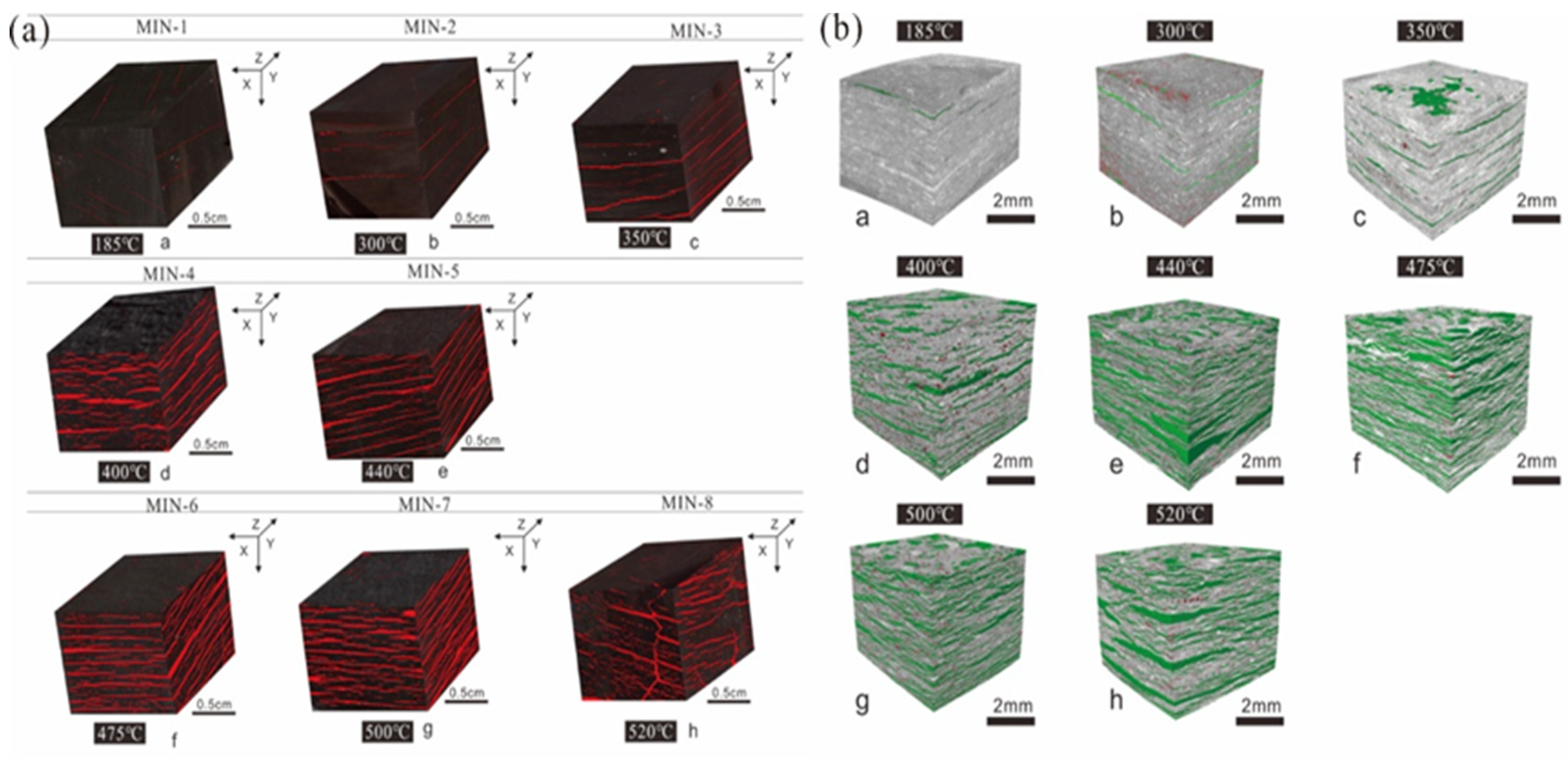
In a natural state, organic-rich shale is compact and impermeable, with almost no naturally formed pores and fractures [17,18]. This leads to a key problem in shale oil in situ conversion: how do oil and natural gas products generated by shale migrate within the shale formation? Although there are relatively mature fracturing technologies that could form artificial fractures, the economic burden is large. Oil shale has a layered structure, so hardness perpendicular to the bedding is stronger than that parallel to the bedding, and the heat transfer coefficient perpendicular to the bedding is lower than that parallel to the bedding direction [58]. This layered structure of shale provides extremely good physical conditions for horizontal fracture generation [17,18]. A large number of pores and fractures are formed during the in situ conversion process [17,18]. Therefore, generated oil and gas products can be transported to the surface through these fractures and pores. This requires a detailed study of the evolution and distribution of pore structures and fractures during in situ conversion. Niu et al. studied the evolution of pore structures and fractures during Minhe organic-rich shale pyrolysis through three-dimensional surface scanning imaging and micro-CT imaging technology [17]. They used three-dimensional surface scanning imaging to obtain the fracture evolution of Minhe shale at temperatures from 185 to 600 °C, and then used microscopic CT imaging to obtain the pore evolution (Figure 3). The study found that there were almost no fractures, and very few pores in the shale sample at the low-temperature stage. At the medium-temperature stage, fractures develop along the bedding and are uniformly distributed in the shale. The number and width of fractures increase strikingly, with a fracture width of up to 1 mm and a fracture density of over 10/cm2. Meanwhile, the porosity increases significantly and reached 30% during the pyrolytic process. At the high-temperature stage, a large number of early fractures gradually widen and extend, and partial penetrating fractures are generated that connect adjacent fractures to form a high-permeability fracture system. The total porosity at the high-temperature stage is also larger than that in other stages, increasing from 30% to 40% [17]. Many studies reported that the porosity caused by organic-rich shale in situ conversion is usually in the range of 10–50%, with an average of 36% [17,18,52,59]. The difference is related to the composition of oil shale because the pore structure is formed by removing oil, water, carbonate decomposition, and microexpansion fractures [52,60].
Many studies have also investigated the evolution of permeability during in situ organic-rich shale conversion. The evolutionary trends of permeability that is perpendicular to the shale bedding plane (PEBP) and porosity are different (Figure 4), and the correlation between porosity and permeability (PEBP) is not high. The sharp increase in porosity does not correspond to an increase in permeability, indicating that the increase in porosity has little effect on permeability, which can maintain good vertical sealing ability of the formation during the pyrolytic process. However, the formation permeability that is parallel to the shale bedding plane (PABP) is particularly important for the transportation of oil and gas. Bai et al. reported that the permeability (PABP) of Huadian organic-rich shale after pyrolysis reached 1.3 mD [18]/ Kang et al. reported that the PABP of Fushun organic-rich shale after pyrolysis reached 0.2 mD [61]. The permeability values obtained in these studies differ greatly because different examples, equipment, and experimental parameters were used, and the permeability of the samples was closely related to the confining pressure and fluid pressure. According to the ICP field test, the horizontal permeability of the core in the heating area is approximately 0.1–10 mD, and the corresponding porosity is between 15% and 25% [62].
The threshold temperature at which pores and fractures sharply increase corresponds to the ICT of kerogen pyrolysis. When the temperature exceeds the cracking temperature, kerogen begins to crack, and a great quantity of pores and fractures are produced in the skeletal structure of the shale that provide a way to transfer the generated petroleum products [60]. In conclusion, the results of the organic-rich shale pyrolysis experiment indicate that a great quantity of pores and fractures from micro to macro scales are generated during in situ conversion, which transforms organic-rich shale from almost impermeable to permeable. The above review shows that pores and fractures formed in the process of in situ conversion can support the exploitation of oil and natural gas.

4. Present Situation of In Situ Conversion Technology

4.1. In Situ Conductive Heating Technology

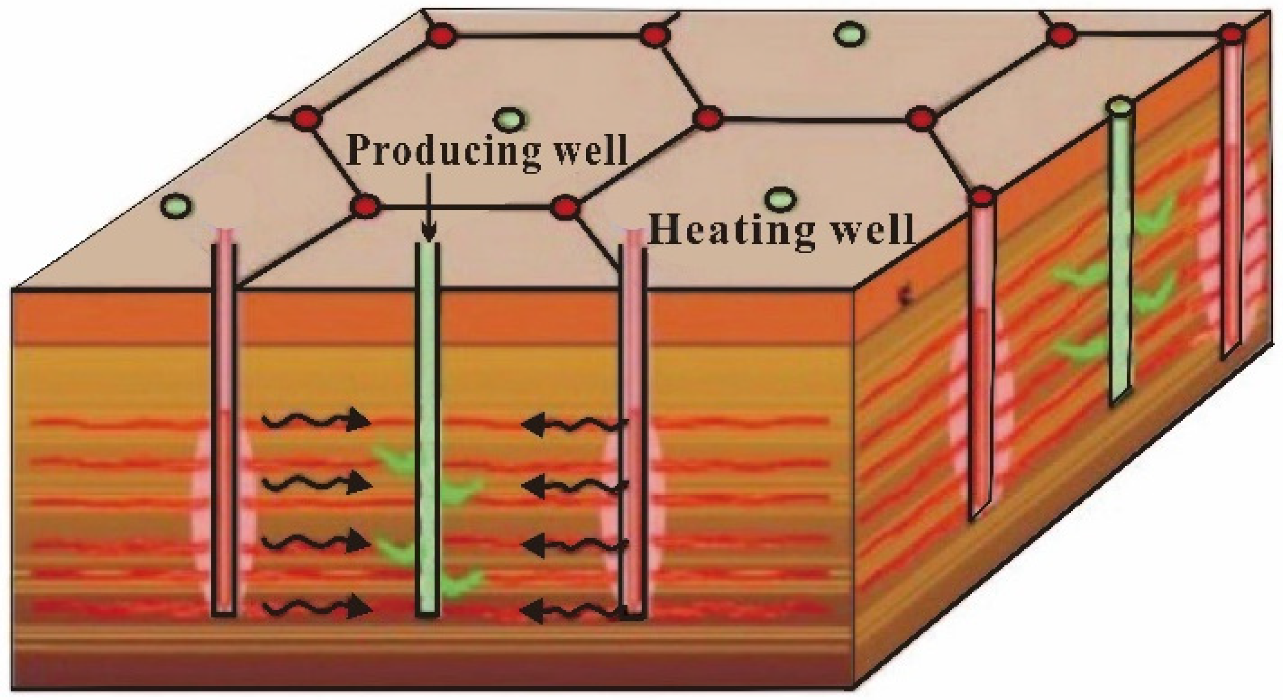
The Shell in situ conversion process (ICP) technology is currently the most mature in situ conversion technology. ICP technology consists of using an electric heater installed in a well to heat the target organic-rich shale, so that kerogen in the shale can be cracked to generate oil and gas (Figure 5). During the heating process, a great quantity of pores and fractures is produced in oil shale, forming a good horizontal transport channel that can transport petroleum products to the production wells. Shell successfully exploited high-quality shale oil in the Colorado Green River, Jordan, and the Mahogany Demonstration Project using ICP technology [19,20]. The conduction efficiency of using ICP technology alone to heat organic-rich shale formations is low, which slows down the heating rate. Generally, it takes one to two years to produce oil, and the heating process consumes a great amount of energy [28]. A variety of auxiliary processes have been developed, such as nitrogen assistance and adding a catalyst (porous silicate), which could improve the heating efficiency [14,63]. Shell also developed the freezing-wall technology to reduce the loss of heat energy caused by groundwater circulation during heating [64]. Field tests have confirmed that ICP technology is feasible and has good development prospects, but it has not been certified on a commercial scale.
The ExxonMobil ElectrofracTM technology first fractures organic-rich shale with hydraulic fracturing, fills the fracture with conductive materials to form thermal resistance, and lastly applies voltage to the resistance to make the resistance give out heat. After enough heat energy is transferred to the shale, the kerogen starts to crack and convert into shale oil and natural gas, which is produced from the production well. ElectrofracTM technology solves the problem of heating device life and increases the heating body area, but it requires a high-fracturing technology. The ElectrofracTM technology was tested in a shale-oil field in Coronay Mine, Colorado, USA in 2007, and preliminarily verified the feasibility of ElectrofracTM technology, but did not produce shale oil [29].
Independent Energy Partners (IEP) proposed a geothermic fuel cell heating technology (GFC) that uses heat generated by solid oxide fuel cells to heat organic-rich shale. Solid oxide fuel cells are installed into the target formation through a well. Heat energy released by the fuel cell heats the shale formation and promotes kerogen cracking. The produced natural gas can provide fuel to the nearby solid oxide fuel cell to ensure the continuous operation of fuel cells [30]. GFC technology requires less external energy and releases little toxic gas [31]. However, the heating efficiency of GFC technology is lower than that of the ICP technology, and the heating device is complex. The GFC technology is still at the laboratory demonstration stage.
Jilin University and the Tomsk University of Technology jointly developed a high-voltage-power frequency electric heating (HVF) technology [32]. This method consists of first using a high voltage level to cause partial discharge in the shale formation to form a plasma channel that reduces the resistance of the two electrode areas, and then electrifies the plasma channel to heat the shale formation. The heating rate of the HVF technology is very fast. In the laboratory, a 15 cm shale column was heated by HVF technology, and oil and gas could be generated within 10 min [33]. Similar to GFC technology, HVF technology is still at the stage of laboratory demonstration.
In short, due to the poor conductivity and heat transfer of organic-rich shale, conductive heating technology generally takes a long time during in situ shale conversion. In addition, only a small part of the heat energy is used for the pyrolysis of kerogen, and other heat energy is lost during the heating process. With the current price of electricity in China, the cost of electric energy consumed for calculation is higher than the value of the obtained products, and commercial exploitation cannot be carried out.

4.2. In Situ Convection Heating Technology

Another direction of in situ conversion is to inject thermal fluid into shale formations to heat the shale. Chevron first proposed Chevron’s technology for the recovery and upgrading of oil from shale (CRUSH) that uses artificial fractures to inject high-temperature fluid media (hot steam, natural gas, CO2) into organic-rich shale formations [34]. The continuous injection of high-temperature gas heats the shale formation. Chevron planned to test the feasibility of the technology in the laboratory, but the project was abandoned in 2012 [20].
The American Shale Oil Company proposed the Conduction, Convection, and Reflux (CCR) technology that uses boiling oil as a convective heating carrier, and comprehensively uses heat conduction and thermal convection to heat shale formations. CCR technology first drills a horizontal heating well and a horizontal production well into the shale, and the heating well is below the production well. The kerogen around the heating well cracks first, and the generated high-temperature gaseous hydrocarbons flow upward along the fractures in the shale, and disperse the heat into the formation [34]. Due to the decrease in international crude oil prices, research on this technology has been discontinued.
The Western Mountain Energy Company developed the in situ vapor extraction (IVE) technology [35]. IVE technology uses high-temperature gas to heat shale oil in shale formations and vaporize it, and then the gas carries the evaporated shale oil to the surface. IVE transports oil to the surface in the gas state, so that the oil and gas generated by pyrolysis can be more easily extracted. The process was initially tested in the Shannon formation of the Teapot Dome oil field in the United States. The results showed that, after 30 days of steam injection, a large number of bubbles appeared at the wellhead of the production well [20].
Kang et al. developed the in situ steam injection technology (MTI technology proposed by the Mining Technology Institute) [36,37,38]. The MTI technology consists of using multiwell hydraulic fracturing technology to connect a heat injection well with a production well, and then injects a high-temperature-superheated water steam (>550 °C) into the shale formation along the heat injection, so that the kerogen can be cracked after being heated, and oil and gas can be carried to the surface through the water steam (Figure 6). After the waste-heat recovery of the steam, gas, oil, and water are separated by the condensing system to obtain petroleum products. However, in order to prevent the loss of heating fluid, MTI has a high requirement for sealing above and below the target formation. Although the energy consumption of heating organic-rich shale with high-temperature and high-pressure N2, CO2, and hydrocarbon gases is lower than that of water steam, primitive coal energy can be used to generate high-temperature and high-pressure water steam, and the cost of coal is much lower than the cost of electricity [36]. Meanwhile, in the process of heating with water steam, high-temperature water steam can provide hydrogen for kerogen cracking, which increases the output of oil and light components [39,40]. The feasibility experiment of MTI technology was completed in the laboratory [36], and a pilot test of in situ mining is planned to be carried out in Fukang, Xinjiang.
Wang et al. developed the near-critical water (NCW) in situ conversion technology [34]. The NCW technology heats water injected underground to a near-critical or supercritical state through a downhole heater, and then uses the near-critical water as the heat transfer medium and extraction agent to heat the target formation and carry the petroleum products to the surface [35]. The process was tested in the laboratory on oil shale samples from Huadian, Wangqing, Fuyu, and Nong’an, and a more than 90% oil yield was obtained [41].

4.3. In Situ Reaction-Heat Heating Technology

In the last century, the Laramie Energy Technology Center (LETC) and the Lawrence Livermore National Laboratory (LLNL) proposed the Ture in situ (TIS) and modified in situ (MIS) technologies, respectively [42,43]. Both technologies obtain the heat required for kerogen cracking with the in situ combustion of some organic substances in organic-rich shale, and exploit shale oil and gas [43]. However, owing to the rising estimate of the project cost and the oil price downturn, the development of both technologies was essentially terminated [20].
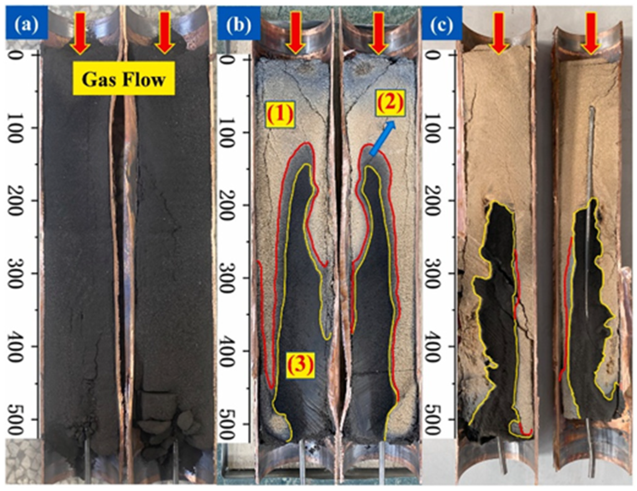
Guo et al. developed the autothermic pyrolysis in situ conversion process (ATS) for oil shale in situ conversion, which is a topochemical reaction method [44,45]. The topological chemical reaction is a chemical heat enhancement process rather than a simple combustion process. It can achieve the in situ cracking of kerogen without continuous external heating. TSA technology releases enough heat energy through the topological chemical reaction between the input limited oxygen and kerogen, so that the kerogen can be cracked to generate oil and gas under low energy input. TSA technology has a faster heating rate and less external energy demand, so it is easier to obtain higher economic effects. Due to the low demand for external energy consumption, TAS technology can also be applied to low-grade oil shale formation. However, the reaction process of TSA technology is complex and difficult to control (Figure 7). In 2016, an ATS in situ conversion pilot project was carried out in the Songliao basin of China to perform technical preparations for commercial ATS technology application [18]. However, the production yield was very unstable and produced 1.68 tons of oil in three months [45].
Li el at. proposed a new thesis in which calcium oxide (CaO) powder is injected into shale formations. The reaction of calcium oxide and water (H2O) releases heat that could heat shale and cause kerogen to crack [46]. Meanwhile, the calcium hydroxide (Ca(OH)2) generated by the reaction of calcium oxide and water has a pore structure that not only improves the permeability of the reservoir, but also fills the gap generated by the pyrolysis of kerogen, which increases the stability of the shale [46]. However, the technology is still at the theoretical stage.

4.4. In Situ Radiant Heating Technology

Raytheon Company proposed radio frequency heating and supercritical fluid extracting technology (RF/CF). The principle of radio frequency heating is that microwaves make the positive and negative poles of material molecules vibrate and change. The intensity of this vibration and polarity change heat the molecules up due to collision and friction [47]. RF/CF technology places the RF transmitter in the shale, heats the shale formation with RF, and then injects supercritical CO2 into the shale formation as a carrier to bring the generated oil and gas to the surface. In addition, Phoenix Wyoming also developed borehole microwave heating technology to heat shale. Many experiments have proven that high-quality oil products can be obtained when using microwaves to heat shale [47,48]. Compared with traditional heating, the microwave heating of organic-rich shale has the advantages of short-time consumption, uniform heating, and selective heating. Radiant heating technology has greatly shortened the heating time and significantly improved the energy utilization efficiency. However, the equipment cost is high, and much electric energy still needs to be consumed to generate RF, which also leads to higher economic costs.
In summary, conductive heating technology is currently the most mature technology in engineering, with the outstanding advantages of a simple principle and low equipment cost. However, the outstanding disadvantage is that this method mainly depends on heat conduction, and the heating rate is slow, which leads to a large amount of heat loss. Convection heating technology uses the convection of high-heat fluid and heat conduction to heat the formation, and can also rotate the heat-injection and production wells, which can greatly shorten the heat conduction distance and improve heating efficiency. Reaction-heat heating technology uses the energy of organic matter in the shale to heat the formation, which greatly reduces the consumption of external energy, so that the technology can be applied to lower-grade oil shale. However, the reaction process of organic-matter combustion is complex and in a dispersed state. How to initiate the reaction at a fixed point and conduct it in a controlled and efficient manner remain to be explored. Radiant heating technology has the characteristics of instantaneous and integral heating, so that the radiant heating of oil shale has high heating speed, low heat loss, and high heating efficiency. However, the disadvantage of radiant heating is that the direct heating range of microwaves is small. Shale beyond this range still needs to rely on inefficient heat conduction. In addition, microwave transmission equipment is precise, expensive, and large. The development of these technologies mainly solves two problems: how to speed up the heating rate and increase the heating efficiency, and how to efficiently transport the generated oil and gas to the ground. Therefore, in the process of developing these technologies, more consideration should be given to these two issues. Although the maturity of the latter three types of heating technology is lower than that of the conductive heating technology, they are worth exploring because they have great potential for improving heating speed and heating efficiency.

5. Factors Affecting the Economic Benefits of In Situ Organic-Rich Shale Conversion

On the basis of the verification of various laboratory simulations and field pilot production, academic and industrial circles have agreed on the technical feasibility of shale-oil exploitation after organic-rich shale in situ conversion. However, the kerogen cracking process is an endothermic reaction that needs to consume a certain amount of energy. In addition, during the heating process, inorganic minerals and water in the shale are heated synchronously and consume a significant amount of heat energy. Meanwhile, due to the long heating time, much of the heat energy of shale is also dissipated into the surrounding rock through heat conduction. In addition to the high heating costs, the required equipment for in situ conversion is more expensive. Therefore, many experts and companies are concerned about the economic feasibility of in situ conversion. The economic feasibility of oil shale in situ conversion depends on whether the energy consumption ratio (value of produced oil and gas products/(heating energy consumption cost + engineering costs)) is higher than 1. Only when the value of the produced petroleum products is significantly greater than the cost of heating energy consumption can it be expected to realize economic benefits through large-scale commercial development, the dilution of engineering, and other costs. Therefore, improving the ratio of the value of oil and gas products to the cost of heating energy consumption is very important. Since the current ICP technology is the most mature, the following mainly regards the economic effects of oil shale in situ conversion with the ICP technology.

5.1. Influence of Heating Mode

Early experiments verified that the cracking reaction process of kerogen is controlled by the reaction temperature and time, and that the time and temperature have complementary effects when the temperature exceeds the critical temperature of the reaction [8,9]. Under geological conditions, the temperature of kerogen cracking to generate oil and gas is generally 50–150 °C [65,66], but this kerogen cracking process generally lasts for thousands or several millions of years, which is evidently too long for industrial production. In order to ensure that the hydrocarbon generation reaction of kerogen can occur in large quantities in a short period of time, a higher reaction temperature is generally maintained in in situ conversion engineering to reduce the reaction time. Therefore, when a large amount of hydrocarbon is generated from kerogen, it cannot be determined solely via temperature, and the kinetic parameters and heating rate need to be considered. Many semiopen, open, and closed kerogen cracking simulation experiments have proven that higher temperatures can greatly shorten the reaction time of kerogen cracking [7,16,67,68,69]. However, too high of a reaction temperature not only unnecessarily increases energy consumption, but also leads to the cracking of large amounts of liquid hydrocarbons into gases, which reduces the economic benefits. Therefore, an appropriate heating temperature or heating mode can be determined to obtain the highest hydrocarbon (HC) yield with the minimal energy consumption.
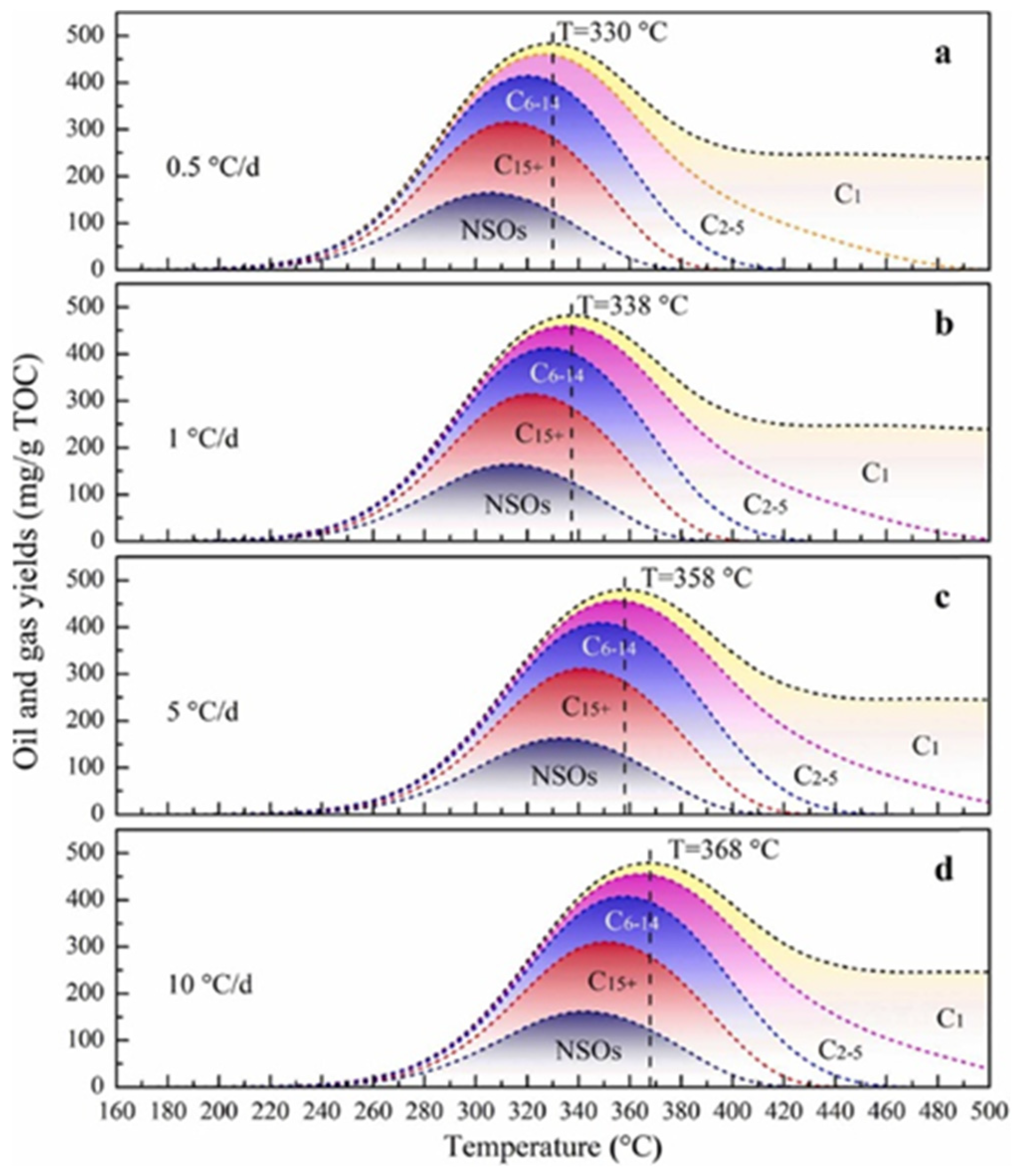
By obtaining the kinetic parameters of hydrocarbon generation, Hou et al. [7] simulated the in situ conversion process of organic-rich shale at heating rates of 0.5, 1, 5, and 10 °C/d, and found that the temperatures at which Chang7 kerogen produced the maximal HC yield were 330, 338, 358, and 368 °C, respectively (Figure 8). Meanwhile, when the temperature exceeds the temperature at maximal HC yield, the HC yield generally exhibits a downward trend, but the gas/oil ratio (GOR) increasingly grows. Song et al. studied the organic-matter evolution of lacustrine shale in the Qingshankou Formation of the Songliao Basin and the Chang 7 Member of the Ordos Basin using a semiclosed heating system under a constant temperature [70]. Considering the quality and quantity of the produced oil, the conversion degree of kerogen, and the efficiency of hydrocarbon expulsion, the optimal temperature ranges of the Chang7 shale and Qingshankou shale are 400–450 and 350–425 °C during oil shale in situ conversion, respectively [70]. This indicates that the pyrolytic processes of different shales are distinct. Alhesan et al. conducted isothermal pyrolysis experiments with El Lajjun shale at different temperatures and times in a closed system, and good oil production could be achieved at 280 °C for 14 days [67]. However, when the temperature was lower than 300 °C, the sulfur content of the obtained product was high (12 wt % of oil), but it could be significantly reduced to approximately 7 wt % when the temperature was 300–320 °C [67]. Ma et al. used experiments to simulate the effects of different heating temperatures, heating rates, and constant temperature times on the quality and quantity of the produced oil. With an increasing heating rate, the total oil and gas yield gradually decreased, and the relative content of the saturated hydrocarbon component decreased [71]. This may have been because kerogen in organic-rich shale does not have enough time to participate in the reaction under a high heating rate. At a constant temperature of 350 °C with increasing constant temperature time, the fuller the pyrolysis of oil shale organic matter is, the higher the oil and gas yield is, and the saturated hydrocarbon component of the produced oil increases slightly [69]. Moreover, experiments showed that, with increasing constant temperature time, small pores gradually develop into relatively large pores, and the permeability of the shale increases [72].
Therefore, during in situ shale conversion, it is necessary to fully consider the conditions of the target formation and set up a reasonable heating mode to improve the energy consumption ratio. For instance, at the low-temperature stage, the temperature can be rapidly raised to make the kerogen reach the cracking temperature fast, avoiding excessive heat conduction and heat dissipation; at the medium-temperature stage, the temperature should be raised slowly to ensure that the kerogen and NSO compounds can be fully cracked and reduce the content of C6–14 cracking, which can increase the quality and yield of the shale oil. Meanwhile, this heating mode can, to some extent, alleviate the phenomenon of an uneven pyrolysis reaction process caused by the uneven heating of the target layer.

5.2. Influence of Formation Conditions

Previous simulation experiments found that Types I and IIa (a subtype of Type II) kerogen are more inclined to generate oil, Types IIb (a subtypes of Type II) and III kerogen are more inclined to generate gas, and the main oil generation period of different kerogen types is 0.7–1.35 Easy%Ro [12,73]. When the maturity of the kerogen is greater than 1.35 Easy%Ro, its oil generation potential is basically exhausted. Moreover, there are discrepancies in the kinetic parameters between different kerogen types, so the evolutionary process during in situ conversion is also different [7,73]. The activation energy of Types Ⅱ and Ⅲ kerogens covers a wide distribution range, while Type Ⅰ a narrow one, and the average activation energy of kerogens follows the order of Type Ⅲ > Type Ⅱ > Type Ⅰ. This shows that the potential of kerogen cracking to generate oil and gas is controlled by the maturity and kerogen type. A hydrocarbon generation simulation experiment found that the presence of some minerals could catalyze the kerogen cracking reaction. For example, carbonate (dolomite) promotes oil generation to a certain extent, but inhibits gas generation, while for silicate (feldspar, quartz, and clay), this is the opposite [21,74]. Pyrite is generally beneficial to oil and gas generation [21], and some findings suggest that the rate of petroleum formation depends critically on the concentration of sulfur radicals generated during the initial stages of thermal maturation [75]. Moreover, mineralogical composition determines the brittleness index of the shale. The higher the brittleness index of the shale is, the easier fracturing is, which is conducive to the formation of fractures.
The influence of the water content in shale on the energy consumption ratio of in situ conversion mainly has two aspects. On the one hand, water consumes large amounts of heat energy during heating and vaporization due to its large specific heat capacity [20]. On the other hand, in the presence of water, kerogen in shale can not only undergo thermal cracking reactions, but also chemical reactions with high-temperature water in the gas or liquid phase due to the high temperature [39,76]. In hydrothermal cracking reactions, high-temperature water may participate in the reaction as a catalyst, reactant, and/or solvent. In addition, water can provide H+ and OH as reactants that can improve the oil and gas yield of organic-rich shale in situ conversion [39,71,76].
As mentioned above, when the energy consumption of heating shale is less than the energy of producing oil, project and other costs need to be diluted by the scale of exploitation, which renders it necessary to consider its scale when selecting the target formation. Therefore, shale for the commercial development of underground in situ conversion should meet the following conditions: (1) the TOC value of the shale must be more than 6%, mainly consisting of Types I and IIa organic matter; (2) the Ro value must be 0.5%–1.0%; (3) the thickness must be more than 15 m; (4) the burial depth must be less than 3000 m, and the area more than 50 km2; (5) the roof and floor of the shale section must be well-sealed; (6) the formation water content must be less than 5% [1,2,6].

5.3. Distribution Pattern of Wells

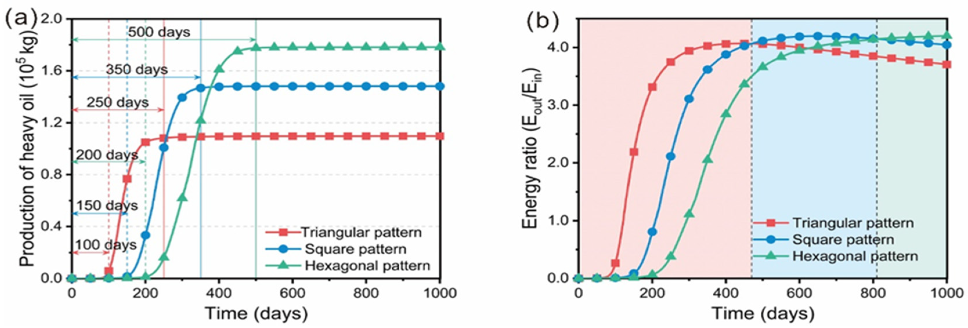
Fan et al. observed that heating well spacing significantly impacts shale formation temperature through analog computation [11,68]. The larger the spacing of the heating wells is, the earlier and sharper the peak of the oil and gas yield is. This may be because the larger heater spacing allows for the reservoir to heat more evenly, which shortens the time interval of kerogen decomposition [11,68]. However, exorbitantly heating the well spacing lengthens the heating time too much to perform industrial production, and renders the kerogen conversion rate relatively low. Huang et al. [11] considered that, with the same well spacing, if the production period is shorter than 400 days, and a higher heating rate is needed, a more intensive heating well pattern, such as a triangular well pattern, should be selected. If the energy consumption ratio is given priority, and the heating period is longer than 800 days, then the hexagonal well pattern is better (Figure 9). In the process of in situ shale conversion, the energy consumption ratio of horizontal well heating is significantly higher than that of vertical well heating because horizontal well heating can significantly reduce the consumption of heat energy in the surrounding rock. Lu et al. calculated with a simulation that, when the well spacing of horizontal wells is half the thickness of the shale formation, the energy consumption ratio is the highest, and smaller and larger well spacing leads to a reduction in the energy consumption ratio [77]. When the well spacing is significantly greater than the thickness of the shale half layer, the surrounding rock also reaches a higher temperature during the heating process, which causes a considerable amount of heat energy to be transferred into the surrounding rock. However, under the condition of small well spacing, when the temperature near the production well reaches the effective cracking temperature, the temperature at the edge of the shale is still low, and the organic matter in the shale does not start to effectively crack, which reduces the oil and gas yield. Therefore, the well spacing should be determined on the basis of the thickness of the target formation. Meanwhile, small well spacing and horizontal wells mean increasing drilling costs and reducing the final benefits after considering the engineering operation costs. Ground conditions are also an important reference indicator for the distribution pattern of wells, and horizontal wells can be considered for areas that are not suitable for construction. In summary, the combination of horizontal well and multiwell methods can slightly reduce the heating cost and significantly reduce the time cost, but this increases the drilling cost. Therefore, it is necessary to comprehensively consider the heating and time costs, ground conditions, and engineering cost in the future, and conduct overall quantitative optimization to determine the distribution pattern of the wells.

5.4. Catalytic Agent

The simulation calculation results of the kinetic hydrocarbon generation experiment show that, under other conditions being unchanged, with the reduction in activation energy of the kerogen cracking reaction, lower temperature or shorter heating time was required for the effective pyrolysis of kerogen [8,9]. In the process of in situ shale conversion, this principle is the same. In industrial production, adding a catalyst is an effective technology to reduce the reaction activation energy. Moreover, the catalyst can accelerate the breaking of long-chain molecules, and convert solid or heavy organic matter into light hydrocarbons, which improves the fluidity and quality of oil [78,79,80,81,82]. Therefore, adding a catalyst is one of the efficiency enhancement methods of in situ shale conversion.
Song et al. used natural clay, attapulgite, and 3-mercaptopropyltrimethoxysilane (MPTMS) to optimize the preparation of catalyst SO3H–APG, which can reduce the pyrolytic temperature and activation energy of shale, improve the hydrocarbon yield, and reduce the content of oxygen- and nitrogen-containing compounds [78]. Chang et al. used transition metal salts to catalyze the pyrolysis of shale. The results showed that both CoCl2 and NiCl2 could promote the pyrolysis of organic-rich shale and the secondary pyrolysis of generated oil [82]. Yu et al. proposed a clin/SBA-15 catalyst prepared with clinoplite and conducted indepth research on the catalytic behavior of oil shale in situ conversion. The results showed that the saturated hydrocarbon content of the oil produced by the clin/SBA-15 catalyst increased, the H/C ratio increased, and the O/C ratio decreased [83]. In addition, Clin/SBA-15 did not exhibit activity attenuation in the seven-day shale pyrolysis test [83]. Sun et al. found that the addition of CrCl3 reduced the temperature of shale pyrolysis and the activation energy. In addition, the CrCl3 catalyst reduced the content of oxygen-contained compounds, and increased the content of hydrocarbons and short-chain aliphatic hydrocarbons in shale oil [84]. Furthermore, many catalysts, such as liquid acid, organometallic complexes, NiMo, CoMo, CoCl2 6H2O, dodecane, diatomite, and zeolite molecular sieves, have been proven in the laboratory to change the quality or yield of generated oil [78,79,80,81,82]. As mentioned above, water can provide H+ and OH- as reactants in the cracking reaction. Therefore, high-temperature water can be used as a catalyst to improve the hydrocarbon yield and prevent coking during the process of in situ conversion [39,56].
Generally, the catalyst should come into contact with the reactants, which requires the catalyst to be widely distributed in shale formations. For some solid catalysts, it is difficult to achieve this goal with existing engineering techniques. Evidently, conductive heating technology and radiant heating technology hinder achieving this goal, but convection heating technology can carry the catalyst through the fluid when the catalyst is easily carried by the fluid. Therefore, when studying catalysts for kerogen hydrocarbon generation reactions, it is necessary to consider the applicability of the catalysts. In addition, an experimental study found that the temperature required for shale pyrolysis decreased when the shale was heated by microwaves, which indicates that microwave heating may accelerate the kerogen cracking reaction [47,48].

6. Influence of oil Shale In Situ Conversion on a Groundwater Environment

The temperature of shale formation is generally greater than 300 °C during in situ conversion, which may last for several years. During the heating process, the pyrolysis of oil shale generates oil and natural gas, and produces sulfide, nitride, and benzene, toluene, ethylbenzene, xylene (BTEX), a comprehensive indicator of the total organic matter in water that directly reflects the degree of water pollution by organic matter and other pollutants [20,56,64,85,86]. Hu et al. found that high-temperature water–rock interactions release more organic compounds, such as phenol, BTEX, and petroleum components, and aggravate the organic pollution of groundwater. Among them, TOCwater content (a comprehensive indicator of total organic matter in water) in the simulated aquifer water sample after pyrolysis was 38.8 mg/L, approximately 30 times the initial concentration, which is much higher than the general drinking-water quality standard (5 mg/L, China) [56]. Some of these pollutants flow out of the production well together with oil and gas, and the other part remains in the shale formation. Oil, natural gas, and a series of pollutants retained in shale formations are released into the groundwater environment under the action of infiltration and pollute the groundwater [64]. In addition, as described in Section 3, porosity and permeability grows much larger during in situ conversion, which changes the shale formation from dense and impermeable to high-permeability. On the one hand, oil, natural gas, and a series of pollutants retained in the formation are released into the upper and lower aquifers. On the other hand, water can enter and exit the pyrolysis zone through fractures. Therefore, groundwater pollution is inevitable. This may cause lasting damage to the ecological environment of groundwater, and pollute drinking water in the surrounding areas.
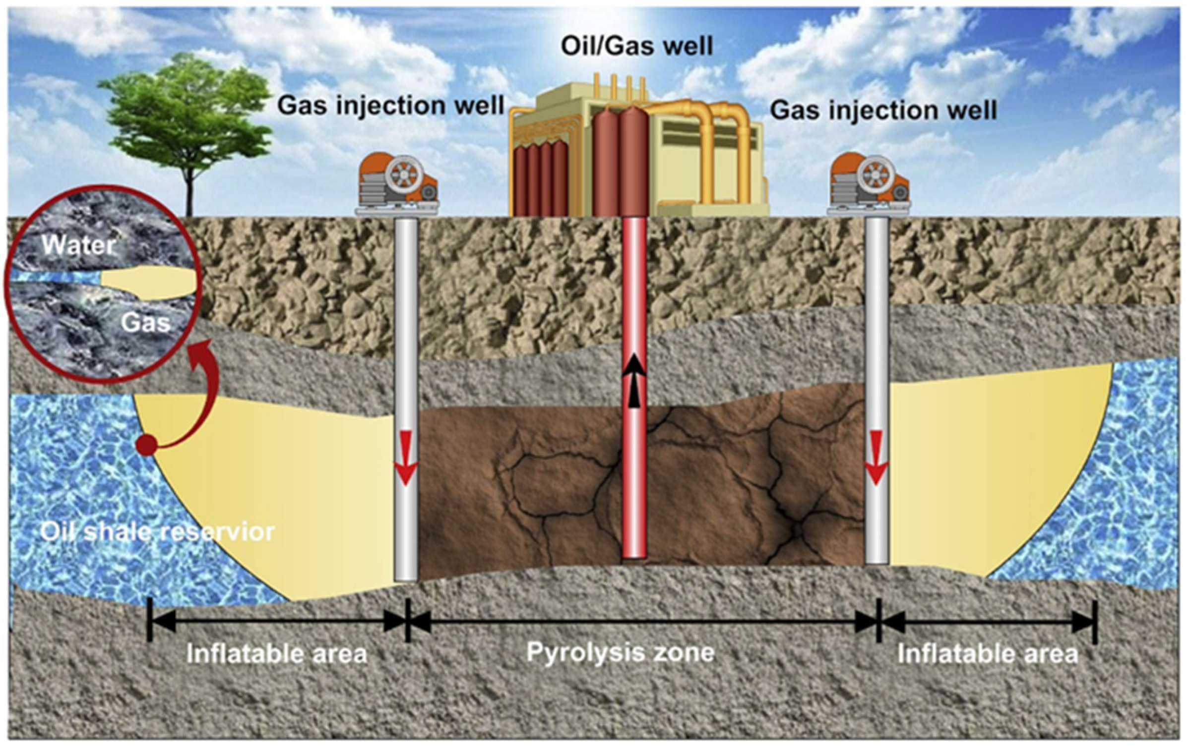
Therefore, to solve the groundwater pollution issue in the process of oil shale in situ conversion, some sealing technologies that block the passage between the pyrolysis zone and surrounding groundwater were proposed, such as the freeze-wall, grouting-curtain, and marginal gas-injection technologies [34,87,88,89,90]. Shell developed the freezing-wall technology, which uses the freeze wall formed by circulating a refrigerant to prevent groundwater from entering the high-temperature cracking zone [87]. Before heating the shale formation, the formation water in the reaction zone needs to be pumped out. After shale-oil exploitation, clean water is used to wash pollutants in the high-temperature reaction zone. However, it takes a long time to form a freeze wall, and the cost is high [87]. The grouting-curtain technology refers to pressing the cement slurry into the pores and fractures of the formation, enabling it to block the flow path of the fluid in the formation after solidification [88]. Although grouping technology can achieve a good water-stopping effect, its project cost is still high [90]. Marginal gas-injection technology injects a certain amount of gas pressure into the edge of the oil shale in situ conversion zone through a borehole to form a high-pressure gas filling zone (Figure 10) that is used to block the groundwater outside the shale formation from entering the oil shale in situ conversion zone [89]. Due to the gas characteristics of low viscosity and strong fluidity, this technology can obtain a large closed range, but it is necessary to reasonably control the gas injection flow and pressure to achieve the water-stopping effect of the gas drive without affecting the in situ heating and cracking process [89].
In summary, oil shale in situ conversion and exploitation seriously impact the ecological environment of groundwater. It is necessary to develop an environmentally friendly, low-cost, and effective method for preventing groundwater pollution.

7. Prospects

7.1. Description of the Hydrocarbon Generation Process of Target Formation

The hydrocarbon generation process of organic-rich shales during in situ conversion can be inverted by the kinetic parameters. This allows for us to predict the oil generation period, oil yield, and relevant parameters of oil shale in situ conversion. Whether the obtained kinetic parameters can be successfully extrapolated to geological conditions mainly depends on the approximation of thermal simulation testing and geological conditions. Therefore, it is necessary to design a thermal simulation experiment according to the technical conditions of oil shale in situ conversion to obtain the kinetic hydrocarbon generation parameters of the target shale. On the basis of accurately depicting the hydrocarbon generation process of organic-rich target shales under the condition of in situ conversion, the temperature and time of in situ conversion can be adjusted in real time. Meanwhile, due to the uneven distribution of heat energy in the target layer during heating, the basin modeling technology can be used to analyze the hydrocarbon generation process of the entire target formation by integrating the dynamic parameters and formation temperature distribution.

7.2. Developed New and Efficient Catalyst

In fact, the catalyst can reduce the activation energy of kerogen cracking and accelerate the cracking of long-chain molecules, thereby reducing costs and increasing shale oil production, which is one of the important research fields of oil shale in situ conversion. As described in Section 5.4, some catalysts were proven in the laboratory to effectively reduce the activation energy of kerogen cracking, but further research is needed. Meanwhile, the catalyst should come into contact with the reactant, which makes the catalyst need to be widely distributed in shale formations. It is difficult for some solid catalysts to achieve this goal under existing technical conditions. Some scholars have applied nanotechnology to transform catalysts into nanoparticles, which allows for them to be distributed in the target layer through a fluid [91]. Therefore, the application of nanoparticle catalysts in oil shale in situ conversion can be further strengthened. Liquid catalysts or catalysts that are easily soluble in solvents are also a research direction.

7.3. Supporting Carbon Storage Technology

As described in Section 2, organic-rich shale in situ conversion further develops the pores and fractures of the shale formation, and the overall solid skeleton can shrink into 45% of the rock. Therefore, organic-rich shale formation after in situ conversion is good for carbon storage. Carbon neutrality is globally imperative; therefore, carbon dioxide can be stored in depleted organic-rich shale formations after in situ conversion, which is greatly significant for carbon capture and storage (CCS), and further improves the engineering efficiency of in situ conversion. Therefore, the pore structure of the target layer, the sealing of the cover layer, and the CO2 adsorption capacity of the target layer after in situ conversion are important future research directions.

Author Contributions

Conceptualization, H.G. and P.C.; methodology, S.L. and H.G.; investigation, S.L.; resources, H.G. and P.C.; data curation, S.L.; writing—original draft preparation, S.L.; writing—review and editing, H.G. and P.C.; visualization, S.L.; supervision, H.G.; project administration, P.C.; funding acquisition, H.G. and P.C. All authors have read and agreed to the published version of the manuscript.

Funding

This study was supported by the National Natural Science Foundation of China (grants no. 42173031 and 42272162). This is contribution No. IS-3354 from GIGCAS.

Data Availability Statement

Not applicable.

Conflicts of Interest

The authors declare no conflict of interest.

References

  1. Zhao, W.; Hu, S.; Hou, L. Connotation and strategic role of in-situ conversion processing of shale oil underground in the onshore China. Pet. Explor. Dev. 2018, 45, 563–572. [Google Scholar] [CrossRef]
  2. Hu, S.; Zhao, W.; Hou, L.; Yang, Z.; Zhu, R.; Wu, S.; Bai, B.; Jin, X. Development potential and technical strategy of continental shale oil in China. Pet. Explor. Dev. 2020, 47, 877–887. [Google Scholar] [CrossRef]
  3. Zou, C.; Zhu, R.; Dong, D.; Wu, S. Scientific and technological progress, development strategy and policy suggestion regarding shale oil and gas. Acta Pet. Sin. 2020, 43, 1675–1686. [Google Scholar]
  4. Zou, C.N.; Zhai, G.M.; Zhang, G.Y.; Wang, H.J.; Zhang, G.S.; Li, J.Z.; Wang, Z.M.; Wen, Z.X.; Ma, F.; Liang, Y.B.; et al. Formation, distribution, potential and prediction of global conventional and unconventional hydrocarbon resources. Pet. Explor. Dev. 2015, 42, 14–28. [Google Scholar] [CrossRef]
  5. Jin, Z.J.; Zhu, R.K.; Liang, X.P.; Shen, Y.Q. Several issues worthy of attention in current lacustrine shale oil exploration and development. Pet. Explor. Dev. 2021, 48, 1471–1484. [Google Scholar] [CrossRef]
  6. Li, J.; Tang, D.; Xue, H.; Zheng, D.; Du, D. Discission of Oil Shale In-situ Conversion Process in China. J. Southwest Pet. Univ. 2014, 36, 58–64. [Google Scholar]
  7. Hou, L.; He, K.; Zhai, J.; Mi, J.; Weng, N. Compositional kinetics for hydrocarbon evolution in the pyrolysis of the Chang 7 organic matter: Implications for in-situ conversion of oil shale. J. Anal. Appl. Pyrolysis 2022, 162, 105434. [Google Scholar] [CrossRef]
  8. Waples, D.W. The kinetics of in-reservoir oil destruction and gas formation: Constraints from experimental and empirical data, and from thermodynamics. Org. Geochem. 2000, 31, 553–575. [Google Scholar] [CrossRef]
  9. Waples, D.W. Time and Temperature in Petroleum Formation—Application of Lopatins Method to Petroleum-Exploration. AAPG Bull. 1980, 64, 916–926. [Google Scholar]
  10. Gai, H.; Tian, H.; Cheng, P.; Zhou, Q.; Li, T.; Wang, X.; Xiao, X. Influence of retained bitumen in oil-prone shales on the chemical and carbon isotopic compositions of natural gases: Implications from pyrolysis experiments. Mar. Pet. Geol. 2019, 101, 148–161. [Google Scholar] [CrossRef]
  11. Huang, H.; Yu, H.; Xu, W.; Lyu, C.; Micheal, M.; Xu, H.; Liu, H.; Wu, H. A coupled thermo-hydro-mechanical-chemical model for production performance of oil shale reservoirs during in-situ conversion process. Energy 2023, 268, 126700. [Google Scholar] [CrossRef]
  12. Behar, F.; Lorant, F.; Lewan, M. Role of NSO compounds during primary cracking of a Type II kerogen and a Type III lignite. Org. Geochem. 2008, 39, 1–22. [Google Scholar] [CrossRef]
  13. Lee, K.J.; Finsterle, S.; Moridis, G.J. Analyzing the impact of reaction models on the production of hydrocarbons from thermally upgraded oil shales. J. Pet. Sci. Eng. 2018, 168, 448–464. [Google Scholar] [CrossRef]
  14. Pei, S.; Wang, Y.; Zhang, L.; Huang, L.; Cui, G.; Zhang, P.; Ren, S. An innovative nitrogen injection assisted in-situ conversion process for oil shale recovery: Mechanism and reservoir simulation study. J. Pet. Sci. Eng. 2018, 171, 507–515. [Google Scholar] [CrossRef]
  15. Li, S.Y.; Yue, C.T. Study of pyrolysis kinetics of oil shale. Fuel 2003, 82, 337–342. [Google Scholar] [CrossRef]
  16. Zhang, B.; Yu, C.; Cui, J.; Mi, J.; Li, H.; He, F. Kinetic simulation of hydrocarbon generation and its application to in-situ conversion of shale oil. Pet. Explor. Dev. 2019, 46, 1288–1296. [Google Scholar] [CrossRef]
  17. Niu, D.; Sun, P.; Ma, L.; Zhao, K.A.; Ding, C. Porosity evolution of Minhe oil shale under an open rapid heating system and the carbon storage potentials. Renew. Energy 2023, 205, 783–799. [Google Scholar] [CrossRef]
  18. Bai, F.; Sun, Y.; Liu, Y.; Guo, M. Evaluation of the porous structure of Huadian oil shale during pyrolysis using multiple approaches. Fuel 2017, 187, 1–8. [Google Scholar] [CrossRef]
  19. Thomas, M.; Jack, E.; Tom, F. In-Situ Oil Shale Development in Jordan through ICP Technology. In Proceedings of the International Petroleum Exhibition and Conference, Abu Dhabi, United Arab Emirates, 10–14 November 2014; Society of Petroleum Engineers: Abu Dhabi, United Arab Emirates, 2014. [Google Scholar]
  20. Kang, Z.; Zhao, Y.; Yang, D. Review of oil shale in-situ conversion technology. Appl. Energy 2020, 269, 115121. [Google Scholar] [CrossRef]
  21. Zhao, Q.; Dong, Y.; Zheng, L.; Xie, T.; Bawaa, B.; Jin, H.; Guo, L. Sub- and supercritical water conversion of organic-rich shale with low-maturity for oil and gas generation: Using Chang 7 shale as an example. Sustain. Energy Fuels 2022, 7, 155–163. [Google Scholar] [CrossRef]
  22. Zhang, P.; Xu, Y.; Meng, Q.; Liu, Z.; Zhang, J.; Shen, L.; Zhang, S. Sequence Stratigraphy and Geochemistry of Oil Shale Deposits in the Upper Cretaceous Qingshankou Formation of the Songliao Basin, NE China: Implications for the Geological Optimization of In Situ Oil Shale Conversion Processing. Energies 2020, 13, 2964. [Google Scholar] [CrossRef]
  23. Wang, G.Y.; Liu, S.W.; Yang, D.; Fu, M.X. Numerical study on the in-situ pyrolysis process of steeply dipping oil shale deposits by injecting superheated water steam: A case study on Jimsar oil shale in Xinjiang, China. Energy 2022, 239, 122182. [Google Scholar] [CrossRef]
  24. Liu, B.; Liu, Y.; Liu, Y.; He, J.; Gao, Y.; Wang, H.; Fan, J.; Fu, X. Prediction of low-maturity shale oil produced by in situ conversion: A case study of the first and second members of Nenjiang Formation in the Central Depression, southern Songliao Basin, Northeast China. Pet. Geol. Exp. 2020, 42, 533–544. [Google Scholar]
  25. Li, J.H.; Shan, X.L.; Song, X.; He, W.T. Evaluation of the organic matter product of Huadian oil shale during pyrolysis using multiple approaches: Guidance for the in situ conversion of oil shale. J. Anal. Appl. Pyrolysis 2022, 167, 105656. [Google Scholar] [CrossRef]
  26. Hou, L.; Ma, W.; Luo, X.; Liu, J. Characteristics and quantitative models for hydrocarbon generation-retention-production of shale under ICP conditions: Example from the Chang 7 member in the Ordos Basin. Fuel 2020, 279, 118497. [Google Scholar] [CrossRef]
  27. He, W.; Meng, Q.A.; Lin, T.; Wang, R.; Liu, X.; Ma, S.; Li, X.; Yang, F.; Sun, G. Evolution of in-situ permeability of low-maturity shale with the increasing temperature, Cretaceous Nenjiang Formation, northern Songliao Basin, NE China. Pet. Explor. Dev. 2022, 49, 453–464. [Google Scholar] [CrossRef]
  28. Le Doan, T.V.; Bostrom, N.W.; Burnham, A.K.; Kleinberg, R.L.; Pomerantz, A.E.; Allix, P. Green River Oil Shale Pyrolysis: Semi-Open Conditions. Energy Fuels 2013, 27, 6447–6459. [Google Scholar] [CrossRef]
  29. Tanaka, P.; Yeakel, J.; Symington, W. Plan to Test ExxonMobil’s In Situ Oil Shale Technology on a Proposed RD & D Lease. In Proceedings of the 31st Oil Shale Symposium, Golden, CO, USA, 7–21 October 2011. [Google Scholar]
  30. Sullivan, N.; Anyenya, G.; Haun, B.; Daubenspeck, M.; Bonadies, J.; Kerr, R.; Fischer, B.; Wright, A.; Jones, G.; Li, R.; et al. In-ground operation of Geothermic Fuel Cells for unconventional oil and gas recovery. J. Power Sources 2016, 302, 402–409. [Google Scholar] [CrossRef]
  31. Anyenya, G.A.; Braun, R.J.; Lee, K.J.; Sullivan, N.P.; Newman, A.M. Design and dispatch optimization of a solid-oxide fuel cell assembly for unconventional oil and gas production. Optim. Eng. 2018, 19, 1037–1081. [Google Scholar] [CrossRef]
  32. Sun, Y.; Rapakin, F.; Han, W.; Maljim, Y.S.; Li, Q.; Bukharkin, A.; Yang, Y.; Yuan, Z.; Liu, B.; Guo, W.; et al. A Method of Underground In-Situ Heating of Oil Shale. CN103174406B, 12 February 2015. [Google Scholar]
  33. Yang, Y. Theoretical and Experimental Study on In-Situ Pyrolysis of Oil Shale by High Pressure-Power Frequency Electric Heating. Ph.D. Thesis, Jilin University, China, 2014. [Google Scholar]
  34. Sun, Y.; Guo, W.; Deng, S. The status and development trend of in-situ conversion and drilling exploitation technology for oil shale. Drill. Eng. 2021, 48, 57–67. [Google Scholar]
  35. Li, N.; Wang, Y.; Chen, F.; Han, Y.; Chen, W.; Kon, K. Development Status and Prospects of In-situ Conversion Technology in Oil Shale. Spec. Oil Gas Reserv. 2022, 29, 1–8. [Google Scholar]
  36. Kang, Z.; Zhao, Y.; Yang, D.; Zhao, J.; Wang, L. Pilot test of in-situ steam injection for oil and gas production from oil shale and applicability of and multi-mode in-situ thermal recovery technology. Acta Pet. Sin. 2021, 42, 1458–1468. [Google Scholar]
  37. Kang, Z.Q.; Zhao, Y.S.; Yang, D.; Tian, L.J.; Li, X. A pilot investigation of pyrolysis from oil and gas extraction from oil shale by in-situ superheated steam injection. J. Pet. Sci. Eng. 2020, 186, 106785. [Google Scholar] [CrossRef]
  38. Kang, Z.Q.; Xie, H.Y.; Zhao, Y.S.; Zhao, J. The feasibility of in-situ steam injection technology for oil shale underground retorting. Oil Shale 2020, 37, 119–138. [Google Scholar] [CrossRef]
  39. Zhao, F.; Li, B.; Che, D.; Liu, S. The mechanism of H2O in the superheated steam affecting the quality of in-situ pyrolysates of oil shale kerogen: Part B-favorable conversion of residues. Fuel 2023, 337, 127146. [Google Scholar] [CrossRef]
  40. Huang, H.; Chen, S.J.; Lu, J.G.; Ma, J.; He, J.B. The influence of water on the thermal simulation experiment of hydrocarbon generation and expulsion. Pet. Sci. Technol. 2017, 35, 783–788. [Google Scholar] [CrossRef]
  41. Ma, Z.; Zheng, L.; Zhao, Z.; Xu, Q.; Zheng, J. Laboratory Experiment of In-situ Conversion Process in Near-critical Water of Huadian Oil Shale of Jilin. Sci. Technol. Eng. 2016, 16, 55–60. [Google Scholar]
  42. Kar, T.; Hascakir, B. In-situ kerogen extraction via combustion and pyrolysis. J. Pet. Sci. Eng. 2017, 154, 502–512. [Google Scholar] [CrossRef]
  43. Bauman, J.H.; Deo, M. Simulation of a Conceptualized Combined Pyrolysis, In Situ Combustion, and CO2 Storage Strategy for Fuel Production from Green River Oil Shale. Energy Fuels 2012, 26, 1731–1739. [Google Scholar] [CrossRef]
  44. Guo, W.; Yang, Q.; Deng, S.; Li, Q.; Sun, Y.; Su, J.; Zhu, C. Experimental study of the autothermic pyrolysis in-situ conversion process (ATS) for oil shale recovery. Energy 2022, 258, 124878. [Google Scholar] [CrossRef]
  45. Guo, W.; Li, Q.; Deng, S.-H.; Wang, Y.; Zhu, C.-F. Mechanism and reservoir simulation study of the autothermic pyrolysis in-situ conversion process for oil shale recovery. Pet. Sci. 2023, 20, 1053–1067. [Google Scholar] [CrossRef]
  46. Li, S.; Li, X.; Wang, S.; Ma, S.; Sun, Y. Theory and method of in-situ conversion of shale oil by chemical thermal. J. Eng. Geol. 2022, 30, 127–143. [Google Scholar]
  47. Taheri-Shakib, J.; Kantzas, A. A comprehensive review of microwave application on the oil shale: Prospects for shale oil production. Fuel 2021, 305, 121519. [Google Scholar] [CrossRef]
  48. Wang, M.; Zhang, Y.; Li, J.; Ma, R.; Wang, X.; Li, Y.; Shao, H.; Zhang, J.; Fei, J.; Deng, Z.; et al. Thermal and nonthermal effect of microwave irradiation on the pore microstructure and hydrocarbon generation of organic matter in shale. Mar. Pet. Geol. 2023, 150, 106151. [Google Scholar] [CrossRef]
  49. He, W.; Sun, Y.; Guo, W.; Shan, X. Controlling the in-situ conversion process of oil shale via geochemical methods: A case study on the Fuyu oil shale, China. Fuel Process. Technol. 2021, 219, 106876. [Google Scholar] [CrossRef]
  50. He, W.; Sun, Y.; Shan, X. Organic matter evolution in pyrolysis experiments of oil shale under high pressure: Guidance for in situ conversion of oil shale in the Songliao Basin. J. Anal. Appl. Pyrolysis 2021, 155, 105091. [Google Scholar] [CrossRef]
  51. Eseme, E.; Littke, R.; Krooss, B.M. Factors controlling the thermo-mechanical deformation of oil shales: Implications for compaction of mudstones and exploitation. Mar. Pet. Geol. 2006, 23, 715–734. [Google Scholar] [CrossRef]
  52. Zhao, K.A.; Sun, P.; Yu, F.; Liu, R.; Zhang, D. Study on Reservoir Physical Properties of Oil Shale During Heating in Minhe Basin. Xinjiang Pet. Geol. 2020, 41, 158–163. [Google Scholar]
  53. Xu, J.; Chen, Z.; Zhou, D.; Nie, W.; Li, R. Review on the Characteristics of Pyrolysis During In-situ Conversion of Oil Shale. J. Southwest Pet. Univ. 2021, 43, 220–226. [Google Scholar]
  54. Sun, J.; Xiao, X.; Cheng, P.; Wang, M.; Tian, H. The relationship between oil generation, expulsion and retention of lacustrine shales: Based on pyrolysis simulation experiments. J. Pet. Sci. Eng. 2021, 196, 107625. [Google Scholar] [CrossRef]
  55. Xu, S.; Lü, X.; Sun, Y.; Guo, W.; Li, Q.; Liu, L.; Kang, S.; Deng, S. Optimization of temperature parameters for the autothermic pyrolysis in-situ conversion process of oil shale. Energy 2023, 264, 126309. [Google Scholar] [CrossRef]
  56. Hu, S.; Xiao, C.; Liang, X.; Cao, Y.; Wang, X.; Li, M. The influence of oil shale in situ mining on groundwater environment: A water-rock interaction study. Chemosphere 2019, 228, 384–389. [Google Scholar] [CrossRef] [PubMed]
  57. Zeng, H.; He, W.; Yang, L.; Su, J.; Meng, X.; Cen, X.; Guo, W. Evolution of Biomarker Maturity Parameters and Feedback to the Pyrolysis Process for In Situ Conversion of Nongan Oil Shale in Songliao Basin. Energies 2022, 15, 3715. [Google Scholar] [CrossRef]
  58. Wang, G.; Yang, D.; Kang, Z.; Zhao, J. Anisotropy in Thermal Recovery of Oil Shale Part 1: Thermal Conductivity, Wave Velocity and Crack Propagation. Energies 2018, 11, 77. [Google Scholar] [CrossRef]
  59. Geng, Y.; Liang, W.; Liu, J.; Cao, M.; Kang, Z. Evolution of Pore and Fracture Structure of Oil Shale under High Temperature and High Pressure. Energy Fuels 2017, 31, 10404–10413. [Google Scholar] [CrossRef]
  60. Xu, H.; Yu, H.; Fan, J.; Xia, J.; Liu, H.; Wu, H. Formation mechanism and structural characteristic of pore-networks in shale kerogen during in-situ conversion process. Energy 2022, 242, 122992. [Google Scholar] [CrossRef]
  61. Kang, Z.; Yang, D.; Zhao, Y.; Hu, Y. Thermal cracking and corresponding permeability of Fushun oil shale. Oil Shale 2011, 28, 273–283. [Google Scholar] [CrossRef]
  62. Kibodeaux, K.R. Evolution of Porosity, Permeability, and Fluid Saturations during Thermal Conversion of Oil Shale. In Proceedings of the SPE Annual Technical Conference and Exhibition, Amsterdam, The Netherlands, 27–29 October 2014. [Google Scholar]
  63. Meng, X.; Bian, J.; Li, J.; Ma, Z.; Long, Q.; Su, J. Porous aluminosilicates catalysts for low and medium matured shale oil in situ upgrading. Energy Sci. Eng. 2020, 8, 2859–2867. [Google Scholar] [CrossRef]
  64. Brandt, A.R. Converting oil shale to liquid fuels: Energy inputs and greenhouse gas emissions of the Shell in situ conversion process. Environ. Sci. Technol. 2008, 42, 7489–7495. [Google Scholar] [CrossRef]
  65. Tissot, B.; Durand, B.; Espitali, J.; Combaz, A. Influence of Nature and Diagenesis of Organic-Matter in Formation of Petroleum. AAPG Bull. 1974, 58, 499–506. [Google Scholar]
  66. Hou, D.; Feng, Z. Oil and Gas Geochemistry; Petroleum Industry Press: Beijing, China, 2011. [Google Scholar]
  67. Alhesan JS, A.; Fei, Y.; Marshall, M.; Jackson, W.R.; Qi, Y.; Chaffee, A.L.; Cassidy, P.J. Long time, low temperature pyrolysis of El-Lajjun oil shale. J. Anal. Appl. Pyrolysis 2018, 130, 135–141. [Google Scholar] [CrossRef]
  68. Fan, Y.; Durlofsky, L.J.; Tchelepi, H.A. Numerical Simulation of the In-Situ Upgrading of Oil Shale. SPE J. 2010, 15, 368–381. [Google Scholar] [CrossRef]
  69. Ma, Z.; Wang, Q.; Zheng, L.; Zhang, C. Identification method and application of temperature-time-conversion ratio for in-situ production of oil shale. J. Jilin Univ. Earth Sci. Ed. 2019, 49, 394–399. [Google Scholar]
  70. Song, D.; Wang, X.; Wu, C.; Meng, S.; Zhang, M.; Li, H.; Jiao, H.; Liu, X.; Jin, X.; Tuo, J. Petroleum Generation, Retention, and Expulsion in Lacustrine Shales Using an Artificial Thermal Maturation Approach: Implications for the In-Situ Conversion of Shale Oil. Energy Fuels 2021, 35, 358–373. [Google Scholar] [CrossRef]
  71. Ma, Z.; Zheng, L.; Zhao, Z. Influence and its Revelation of oil shale in-situ Mining Simulation in different boundary conditions. J. Jilin Univ. Earth Sci. Ed. 2017, 47, 431–441. [Google Scholar]
  72. Xu, L.; Ma, Z.; Zheng, L.; Bao, F. Change of physical properties at different heating rates, time and water content for oil shale. Pet. Geol. Exp. 2018, 40, 545–550. [Google Scholar]
  73. Dieckmann, V.; Schenk, H.J.; Horsfield, B.; Welte, D.H. Kinetics of petroleum generation and cracking by programmed-temperature closed-system pyrolysis of Toarcian Shales. Fuel 1998, 77, 23–31. [Google Scholar] [CrossRef]
  74. Vakhin, A.V. Rock Mineral Components’ Effects on Heavy and Shale Oil Transformation during Aquathermolysis. Energies 2022, 15, 6047. [Google Scholar] [CrossRef]
  75. Lewan, M.D. Sulphur-radical control on petroleum formation rates. Nature 1998, 391, 164–166. [Google Scholar] [CrossRef]
  76. Lewan, M.D. Experiments on the role of water in petroleum formation. Geochim. Cosmochim. Acta 1997, 61, 3691–3723. [Google Scholar] [CrossRef]
  77. Lu, S.; Wang, J.; Li, W.; Cao, Y.; Chen, F.; Li, J.; Xue, H.; Wang, M. In-situ upgrading and transformation of low-maturity shale: Economic feasibility and efficiency enhancement approaches from the perspective of energy consumption ratio. Earth Sci. Front. 2023, 30, 187. [Google Scholar]
  78. Song, R.; Meng, X.; Yu, C.; Bian, J.; Su, J. Oil shale in-situ upgrading with natural clay-based catalysts: Enhancement of oil yield and quality. Fuel 2022, 314, 123076. [Google Scholar] [CrossRef]
  79. Shah, A.; Fishwick, R.; Wood, J.; Leeke, G.; Rigby, S.; Greaves, M. A review of novel techniques for heavy oil and bitumen extraction and upgrading. Energy Environ. Sci. 2010, 3, 700–714. [Google Scholar] [CrossRef]
  80. Meng, X.; Qi, Z.; Yu, C.; Bian, J.; Ma, Z.; Long, Q.; Su, J. Solid-Acid Catalytic Conversion of Oil Shale: Effects of Sulfonic Acid Grafting on Oil Yield Enhancing and Quality Improvement. ACS Omega 2021, 6, 5836–5845. [Google Scholar] [CrossRef] [PubMed]
  81. Li, J.; Sun, X.; Wu, D.; Zhai, S.; Yang, S.; Toktonaliev, A.; Pan, Y. Application of Oil Shale Molecular Sieve Catalyst: A Review. Chem. Technol. Fuels Oils 2022, 58, 902–911. [Google Scholar] [CrossRef]
  82. Chang, Z.B.; Chu, M.; Zhang, C.; Bai, S.X.; Lin, H.; Ma, L.B. Investigation of the Effect of Selected Transition Metal Salts on the Pyrolysis of Huadian Oil Shale, China. Oil Shale 2017, 34, 354–367. [Google Scholar] [CrossRef]
  83. Yu, C.; Qi, Z.; Guo, Y.; Bian, J.; Meng, X.; Long, Q. Oil shale in situ catalytic conversion over clin/SBA-15 composites under subcritical water. J. Anal. Appl. Pyrolysis 2020, 152, 104942. [Google Scholar] [CrossRef]
  84. Sun, J.; Hou, Q.; Lu, K.; Jin, J.; Guo, X.; Wang, J.; Huang, X.; Liao, B. Catalytic Pyrolysis of Oil Shale by CrCl3 and Its Molecular Simulation Mechanism. J. China Univ. Pet. Ed. Nat. Sci. 2023, 47, 74–80. [Google Scholar]
  85. Hu, S.Y.; Wu, H.; Liang, X.J.; Xiao, C.L.; Zhao, Q.S.; Cao, Y.Q.; Han, X.R. A preliminary study on the eco-environmental geological issue of in-situ oil shale mining by a physical model. Chemosphere 2022, 287, 131987. [Google Scholar] [CrossRef]
  86. Saif, T.; Lin, Q.; Gao, Y.; Al-Khulaifi, Y.; Marone, F.; Hollis, D.; Blunt, M.J.; Bijeljic, B. 4D in situ synchrotron X-ray tomographic microscopy and laser-based heating study of oil shale pyrolysis. Appl. Energy 2019, 235, 1468–1475. [Google Scholar] [CrossRef]
  87. Zhao, D.; Liu, Y.; Sun, Y.; Zhao, Y.; Bai, F. Experiments and simulations of underground artificial freezing with the use of natural cold resources in cold regions. Build. Environ. 2015, 87, 224–233. [Google Scholar] [CrossRef]
  88. Canoglu, M.C. Selection of Suitable Dam Axis Location Considering Permeability and Grout Curtain Optimization. Environ. Eng. Geosci. 2019, 25, 15–25. [Google Scholar] [CrossRef]
  89. Sun, Y.; Liu, Z.; Li, Q.; Deng, S.; Guo, W. Controlling groundwater infiltration by gas flooding for oil shale in situ pyrolysis exploitation. J. Pet. Sci. Eng. 2019, 179, 444–454. [Google Scholar] [CrossRef]
  90. Guo, W.; Zhang, M.; Sun, Y.; Li, Q.; Zhao, S.; Deng, S. Numerical simulation and field test of grouting in Nong’an pilot project of in-situ conversion of oil shale. J. Pet. Sci. Eng. 2020, 184, 106477. [Google Scholar] [CrossRef]
  91. Hashemi, R.; Nassar, N.N.; Pereira Almao, P. Nanoparticle technology for heavy oil in-situ upgrading and recovery enhancement: Opportunities and challenges. Appl. Energy 2014, 133, 374–387. [Google Scholar] [CrossRef]
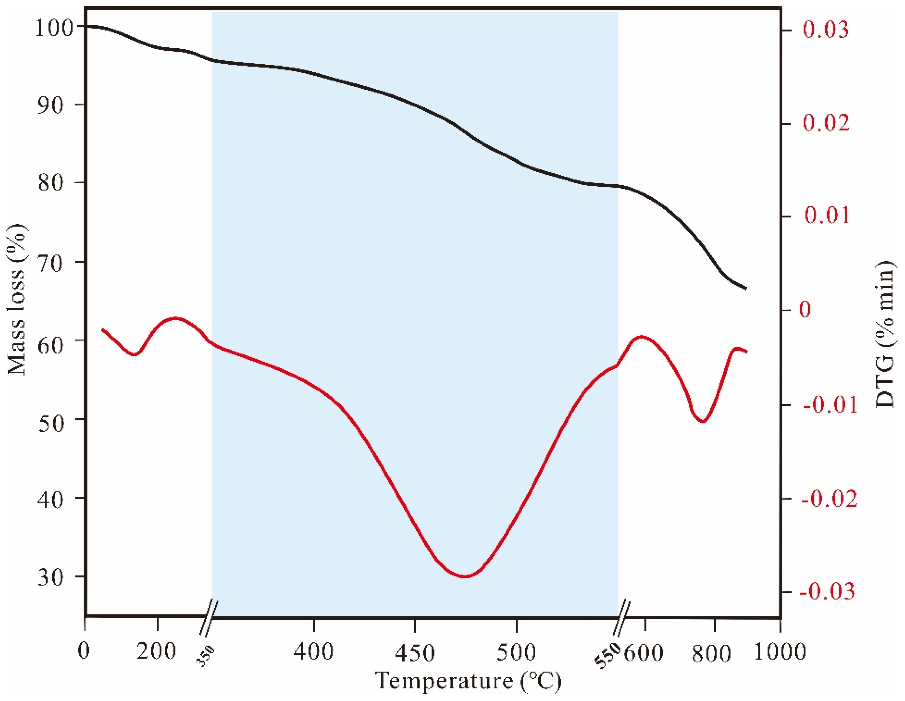
Figure 1. TG (black line) and DTG (red line) curves of oil shale (modified from [25]).
Energies 16 04386 g001
Figure 2. Evolution of the mass contents of pyrolytic products from s typical kerogen with Easy%Ro [7].
Energies 16 04386 g002
Figure 3. Macroscale 3D surface scanning of (a) fracture development and (b) micro-CT scans of microfractures and pore development during the heating of Minhe oil shale [17]. (ah) in (a,b) Scanned images of samples at temperatures of 185, 300, 350, 400, 440, 475, 500, and 520 °C, respectively.
Energies 16 04386 g003
Figure 4. Porosity and permeability (PEBP) of oil shale and solid residues [18]. K represent permeability (PEBP).
Energies 16 04386 g004
Figure 5. Schematic diagram of Shell’s ICP [34]. Black wavy arrows represent the flow direction of oil and gas. Red horizontal lines represent the flow channel of oil and gas.
Energies 16 04386 g005
Figure 6. Shale in situ convection technology using injected superheated steam (MTI) [37]. Red horizontal lines represent fractures during the hydraulic fracturing process. The blue and red arrows represent the flow direction of gas.
Energies 16 04386 g006
Figure 7. Optical photos of half-sections of samples after in situ conversion experiments with ATS [44]. (a) High-temperature nitrogen with a gas flow of 65 L/min is used for heat injection. After preheating the sample to 300 °C using high-temperature nitrogen with a gas flow of 40 L/min, ambient temperature oxygen-containing gas with a constant flow rate (5 L/min-21% O2 for (b) and 5 L/min-16% O2 for (c)) is injected to trigger the autothermic reaction. The red arrows represent the injection direction of gas. (1) Residual zone after the oxidation reaction; (2) autothermic zone undergoing the exothermic reaction; (3) incomplete conversion zone without exothermic oxidation reaction.
Energies 16 04386 g007
Figure 8. Calculated oil and gas yields during ICP of the Chang 7 shale at different heating rates [7]. (ad) Calculated oil and gas yields at heating rates of 0.5, 1, 5, and 10 °C/d, respectively.
Energies 16 04386 g008
Figure 9. (a) Cumulative oil production and the production period of different well patterns; (b) energy ratio and predominance period of different well patterns [11].
Energies 16 04386 g009
Figure 10. Schematic of the method of water stopping via gas flooding [89].
Energies 16 04386 g010
Table 1. Summary of the classification and status of oil shale in situ conversion technologies.
Heating MethodProcessLast StatusReference
ConductionIn situ conversion process (ICP)Demonstration[19,20,28]
ElectrofracTMPlanned field experiment[20,29]
Geothermic fuel cell (GFC)Laboratory simulation[20,30,31]
High voltage—power frequency electric heating (HVF)Laboratory simulation[32,33]
ConvectionCRUSHAbandon[20,34]
CCRAbandon[34]
In situ vapor extraction (IVE)Field experiment[20,35]
MTIPlanned field experiment[20,36,37,38,39,40]
Near-critical water (NCW)Field experiment[34,35,41]
ReactionTure in situ (TIS)Abandon[20,42,43]
Modified in situ (MIS)Abandon[20,42,43]
Autothermic pyrolysis in situ conversion (ATS)Field experiment[18,44,45]
Reaction heat of calcium oxide and waterThesis[46]
RadiantRadio frequency and supercritical fluid (RF/CF)Laboratory simulation[20,47]
MicrowavePlanned field experiment[20,47,48]
Disclaimer/Publisher’s Note: The statements, opinions and data contained in all publications are solely those of the individual author(s) and contributor(s) and not of MDPI and/or the editor(s). MDPI and/or the editor(s) disclaim responsibility for any injury to people or property resulting from any ideas, methods, instructions or products referred to in the content.