Review

Comprehensive Review on Thin Film Homojunction Solar Cells: Technologies, Progress and Challenges

1
Department of Electronics and Communications, Faculty of Engineering, Ain Shams University, Cairo 11566, Egypt
2
Department of Communications and Electronics, Engineering School, Canadian International College (CIC), Giza 12577, Egypt
3
Nanotechnology and Nanoelectronics Engineering Department, UST at Zewail City, Giza 12578, Egypt
4
Department of Basic Engineering Sciences, Benha Faculty of Engineering, Benha University, Benha 13511, Egypt
5
Engineering Physics and Mathematics Department, Faculty of Engineering, Ain Shams University, Cairo 11566, Egypt
6
Department of Computer Engineering, College of Computer Science and Engineering, University of Ha’il, Ha’il 55211, Saudi Arabia
7
Department of Electrical Communication and Electronics Systems Engineering, Faculty of Engineering, Modern Science and Arts University (MSA), Cairo 12556, Egypt
8
Faculty of Engineering, Arab Academy for Science and Technology (AAST), Cairo 11736, Egypt
9
Center of Excellence in Nanotechnology, Arab Academy for Science and Technology and Maritime Transport, El-Alamein 51718, Egypt
*
Author to whom correspondence should be addressed.
Energies 2023, 16(11), 4402; https://doi.org/10.3390/en16114402
Submission received: 10 April 2023 / Revised: 15 May 2023 / Accepted: 26 May 2023 / Published: 30 May 2023
(This article belongs to the Special Issue Modeling and Simulation of Solar Cells)

Abstract

:
With the aim of achieving high efficiency, cost-effectiveness, and reliability of solar cells, several technologies have been studied. Recently, emerging materials have appeared to replace Si-based cells, seeking economic fabrication of solar cells. Thin-film solar cells (TFSCs) are considered strong candidates for this mission, specifically perovskite-based solar cells, reporting competitive power convergence efficiencies reaching up to 25.7%. Substantial efforts have been invested in experimental and research work to surpass the Si-based cells performance. Simulation analysis is a major tool in achieving this target by detecting design problems and providing possible solutions. Usually, a TFSC adopts p-i-n heterojunction architecture by employing carrier transport materials along with the absorber material in order to extract the photogenerated electrons and holes by realizing a built-in electric field. Eventually, this dependency of conventional heterojunction TFSCs on carrier transport layers results in cost-ineffective cells and increases the possibility of device instability and interface problems. Thus, the design of p-n homojunction TFSCs is highly desirable as an essential direction of structural innovation to realize efficient solar cell operation. In this review, a summary of the fundamentals of TFSC materials, recent design and technology progress, and methodologies for improving the device performance using experimental research studies will be discussed. Further, simulation analysis will be provided by demonstrating the latest research work outcomes, highlighting the major achievements and the most common challenges facing thin film homojunction solar cell structures and the methods to improve them.

1. Introduction

Numerous studies have been carried out in order to produce renewable and ecofriendly energy resources. Amongst the available alternatives, solar energy provides sustainable, and clean energy at a moderate cost. Solar energy is directly converted to electricity using solar cells. Various solar cell technologies involving wafer-based, thin-film, organic, and hybrid have been researched to achieve high efficiency, cost-effectiveness, and reliability. One of the preferable solar cell technologies is crystalline silicon (c-Si) solar cells that show high power conversion efficiency (PCE) [1,2,3,4]. In addition to its high PCE (26.7% for a single junction), the c-Si solar cells are popular due to their material abundance, non-toxicity, durability, and the p-n homojunction structures, which are free from interface issues [5]. On the other hand, c-Si suffers from high manufacturing costs compared to some other solar cell technologies.
Several materials have been investigated as alternative absorber materials to accomplish low-cost and high-PCE solar devices [6]. In this regard, thin-film solar cells (TFSCs) established from chalcogenides materials, such as CIGS, CdTe, CTSe and CISe, have been intensively studied and have reached the commercialization phase [1]. Additionally, other candidates are being researched, such as CZTSe and Sb2Se3 [7,8] because of their enhanced absorption coefficient; variable bandgap; and outstanding stability [9,10]. Besides the aforementioned inorganic thin-film technologies, dye-sensitized solar cell (DSSC) was introduced. The DSSC uses organic dyes as light absorbers. The advantages of DSSCs lie in their high flexibility and low production cost [11]. On the other side, DSSCs have met challenges that are being faced to make the device structure suitable for all weather conditions [12]. Additionally, DSSCs have low PCE compared to other technologies [13].
Amongst TFSCs, perovskite (PVK)-based solar cells are considered promising solar cells owing to their rapidly increasing efficiency. This type of solar cell consists of a hybrid between organic and inorganic lead (Pb), or tin (Sn) halide-based elements utilized as active materials [14]. The PVK materials have drawn immense interest for photovoltaic applications because of their remarkable properties, such as high absorption coefficient, long carrier diffusion length and tunable bandgap [15,16,17,18]. PVK cells have shown great improvement in PCE from 3.8% in 2009 [19] to 25.7% in 2022 [20,21] regarding the single-junction architecture. This remarkable rise in PCE puts PVK solar cells at the forefront of emerging photovoltaics [15,22].
Accordingly, TFSCs are very promising candidates for energy harvesting applications. Considerable research studies have been conducted to further enhance their performance. In that context, modeling and simulation of TFSCs play a very important role in studying the new functionalities and physics phenomena of new targeted materials that can be used as absorber materials of TFSCs. In addition, simulation helps to understand various absorber materials’ potentials and limitations for various device applications. Since the simulation phase predicts the performance of the cells to be enhanced before the fabrication phase, which in turn saves time and cost, it is therefore important to utilize simulation software to design efficient solar cells and to propose novel structures.
In a heterojunction solar cell, TFSCs contain a hole transport layer (HTL) and an electron transport layer (ETL) to create an electric field that is responsible for the separation of photogenerated carriers. Nevertheless, utilizing such layers increases the production cost and complexity in addition to producing interface issues due to recombination losses and mismatch between the different materials. The development of p-n homojunction TFSCs can effectively boost the built-in electric field, which, in turn, improves cell performance without facing interface problems. Several studies have focused on the development of perovskite p-n homojunction solar cells. Cui et al. introduced the physical fundamentals of perovskite p-n homojunctions [23]. In a concise review, N. Ali et al. examined the structure and fabrication of homojunction solar cells, with a particular focus on materials such as Cu2O, CuInS2, InGaN, and InP [24]. Sun et al. provided a mini review that focused solely on perovskite solar cells. Their work examined the experimental analysis of p/n-type perovskite materials, chemical composition, and device architecture [25].
In this review, we perform a detailed review on thin-film solar cells in general, with specific highlight on perovskite solar cells among the thin-film solar cells, with respect to fundamentals of structure layers, various materials used, recent design and technology progress, methodologies for improving device performance using experimental studies, and discussing the most common challenges in fabrication and performance. Additionally, our unique contribution is the survey of simulation analysis studied that demonstrates the latest research outcomes and effect of different design parameters on performance while highlighting the major achievements and challenges. We expect that this review can offer a reference for homojunction TFSCs and pave the path for more development for these types of promising device categories.
In the coming sections, a brief description of TFSCs and their progress is presented. The TFSCs, using emerging and promising active materials, such as PVK, SnS and Sb2Se3, are experimentally and theoretically demonstrated alongside simulation work results. Afterwards, some challenges and concerns of p-n homojunction TFSCs that should be taken into consideration in order to enhance its PCE will be discussed, showing how the simulations can present an insight vision to overcome the challenges by detecting the problems and resolving them, paving the way to improve the performance of the solar cell. Finally, we briefly discuss some of the fabrication challenges associated with one of the most widely promoted TFSCs (PVK TFSCs), as well as how to surmount these challenges.

2. Heterojunction Thin-Film Solar Cells

Conventional heterojunction TFSCs are made by employing multiple thin film layers of photovoltaic elements onto a substrate. The thickness of the thin film layer can vary from several nanometers to a few of micrometers, which is remarkably thinner than traditional c-Si cells [26]. This makes TFSCs smaller in mass, lower in resistance, and less prone to abrasion [13,27]. In general, there are two possible configurations for the TFSC structure, as shown in Figure 1. The first configuration (Figure 1a) allows light to enter the device through the opposite side of the substrate “film side”. In this type of configuration, the substrate can be opaque or transparent, and it has to sustain the mechanical stability of the cell. For this configuration, the design started with a transparent conducting oxide (TCO) as a top contact, through which the light enters the device followed by the ETL, absorber layer, the HTL, and the rear contact. These layers are deposited on the top of the substrate. The second possibility is to invert the layer stack (inverted structure) by starting the structure with the superstrate, as shown in Figure 1b. In a superstrate configuration, the HTL layer is deposited on the TCO-coated substrate, while the rear electrode is deposited on the ETL. Here, since the illuminated light penetrates the cell via the superstrate, the superstrate must be particularly transparent.
By the illustration of Figure 1, a TFSC employs an absorber layer between two selective contacts or buffering layers (ETL and HTL). Two approaches were developed to deposit the absorber layer: (1) the vacuum-based deposition method and (2) the solution-based deposition approach. The vacuum-based deposition approach includes different techniques, such as sputtering, evaporation, and pulsed-laser deposition, while solution-based deposition involves developed techniques with high functionality, such as spin-coating, sol-gel, spray pyrolysis, chemical bath deposition, and screen-printing [28,29,30,31]. It is worth noting that the solution-based deposition approach offers great potential for simple fabrication and low-cost solar cells; however, it suffers from a lower stability compared to those fabricated by vacuum-based deposition approach [32,33]. For an efficient charge collection, the absorber material should have high mobility and a low recombination rate. ETL and HTL have a significant role in reducing the interfacial recombination between the absorber and the contacts. It should be as thin as possible to decrease transport resistance while being thick enough to prevent effective charge recombination from being hampered [34]. It is worth mentioning that the buffering layers should have large bandgaps to prevent surface charge recombination [35]. Further, to increase the capture efficiency of the incident light, and hence increase the PCE, the front and/or back surfaces are textured to reduce the surface reflection of the incident light [36,37,38]. Finally, the photogenerated carriers are collected by the front and back contacts of the device. Table 1 summarizes the role of each layer along with its requirements in both configurations (either substrate or superstrate TFSC).
As mentioned herein, the most rapidly developing photovoltaic technology is the perovskite TFSC. Therefore, the remainder of this section will be devoted to PVK TFSCs. Actually, the performance of PVK TFSCs depends on their structure, which is determined by selecting appropriate materials and deposition techniques. Normally, a PVK TFSC consists of a perovskite absorber material sandwiched between two buffer layers, such as ETL and HTL, to facilitate charge transfer between the perovskite absorber film and the front and rear contacts. PVK TFSC designs can be classified into two categories: (1) mesoporous or (2) planar architectures, depending on whether the cell type includes a mesoporous oxide material or not. Moreover, PVK TFSCs can be categorized into two distinct arrangements depending on the current direction: (1) conventional n-i-p (substrate configuration), and (2) inverted p-i-n (superstrate configuration), as shown in Figure 1.
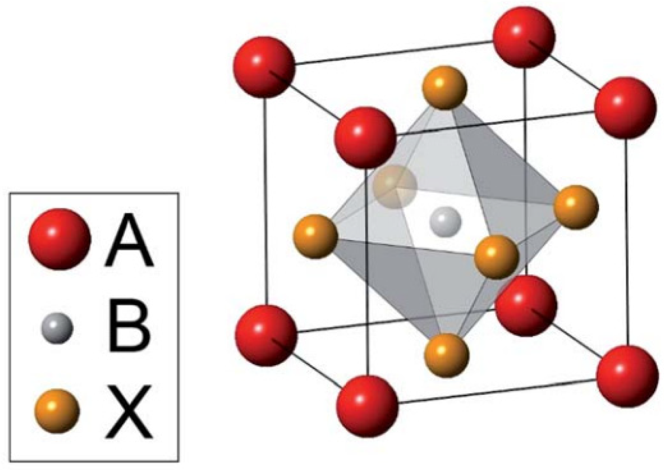
The perovskite material needs to be properly selected and constructed to maximize solar cell efficiency. In general, the perovskites have the formula ABX3, where A and B are the organic–inorganic cations, and X is the halide. Figure 2 depicts the crystal structure of the PVK material. Tuning the size of the A cation is critical for achieving charge neutrality within the lattice [39,40], while modifying the length of the B-X bond has been shown to be significant in defining the bandgap [41].The most commonly used absorber materials in perovskite solar cells include single-halide PVKs, such as MAPbI3 and MAPbBr3, while mixing halides to form, for example, MAPbI3-xBrx or MAPbI3-xClx achieves bandgap tunability, which can be altered by varying the composition (x) in the perovskite material. Mixed-halide PVKs display varied PV performance and stability depending on the halide ratio because of its modified structural and optical characteristics [42]. As an example, MAPbI3-xClx has a greater diffusion length (which is about 1 micron) than MAPbI3 (about 100 nm); therefore, a fabricated device that employs MAPbI3−xClx as an absorber material demonstrates a higher PCE compared to those using MAPbI3 as an absorber material [43].
During the design of perovskite solar cells, one can optimize the absorber layer thickness to be consistent with the diffusion length of the PVK material [44]. Furthermore, the cation A can be modified from methylammonium (MA) to other materials, such as formamidinium (FA) or Cesium (Cs), to form a perovskite structure. Some efforts have been made to develop a mixed cation PVK using the formamidinium and methylammonium cations. An increased stability and a PCE improvement of more than 18% has been accomplished due to this method [45,46,47]. Similarly, Cs-FA-MA triple-cation-based PVK TFSCs reported a high PCE of up to 20.8%, with higher current density [48]. Moreover, lead (Pb) is a toxic metal in nature and unsafe. To alleviate the toxicity issues, different materials, such as nontoxic tin (Sn), bismuth (Bi) and germanium (Ge), are used as alternatives to Pb [49,50]. However, compared to lead-based PVK solar cells, the PCE observed by Pb-free PVK-based solar cells is still inferior [51,52,53,54]. Therefore, the endeavors to substitute the lead metal need more efforts due to the poor PCE.
To guarantee successful carrier collection, the material to be employed in ETL and HTL must have the necessary band alignment with respect to the photoactive film [55,56]. To satisfy the required band alignment, a variety of materials can be used as transport layers, which can be organic or inorganic. The most popular material for HTL is spiro-OMeTAD, which costs ten times higher than the cost of the gold and platinum [57]. Moreover, some studies indicate that using organic materials for HTL can cause poor stability for the perovskite solar cells. An inorganic HTL seems to be a good alternative because of its low cost and intrinsic chemical stability [58,59]. The transport layer materials should be carefully selected to ensure there is less contact between them and the perovskite film to reduce charge carrier recombination. Various inorganic materials that can be used as an HTL, such as nickel oxide (NiO) [59,60,61], cuprous oxide (Cu2O) and cupric oxide (CuO) [62,63,64], copper indium disulfide (CuInS2) [65,66], and copper zinc tin sulfide (CZTS) [67]. Additionally, ETL makes a substantial contribution to the PCE and device stability. TiO2, ZnO, CdS, PCBM, SnO2, and other materials [68,69,70,71,72,73] are examples of ETLs. The most often used ETL material now is SnO2. Compared with TiO2, SnO2 has higher mobility, wider bandgap, and superior optical transmittance [74]. This leads to the enhancement of collecting and transporting charge carriers.
The improvement in the PCE of the PVK TFSCs is notably limited by the carrier recombination mechanisms in the PVK film itself or interfaces between the layers, even when employing heterojunction architectures. Therefore, it is mandatory to minimize the carrier recombination rates inside the perovskite film to improve the performance of the cell. One technique is to improve the fabrication processes and thereby decrease defect sites in PVK layers [75,76,77]. Other strategies, such as compositional engineering [45,47] and alternative architecture design [78,79,80], have been investigated to minimize the carrier recombination losses. Recently, ETL-free or HTL-free PVK TFSCs have been demonstrated to have good potential due to their advantages of simple architectures and easy manufacturing. In such a case, the perovskite material can be used as an absorber layer and a carrier transport layer, simultaneously, thanks to its ambipolar transport characteristics; however, the PCE measured using structures without ETL or HTL is still not as significant since the recombination probability increases [81,82,83].

3. Homojunction Thin-Film Solar Cells

Extensive research is essential to enhance the PCE of solar cells by gaining an in-depth understanding of their physics and equivalent modeling. Numerical simulations can predict the impact of physical modifications on device performance and test the viability of novel design concepts without actual production. One new route that has utilized numerical simulation to understand and study the underlying mechanism is the p-n homojunction structure. For instance, the perovskite material by itself can form a homojunction structure owing to its unique self-doping characteristic, which leads to minimizing the usage of external impurities that causes the formation of carrier recombination centers [84,85]. Moreover, PVK-based homojunctions can leverage the strong experience and technology established in conventional inorganic solar cells, such as Si-based homojunctions, thus offering promising future potential. In the following sections, the fundamentals of the perovskite p-n homojunctions will be investigated along with previous experimental and theoretical works.

3.1. Perovskite p-n Homojunction

In this subsection, the basic architecture and fundamentals of the PVK p-n homojunction are presented. Further, experimental studies and developments in this field are introduced. Additionally, findings on cell performance optimization and the structural design of PVK p-n homojunctions using simulation analysis are discussed, giving theoretical guidance for this type of TFSC.

3.1.1. Fundamentals of Perovskite p-n Homojunction

As mentioned earlier, the physical basics underlying p-n junctions have been explored for years, resulting in the invention of most PV cells based on traditional inorganic semiconductors, such as silicon and gallium arsenide. The perovskite p-n homojunction is comprised of two PVK films of distinct (or opposite) doping categories, one is n-type and the other is p-type, which are joined together at the junction. While the solution method can be utilized in preparing the first film, it cannot be used to prepare the second film since this would destroy the first layer. In addition, perovskite can be produced by the double-source evaporation system [86]. The realization of a certain electrical doping type of the perovskite material can be achieved by either intrinsic defects or extrinsic doping [87]. The intrinsic defects can be induced by different methods, such as growth conditions [88,89], and the proportion of the precursor components [90]. For instance, n-type doping can be produced from MAPbI3 layers with Pb2+-rich/MA+-deficient/I-deficient precursors, while p-type doping can be achieved with MA+-rich/Pb2+-deficient. Further, the intrinsic defects or self-doping can be controlled by the temperature and time of the annealing treatment [88,91]. On the other hand, extrinsic doping involves the insertion of impurity atoms into the crystal atoms. The introduction of some elements, such as sodium, copper, and oxygen, can create acceptor impurities under iodide-rich and lead-poor conditions [92]. Additionally, n-doping can be attained by the partial substitution of lead in PVK with tin or antimony, or the partial composition of iodide by chlorine [93]. Thus, the intrinsic and extrinsic defects are appropriate methods to adjust the carrier concentration and, hence, Fermi levels in perovskites.
The PVK p-n homojunction is then integrated into the perovskite-based standard planar structure by either substrate or superstrate architecture (Figure 3a provides an example to the superstrate architecture). As displayed in Figure 3a, the PVK p-n homojunctions offer an additional built-in electric field in the absorber material, where the holes and electrons transfer toward HTL and ETL, respectively. This extra field induces the adapted transportation of the photo-generated current, thus lowering the carrier recombination rates. Additionally, the value of the open-circuit voltage for such a cell depends on quasi-Fermi-level splitting ( E F n E F p ) of the PVK under illumination, where E F n and E F p are the quasi-Fermi levels of electron and holes in the n- and p-region of the perovskite p-n homojunction. The quasi-Fermi levels are determined by the doping concentration of both regions, photo-generation, and the recombination of charges [94]. With increasing photo-generation, the quasi-Fermi levels shift closer to the conduction and valence bands, and the open-circuit voltage is increased. Regarding recombination, the deep-level trap states in the forbidden band will hinder quasi-Fermi splitting, thus dramatically limiting the open-circuit voltage improvement [95]. The energy level diagram of the PVK-based p-n homojunction is shown in Figure 3b, and the main carrier flow mechanisms are illustrated in the figure. When the incident photons are captivated by the n-type and p-type layers, the resultant charge carriers are created in both films. Then, the electron and holes will drift in opposite paths. After that, the electrons are injected into the ETL and transferred to the front contact while the holes are injected into the HTL and collected at the back contact.

3.1.2. Recent Progress in Perovskite p-n Homojunction

Here, the recent progress and development in perovskite p-n homojunction, experimentally and theoretically, are reviewed. In the experimental subsection, the studies start with the initial thoughts for designing and developing the perovskite p-n homojunction. Then, some of the efforts to boost the performance of the PVK homojunction cells are presented, including: (i) surface modification of perovskite film, (ii) utilizing graded bandgap perovskites, and (iii) simplifying the architecture of the perovskite homojunctions. Next, tremendous effort had been taken in order to pave the way to achieve some important aims in the simulation of perovskite p-n homojunction, such as studying and exploring the features of some emerging and promising active materials, investigating the design of PVK TFSCs with/without one or both of HTL/ETL, and studying the bandgap gradient of the active materials and the influence of variation design parameters on the cell performance. The simulation studies are presented in the upcoming subsection.
A. 
Experimental Progress
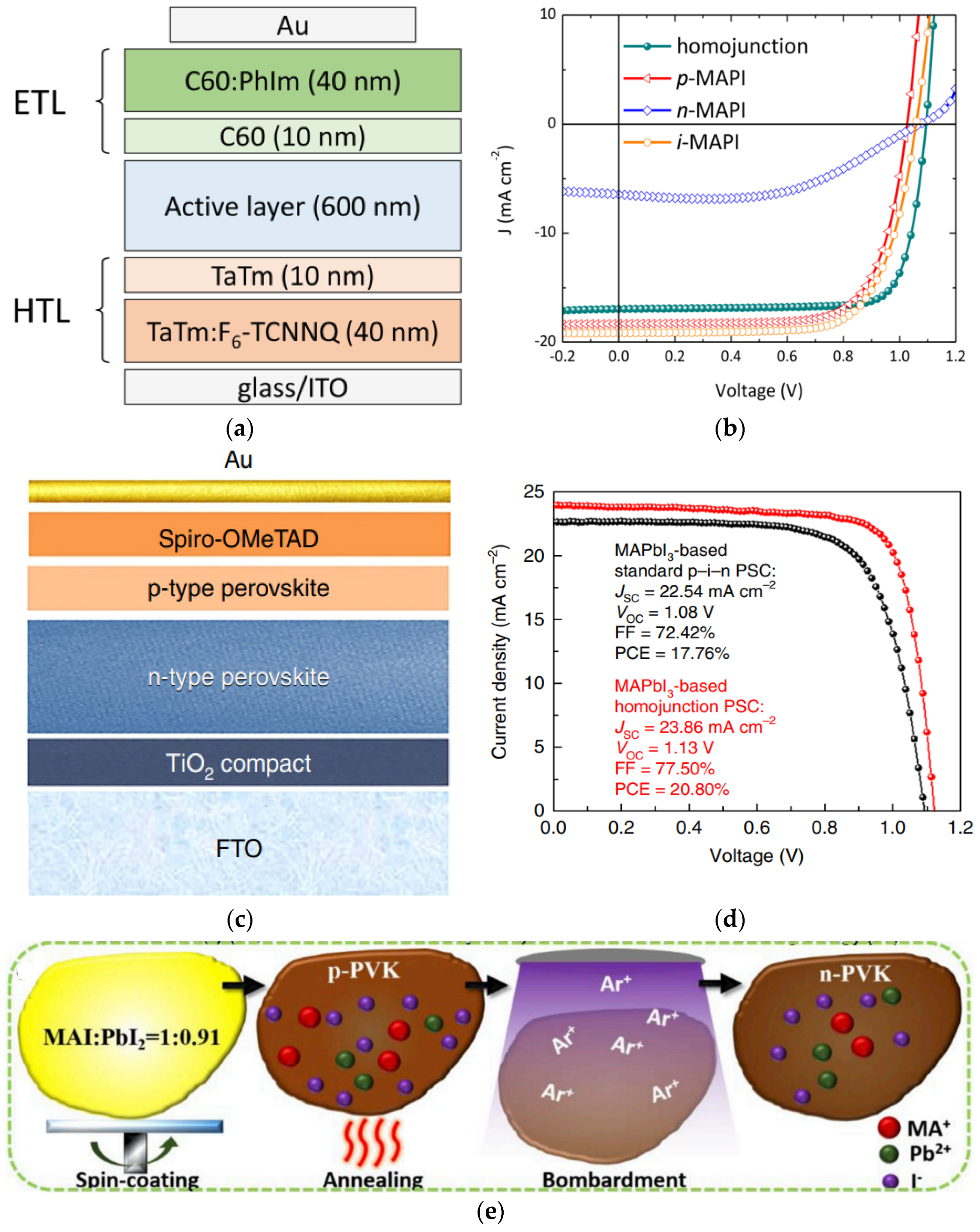
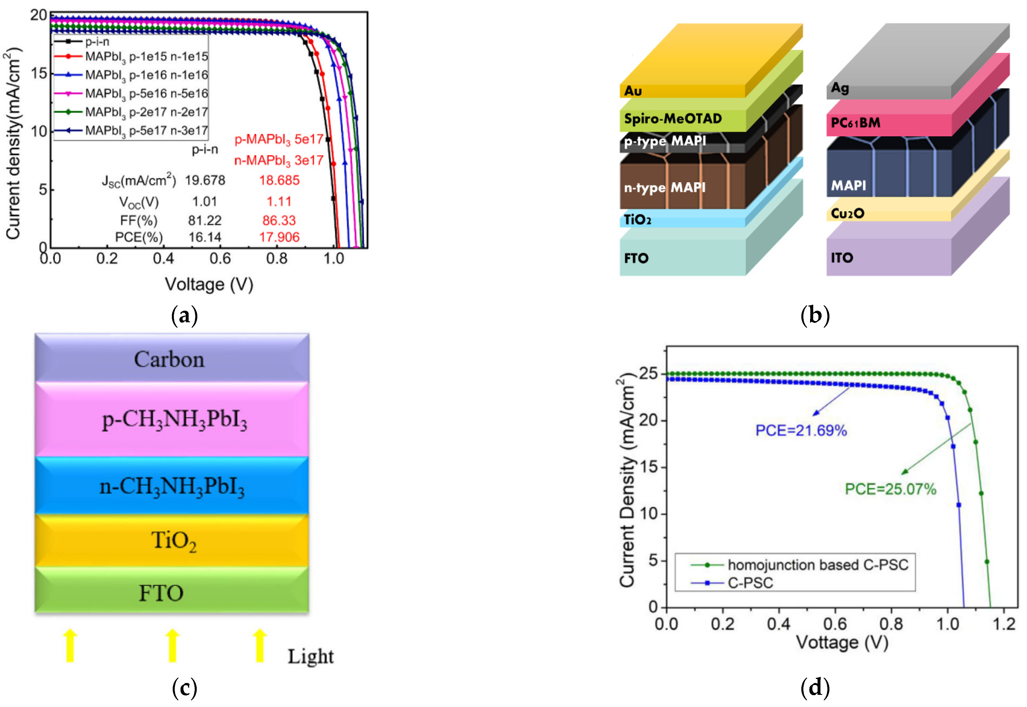
The perovskite p-n homojunctions have been implemented experimentally and successfully developed using different fabrication and design techniques, proving to possess significant potential for variety of applications. In 2018, Danekamp et al., utilized the vacuum deposition of stoichiometrically tuned MAPbI3 to prepare the perovskite p-n homojunction [85]. Then, they integrated the perovskite p-n homojunction (of a 600 nm thickness) with carrier transport materials to establish the planar perovskite p-n homojunction solar cell. Figure 4a depicts a general schematic layout of such perovskite solar cell. Different types of active layers had been utilized, such as p-type perovskite, intrinsic perovskite, n-type perovskite and perovskite p-n homojunction. In comparison with fabricated devices using a p-type, i-type or n-type absorber (using the same environmental conditions), a limited short-circuit current of 16.8 mA/cm2 is achieved by the homojunction structure (see Figure 4b) [85]. In addition, the device with p-n homojunction showed a decent charge extraction and reduced recombination rates, as evident from the higher fill factor (80%) and higher open-circuit voltage (1.1 V). In another context, Cui et al., have used a mixed deposition technique that combines one-step spin-coating and vacuum vapor deposition to realize the perovskite p-n homojunction [96]. Figure 4c illustrates the perovskite thin film with a homojunction composed of p-type and n-type PVK films, as designed by Cui et al. This structure showed an enhanced PCE over the conventional p-i-n architecture due to the directed carrier flow and reduced recombination losses owing to the increased built-in electric field. The authors utilized two different perovskite materials: MAPbI3 and FA0.15MA0.85PbI3. A certified PCE exceeding 20%, which is 3% higher than its corresponding p-i-n configuration, was achieved in the MAPbI3 homojunction cells due to the rise in both open-circuit voltage and short-circuit current (see Figure 4d). Moreover, FA0.15MA0.85PbI3 homojunctions are examined and incorporated into perovskite solar cells, resulting in efficiencies of up to 21.38%.
As mentioned earlier, extrinsic doping can adjust the carrier concentration and the position of the Fermi level in PVKs that form perovskite homojunctions, which can be used to modify the surface of the perovskite film. In addition, a methodology to regulate the majority carrier type based on extrinsic doping has been reported by Chang et al., which contributed to the performance optimization of PVK TFSCs. They incorporated alkali elements, such as Na+, K+, and Rb+, into the PVK film and demonstrated its influence on the majority carrier type of the PVK layer [97]. They found that doping perovskite with alkali can convert the undoped PVK film from an undoped n-type to a doped p-type. Further, Ren et al. modified the surface properties of PVK layers by Ar+ bombardment (Figure 3e), causing in situ n-type doping at the surface of p-type PVKs, which enhanced the self-powered photo-response of perovskite film [98].
Figure 4. (a) Schematic of the perovskite thin-film solar cell utilized by Danekamp et al., where the active layer varied among p-type, i-type, n-type, each of a thickness 600 nm, and p-n homojunction with a thickness 600 nm; each type has a thickness of 300 nm [85], (b) JV curves under illumination for the solar cell of (a) [85], (c) the perovskite p-n homojunction fabricated by Cui et al. which is composed of p-type and n-type perovskite layers [96], (d) JV curves of the perovskite p-n homojunction realized by Cui et al. [96], and (e) representative diagram process of Ar+ bombardment to induce an n-type perovskite [98].
Energies 16 04402 g004
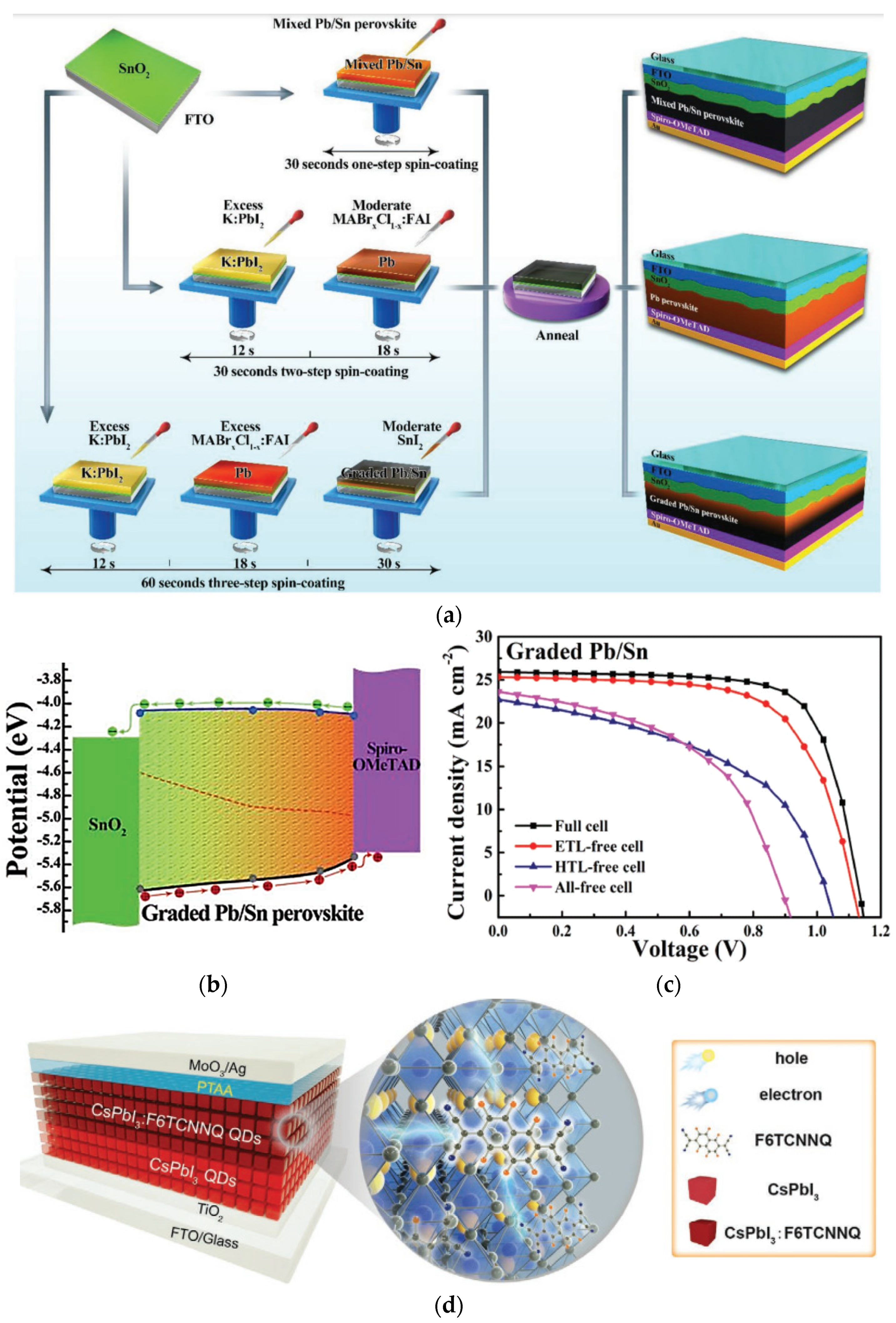
Additionally, the electric field augmentation caused by the graded junction design is an efficient way for facilitating carrier transport in PVK TFSCs. Sun et al. realized a perovskite p-n homojunction with a graded bandgap using a simple three-step dynamic spin-coating technique (Figure 5a). Using electrical doping, they were able to achieve a gradually decreasing PVK bandgap, starting at 1.53 eV on the side facing the light and decreasing to 1.27 eV on the other side as the doping changed from n-type to p-type (Figure 5b) [99]. The development of a graded bandgap perovskite homojunction fostered oriented carrier transport in PVK TFSCs and diminished reliance on the ETL and HTL (Figure 5c). Additionally, Xiang et al. established a quadruple-cation perovskite layer, which formed many graded perovskite homojunctions, and a PCE of 22.0% has been obtained [100].
Recently, Yuan et al. regulated the bandgap of the inorganic perovskite CsPbI3 quantum dots (PQDs) by controlling their size [101]. They designed a gradient band alignment (GBA) homojunction made of three films of PQDs with various bandgaps to generate an aligned gradient energy profile. A high open-circuit voltage of 1.25 V and a PCE of 13.2% have been reached [101]. In addition, Zhang et al. developed a PVK p-n homojunction to demonstrate an efficient quantum dots photovoltaics with the thickness of the absorber over 1.2 μm (Figure 5d) [102]. A champion efficiency of 15.29% is achieved by the p-n homojunction’s realization of a broader depletion area, which also makes charge transfer easier and decreases carrier recombination.
Figure 5. (a) Illustrative diagram of fabrication processes of mixed Pb/Sn perovskite, Pb-based perovskite, and graded Pb/Sn perovskite, reproduced from Sun et al. [99], (b) the energy band diagram of the graded Pb/Sn perovskite [99], (c) JV characteristics of perovskite solar cells with various cell structures based on graded Pb/Sn perovskite [99], and (d) a complete p-n homojunction device that is fabricated using pristine CsPbI3 QDs and F6TCNNQ-doped CsPbI3 QDs [102].
Energies 16 04402 g005
Carrier transport layers, either ETL or HTL, in the conventional perovskite heterojunction architectures play a remarkable role in extracting the photo-generated holes and electrons. Eliminating one or both of these layers can degrade the performance of such cells. However, PVK homojunctions can attain the extraction and transportation of the photo-induced carriers without the carrier transport layers via the induced built-in field created by the homojunction. Consequently, the direct conjunction of the homojunction and contacts may produce a basic device without the ETL and HTL, eliminating the costly organic materials [87]. In this context, Cui et al. attempted to eliminate the ETL and HTL in order to build a simple solar cell with a completely independent homojunction and a PCE of about 8% [96]. In the same manner, Sun et al. pointed out that the dependency of the perovskite homojunction on the carrier transport layer had been weakened. They designed a PVK TFSC with an ETL-free configuration that showed a PCE of 18.7% and an HTL-free type with a PCE of 11.1%. When both the ETL and HTL were removed, the recorded PCE was 10.3% [99]. Although the device structure is simplified, the interface recombination becomes a serious problem due to the direct contact between the metal electrode and the PVK layer, limiting cell performance. The problems of interfacial breakage, metal ion transport and carrier recombination are inevitable. Accordingly, the simplified devices need to be further optimized for improved performance using interface engineering, defect passivation, dopant concentration management, and other methods.
A summary of some experimental perovskite p-n homojunction is listed in Table 2. The table illustrates the structure of the cell when it is conventional (utilizing both an ETL and HTL), ETL-Free, HTL-Free, or CTL-free. Additionally, the method used to design each perovskite p-n homojunction solar cells, along with an indication of the electrical performance of each cell, is presented.
B. 
Progress in Modeling and Simulation of PVK TFSCs
Aside from the experimental investigations stated above, numerical simulations are useful for expecting the performance of PVK TFSCs and may be used to further identify the features of PVK homojunctions. A collection of software packages is accessible in order to examine the solar cell performance (whether single-junction or tandem cells), incorporating Silvaco [103], SCAPS [104], COMSOL [105], and wxAMPS [106]. The operational assumption of any simulation tool is based on concurrently solving semiconductor transport equations and Poisson’s equation on a predefined mesh.
Using the SCAPS 1D and based on the structure of perovskite p-n homojunction cell reported by Cui et al. [96], T. Kirchartz, and D. Cahen conducted a theoretical investigation on the doping effect on the performance of PVK TFSCs [107]. According to the design specifications reported in [96], they found, using the aid of band diagrams of PVK TFSCs, that the doping densities of n-type and p-type perovskites measured using the Hall effect (ND = 8 × 1012 cm−3 and NA = 8 × 109 cm−3), as reported in [96], are not sufficient for creating the p-n junction. Their finding relies on two important criteria. The first criterion is that the doping concentrations of the two layers of a p-n homojunction have to be at certain levels in such a way as to guarantee that the depletion width produced by the doping must be significantly smaller than the total photoactive film thickness. According to this criterion, a minimum doping density of 1 × 1016 cm−3, given the reported absorber layer thickness of 500 nm, was calculated. Even with a density of 8 × 1012 cm−3, the highest doping concentration reported in [96], the minimum thickness of the depletion width is 20 μm, which is much wider than the thickness of PVK TFSCs. The second criterion is the product of the doping densities of n-type (ND) and p-type (NA) must exceed the product of charge carrier concentrations, n and p, at the maximum power point. At the maximum power point, the product np ≈ 6.1 × 1024 cm−6 (reported in [96]) is higher than the maximum value of the product (NDNA ≈ 6.4 × 1022 cm−6). Thus, they concluded that 1016 cm−3 donor and acceptor concentrations would have been capable of fulfilling both conditions.
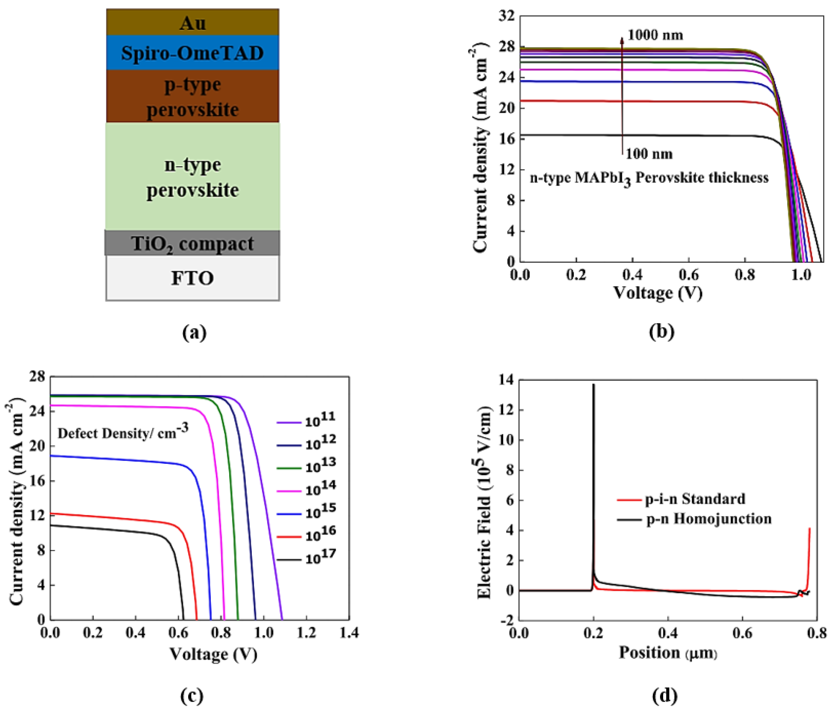
In this way, several researchers have gone on to investigate the influence of doping concentration and other parameters, emphasizing the relevance of simulation in understanding and analyzing cell performance. To optimize the performance of the PVK-based homojunction TFSCs, Sengar et al. started with experimentally verified device models (see Figure 6a) to investigate the effects of the thickness of the junction, the electric field, and the defect density on the performance of the homojunction PVK TFSC by simulation using SCAPS [108]. They reported that increasing the thickness of n-type absorber has a positive impact on short-circuit current, however, it decreases the open-circuit voltage (see Figure 6b). On the other hand, increasing the defect density deteriorates both the short-circuit current and open-circuit voltage (see Figure 6c). Further, a greater electric field in the homojunction can reduce the charge carrier recombination losses (see Figure 6d). With the help of open-circuit voltage and short-circuit current enhancement, their simulation results have showed a PCE value of 23.52%, which is higher than its counterpart of the heterojunction-based devices, thanks to low defect density and higher electric field.
Furthermore, Li et al. thoroughly analyzed the impact of various materials for ETLs and HTLs, absorber layer thickness, and interface defect concentrations on the performance of perovskite homojunction TFSCs [109]. They optimized the performance by using TiO2 and Spiro-OMeTAD as ETL and HTL materials, respectively. Moreover, the defect density of the p-type PVK and the thickness of absorber have been optimized. The efficiency of an optimized cell can reach 27.10% [109], demonstrating the substantial performance of the homojunction cell. In addition, He et al. reported and analyzed the effect of doping perovskite absorbers in a p-n homojunction (Figure 7a) using three different types of HTL: NiO, Si, and Spiro-OMeTAD [110]. Among the three different materials, the NiO showed the best performance, even when compared to a p-i-n cell utilizing the same materials applied as HTLs. Finally, they reported that homojunction PVK TFSCs enhanced the built-in potential and supports the improvement in the open-circuit voltage, thereby increasing the PCE. Moreover, Maram et al. introduced a proposed inverted p-n homojunction structure utilizing an ultra-thin HTL (Figure 7b), reporting a PCE of 13% [111]. The proposed cell is based on a reported structure [96]. In addition, they have revealed the importance of using various inorganic HTL materials, such as CuAlO2, due to their chemical and thermal stabilization, cheapness, and high transparency in comparison to organic HTL material. Utilizing CuAlO2 as an HTL for the inverted p-n homojunction cell resulted in a PCE of 16.48%.
All the previous simulation studies relied on investigating variations in certain parameters to optimize the performance of PVK p-n homojunction TFSCs; however, some theoretical research studies have gone to investigate homojunction p-n PVK TFSCs differently. One of these studies involved omitting the use of an HTL and/or ETL. Lin et al. built an HTL-free carbon-based perovskite homojunction model (Figure 7c) to discuss the influence of perovskite doping densities, thickness values, carrier mobilities, and defect densities on the cell performance using SCAPS simulator [112]. In this study, the authors obtained an optimized PCE greater than 25%, which is considerably exceptional to conventional HTL-free PSCs (Figure 7b).
Furthermore, Y. Da and M. Xie simulated four different configurations, including a standard n-i-p solar cell, ETL-free n-i-p solar cell, HTL-free cell, and perovskite p-n homojunction solar cell by omitting the carrier transport layers (Figure 8a) [113]. They then compared its performance with that of n-i-p, ETL-free n-i-p, and HTL-free n-i-p structures (Figure 8b,c). They reported that the all-free p-n homojunction solar cell introduced the greatest PCE (26.3%) among all different structures by optimizing its electrical and optical properties [113]. In the same line of thought, Khan et al. utilized a SCAPS simulator to realize a PVK TFSC by omitting both the ETL and HTL with significant charge extraction potential [114]. They have studied and optimized the influence of some important parameters of the p-type layer on the performance of PVK TFSCs, such as the defect density, charge-harvesting capability, and acceptor density. Additionally, they optimized the charge transport at the interface of the p-type and the carbon electrode. Following the previous optimization technique, a PCE of 15.6% has been achieved.
Moreover, some researchers have studied the effect of the graded doping concentration of the absorber film using simulations. In this context, R. Yousuf and G. Qazi designed a uniformly and non-uniformly doped perovskite absorber film on p-n homojunction perovskites as TCO/WS2/MAPbI3(n)/MAPbI3(p)/MoO3/Metal (Figure 8d) [115]. Their study reveal that the electric field induced by the non-uniform doping concentration has the same direction of the electric field generated by the p-n junction and are therefore constructively added together. They found that the grading in the doping of absorber layer improved the electric field, which enhanced the performance parameters of the PVK TFSC by 7.48% to record a PCE of 28.26%.
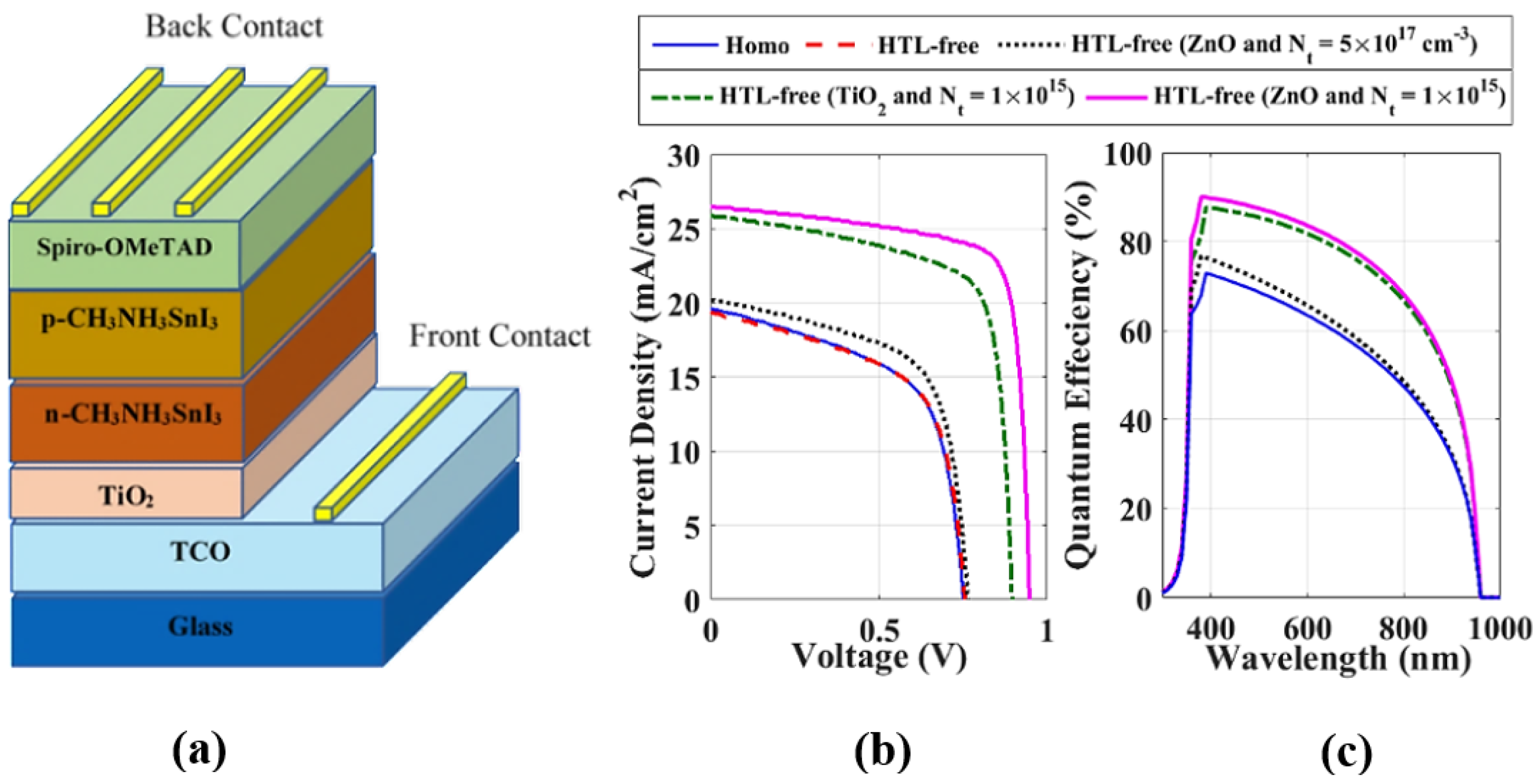
Recently, the interest in designing and simulating PVK TFSCs with emerging materials, especially lead-free materials, has increased as the lead-based perovskite materials suffer from the toxic nature of lead, which hinders their commercialization. Tin (Sn), germanium (Ge), and other candidates are alternate metals for replacing lead in perovskite structures [54,116,117,118,119]. Most of the research studies investigated the lead-free perovskite materials in heterojunction structures [120,121,122,123,124,125,126,127,128]; however, the p-n homojunction-based lead-free PVK TFSC exploration still requires more attention to attain the optimum material for perovskite with/without an ETL and/or HTL. The first study to examine a lead-free hybrid hetero-homojunction PVK TFSC was carried out by M.S. Salem et al. [129]. They presented a lead-free hybrid hetero-homojunction PVK TFSC based on an n-type MASnI3/p-type MASnI3 (Figure 9a). The cell working flow was thoroughly investigated using SCAPS for numerical analysis. In addition, the HTL-free cell was optimized considering doping, work function of the back contact, and defect density. Further, they utilized different ETL materials, such as ZnO and TiO2, at different defect density. When utilizing HTL-free structure with ZnO as an ETL (Figure 9b,c), a PCE of 19.37% was obtained. Finally, Table 3 lists the available studies that simulated and modeled PVK p-n homojunction solar cells, showing the best performance analysis for each cell.

3.2. Other Candidates for p-n Homojunction

It is important to investigate earth-abundant and nontoxic photoactive materials to achieve eco-friendly solar cells. In this context, a lot of effort has been put forward to introduce new materials as emerging absorber candidates, such as SnS and Sb2Se3 [10,130]. Kawanishi et al. fabricated, for the first time, an SnS-based p-n homojunction TFSC by the deposition of a p-type SnS layer on a single Cl-doped n-type SnS crystal. They achieved an open-circuit voltage of 360 mV and a PCE of 1.4% [131]. The open-circuit voltage can be further enhanced by reducing the recombination losses due to the defects in the p-type SnS. The short-circuit current can also be enhanced by improving the design of such cells so that more light can be absorbed by the n-type SnS. In addition, Sb2Se3 has attracted considerable scientific interest in recent years as cost-effective PV material. Liang et al. implemented an effective ion-doping technique to boost the performance of Sb2Se3-based TFSCs [130]. They prepared Sn-doped and I-doped Sb2Se3 by magnetron sputtering, enabling the first fabrication of the substrate structure of an Sb2Se3 quasi-homojunction TFSC with an arrangement of Mo/Sb2Se3-Sn/Sb2Se3-I/ITO/Ag (Figure 10a). This cell recorded a PCE of more than 2% (see Figure 10b), clearly demonstrating the potential and the need for further exploration. Further, Ren et al. built a TFSC based on Cu-doped (p-type) and I-doped (n-type) Sb2Se3 using magnetron sputtering [10]. They studied the influence of absorber thickness on the carrier lifetime, diffusion length, and trap density. A thicker absorber layer led to an enhancement in charge carrier collection efficiency, a longer electron diffusion length, and a lower defect concentration. They obtained the following cell performance parameters: VOC of 294 mV, JSC of 20 mA/cm2, FF of 41%, and PCE of 2.41%. These results again demonstrate the need for more research.
Theoretically, Shaker et al. utilized Sb2Se3 to construct and thoroughly investigate a non-toxic hybrid hetero-homojunction and homojunction TFSC (Figure 11a) [1]. To optimize the cell performance, they examined the effect of the thickness and the doping concentration of the two types of absorber materials. When the optimization of the absorber parameters was performed, PCE values of 7.75%, 10.08% and 8.79% had been achieved for CdS-based, ZnOS-based, and homojunction TFSCs, respectively (Figure 11b) [1].
Another line of thought is to consider another promising material, such as SnS, as an absorber material in TFSCs that can be embedded to form and design perovskite-based tandem cells. In this context, Farshad Jafarzadeh et al. reported a PCE of 23.3% for an SnS homojunction TFSC by optimizing the thicknesses, carrier concentrations, and defect density of the absorber layer [132]. After that, they successfully implemented a tandem perovskite solar cell utilizing an SnS p-n homojunction cell as the bottom cell. The current matching between the top and bottom cells was successfully achieved (Figure 11c). Additionally, they reported that most of the photon energy at shorter wavelengths is absorbed in the PVK sub-cell and those at the longer wavelengths in the SnS sub-cell (Figure 11d). Finally, they achieved a PCE of 28.92% for the tandem solar cell. Table 4 summarizes some experimental and theoretical studies for new candidates for p-n homojunctions.

4. Challenges of PVK TFSCs

For perovskite solar cell material designs, there are several important challenges and considerations that should be taken into account. For PVK TFSC fabrication, various low-cost methods are generally used, such as spin-coating, sequential deposition, doctor blade, Inkjet printing, hybrid chemical vapor deposition, and dip-coating. Most high-PCE PVK TFSCs are fabricated using spin-coating [133,134]. However, it is not commercially viable for large-sized solar cell fabrication mainly due to loss of uniformity [134]. A variety of substitute methods for depositing the PVK TFSC layers is available and have been investigated to achieve requirements, such as uniformity and defect-free crystals. In addition, the PVK inner composition, particularly the perovskite layer itself, is highly sensitive to the ambient atmosphere (presence of oxygen and the relative humidity level). Therefore, building an industrial establishment to successively deposit the perovskite device layers while preserving an inert atmosphere is quite complicated and expensive. Consequently, the selection of moisture- and oxygen-resistant layers is a step toward simplifying and reducing the cost of the manufacturing process [134].
On the perovskite materials level, they benefit from the exceptional ability to regulate their physical properties, including the thin film phenomenon and direct bandgap. In this context, p- or n-type PVK layers can be fabricated by defect engineering, using self-doping by means of engineering the precursor compositions and process circumstances, or by extrinsic doping achieved through introducing impurity atoms to the crystal. Perovskite materials have possible high doping densities for improved electric fields, yet the increase in doping density escalates defect density. It is essential to find the balance between higher doping and lower defect density. This involves discovering more proper PVK self-doping and extrinsic doping approaches [87]. While simplifying the device structure by removing the ETL and HTL, interfacial recombination becomes severe due to the direct contact between electrode and PVK layer, limiting cell performance. Thus, it is compulsory to further optimize the simple device with interfacial engineering and defect passivation.
In general, with the continuous progress in development of PVK solar cells, the short operational lifetime under environmental conditions is a main challenge impeding commercialization [133]. It is then necessary to understand the degradation mechanisms of a PSC device in order to overcome the stability challenges. Degradation mechanisms can be divided mainly into two categories according to the cause: intrinsic and extrinsic [134]. Intrinsic degradation is correlated to the cell process, including defects on crystal structure and reactivity between adjacent layers, whereas extrinsic degradation is related to the environmental factors, such as moisture, oxygen, high temperatures, ultraviolet radiation, and exposure to outside air, that all directly contribute to several degradations at the device level, occurring at several interfaces concurrently [135]. High temperatures can easily cause the degradation of the perovskite crystal structure and phase [136]. In order to enhance the stability of PSCs, several factors must be taken into account, including material engineering, novel device structure design, HTM and ETM layer, and electrode materials’ preparation and encapsulation method. To sum up, Table 5 provides a summary to illustrate the challenges of PVK TFSCs.

5. Conclusions

In this review, conventional heterojunction TFSCs, specifically PVK TFSCs, alongside their advantages and drawbacks are investigated. One of these drawbacks is the recombination losses, particularly at the interface between the absorber and the carrier transport layers, which push the research into omitting the carrier transport layers even though it affects the observed PCE. Homojunction TFSCs are considered a fresh route to overcome the recombination losses and hence improve the performance of the TFSCs. In this context, the fundamentals of p-n homojunctions, especially the perovskite p-n homojunction, alongside their experimental and theoretical progress are deeply reviewed; however, we believe that some new absorbers candidates, such as SnS and Sb2Se3, can pave the way for solar cells that are more efficient, abundant in nature, and environmentally benign.
Additionally, this review argues that numerical simulations are an essential methodology for testing the viability of a novel technology. Furthermore, by using numerical simulations, the effect of physical and technical aspects on device performance can be easily examined. Despite the presence of some previous efforts, we think that further extensive research is still needed to find the best material for lead-free perovskite p-n homojunctions, along with the presence or absence of a ETL and/or HTL. Further, bandgap grading is another effective technique to simplify the design of perovskite p-n homojunction, which had been intensively studied by experiments while its simulation study needs more effort.

Author Contributions

Conceptualization, T.M.A., A.S., A.Z. and M.A.; investigation, O.M.S., M.S.S. and M.F.; writing—original draft preparation, O.M.S., Y.E., T.M.A. and A.S.; writing—review and editing, O.M.S., Y.E., T.M.A., A.S., M.A., M.S.S. and M.F.; supervision, A.Z. All authors have read and agreed to the published version of the manuscript.

Funding

This research received no external funding.

Data Availability Statement

Not applicable.

Acknowledgments

This paper is based upon work supported financially by the Arab Academy for Science, Technology and Maritime Transport under grant number (2059).

Conflicts of Interest

The authors declare no conflict of interest.

References

  1. Shaker, A.; Salem, M.S.; Deepthi Jayan, K. Analysis and Design of P-n Homojunction Sb2Se3 Solar Cells by Numerical Simulation. Sol. Energy 2022, 242, 276–286. [Google Scholar] [CrossRef]
  2. Salem, M.S.; Alzahrani, A.J.; Ramadan, R.A.; Alanazi, A.; Shaker, A.; Abouelatta, M.; Gontrand, C.; Elbanna, M.; Zekry, A. Physically Based Analytical Model of Heavily Doped Silicon Wafers Based Proposed Solar Cell Microstructure. IEEE Access 2020, 8, 138898–138906. [Google Scholar] [CrossRef]
  3. Salem, M.S.; Zekry, A.; Shaker, A.; Abouelatta, M. Design and Simulation of Proposed Low Cost Solar Cell Structures Based on Heavily Doped Silicon Wafers. In Proceedings of the 2016 IEEE 43rd Photovoltaic Specialists Conference (PVSC), IEEE, Portland, OR, USA, 5–10 June 2016; pp. 2393–2397. [Google Scholar]
  4. Green, M.A.; Dunlop, E.D.; Siefer, G.; Yoshita, M.; Kopidakis, N.; Bothe, K.; Hao, X. Solar Cell Efficiency Tables (Version 61). Prog. Photovolt. Res. Appl. 2023, 31, 3–16. [Google Scholar] [CrossRef]
  5. Saif, O.M.; Zekry, A.; Shaker, A.; Abouelatta, M.; Saeed, A. Efficient Self-Protected Thin Film c-Si Solar Cell against Reverse-Biasing Condition: A Simulation Study. In Proceedings of the 2022 IEEE 49th Photovoltaics Specialists Conference (PVSC), Philadelphia, PA, USA, 5–10 June 2022; pp. 336–338. [Google Scholar] [CrossRef]
  6. Lu, S.; Chen, C.; Tang, J. Possible Top Cells for Next-Generation Si-Based Tandem Solar Cells. Front. Optoelectron. 2020, 13, 246–255. [Google Scholar] [CrossRef]
  7. Nam, D.; Cho, S.; Sim, J.H.; Yang, K.J.; Son, D.H.; Kim, D.H.; Kang, J.K.; Kwon, M.S.; Jeon, C.W.; Cheong, H. Solar Conversion Efficiency and Distribution of ZnS Secondary Phase in Cu2ZnSnS4 Solar Cells. Sol. Energy Mater. Sol. Cells 2016, 149, 226–231. [Google Scholar] [CrossRef]
  8. Sun, H.; Sun, K.; Huang, J.; Yan, C.; Liu, F.; Park, J.; Pu, A.; Stride, J.A.; Green, M.A.; Hao, X. Efficiency Enhancement of Kesterite Cu2 ZnSnS4 Solar Cells via Solution-Processed Ultrathin Tin Oxide Intermediate Layer at Absorber/Buffer Interface. ACS Appl. Energy Mater. 2018, 1, 154–160. [Google Scholar] [CrossRef]
  9. Wang, X.; Tang, R.; Jiang, C.; Lian, W.; Ju, H.; Jiang, G.; Li, Z.; Zhu, C.; Chen, T. Manipulating the Electrical Properties of Sb2(S,Se)3 Film for High-Efficiency Solar Cell. Adv. Energy Mater. 2020, 10, 2002341. [Google Scholar] [CrossRef]
  10. Ren, D.; Chen, S.; Cathelinaud, M.; Liang, G.; Ma, H.; Zhang, X. Fundamental Physical Characterization of Sb2Se3-Based Quasi-Homojunction Thin Film Solar Cells. ACS Appl. Mater. Interfaces 2020, 12, 30572–30583. [Google Scholar] [CrossRef]
  11. Li, Y.; Huang, W.; Zhao, D.; Wang, L.; Jiao, Z.; Huang, Q.; Wang, P.; Sun, M.; Yuan, G. Recent Progress in Organic Solar Cells: A Review on Materials from Acceptor to Donor. Molecules 2022, 27, 1800. [Google Scholar] [CrossRef]
  12. Kowsar, A.; Rahaman, M.; Islam, M.S.; Imam, A.Y.; Debnath, S.C.; Sultana, M.; Hoque, M.A.; Sharmin, A.; Mahmood, Z.H.; Farhad, S.F.U. Progress in Major Thin-Film Solar Cells: Growth Technologies, Layer Materials and Efficiencies. Int. J. Renew. Energy Res. 2019, 9, 579–597. [Google Scholar] [CrossRef]
  13. Nayak, P.K.; Mahesh, S.; Snaith, H.J.; Cahen, D. Photovoltaic Solar Cell Technologies: Analysing the State of the Art. Nat. Rev. Mater. 2019, 4, 269–285. [Google Scholar] [CrossRef]
  14. Byranvand, M.M.; Otero-Martínez, C.; Ye, J.; Zuo, W.; Manna, L.; Saliba, M.; Hoye, R.L.Z.; Polavarapu, L. Recent Progress in Mixed A-Site Cation Halide Perovskite Thin-Films and Nanocrystals for Solar Cells and Light-Emitting Diodes. Adv. Opt. Mater. 2022, 10, 2200423. [Google Scholar] [CrossRef]
  15. Green, M.A.; Ho-Baillie, A.; Snaith, H.J. The Emergence of Perovskite Solar Cells. Nat. Photonics 2014, 8, 506–514. [Google Scholar] [CrossRef]
  16. Saki, Z.; Byranvand, M.M.; Taghavinia, N.; Kedia, M.; Saliba, M. Solution-Processed Perovskite Thin-Films: The Journey from Lab- to Large-Scale Solar Cells. Energy Env. Sci. 2021, 14, 5690–5722. [Google Scholar] [CrossRef]
  17. Saliba, M. Perovskite Solar Cells Must Come of Age: Developing Aging Standards Is Required for Industrialization. Science 2018, 359, 388–389. [Google Scholar] [CrossRef]
  18. Schmidt-Mende, L.; Dyakonov, V.; Olthof, S.; Ünlü, F.; Lê, K.M.T.; Mathur, S.; Karabanov, A.D.; Lupascu, D.C.; Herz, L.M.; Hinderhofer, A.; et al. Roadmap on Organic–Inorganic Hybrid Perovskite Semiconductors and Devices. APL Mater. 2021, 9, 109202. [Google Scholar] [CrossRef]
  19. Kojima, A.; Teshima, K.; Shirai, Y.; Miyasaka, T. Organometal Halide Perovskites as Visible-Light Sensitizers for Photovoltaic Cells. J. Am. Chem. Soc. 2009, 131, 6050–6051. [Google Scholar] [CrossRef]
  20. Min, H.; Lee, D.Y.; Kim, J.; Kim, G.; Lee, K.S.; Kim, J.; Paik, M.J.; Kim, Y.K.; Kim, K.S.; Kim, M.G.; et al. Perovskite Solar Cells with Atomically Coherent Interlayers on SnO2 Electrodes. Nature 2021, 598, 444–450. [Google Scholar] [CrossRef]
  21. Yoo, J.J.; Seo, G.; Chua, M.R.; Park, T.G.; Lu, Y.; Rotermund, F.; Kim, Y.-K.; Moon, C.S.; Jeon, N.J.; Correa-Baena, J.-P.; et al. Efficient Perovskite Solar Cells via Improved Carrier Management. Nature 2021, 590, 587–593. [Google Scholar] [CrossRef]
  22. Snaith, H.J. Perovskites: The Emergence of a New Era for Low-Cost, High-Efficiency Solar Cells. J. Phys. Chem. Lett. 2013, 4, 3623–3630. [Google Scholar] [CrossRef]
  23. Cui, P.; Qu, S.; Zhang, Q.; Liu, B.; Yan, L.; Du, S.; Wang, X.; Huang, H.; Ji, J.; Li, M. Homojunction Perovskite Solar Cells: Opportunities and Challenges. Energy Mater. 2022, 1, 100014. [Google Scholar] [CrossRef]
  24. Ali, N.; Ahmed, R.; Luo, J.T.; Wang, M.; Kalam, A.; Al-Sehemi, A.G.; Fu, Y.Q. Advances in Nanostructured Homojunction Solar Cells and Photovoltaic Materials. Mater. Sci. Semicond. Process. 2020, 107, 104810. [Google Scholar] [CrossRef]
  25. Sun, Y.; Chen, W.; Sun, Z. A Mini Review: Constructing Perovskite p-n Homojunction Solar Cells. Chin. Chem. Lett. 2022, 33, 1772–1778. [Google Scholar] [CrossRef]
  26. Efaz, E.T.; Rhaman, M.M.; Imam, S.A.; Bashar, K.L.; Kabir, F.; Mourtaza, M.E.; Sakib, S.N.; Mozahid, F.A. A Review of Primary Technologies of Thin-Film Solar Cells. Eng. Res. Express 2021, 3, 032001. [Google Scholar] [CrossRef]
  27. Chopra, K.L.; Paulson, P.D.; Dutta, V. Thin-Film Solar Cells: An Overview. Prog. Photovolt. Res. Appl. 2004, 12, 69–92. [Google Scholar] [CrossRef]
  28. Jilani, A.; Abdel-wahab, M.S.; Hosny Hammad, A.; Jilani, A. Advance Deposition Techniques for Thin Film and Coating. Mod. Technol. Creat. Thin-Film Syst. Coat. 2017, 2, 137–149. [Google Scholar] [CrossRef]
  29. Arce-Plaza, A.; Sánchez-Rodriguez, F.; Courel-Piedrahita, M.; Galán, O.V.; Hernandez-Calderon, V.; Ramirez-Velasco, S.; López, M.O. CdTe Thin Films: Deposition Techniques and Applications. In Coatings and Thin-Film Technologies; IntechOpen: London, UK, 2018. [Google Scholar] [CrossRef]
  30. Nwambaekwe, K.C.; John-Denk, V.S.; Douman, S.F.; Mathumba, P.; Yussuf, S.T.; Uhuo, O.V.; Ekwere, P.I.; Iwuoha, E.I. Crystal Engineering and Thin-Film Deposition Strategies towards Improving the Performance of Kesterite Photovoltaic Cell. J. Mater. Res. Technol. 2021, 12, 1252–1287. [Google Scholar] [CrossRef]
  31. Ashok, A.; Regmi, G.; Romero-Núñez, A.; Solis-López, M.; Velumani, S.; Castaneda, H. Comparative Studies of CdS Thin Films by Chemical Bath Deposition Techniques as a Buffer Layer for Solar Cell Applications. J. Mater. Sci. Mater. Electron. 2020, 31, 7499–7518. [Google Scholar] [CrossRef]
  32. Eberspacher, C.; Fredric, C.; Pauls and Jack Serra, K. Thin-Film CIS Alloy PV Materials Fabricated Using Non-Vacuum, Particles-Based Techniques. Thin Solid. Film. 2001, 387, 18–22. [Google Scholar] [CrossRef]
  33. Cheshmekhavar, A.H.; Mahjoub, A.R.; Fakhri, H.; Dehghani, M. An All Solution-Based Process for the Fabrication of Superstrate-Type Configuration CuInS 2 Thin Film Solar Cells. RSC Adv. 2015, 5, 97381–97390. [Google Scholar] [CrossRef]
  34. Senthil, T.S.; Kalaiselvi, C.R. New Materials for Thin Film Solar Cells. In Coatings and Thin-Film Technologies; IntechOpen: London, UK, 2019. [Google Scholar]
  35. Bandari, A. Perovskite Solar Cell Stability and Performance Improved by Optimizing Buffer Layers. Scilight 2020, 2020, 131101. [Google Scholar] [CrossRef]
  36. Fahr, S.; Kirchartz, T.; Rockstuhl, C.; Lederer, F. Approaching the Lambertian Limit in Randomly Textured Thin-Film Solar Cells. Opt. Express 2011, 19, A865. [Google Scholar] [CrossRef] [PubMed]
  37. Sai, H.; Jia, H.; Kondo, M. Impact of Front and Rear Texture of Thin-Film Microcrystalline Silicon Solar Cells on Their Light Trapping Properties. J. Appl. Phys. 2010, 108, 044505. [Google Scholar] [CrossRef]
  38. Rockstuhl, C.; Fahr, S.; Bittkau, K.; Beckers, T.; Carius, R.; Haug, F.-J.; Söderström, T.; Ballif, C.; Lederer, F. Comparison and Optimization of Randomly Textured Surfaces in Thin-Film Solar Cells. Opt. Express 2010, 18, A335. [Google Scholar] [CrossRef] [PubMed]
  39. Borriello, I.; Cantele, G.; Ninno, D. Ab Initio Investigation of Hybrid Organic-Inorganic Perovskites Based on Tin Halides. Phys. Rev. B 2008, 77, 235214. [Google Scholar] [CrossRef]
  40. Eperon, G.E.; Stranks, S.D.; Menelaou, C.; Johnston, M.B.; Herz, L.M.; Snaith, H.J. Formamidinium Lead Trihalide: A Broadly Tunable Perovskite for Efficient Planar Heterojunction Solar Cells. Energy Env. Sci. 2014, 7, 982. [Google Scholar] [CrossRef]
  41. Noh, J.H.; Im, S.H.; Heo, J.H.; Mandal, T.N.; Seok, S. Il Chemical Management for Colorful, Efficient, and Stable Inorganic–Organic Hybrid Nanostructured Solar Cells. Nano Lett. 2013, 13, 1764–1769. [Google Scholar] [CrossRef]
  42. Attique, S.; Ali, N.; Imran, T.; Rauf, S.; Khesro, A.; Ali, S.; Wang, W.; Khatoon, R.; Abbas, A.; Ullah khan, E.; et al. An Overview of the Pressure- and Strain-Induced Changes in the Structural and Optoelectronic Properties of Organometal Halide Perovskites. Solar Energy 2022, 239, 198–220. [Google Scholar] [CrossRef]
  43. Stranks, S.D.; Eperon, G.E.; Grancini, G.; Menelaou, C.; Alcocer, M.J.P.; Leijtens, T.; Herz, L.M.; Petrozza, A.; Snaith, H.J. Electron-Hole Diffusion Lengths Exceeding 1 Micrometer in an Organometal Trihalide Perovskite Absorber. Science 2013, 342, 341–344. [Google Scholar] [CrossRef]
  44. Roy, P.; Khare, A. Understanding the Strategies to Attain the Best Performance of All Inorganic Lead-free Perovskite Solar Cells: Theoretical Insights. Int. J. Energy Res. 2022, 46, 15881–15899. [Google Scholar] [CrossRef]
  45. Pellet, N.; Gao, P.; Gregori, G.; Yang, T.-Y.; Nazeeruddin, M.K.; Maier, J.; Grätzel, M. Mixed-Organic-Cation Perovskite Photovoltaics for Enhanced Solar-Light Harvesting. Angew. Chem. Int. Ed. 2014, 53, 3151–3157. [Google Scholar] [CrossRef]
  46. Gil-Escrig, L.; Dreessen, C.; Palazon, F.; Hawash, Z.; Moons, E.; Albrecht, S.; Sessolo, M.; Bolink, H.J. Efficient Wide-Bandgap Mixed-Cation and Mixed-Halide Perovskite Solar Cells by Vacuum Deposition. ACS Energy Lett. 2021, 6, 827–836. [Google Scholar] [CrossRef] [PubMed]
  47. Jeon, N.J.; Noh, J.H.; Yang, W.S.; Kim, Y.C.; Ryu, S.; Seo, J.; Seok, S. Il Compositional Engineering of Perovskite Materials for High-Performance Solar Cells. Nature 2015, 517, 476–480. [Google Scholar] [CrossRef] [PubMed]
  48. Singh, T.; Miyasaka, T. Stabilizing the Efficiency Beyond 20% with a Mixed Cation Perovskite Solar Cell Fabricated in Ambient Air under Controlled Humidity. Adv. Energy Mater. 2018, 8, 1700677. [Google Scholar] [CrossRef]
  49. Yang, S.; Fu, W.; Zhang, Z.; Chen, H.; Li, C.-Z. Recent Advances in Perovskite Solar Cells: Efficiency, Stability and Lead-Free Perovskite. J. Mater. Chem. A Mater. 2017, 5, 11462–11482. [Google Scholar] [CrossRef]
  50. Turkevych, I.; Kazaoui, S.; Ito, E.; Urano, T.; Yamada, K.; Tomiyasu, H.; Yamagishi, H.; Kondo, M.; Aramaki, S. Photovoltaic Rudorffites: Lead-Free Silver Bismuth Halides Alternative to Hybrid Lead Halide Perovskites. ChemSusChem 2017, 10, 3754–3759. [Google Scholar] [CrossRef]
  51. Wu, T.; Liu, X.; Luo, X.; Lin, X.; Cui, D.; Wang, Y.; Segawa, H.; Zhang, Y.; Han, L. Lead-Free Tin Perovskite Solar Cells. Joule 2021, 5, 863–886. [Google Scholar] [CrossRef]
  52. Jain, S.M.; Edvinsson, T.; Durrant, J.R. Green Fabrication of Stable Lead-Free Bismuth Based Perovskite Solar Cells Using a Non-Toxic Solvent. Commun. Chem. 2019, 2, 91. [Google Scholar] [CrossRef]
  53. Hoye, R.L.Z.; Brandt, R.E.; Osherov, A.; Stevanović, V.; Stranks, S.D.; Wilson, M.W.B.; Kim, H.; Akey, A.J.; Perkins, J.D.; Kurchin, R.C.; et al. Methylammonium Bismuth Iodide as a Lead-Free, Stable Hybrid Organic–Inorganic Solar Absorber. Chem. A Eur. J. 2016, 22, 2605–2610. [Google Scholar] [CrossRef] [PubMed]
  54. Abdelaziz, S.; Zekry, A.; Shaker, A.; Abouelatta, M. Investigation of Lead-Free MASnI3-MASnIBr2 Tandem Solar Cell: Numerical Simulation. Opt. Mater. 2022, 123, 111893. [Google Scholar] [CrossRef]
  55. Hussain, I.; Tran, H.P.; Jaksik, J.; Moore, J.; Islam, N.; Uddin, M.J. Functional Materials, Device Architecture, and Flexibility of Perovskite Solar Cell. Emergent Mater. 2018, 1, 133–154. [Google Scholar] [CrossRef]
  56. Minemoto, T.; Murata, M. Theoretical Analysis on Effect of Band Offsets in Perovskite Solar Cells. Sol. Energy Mater. Sol. Cells 2015, 133, 8–14. [Google Scholar] [CrossRef]
  57. Roy, P.; Ghosh, A.; Barclay, F.; Khare, A.; Cuce, E. Perovskite Solar Cells: A Review of the Recent Advances. Coatings 2022, 12, 1089. [Google Scholar] [CrossRef]
  58. Kung, P.; Li, M.; Lin, P.; Chiang, Y.; Chan, C.; Guo, T.; Chen, P. A Review of Inorganic Hole Transport Materials for Perovskite Solar Cells. Adv. Mater. Interfaces 2018, 5, 1800882. [Google Scholar] [CrossRef]
  59. Irwin, M.D.; Buchholz, D.B.; Hains, A.W.; Chang, R.P.H.; Marks, T.J. P-Type Semiconducting Nickel Oxide as an Efficiency-Enhancing Anode Interfacial Layer in Polymer Bulk-Heterojunction Solar Cells. Proc. Natl. Acad. Sci. USA 2008, 105, 2783–2787. [Google Scholar] [CrossRef]
  60. Alibabaei, L.; Luo, H.; House, R.L.; Hoertz, P.G.; Lopez, R.; Meyer, T.J. Applications of Metal Oxide Materials in Dye Sensitized Photoelectrosynthesis Cells for Making Solar Fuels: Let the Molecules Do the Work. J. Mater. Chem. A Mater. 2013, 1, 4133. [Google Scholar] [CrossRef]
  61. Seo, S.; Park, I.J.; Kim, M.; Lee, S.; Bae, C.; Jung, H.S.; Park, N.-G.; Kim, J.Y.; Shin, H. An Ultra-Thin, Un-Doped NiO Hole Transporting Layer of Highly Efficient (16.4%) Organic–Inorganic Hybrid Perovskite Solar Cells. Nanoscale 2016, 8, 11403–11412. [Google Scholar] [CrossRef]
  62. Yu, W.; Li, F.; Wang, H.; Alarousu, E.; Chen, Y.; Lin, B.; Wang, L.; Hedhili, M.N.; Li, Y.; Wu, K.; et al. Ultrathin Cu 2 O as an Efficient Inorganic Hole Transporting Material for Perovskite Solar Cells. Nanoscale 2016, 8, 6173–6179. [Google Scholar] [CrossRef]
  63. Chatterjee, S.; Pal, A.J. Introducing Cu2O Thin Films as a Hole-Transport Layer in Efficient Planar Perovskite Solar Cell Structures. J. Phys. Chem. C 2016, 120, 1428–1437. [Google Scholar] [CrossRef]
  64. Rao, H.; Ye, S.; Sun, W.; Yan, W.; Li, Y.; Peng, H.; Liu, Z.; Bian, Z.; Li, Y.; Huang, C. A 19.0% Efficiency Achieved in CuOx-Based Inverted CH3NH3PbI3−xClx Solar Cells by an Effective Cl Doping Method. Nano Energy 2016, 27, 51–57. [Google Scholar] [CrossRef]
  65. Lv, M.; Zhu, J.; Huang, Y.; Li, Y.; Shao, Z.; Xu, Y.; Dai, S. Colloidal CuInS2 Quantum Dots as Inorganic Hole-Transporting Material in Perovskite Solar Cells. ACS Appl. Mater. Interfaces 2015, 7, 17482–17488. [Google Scholar] [CrossRef]
  66. Santra, P.K.; Nair, P.V.; George Thomas, K.; Kamat, P.V. CuInS2-Sensitized Quantum Dot Solar Cell. Electrophoretic Deposition, Excited-State Dynamics, and Photovoltaic Performance. J. Phys. Chem. Lett. 2013, 4, 722–729. [Google Scholar] [CrossRef] [PubMed]
  67. Wu, Q.; Xue, C.; Li, Y.; Zhou, P.; Liu, W.; Zhu, J.; Dai, S.; Zhu, C.; Yang, S. Kesterite Cu2ZnSnS4 as a Low-Cost Inorganic Hole-Transporting Material for High-Efficiency Perovskite Solar Cells. ACS Appl. Mater. Interfaces 2015, 7, 28466–28473. [Google Scholar] [CrossRef] [PubMed]
  68. Chen, L.-C.; Tseng, Z.-L. ZnO-Based Electron Transporting Layer for Perovskite Solar Cells. In Nanostructured Solar Cells; InTech: London, UK, 2017. [Google Scholar]
  69. Han, J.; Kwon, H.; Kim, E.; Kim, D.-W.; Son, H.J.; Kim, D.H. Interfacial Engineering of a ZnO Electron Transporting Layer Using Self-Assembled Monolayers for High Performance and Stable Perovskite Solar Cells. J. Mater. Chem. A Mater. 2020, 8, 2105–2113. [Google Scholar] [CrossRef]
  70. Wessendorf, C.D.; Hanisch, J.; Müller, D.; Ahlswede, E. CdS as Electron Transport Layer for Low-Hysteresis Perovskite Solar Cells. Sol. RRL 2018, 2, 1800056. [Google Scholar] [CrossRef]
  71. Patil, P.; Mann, D.S.; Nakate, U.T.; Hahn, Y.-B.; Kwon, S.-N.; Na, S.-I. Hybrid Interfacial ETL Engineering Using PCBM-SnS2 for High-Performance p-i-n Structured Planar Perovskite Solar Cells. Chem. Eng. J. 2020, 397, 125504. [Google Scholar] [CrossRef]
  72. Assi, A.A.; Saleh, W.R.; Mohajerani, E. Investigate of TiO2 and SnO2 as Electron Transport Layer for Perovskite Solar Cells. AIP Conf. Proc. 2020, 2290, 050039. [Google Scholar] [CrossRef]
  73. Tavakoli, M.M.; Yadav, P.; Tavakoli, R.; Kong, J. Surface Engineering of TiO 2 ETL for Highly Efficient and Hysteresis-Less Planar Perovskite Solar Cell (21.4%) with Enhanced Open-Circuit Voltage and Stability. Adv. Energy Mater. 2018, 8, 1800794. [Google Scholar] [CrossRef]
  74. Zhao, P.; Lin, Z.; Wang, J.; Yue, M.; Su, J.; Zhang, J.; Chang, J.; Hao, Y. Numerical Simulation of Planar Heterojunction Perovskite Solar Cells Based on SnO2 Electron Transport Layer. ACS Appl. Energy Mater. 2019, 2, 4504–4512. [Google Scholar] [CrossRef]
  75. Zheng, X.; Chen, B.; Dai, J.; Fang, Y.; Bai, Y.; Lin, Y.; Wei, H.; Zeng, X.C.; Huang, J. Defect Passivation in Hybrid Perovskite Solar Cells Using Quaternary Ammonium Halide Anions and Cations. Nat. Energy 2017, 2, 17102. [Google Scholar] [CrossRef]
  76. Chen, H.; Wei, Z.; He, H.; Zheng, X.; Sing Wong, K.; Yang, S.; Chen, H.N.; Wei, Z.H.; Zheng, X.L.; Yang, S.H.; et al. Solvent Engineering Boosts the Efficiency of Paintable Carbon-Based Perovskite Solar Cells to Beyond 14%. Adv. Energy Mater. 2016, 6, 1502087. [Google Scholar] [CrossRef]
  77. Ahn, N.; Son, D.Y.; Jang, I.H.; Kang, S.M.; Choi, M.; Park, N.G. Highly Reproducible Perovskite Solar Cells with Average Efficiency of 18.3% and Best Efficiency of 19.7% Fabricated via Lewis Base Adduct of Lead(II) Iodide. J. Am. Chem. Soc. 2015, 137, 8696–8699. [Google Scholar] [CrossRef] [PubMed]
  78. Jeon, N.J.; Na, H.; Jung, E.H.; Yang, T.Y.; Lee, Y.G.; Kim, G.; Shin, H.W.; Il Seok, S.; Lee, J.; Seo, J. A Fluorene-Terminated Hole-Transporting Material for Highly Efficient and Stable Perovskite Solar Cells. Nat. Energy 2018, 3, 682–689. [Google Scholar] [CrossRef]
  79. Ball, J.M.; Lee, M.M.; Hey, A.; Snaith, H.J. Low-Temperature Processed Meso-Superstructured to Thin-Film Perovskite Solar Cells. Energy Env. Sci. 2013, 6, 1739–1743. [Google Scholar] [CrossRef]
  80. Jeng, J.-Y.; Chiang, Y.-F.; Lee, M.-H.; Peng, S.-R.; Guo, T.-F.; Chen, P.; Wen, T.-C. CH 3 NH 3 PbI 3 Perovskite/Fullerene Planar-Heterojunction Hybrid Solar Cells. Adv. Mater. 2013, 25, 3727–3732. [Google Scholar] [CrossRef] [PubMed]
  81. Ke, W.; Fang, G.; Wan, J.; Tao, H.; Liu, Q.; Xiong, L.; Qin, P.; Wang, J.; Lei, H.; Yang, G.; et al. Efficient Hole-Blocking Layer-Free Planar Halide Perovskite Thin-Film Solar Cells. Nat. Commun. 2015, 6, 6700. [Google Scholar] [CrossRef]
  82. Etgar, L.; Gao, P.; Xue, Z.; Peng, Q.; Chandiran, A.K.; Liu, B.; Nazeeruddin, M.K.; Grätzel, M. Mesoscopic CH 3 NH 3 PbI 3 /TiO 2 Heterojunction Solar Cells. J. Am. Chem. Soc. 2012, 134, 17396–17399. [Google Scholar] [CrossRef]
  83. Hu, M.; Liu, L.; Mei, A.; Yang, Y.; Liu, T.; Han, H. Efficient Hole-Conductor-Free, Fully Printable Mesoscopic Perovskite Solar Cells with a Broad Light Harvester NH2CHNH2PbI3. J. Mater. Chem. A 2014, 2, 17115–17121. [Google Scholar] [CrossRef]
  84. Cho, K.T.; Paek, S.; Grancini, G.; Roldán-Carmona, C.; Gao, P.; Lee, Y.; Nazeeruddin, M.K. Highly Efficient Perovskite Solar Cells with a Compositionally Engineered Perovskite/Hole Transporting Material Interface. Energy Env. Sci. 2017, 10, 621–627. [Google Scholar] [CrossRef]
  85. Dänekamp, B.; Müller, C.; Sendner, M.; Boix, P.P.; Sessolo, M.; Lovrincic, R.; Bolink, H.J. Perovskite–Perovskite Homojunctions via Compositional Doping. J. Phys. Chem. Lett. 2018, 9, 2770–2775. [Google Scholar] [CrossRef]
  86. Liu, M.; Johnston, M.B.; Snaith, H.J. Efficient Planar Heterojunction Perovskite Solar Cells by Vapour Deposition. Nature 2013, 501, 395–398. [Google Scholar] [CrossRef] [PubMed]
  87. Euvrard, J.; Yan, Y.; Mitzi, D.B. Electrical Doping in Halide Perovskites. Nat. Rev. Mater. 2021, 6, 531–549. [Google Scholar] [CrossRef]
  88. Cui, P.; Wei, D.; Ji, J.; Song, D.; Li, Y.; Liu, X.; Huang, J.; Wang, T.; You, J.; Li, M. Highly Efficient Electron-Selective Layer Free Perovskite Solar Cells by Constructing Effective p-n Heterojunction. Sol. RRL 2017, 1, 1600027. [Google Scholar] [CrossRef]
  89. Kim, J.; Lee, S.H.; Lee, J.H.; Hong, K.H. The Role of Intrinsic Defects in Methylammonium Lead Iodide Perovskite. J. Phys. Chem. Lett. 2014, 5, 1312–1317. [Google Scholar] [CrossRef]
  90. Wang, Q.; Shao, Y.; Xie, H.; Lyu, L.; Liu, X.; Gao, Y.; Huang, J. Qualifying Composition Dependent p and n Self-Doping in CH3NH3PbI3. Appl. Phys. Lett. 2014, 105, 163508. [Google Scholar] [CrossRef]
  91. Ralaiarisoa, M.; Busby, Y.; Frisch, J.; Salzmann, I.; Pireaux, J.J.; Koch, N. Correlation of Annealing Time with Crystal Structure, Composition, and Electronic Properties of CH3NH3PbI3−xClx Mixed-Halide Perovskite Films. Phys. Chem. Chem. Phys. 2016, 19, 828–836. [Google Scholar] [CrossRef]
  92. Shi, T.; Yin, W.-J.; Yan, Y. Predictions for P-Type CH3NH3PbI3 Perovskites. J. Phys. Chem. C 2014, 118, 25350–25354. [Google Scholar] [CrossRef]
  93. Stoumpos, C.C.; Malliakas, C.D.; Kanatzidis, M.G. Semiconducting Tin and Lead Iodide Perovskites with Organic Cations: Phase Transitions, High Mobilities, and Near-Infrared Photoluminescent Properties. Inorg. Chem. 2013, 52, 9019–9038. [Google Scholar] [CrossRef]
  94. Huang, J.; Yuan, Y.; Shao, Y.; Yan, Y. Understanding the Physical Properties of Hybrid Perovskites for Photovoltaic Applications. Nat. Rev. Mater. 2017, 2, 17042. [Google Scholar] [CrossRef]
  95. Luo, D.; Su, R.; Zhang, W.; Gong, Q.; Zhu, R. Minimizing Non-Radiative Recombination Losses in Perovskite Solar Cells. Nat. Rev. Mater. 2019, 5, 44–60. [Google Scholar] [CrossRef]
  96. Cui, P.; Wei, D.; Ji, J.; Huang, H.; Jia, E.; Dou, S.; Wang, T.; Wang, W.; Li, M. Planar p-n Homojunction Perovskite Solar Cells with Efficiency Exceeding 21.3%. Nat. Energy 2019, 4, 150–159. [Google Scholar] [CrossRef]
  97. Chang, C.; Zou, X.; Cheng, J.; Ling, T.; Yao, Y.; Chen, D. Applied Trace Alkali Metal Elements for Semiconductor Property Modulation of Perovskite Thin Films. Molecules 2019, 24, 4039. [Google Scholar] [CrossRef] [PubMed]
  98. Ren, L.; Wang, M.; Li, M.; Wang, S.; Wang, S.; Zhao, Y.; Iqbal, M.A.; Jin, K. Enhanced Self-Powered Photoresponse in Perovskite Films with in Situ Induced p-n Homojunction by Ar+ Bombardment. Opt. Mater. 2020, 100, 109687. [Google Scholar] [CrossRef]
  99. Sun, H.; Deng, K.; Xiong, J.; Li, L. Graded Bandgap Perovskite with Intrinsic n–p Homojunction Expands Photon Harvesting Range and Enables All Transport Layer-Free Perovskite Solar Cells. Adv. Energy Mater. 2020, 10, 1903347. [Google Scholar] [CrossRef]
  100. Xiang, Y.; Ma, Z.; Peng, X.; Li, X.; Chen, B.; Huang, Y. Constructing Graded Perovskite Homojunctions by Adding Large Radius Phenylmethylamine Ions for Sequential Spin-Coating Deposition Method to Improve the Efficiency of Perovskite Solar Cells. J. Phys. Chem. C 2020, 124, 20765–20772. [Google Scholar] [CrossRef]
  101. Yuan, J.; Bi, C.; Xi, J.; Guo, R.; Tian, J. Gradient-Band Alignment Homojunction Perovskite Quantum Dot Solar Cells. J. Phys. Chem. Lett. 2021, 12, 1018–1024. [Google Scholar] [CrossRef]
  102. Zhang, X.; Huang, H.; Ling, X.; Sun, J.; Jiang, X.; Wang, Y.; Xue, D.; Huang, L.; Chi, L.; Yuan, J.; et al. Homojunction Perovskite Quantum Dot Solar Cells with over 1 Μm-Thick Photoactive Layer. Adv. Mater. 2022, 34, 2105977. [Google Scholar] [CrossRef]
  103. Silvaco Inc. Atlas User’s Manual; Silvaco Inc.: Santa Clara, CA, USA, 2016. [Google Scholar]
  104. Burgelman, M.; Nollet, P.; Degrave, S. Modelling Polycrystalline Semiconductor Solar Cells. Thin Solid. Film. 2000, 361–362, 527–532. [Google Scholar] [CrossRef]
  105. COMSOL, Inc. COMSOL Multiphysics Reference Manual, Version 5.3. Available online: https://doc.comsol.com/5.3/doc/com.comsol.help.comsol/COMSOL_ReferenceManual.pdf (accessed on 12 March 2023).
  106. Liu, Y.; Sun, Y.; Rockett, A. A New Simulation Software of Solar Cells—WxAMPS. Sol. Energy Mater. Sol. Cells 2012, 98, 124–128. [Google Scholar] [CrossRef]
  107. Kirchartz, T.; Cahen, D. Minimum Doping Densities for p-n Junctions. Nat. Energy 2020, 5, 973–975. [Google Scholar] [CrossRef]
  108. Sengar, B.S.; Garg, V.; Kumar, A.; Dwivedi, P. Numerical Simulation: Design of High-Efficiency Planar p-n Homojunction Perovskite Solar Cells. IEEE Trans. Electron. Devices 2021, 68, 2360–2364. [Google Scholar] [CrossRef]
  109. Li, G.; Guo, F.; Zhou, X.; Xue, L.; Huang, X.; Xiao, Y. Performance Optimization of Homojunction Perovskite Solar Cells by Numerical Simulation. Superlattices Microstruct. 2021, 156, 106922. [Google Scholar] [CrossRef]
  110. He, Q.; Gu, H.; Zhang, D.; Fang, G.; Tian, H. Theoretical Analysis of Effects of Doping MAPbI into P-n Homojunction on Several Types of Perovskite Solar Cells. Opt. Mater. 2021, 121, 111491. [Google Scholar] [CrossRef]
  111. Maram, D.K.; Haghighi, M.; Shekoofa, O.; Habibiyan, H.; Ghafoorifard, H. A Modeling Study on Utilizing Ultra-Thin Inorganic HTLs in Inverted p-n Homojunction Perovskite Solar Cells. Sol. Energy 2021, 213, 1–12. [Google Scholar] [CrossRef]
  112. Lin, L.; Li, P.; Kang, Z.; Xiong, H.; Chen, Y.; Yan, Q.; Jiang, L.; Qiu, Y. Device Design of Doping-Controlled Homojunction Perovskite Solar Cells Omitting HTL and Exceeding 25% Efficiency. Adv. Theory Simul. 2021, 4, 2000222. [Google Scholar] [CrossRef]
  113. Da, Y.; Xie, M. Device Physics of Homojunction Perovskite Solar Cells: A Design Omitting All the Charge Transport Layers with Efficiency Exceeding 26.3%. J. Phys. D Appl. Phys. 2022, 55, 285102. [Google Scholar] [CrossRef]
  114. Khan, D.; Sajid, S.; Khan, S.; Park, J.; Ullah, I. Identifying the Potentials for Charge Transport Layers Free N-p Homojunction-Based Perovskite Solar Cells. Sol. Energy 2022, 238, 69–77. [Google Scholar] [CrossRef]
  115. Yousuf, R.; Qazi, G. Numerical Modelling: Design and Investigation of Uniformly and Non-Uniformly Doped Absorber Layer Based PN Homojunction Perovskite Solar Cell Variants. Sol. Energy 2021, 228, 427–438. [Google Scholar] [CrossRef]
  116. Tripathi, M.; Vaibhav Mishra, V.; Sengar, B.S.; Ullas, A.V. Lead-Free Perovskite Solar Cell ByUsing SCAPS-1D: Design and Simulation. Mater. Today Proc. 2022, 62, 4327–4331. [Google Scholar] [CrossRef]
  117. Tariq Jan, S.; Noman, M. Influence of Layer Thickness, Defect Density, Doping Concentration, Interface Defects, Work Function, Working Temperature and Reflecting Coating on Lead-Free Perovskite Solar Cell. Sol. Energy 2022, 237, 29–43. [Google Scholar] [CrossRef]
  118. Saikia, D.; Bera, J.; Betal, A.; Sahu, S. Performance Evaluation of an All Inorganic CsGeI3 Based Perovskite Solar Cell by Numerical Simulation. Opt. Mater. 2022, 123, 111839. [Google Scholar] [CrossRef]
  119. Deepthi Jayan, K.; Sebastian, V. Comprehensive Device Modelling and Performance Analysis of MASnI3 Based Perovskite Solar Cells with Diverse ETM, HTM and Back Metal Contacts. Sol. Energy 2021, 217, 40–48. [Google Scholar] [CrossRef]
  120. Anik, M.H.K.; Mahmud, S.; Islam, M.A.; Talukder, H.; Biswas, S.K.; Islam, S. Comparative Performance Analysis and Material Exploration of ECO-Friendly Highly Efficient Perovskite Solar Cells. Semicond. Sci. Technol. 2022, 37, 115004. [Google Scholar] [CrossRef]
  121. Abdelaziz, S.; Zekry, A.; Shaker, A.; Abouelatta, M. Investigating the Performance of Formamidinium Tin-Based Perovskite Solar Cell by SCAPS Device Simulation. Opt. Mater. 2020, 101, 109738. [Google Scholar] [CrossRef]
  122. Kumar, M.; Raj, A.; Kumar, A.; Anshul, A. Effect of Band-Gap Tuning on Lead-Free Double Perovskite Heterostructure Devices for Photovoltaic Applications via SCAPS Simulation. Mater. Today Commun. 2021, 26, 101851. [Google Scholar] [CrossRef]
  123. Pindolia, G.; Shinde, S.M.; Jha, P.K. Optimization of an Inorganic Lead Free RbGeI3 Based Perovskite Solar Cell by SCAPS-1D Simulation. Sol. Energy 2022, 236, 802–821. [Google Scholar] [CrossRef]
  124. Ahmad, K.; Khan, M.Q.; Kim, H. Simulation and Fabrication of All-Inorganic Antimony Halide Perovskite-like Material Based Pb-Free Perovskite Solar Cells. Opt. Mater. 2022, 128, 112374. [Google Scholar] [CrossRef]
  125. El aallaoui, N.; Oukarfi, B.; Zazoui, M. Numerical Study of Inorganic Cs2TiBr6 Solar Cells with a Double Hole Transport Layers. Mater. Today Proc. 2022, 66, 122–124. [Google Scholar] [CrossRef]
  126. Kumar, M.; Raj, A.; Kumar, A.; Anshul, A. An Optimized Lead-Free Formamidinium Sn-Based Perovskite Solar Cell Design for High Power Conversion Efficiency by SCAPS Simulation. Opt. Mater. 2020, 108, 110213. [Google Scholar] [CrossRef]
  127. Marí Soucase, B.; Baig, F.; Hameed Khattak, Y.; Vega, E.; Mollar, M. Numerical Analysis for Efficiency Limits of Experimental Perovskite Solar Cell. Sol. Energy 2022, 235, 200–208. [Google Scholar] [CrossRef]
  128. Chakraborty, K.; Choudhury, M.G.; Paul, S. Numerical Study of Cs2TiX6 (X = Br, I, F and Cl) Based Perovskite Solar Cell Using SCAPS-1D Device Simulation. Sol. Energy 2019, 194, 886–892. [Google Scholar] [CrossRef]
  129. Salem, M.S.; Shaker, A.; Zekry, A.; Abouelatta, M.; Alanazi, A.; Alshammari, M.T.; Gontand, C. Analysis of Hybrid Hetero-Homo Junction Lead-Free Perovskite Solar Cells by SCAPS Simulator. Energies 2021, 14, 5741. [Google Scholar] [CrossRef]
  130. Liang, G.; Chen, X.; Ren, D.; Jiang, X.; Tang, R.; Zheng, Z.; Su, Z.; Fan, P.; Zhang, X.; Zhang, Y.; et al. Ion Doping Simultaneously Increased the Carrier Density and Modified the Conduction Type of Sb2Se3 Thin Films towards Quasi-Homojunction Solar Cell. J. Mater. 2021, 7, 1324–1334. [Google Scholar] [CrossRef]
  131. Kawanishi, S.; Suzuki, I.; Bauers, S.R.; Zakutayev, A.; Shibata, H.; Yanagi, H.; Omata, T. SnS Homojunction Solar Cell with N-Type Single Crystal and P-Type Thin Film. Sol. RRL 2021, 5, 2000708. [Google Scholar] [CrossRef]
  132. Jafarzadeh, F.; Aghili, H.; Nikbakht, H.; Javadpour, S. Design and Optimization of Highly Efficient Perovskite/Homojunction SnS Tandem Solar Cells Using SCAPS-1D. Sol. Energy 2022, 236, 195–205. [Google Scholar] [CrossRef]
  133. Chowdhury, T.A.; Bin Zafar, M.A.; Sajjad-Ul Islam, M.; Shahinuzzaman, M.; Islam, M.A.; Khandaker, M.U. Stability of Perovskite Solar Cells: Issues and Prospects. RSC Adv. 2023, 13, 1787–1810. [Google Scholar] [CrossRef] [PubMed]
  134. Teixeira, C.O.; Castro, D.; Andrade, L.; Mendes, A. Selection of the Ultimate Perovskite Solar Cell Materials and Fabrication Processes towards Its Industrialization: A Review. Energy Sci. Eng. 2022, 10, 1478–1525. [Google Scholar] [CrossRef]
  135. Zhao, X.; Park, N.-G. Stability Issues on Perovskite Solar Cells. Photonics 2015, 2, 1139–1151. [Google Scholar] [CrossRef]
  136. Divitini, G.; Cacovich, S.; Matteocci, F.; Cinà, L.; Di Carlo, A.; Ducati, C. In Situ Observation of Heat-Induced Degradation of Perovskite Solar Cells. Nat. Energy 2016, 1, 15012. [Google Scholar] [CrossRef]
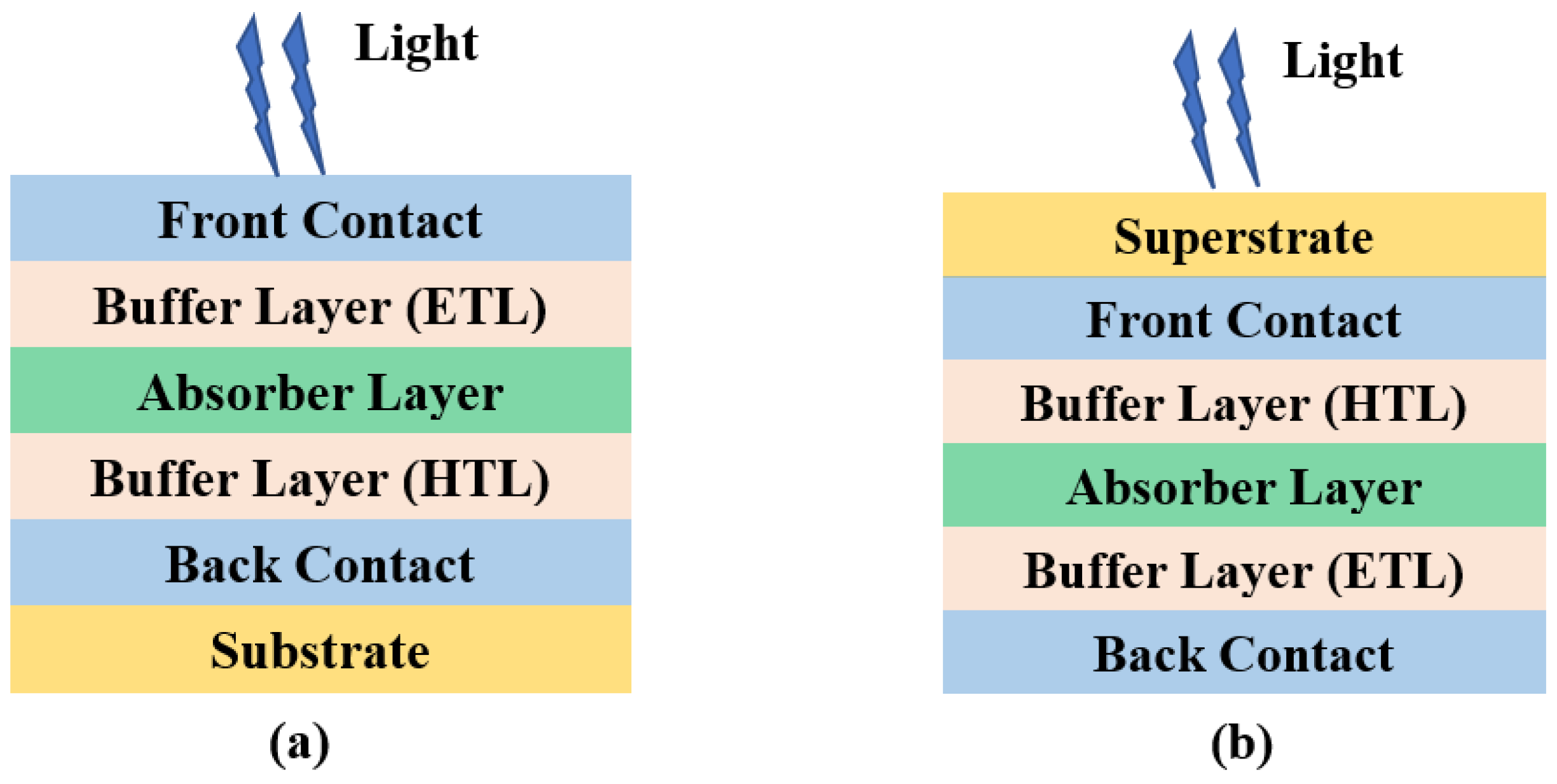
Figure 1. Schematic structure of two possible configurations of a TFSC. (a) Basic (substrate) configuration, and (b) inverted (superstrate) configuration.
Energies 16 04402 g001
Figure 2. The ABX3 perovskite crystal structure.
Energies 16 04402 g002
Figure 3. (a) The perovskite solar cell with the homojunction composed by n-type and p-type PVKs, and (b) the energy level profile (electrons (red circles) and holes (blue circles)).
Energies 16 04402 g003
Figure 6. (a) Simulated device structure for perovskite p-n homojunction solar cell, (b) J−V characteristics for various values of n-type absorber thickness, (c) J−V characteristic curves for various values of bulk defect density of n-type MAPbI3, and (d) electric field distribution inside the p-n homojunction. All represented by [108].
Energies 16 04402 g006
Figure 7. (a) J−V curves of the p-i-n cell and the p-n homojunction cell reported by He et al. utilizing NiO as an HTL [110], (b) a schematic representation of a planar PVK TFSC with p-n homojunction configuration of MAPbI3 and an inverted TFSC with ultra-thin Cu2O film as HTL reported by Maram et al. [111] (c) schematic structure of carbon-based perovskite p-n homojunction, and (d) J−V characteristics for the optimized carbon-based n-i-p perovskite and the optimized carbon-based perovskite p-n homojunctions [112].
Energies 16 04402 g007
Figure 8. (a) Schematic structures, (b) electrical performance, and (c) optical performance for four different configurations of PVK TFSCs introduced by [113], and (d) schematic structure of TCO/WS2/MAPbI3(n)/MAPbI3(p)/MoO3/Metal of graded MAPbI3(n) PVK TFSCs reported in [115].
Energies 16 04402 g008
Figure 9. (a) A schematic representation of hetero-homojunction-based structure introduced by Salem M.S. et al. [129], (b) JV curves and (c) quantum efficiency of different cases of homojunction-based lead-free TFSC [125].
Energies 16 04402 g009
Figure 10. (a) Schematic diagram of the preparation process of the Sb2Se3 quasi-homojunction TFSC, and (b) JV curve for the Sb2Se3 quasi-homojunction TFSC. Reproduced from [130].
Energies 16 04402 g010
Figure 11. (a) A schematic representation of the proposed hybrid homojunction-based configuration represented by [129], and (b) illuminated J−V characteristics for various cases of designed structures represented by [1], (c) J−V characteristics and (d) external quantum efficiency for perovskite top sub-cell, SnS bottom sub-cell, and PVK/SnS tandem.
Energies 16 04402 g011
Table 1. List of different layers in a heterojunction TFSC along with their specific roles and essential requirements.
Layer TypeRoleRequirements
Substrate/SuperstrateMechanical and thermal stabilityTransparency (superstrate)
Front ContactElectrical contactTransparent
Buffer LayersCharge extraction, light trapping, antireflectionGood band alignment
AbsorberAbsorbing light, charge extraction,Low recombination, high mobility, low defects
Back ContactElectrical contactHigh reflection
Table 2. Experimental studies for perovskite p-n homojunctions along with their structure, method of fabrication, and performance parameters.
StudyStructureMethodVOC (V)JSC (mA/cm2)FF (%)PCE (%)Year
[85]ConventionalVacuum Deposition1.09516.879.714.72018
[96]Conventional (MAPbI)Combined Deposition1.1323.8677.520.82019
Conventional (FAMAPbI)1.1224.2380.521.88
CTL-free---------8.08
[97]Conventional (MAPbI)Two-solution Deposition1.0018.6738.427.172019
Conventional (MAPbI+0.04NaI)0.9912.1849.325.94
Conventional (MAPbI+0.04KI)1.0116.5845.587.63
Conventional (MAPbI+0.04RbI)1.0218.7835.836.85
[98]ConventionalSpin-coating------------2020
[99]Conventional, Graded Pb/SnSimple three-step dynamic spin-coating1.1425.972.621.42020
ETL-free, Graded Pb/Sn1.1125.366.118.7
HTL-free, Graded Pb/Sn1.0322.747.411.1
CTL-free, Graded Pb/Sn0.8923.64910.3
[100]ConventionalTwo-step spin-coating1.13624.2879.7222020
[101]Conventional 1.25------13.22021
[102]ConventionalSpin-coating1.25117.120.7415.292021
Table 3. Modeling and simulation studies for perovskite p-n homojunctions along with their performance parameters.
StudyDevice StructureVOC (V)JSC (mA/cm2)FF (%)PCE (%)Year
[108]Au/Spiro-OMeTAD/p-MAPbI/n-MAPbI/TiO2/FTO1.1425.8577.9423.522021
[96]FTO/TiO2/n-type/p-type/Spiro-OMeTAD/Au1.14223.4373.919.792019
[109][Basic] Au/Spiro-OMeTAD/p-MAPbI/n-MAPbI/TiO2/FTO1.1120.6479.0618.192021
[Optimized]---------27.1
[110]Al/ZnO/n-MAPbI/p-MAPbI/NiO/ITO1.1118.68586.3317.92021
[Optimized]1.09320.18586.5619.1
[111]Ag/PC61BM/n-MAPbI/p-MAPbI/CuAlO2/ITO1.16119.2473.8716.482021
[112]FTO/TiO2/n-MAPbI/p-MAPbI/Carbon1.1525.0386.8925.072020
[113]CTL-free homojunction1.1924.7489.526.352022
[114]CTL-free homojunction0.801224.9378.115.62022
[115]TCO/WS2/MAPbI3(n)/MAPbI3(p)/MoO3/Metal1.1526.5587.9426.812021
TCO/WS2/(Graded)MAPbI3(n)/MAPbI3(p)/MoO3/Metal1.16427.60687.8928.26
[129]HTL-free (lead-free)0.94826.4877.219.372021
Table 4. List of some experimental and theoretical studies for new candidates p-n homojunctions.
StudyMaterialMethodVOC (mV)JSC (mA/cm2)FF (%)PCE (%)Year
[131]SnSSputtering deposition3607.5531.42021
[130]Sb2Se3Magentron sputtering combined with post-selenization treatment28022.4534.512.172021
[10]Sb2Se3Magentron sputtering29420412.412020
[132]SnSSimulation (Standalone)41026.7569.457.622022
Simulation (Optimized standalone)800~338523.3
[1]Sb2Se3Simulation (Hybrid homojunction with CdS as ETL)64332.1759.0612.232022
Simulation (Hybrid homojunction with ZnOS as ETL)70733.2970.1316.51
Simulation (Homojunction with No ETL)67127.6167.8712.58
Table 5. Summary of the PVK TFSCs challenges.
ChallengeReasonSuggested Solution
Loss of uniformity for large-sized solar cell fabricationDeposition techniques are not efficientInvestigating substitution methods for depositing PVK TFSC layers
PVK layers have high defect densityHigh doping concentrationsDiscovering more proper PVK self-doping and extrinsic doping approaches
Severe interfacial recombinationRemoval of the ETL and HTL, and
direct contact between electrode and PVK layer.
Optimize the device with interfacial engineering and defect passivation
PVK solar cells short operational lifetime under environmental conditions- Defects on crystal structure
- Reactivity between adjacent layers
- Sensitivity to moisture, oxygen, ultraviolet radiation
- High temperatures
Material engineering, novel device structure design,
electrode materials,
encapsulation method
Disclaimer/Publisher’s Note: The statements, opinions and data contained in all publications are solely those of the individual author(s) and contributor(s) and not of MDPI and/or the editor(s). MDPI and/or the editor(s) disclaim responsibility for any injury to people or property resulting from any ideas, methods, instructions or products referred to in the content.