Abstract
The aim of this study was to carry out the investigation and analysis of two-stage magnetic precession gear dynamics and the determination of the resonance frequencies, which can be a cause of the powertrain system failures. Graphical interpretation of the two-stage precession gear is presented, and two equations of the dynamics of the movable elements of the presented gearbox were determined. On the basis of these equations, the stiffness coefficients and resonance frequencies of the presented gearbox were mathematically derived. The next step was to develop a numerical model of the magnetic precession gear dynamics in the environment of MATLAB Simulink. The elaborated model allowed us to analyze the influence of varying the input speed and the load torque on the operation of the magnetic precession gear. The performed analyses of the dynamics of the magnetic precession gear showed the occurrence of a resonance phenomenon under the influence of load torque ripples with a frequency close to the natural frequency of the studied system.
1. Introduction
Modern technology, in responding to the needs of industry, provides increasingly efficient solutions to the field of mechanical energy processing. Gear transmissions are one of the key components responsible for mechanical energy processing. These components are used to transmit and adapt the rotational speed and mechanical torque between drive systems and load [1,2].
Nowadays, one of the most commonly applied solutions are mechanical gears, in which the power is transmitted by meshing the gear teeth. Mechanical gears offer high torque density and efficiency, and are easy to manufacture. However, their severe disadvantages are rapid wear due to friction between teeth, as well as high noise and vibration levels [2,3,4,5].
As a consequence the wear of the gears results in decreasing the overall reliability of the drive system and increasing the maintenance costs [1]. To overcome the deterioration of drive systems’ reliability, research has been carried out on the development of mechanical gear designs that are optimized in terms of reliability and fault tolerance [6,7]. On the other hand, to mitigate problems related to wear and the high development costs of mechanical gears, magnetic gears have become a point of interest for many researchers [8,9].
The development of research on electromagnetic phenomena in the 19th and 20th century led to the invention of the first magnetic gear (MG) [10]. Further, rapid development of MGs has become possible, mainly due to the invention of high-magnetic-energy and high-density magnets, based on rare-earth components, in the 1980s [11,12]. Compared to ferrite and Alnico magnets, rare-earth component-based magnets such as neodymium iron boron are able to provide a high residual flux density as a well as higher coercivity [13]. Progress in the development of the MGs is also linked to advances in analytical and numerical methods and tools for the analysis and design of complex magnetic circuits. In the field of magnetic gear design and analysis, magnetic equivalent circuit models (MECs) [14], current sheet models (CSMs) [15,16,17] and finite element method (FEM)-based models [18] are applied. Magnetic gears offer many advantages over their mechanical counterparts. Thanks to contactless torque transmission, magnetic gears allow us to eliminate the teeth wear problem, as well as reducing vibrations and noise, resulting in a decrease in maintenance costs and an increase in durability [19,20,21]. Natural protection against overload due to a lack of physical contact between movable elements is another very important advantage of MGs. In such gears, if the torque applied on the driven shaft increases, the internal load angle [22,23] also increases. Above a critical value of load torque, the load angle exceeds the characteristics of the stable point torque angle (typically about 90 electrical degrees), which causes the gear to fall out of sync. As a consequence, the output of the gear is decoupled from its input. In this way, severe mechanical damage can be avoided. Despite the many positive aspects of magnetic gears’ operation, they also suffer from several disadvantages. Due to the limited operation of the magnetic circuit and magnetic flux density, they cannot compete with mechanical gears in terms of torque density. Another drawback of MGs, resulting directly from contactless torque transmission through the magnetic field, is that they have very low stiffness compared to mechanical gears. This low stiffness of magnetic gears can lead to vibrations rooted in the magneto-mechanical resonance phenomenon that occurs in MGs [24,25,26,27,28]. The occurrence of magneto-mechanical resonances in a particular MG design can cause powertrain system failures. Therefore, knowledge about the natural frequencies of these magneto-mechanical resonances is very crucial at the design stage of MGs. Therefore, an effective model of the dynamic of the MG must be developed, the knowledge of which is very important in the context of implementing a given gearbox design. The paper discusses a dynamic model of a two-stage magnetic precession gear that was presented by the authors of the article in [29,30,31,32], which provides the possibility of obtaining a significantly higher ratio compared to currently known MGs solutions.
Studies on dynamics of MGs have been discussed, among others, in [24,25,26], with a focus on coaxial MGs (CMG), in most cases assuming the sinusoidal relationship between torque and the load angle. The approach presented in this paper takes into account the relationship of torque to load angle to a greater extent, determining those characteristics using a 3D FEM model of the MPG. It is also worth mentioning that the geometry of an MPG is significantly different from that of a CMG.
The paper is organized as follows. In Section 2, the concept, description of the design, and basic kinematics are presented. A description of the model of gear dynamics and the determination of the stiffness coefficients as well as resonance frequencies are given in Section 3. Next, the numerical model of the gearbox dynamics developed in MATLAB Simulink R2022b is described in Section 4. In Section 5, the results of the investigations are presented and discussed. Finally, the conclusions resulting therefrom are presented in Section 6.
2. Design and 3D FEM Model of a Two-Stage Magnetic Precession Gear
The two-stage magnetic precession gear (MPG) consists of four primary components: the input shaft (a), the immovable ring (b), the intermediate ring (c), and the output ring with the output shaft (d). Permanent magnets are fixed to the circumferences of each ring. The kinematic scheme of the discussed MPG is illustrated in Figure 1.
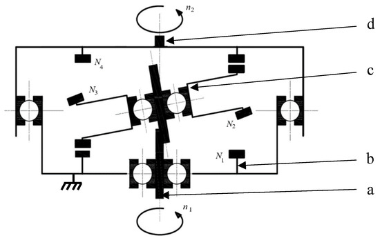
Figure 1.
Kinematic scheme of the MPG [29]: n1—input rotational speed, n2—output rotational speed Ni—the number of neodymium magnets on the i-th ring.
The speed of the output shaft depends on the number of magnets on each ring, and can be determined using the following formula [32]:
In the steady state (under constant load), the gear ratio is constant. However, due to the low stiffness of magnetic gears compared to toothed gears (the relationship between magnetic torque and load angle is close to sinusoidal) in transient states, the instantaneous value of the gear ratio changes.
A detailed description of the gearbox concept and an extended kinematic analysis are presented and discussed in [31].
As discussed in the introduction section, the inherent feature of magnetic gears is noticeably lower stiffness compared to mechanical gears [33]. As the torque changes, the mechanical angle between movable elements also changes, as shown in Figure 2. This dependence is analogous to the relationship between the load torque and the internal load angle in synchronous motors [22,23]. The blue arrows in Figure 2 indicate the direction and value of the load torque.

Figure 2.
Illustration of the load angle changes upon the load torque.
There are two load angles defined for the studied system. The load angle between the immovable ring and the intermediate ring will be marked as β1, and the load angle between the intermediate ring and the output ring will be depicted as β2.
Electrical load angles can be calculated using the following formulas:
where β1m is the mechanical angle between the immovable ring and the intermediate ring, and β2m is the mechanical angle between the intermediate ring and the output ring.
The developed 3D FEM model of the magnetic field in the proposed MPG allowed us to determine the dependencies of the magnetic torques Tm1 and Tm2 on the load angles β1 and β2, presented in Figure 3. A detailed description of these studies as well as their experimental verification is included in [30,31,32].
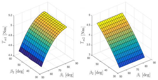
Figure 3.
Torques Tm1 and Tm2 as a function of the internal load angles β1 and β2 [30].
3. Model of the MPG Dynamics
Based on the description of the gearbox presented in Section 2, a mathematical model of the dynamics of the MPG is proposed. The analysis of such a complex system, in which the intermediate ring moves with a precession motion (which is a combination of rotations about two inclined axes), is very challenging. On the other hand, the inertia and speed of this precession motion is negligible compared to the rotational motion about the main (shaft) axis. Therefore, in the proposed model of the MPG, only the dynamics around the main axis of rotation of the MPG’s movable elements are analyzed. To help understand the proposed mathematical model, it is advantageous to illustrate the MPG operation as a two-stage gear, with ‘magnetic springs’ representing the relationship of torque and internal load angle discussed in the previous section. A graphical interpretation of this description of the MPG’s operation is shown in Figure 4.

Figure 4.
Graphical interpretation of a two-stage precession gearbox.
To formulate a mathematical model, it is necessary to determine two equations of the dynamic of the movable elements of the presented gearbox. Equation (4) describes the dynamic of the intermediate ring, and Equation (5) describes the dynamic of the output ring. Equations (4) and (5) consist of the mechanical quantities, i.e., the moments of inertia of the intermediate ring J2 and the output ring J3, the load torque (Tload), as well as the coefficients kf2 and kf3, representing the mechanical friction and losses in the magnetic circuit caused by eddy currents, and magnetic hysteresis phenomena dependent on the angular velocities of each rings (ω2, ω3). It is assumed that these ‘magnetic’ losses depend directly on the velocity in the changes of the magnetic field. Equations (4) and (5) are coupled by the magnetic torques resulting from interactions between the magnetic field in the air gaps excited by the magnets (with Tm1 being those between the immovable and intermediate rings, and Tm2 being those between the intermediate and output rings).
The torques Tm1 and Tm2 have magnetic origins that depend on the internal load angles β1 and β2. According to their previously discussed relationship to synchronous machines, the torque vs. angle characteristics is close to the sinus function. The equations of the MPG dynamic must incorporate the dependencies of the internal load angles on the load torque. To keep the proposed equations mathematically correct, the internal load angles β are replaced by equivalent forms of the angle’s dependence α. Assuming they have sinusoidal torque vs. angle characteristics, Equations (4) and (5) will take the following form:
where is the gear ratio at the first stage, is the gear ratio at the second stage, and is the number of pole pairs on each ring.
The angle of rotation of the intermediate ring (α2) depends on the number of magnets on each ring, as well as on the precession angle γ:
where is the precession angle.
To accurately determine the dynamic properties of the MPG, it is necessary to calculate the stiffness coefficients. Those coefficients define the capability of the gearbox in terms of stable load-dependent operation. An additional parameter related to the stiffness coefficient and the phenomena in the magnetic gearbox is the resonance frequency, which represents the harmonic oscillations of the gearbox. Harmonic oscillations start when the system is brought out of the position of equilibrium, and a force proportional to the deflection occurs, which tries to restore this state of equilibrium. The phenomenon whereby an oscillating system with external forcing reaches its maximum amplitude is called resonance. The frequency of the external forcing at which the resonance occurs is called the resonance frequency. When there is no damping in the system, the resonance frequency is equal to the natural frequency of the system. When there is significant damping, the resonance frequency is less than the system’s natural frequency, and decreases as the drag forces increase. In the case of the studied MPG, two resonant systems can be distinguished: one for the intermediate ring (9), and a second for the output ring (10). To define the stiffness coefficients, a Taylor expansion of the load angles is used to assign the dynamics equations of the movable elements under a specific load condition corresponding to the angle β0 [24]. Given the consideration of two gear stages and different internal load angles, the β0 angle should be split into two independent β01 and β02 angles. The angular positions of the intermediate ring (α2) and output ring (α3) are expressed as a mechanical angles. The trigonometric functions in (9) and (10) must then be converted to the electrical angles.
Applying the Laplace transform to the above equations, functions describing the stiffness coefficients (Wt1, Wt2), resonance frequencies (ωt1, ωt1) and the damping factors (ξ1, ξ2) of the intermediate and output rings were obtained for given load angles (β01, β02) [24].
Simplifying the value of the stiffness coefficient by introducing linearity while considering the center of the coordinate system, it can be written in the following form:
The above mathematical considerations show the relationships and influence of the various physical phenomena occurring in the gearbox. The mathematical interpretation of the stiffness coefficients and resonance frequency takes into account the forces arising in the concerned gear stages.
4. Numerical Model of the MPG Dynamics
In order to study the performance of the proposed gearbox, the mathematical model discussed in the previous section was implemented in the environment of MATLAB Simulink.
The main transmission system is shown in Figure 5. The ratio of the analyzed gearbox is 144, and the numbers of magnets on each individual ring (as indicated in Figure 1) are the following: N1 = 22, N2 = 24, N3 = 26, N4 = 24. Each of the gear stages was modelled separately, as a subsystem of the torques and angles coupled with each other. The setpoint signals are the input rotational speed defined by the ramp function, and the output load torque defined by the signal builder block.
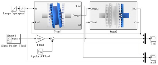
Figure 5.
Graphical interpretation of a two-stage precession gearbox.
The developed model allows us to calculate the MPG’s dynamic response, i.e., the mechanical angles, internal load angles and torques acting on the intermediate and output ring.
In formulating the mathematical model discussed in Section 3, an approximation of the torque vs. internal load angles was assumed using a sinusoidal function. In order to increase the accuracy of the developed numerical model, the characteristics of the magnetic torques were determined using a 3D FEM model of the magnetic field in the gear, as described in Section 2. The determined torque vs. internal load angle characteristics were incorporated into the numerical model of the gear dynamics using interpolation and extrapolation techniques built in the lookup table runtime and implemented in Simulink. The models of each stage are, in general, similar. The implementation of the first stage is shown in Figure 6. The input parameters for the first stage subsystem are the value of the rotational speed n1 and the magnetic torque Tm2. The dynamic torque acting on the intermediate ring is determined, taking into account the magnetic torque Tm1 and the torque drop associated with energy losses in the system, which themselves are related to friction in the bearings and eddy current losses. The model of the second stage of the gear, shown in Figure 7, is developed in a similar way, taking into account the modified input and output parameters. The inputs are the angular speed of the intermediate ring about the gearbox’s main axis of rotation, and the external load applied to the gearbox output shaft.
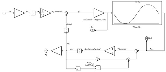
Figure 6.
Model developed in MATLAB Simulink, representing the first stage of the MPG.
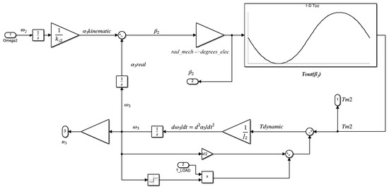
Figure 7.
Model developed in MATLAB Simulink, representing the second stage of the MPG.
The moments of inertia of the gearbox’s components were determined using a model of gear geometry developed in the professional CAD package, Autodesk Inventor.
5. Results
Studies of the gear’s dynamic operation were carried out using the model described in Section 3 and Section 4. The influence of varying the input speed and the load torque on the output shaft of the proposed MPG on the rotational speeds of the gearbox components, as well as the torques acting on the intermediate and output ring, were examined. According to the assumptions of the numerical model, the input speed n1 and the output torque Tout are the Input parameters expressed by the sources. In order to study the impact of the gear’s magneto-mechanical resonances on its performance, several cases were studied. First, the behavior of the gear was examined while linearly increasing load torque; in the studied case, the assumed value of the ramping time of the input speed was equal to 5 s, while the ramping time of the load torque was equal to 15 s. The input shaft of the gear was accelerated from 0 to 1500 rpm with constant acceleration. Simultaneously, the load torque was linearly increased from 0 to 3 Nm in a time of 15 s. After reaching the target load torque value for the next 5 s, the gear is operated at constant speed and torque conditions. Next, the response to the rapid change of the load torque from 3 to 0.6 Nm is studied. The determined responses of the model, i.e., the speeds and torques acting on the considered elements of the transmission system, is shown in Figure 8. The course of the input parameters, i.e., the input speed n1 and the load torque Tload, is marked in the figures by the blue frames.
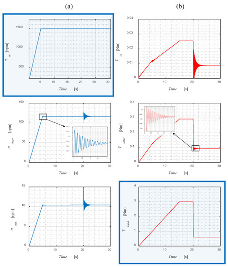
Figure 8.
Torque (a) and speed (b) waveforms for the studied gear load.
The above waveforms show a comparison of the individual gear stages, detailing the speeds (Figure 8a) and torques (Figure 8b). It is apparent that every change in input speed or load torque causes oscillations of the movable elements of the gear. The first oscillations are visible in the fifth second of the simulation when the input shaft stops accelerating. Further oscillations occur as the load torque changes, particularly after a rapid fall in the load in the 20th second of the simulation. The frequency of the observed oscillations is approximately 7 Hz.
The model also allows for investigation of the resonance phenomenon in the gearbox. In order to study resonance response, the load torque excitation was modified by adding sinusoidal ripples (see Figure 9) of constant amplitude 0.15 Nm and frequency fr to the main value. The gearbox behavior was examined in the same conditions, i.e., the course of input speed and load torque; however, the load torque of three different frequencies of torque ripples (fr = 1, 7 and 15 Hz) were studied. The obtained gear responses for the studied frequencies of the torque ripples are shown in Figure 10, Figure 11 and Figure 12, respectively. The greatest oscillations of the gear rings occurred when the frequency of the ripples coincided with the gear’s natural frequency. The quantitative assessment of the torque and speed ripples has been summarized in Table 1.
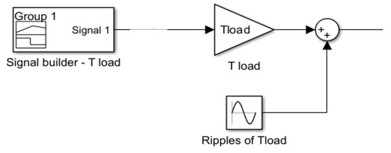
Figure 9.
Modification of the MATLAB Simulink model with the addition of load torque ripples.
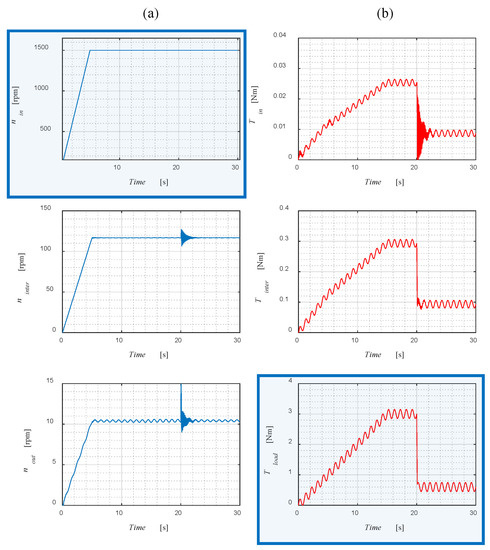
Figure 10.
Torque (a) and speed (b) waveforms for the studied gear load, with torque ripples of fr = 1 Hz.
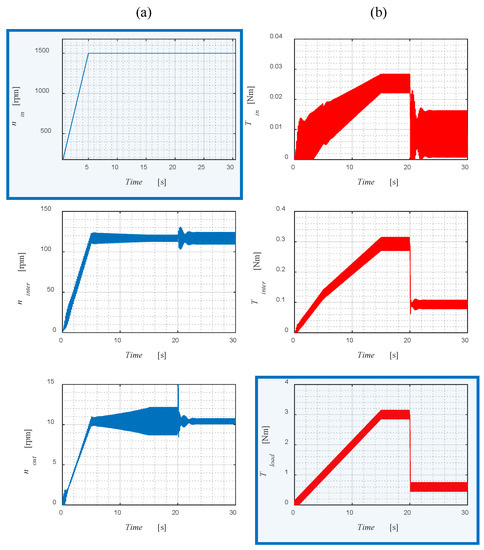
Figure 11.
Torque (a) and speed (b) waveforms for the studied gear load, with torque ripples of fr = 7 Hz.
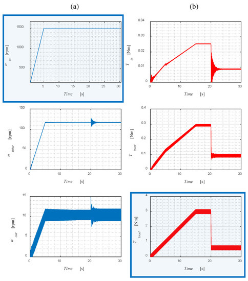
Figure 12.
Torque (a) and speed (b) waveforms for the studied gear load, with torque ripples of fr = 15 Hz.

Table 1.
Comparison of input torque and output speed ripples between 15 and 20 s of simulation for different load torque ripple frequencies.
Comparing the obtained responses, it can be observed that for the load torque of ripples with a frequency fr equal to 7 Hz, the amplitudes of the oscillations of speed and torque are the highest. However, it can also be noticed that the load ripples have no impact on the input speed. This is due to the fact that in the proposed approach, the input speed is forced; as a consequence, it is not taken into account in the analytical consideration of the resonance effects affecting the model.
6. Conclusions
The paper discusses a model for the dynamics of a magnetic precession gear. Due to the complex kinematics of the considered MPG, a simplified model of its dynamics was proposed, which takes into account only the rotational motion of components around the main axis of the gearbox. Despite the introduced simplification, the proposed model captures the nature of the magneto-mechanical resonant phenomena occurring in the studied gearbox with high fidelity. The present work may act as a prelude to further studies of the dynamics of the developed prototype precession magnetic gearbox.
Accurate knowledge of the dynamic properties of magnetic gears is of particular importance in the context of their application in drive systems. Magnetic gears are characterized by a relatively small stiffness coefficient, and are, by their nature, magneto-mechanical resonant systems. In the drive system, the occurrence of torque ripples with a frequency close to the resonant frequency of the gearbox can lead to a loss of magnetic coupling and, in extreme cases, cause the cause of destruction of the drive system. Accurate methods to determine the resonant frequencies of gearboxes will make it possible to correctly select the parameters of drive control systems, taking into account the avoidance of resonant frequencies of gearboxes, which, according to the Formulas (15) and (16), depend on the structure of the gearbox (its precession angle, ratio, and dimensions, which translate into moments of inertia) and the load of the gearbox.
Author Contributions
Conceptualization, L.M. and C.J.; Methodology, L.M.; Formal analysis, L.M. and C.J.; Investigation, L.M. and M.M.; Writing—original draft, L.M. and M.M.; Writing—review & editing, C.J.; Supervision, C.J. All authors have read and agreed to the published version of the manuscript.
Funding
This research was supported by the National Ministry of Science and Higher Education in Poland as a part of research subsidy (project nos. 0614/SBAD/1565, 0614/SBAD/1579 and 0212/SBAD/0568.
Data Availability Statement
Not applicable.
Conflicts of Interest
The authors declare no conflict of interest.
Nomenclature
| n1 | input rotational speed |
| n2 | output rotational speed |
| Ni | number of neodymium magnets on the i-th ring |
| β1m | mechanical angle between the immovable ring and the intermediate ring |
| β2m | mechanical angle between the intermediate ring and the output ring |
| β1 | load angle between the immovable ring and the intermediate ring |
| β2 | load angle between the intermediate ring and the output ring |
| Tm1 | magnetic torque resulting from interaction between the magnetic field in the air gaps excited by the magnets between immovable and intermediate rings |
| Tm1max | maximal value of magnetic torque resulting from interaction between the magnetic field in the air gaps excited by the magnets between immovable and intermediate rings |
| Tm2 | magnetic torque resulting from interaction between the magnetic field in the air gaps excited by the magnets between intermediate and output rings |
| Tm2max | maximal value of magnetic torque resulting from interaction between the magnetic field in the air gaps excited by the magnets between intermediate and output rings |
| J2 | moments of inertia of the intermediate ring |
| J3 | moments of inertia of the output ring |
| Tload | load torque |
| kf2 | coefficient representing mechanical friction and losses in the magnetic circuit caused by eddy currents and magnetic hysteresis phenomena in the intermediate ring |
| kf3 | coefficient representing mechanical friction and losses in the magnetic circuit caused by eddy currents and magnetic hysteresis phenomena in the output ring |
| ki1 | gear ratio at the first stage |
| ki2 | gear ratio at the second stage |
| pi | number of pole pairs on each ring |
| γ | precession angle |
| β0 | angle corresponding to the specific load condition |
| β01 | angle corresponding to the specific load condition for the intermediate ring |
| β02 | angle corresponding to the specific load condition for the output ring |
| α2 | angular position of the intermediate ring |
| α3 | angular position of the output ring |
| Wt1 | function describing the stiffness coefficients of the intermediate ring |
| Wt1_0 | stiffness coefficient of the intermediate ring simplified by introducing linearity with consideration of the center of the coordinate system |
| Wt2 | functions describing the stiffness coefficients of the output ring |
| Wt2_0 | stiffness coefficient of the output ring simplified by introducing linearity with consideration of the center of the coordinate system |
| ξ1 | damping factor for the intermediate ring |
| ξ2 | damping factor for the output ring |
| ωt1 | resonance frequency for the intermediate ring |
| ωt2 | resonance frequency for the output ring |
| ω2 | angular velocity of the intermediate ring |
| ω3 | angular velocity of the output ring |
| fr | frequency of load torque ripples |
References
- Sun, K.; Wang, G.; Lu, Y. Optimization Method of Bevel Gear Reliability Based on Genetic Algorithm and Discrete Element. Eksploat. Niezawodn. Maint. Reliab. 2019, 21, 186–196. [Google Scholar] [CrossRef]
- He, Z.; Zhang, T.; Lin, T. Novel Mathematical Modelling Method for Meshing Impact of Helical Gear. Mech. Mach. Theory 2020, 152, 103949. [Google Scholar] [CrossRef]
- Karabacak, Y.E.; Özmen, N.G.; Gümüşel, L. Worm Gear Condition Monitoring and Fault Detection from Thermal Images via Deep Learning Method. Eksploat. Niezawodn. Maint. Reliab. 2020, 22, 544–556. [Google Scholar] [CrossRef]
- Ramadani, R.; Belsak, A.; Kegl, M.; Predan, J.; Pehan, S. Topology Optimization Based Design of Lightweight and Low Vibration Gear Bodies. Int. J. Simul. Model. 2018, 17, 92–104. [Google Scholar] [CrossRef] [PubMed]
- Yuan, B.; Chang, L.; Liu, G.; Chang, S.; Liu, L.; Shen, Y. An Efficient Three-Dimensional Dynamic Contact Model for Cylindrical Gear Pairs with Distributed Tooth Flank Errors. Mech. Mach. Theory 2020, 152, 103930. [Google Scholar] [CrossRef]
- Stetter, R.; Göser, R.; Gresser, S.; Till, M.; Witczak, M. Fault-Tolerant Design for Increasing the Reliability of an Autonomous Driving Gear Shifting System. Eksploat. Niezawodn. Maint. Reliab. 2020, 22, 482–492. [Google Scholar] [CrossRef]
- Yuan, W.; Wang, H.; Guo, Q.; Wang, W.; Zhu, Y.; Yu, J.; Yang, X. Study on Wear Mechanism of Helical Gear by Three-Body Abrasive Based on Impact Load. Materials 2022, 15, 4135. [Google Scholar] [CrossRef]
- Miladinović, S.; Ivanovic, L.; Blagojevic, M.; Stojanovic, B. The development of magnetic gears for transportation applications. Mobil. Veh. Mech. 2017, 43, 41–55. [Google Scholar] [CrossRef]
- Tlali, P.M.; Wang, R.; Gerber, S. Magnetic Gear Technologies: A Review. In Proceedings of the 2014 International Conference on Electrical Machines (ICEM), Berlin, Germany, 2–5 September 2014; pp. 544–550. [Google Scholar]
- Armstrong, C.G. Power-Transmitting Device. US Patent 687292A, 26 November 1901. [Google Scholar]
- Li, X.; Chau, K.-T.; Cheng, M.; Hua, W. Comparison of Magnetic-Geared Permanent-Magnet Machines. Prog. Electromagn. Res. 2013, 133, 177–198. [Google Scholar] [CrossRef]
- Tsurumoto, K.; Kikuchi, S. A New Magnetic Gear Using Permanent Magnet. IEEE Trans. Magn. 1987, 23, 3622–3624. [Google Scholar] [CrossRef]
- Park, E.-J.; Jung, S.-Y.; Kim, Y.-J. Comparison of Magnetic Gear Characteristics Using Different Permanent Magnet Materials. IEEE Trans. Appl. Supercond. 2020, 30, 5200704. [Google Scholar] [CrossRef]
- Derbas, H.; Williams, J.; Koenig, A.; Pekarek, S. A Comparison of Nodal- and Mesh-Based Magnetic Equivalent Circuit Models. Energy Convers. IEEE Trans. 2009, 24, 388–396. [Google Scholar] [CrossRef]
- Boules, N. Two-Dimensional Field Analysis of Cylindrical Machines with Permanent Magnet Excitation. IEEE Trans. Ind. Appl. 1984, IA-20, 1267–1277. [Google Scholar] [CrossRef]
- Furlani, E. Analytical Analysis of Magnetically Coupled Multipole Cylinders. J. Phys. D Appl. Phys. 1999, 33, 28. [Google Scholar] [CrossRef]
- Wu, Y.-C.; Wang, C.-W. Transmitted Torque Analysis of a Magnetic Gear Mechanism with Rectangular Magnets. Appl. Math. Inf. Sci. 2015, 9, 1059–1065. [Google Scholar] [CrossRef]
- Wu, Y.-C.; Jian, B.-S. Magnetic Field Analysis of a Coaxial Magnetic Gear Mechanism by Two-Dimensional Equivalent Magnetic Circuit Network Method and Finite-Element Method. Appl. Math. Model. 2015, 39, 5746–5758. [Google Scholar] [CrossRef]
- Kołodziej, J.; Kowol, M.; Mynarek, P.; Gabor, R.; Łukaniszyn, M. Forces in Axial Flux Magnetic Gears with Integer and Fractional Gear Ratios. Energies 2021, 14, 855. [Google Scholar] [CrossRef]
- Wang, Y.; Filippini, M.; Bianchi, N.; Alotto, P. A Review on Magnetic Gears: Topologies, Computational Models, and Design Aspects. IEEE Trans. Ind. Applicat. 2019, 55, 4557–4566. [Google Scholar] [CrossRef]
- Ruiz-Ponce, G.; Arjona, M.A.; Hernandez, C.; Escarela-Perez, R. Design Optimization of an Axial Flux Magnetic Gear by Using Reluctance Network Modeling and Genetic Algorithm. Energies 2023, 16, 1852. [Google Scholar] [CrossRef]
- Ionel, D.M.; Eastham, J.F.; Miller, T.J.E.; Demeter, E. Design Considerations for Permanent Magnet Synchronous Motors for Flux Weakening Applications. IEE Proc. Electr. Power Appl. 1998, 145, 435–440. [Google Scholar] [CrossRef]
- Stumberger, B.; Stumberger, G.; Hadziselimovic, M.; Marcic, T.; Virtic, P.; Trlep, M.; Gorican, V. Design and Finite-Element Analysis of Interior Permanent Magnet Synchronous Motor With Flux Barriers. IEEE Trans. Magn. 2008, 44, 4389–4392. [Google Scholar] [CrossRef]
- Desvaux, M.; Latimier, R.L.G.; Multon, B.; Sire, S.; Ahmed, H.B. Analysis of the Dynamic Behaviour of Magnetic Gear with Nonlinear Modelling for Large Wind Turbines. In Proceedings of the 2016 XXII International Conference on Electrical Machines (ICEM), Lausanne, Switzerland, 4–7 September 2016; pp. 1332–1338. [Google Scholar]
- Hartung, S.; Rehberg, I. Dynamics of a Magnetic Gear with Two Cogging-Free Operation Modes. Arch. Appl. Mech. 2021, 91, 1423–1435. [Google Scholar] [CrossRef]
- Kołodziej, J. Analiza własności dynamicznych współosiowej przekładni magnetycznej. Electrotech. Rev. 2019, 1, 248–251. [Google Scholar] [CrossRef]
- Montague, R.; Bingham, C.; Atallah, K. Servo Control of Magnetic Gears. IEEE/ASME Trans. Mechatron. 2012, 17, 269–278. [Google Scholar] [CrossRef]
- Vournas, D. Modeling and Control of Magnetic Gear Dynamics in a Wind Turbine Drivetrain. Ph.D. Thesis, Portland State University, Portland, OR, USA, 2000. [Google Scholar]
- Macyszyn, Ł.; Staniek, R.; Myszkowski, A. Przekładnia Magnetyczna Precesyjna. PL Patent 229502, 2 March 2018. [Google Scholar]
- Macyszyn, L.; Jedryczka, C.; Myszkowski, A. Simulation and Experimental Investigation of a Two-Stage Magnetic Precession Gear. Energies 2021, 14, 1838. [Google Scholar] [CrossRef]
- Macyszyn, Ł.; Jedryczka, C.; Staniek, R. Design and Finite Element Analysis of Novel Two-Stage Magnetic Precession Gear. Int. J. Simul. Model. 2019, 18, 586–595. [Google Scholar] [CrossRef]
- Macyszyn, Ł.; Myszkowski, A.; Staniek, R.; Pabiszczak, S. Two-Stage Precession Type Gear: Design, Geometric and Kinematic Analysis. In Proceedings of the American Society of Mechanical Engineers Digital Collection, Tampa, FL, USA, 3–9 November 2017. [Google Scholar]
- Coulomb, J. A Methodology for the Determination of Global Electromechanical Quantities from a Finite Element Analysis and Its Application to the Evaluation of Magnetic Forces, Torques and Stiffness. IEEE Trans. Magn. 1983, 19, 2514–2519. [Google Scholar] [CrossRef]
Disclaimer/Publisher’s Note: The statements, opinions and data contained in all publications are solely those of the individual author(s) and contributor(s) and not of MDPI and/or the editor(s). MDPI and/or the editor(s) disclaim responsibility for any injury to people or property resulting from any ideas, methods, instructions or products referred to in the content. |
© 2023 by the authors. Licensee MDPI, Basel, Switzerland. This article is an open access article distributed under the terms and conditions of the Creative Commons Attribution (CC BY) license (https://creativecommons.org/licenses/by/4.0/).