
Review of Coupling Methods of Compressed Air Energy Storage Systems and Renewable Energy Resources
 ,
,
Abstract
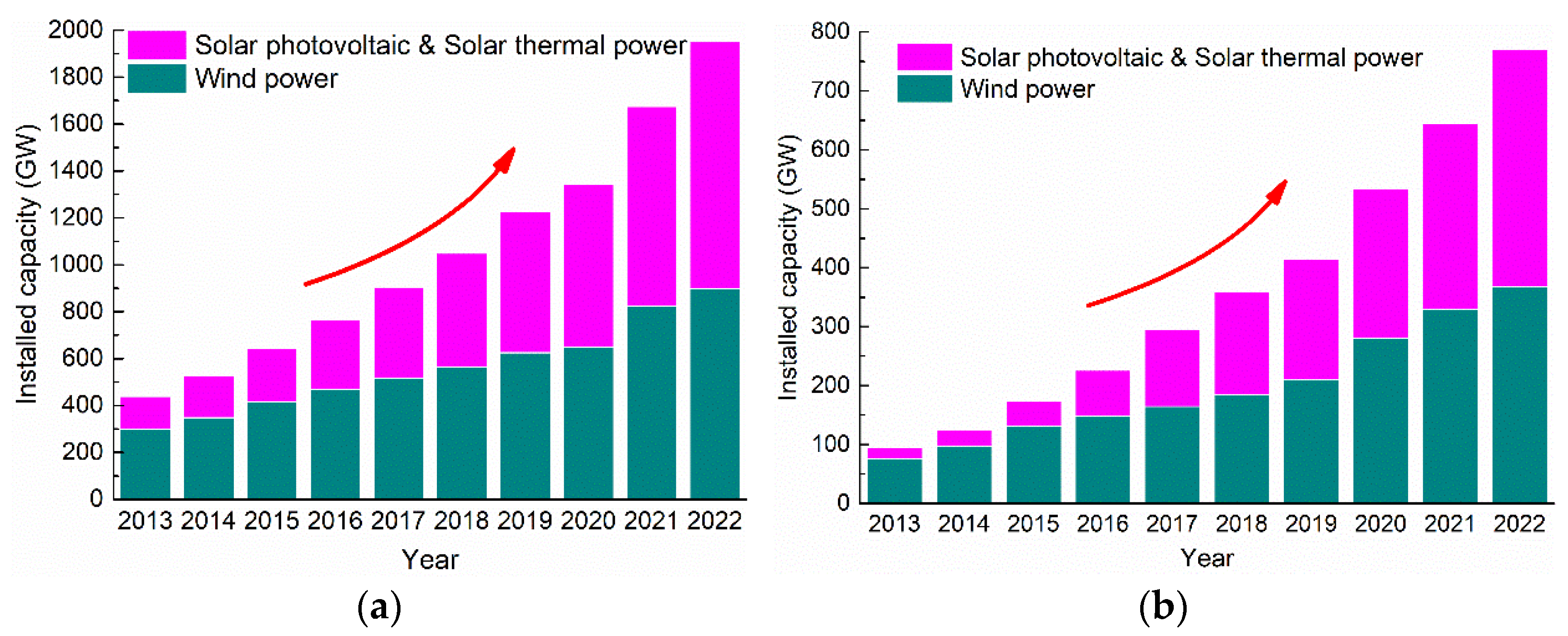
:1. Introduction
2. CAES Systems Coupled with Wind Energy
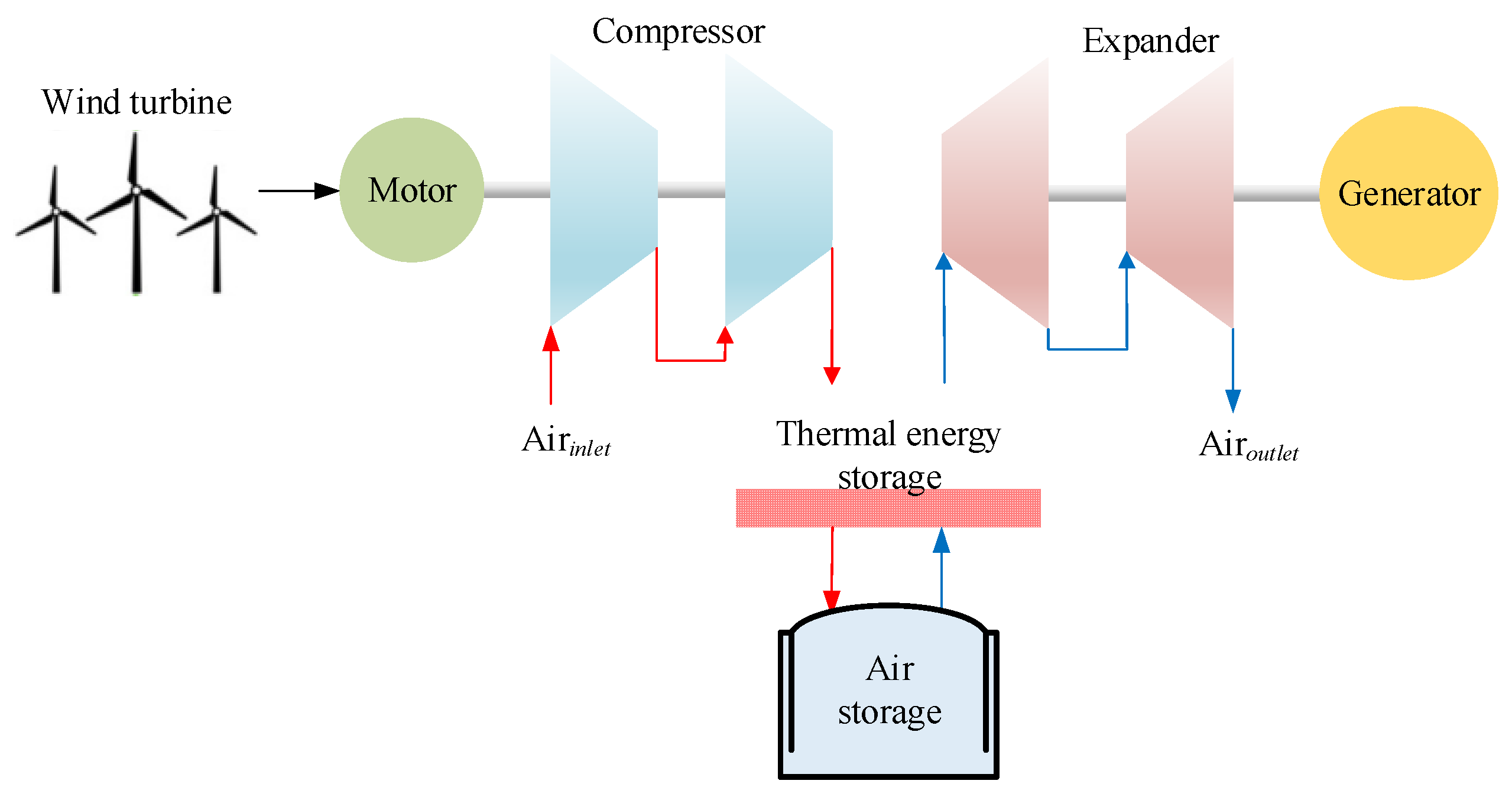
2.1. Wind Power Connecting to CAES in Series
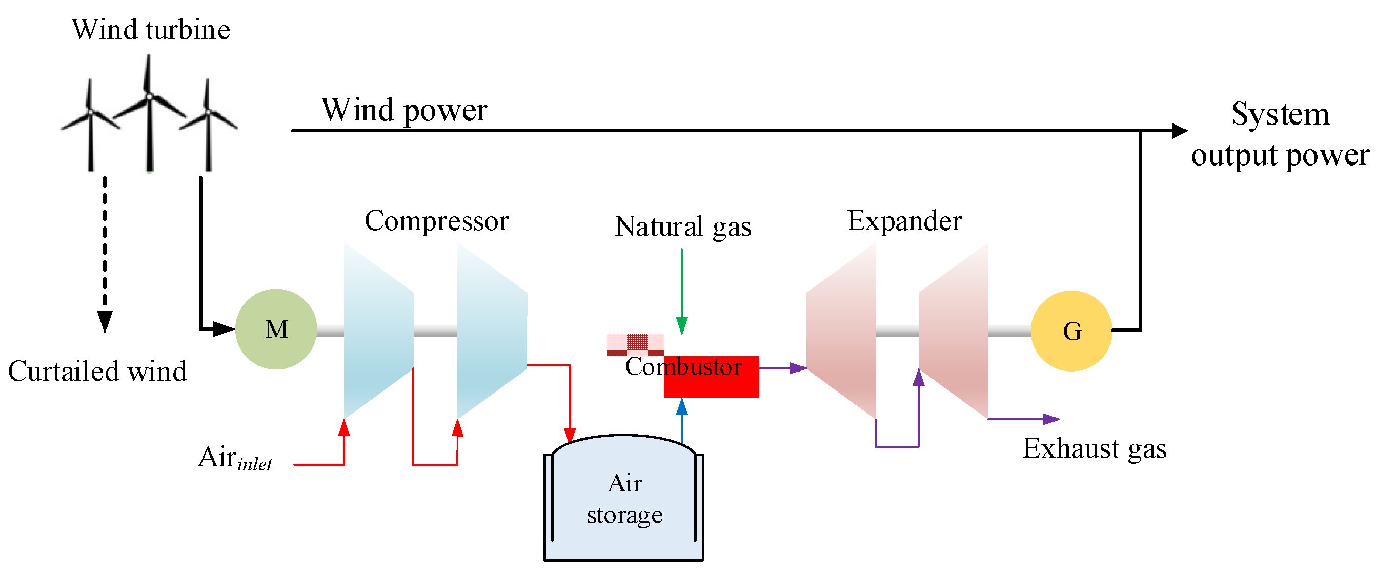
2.2. Wind Power Connecting to CAES in Parallel
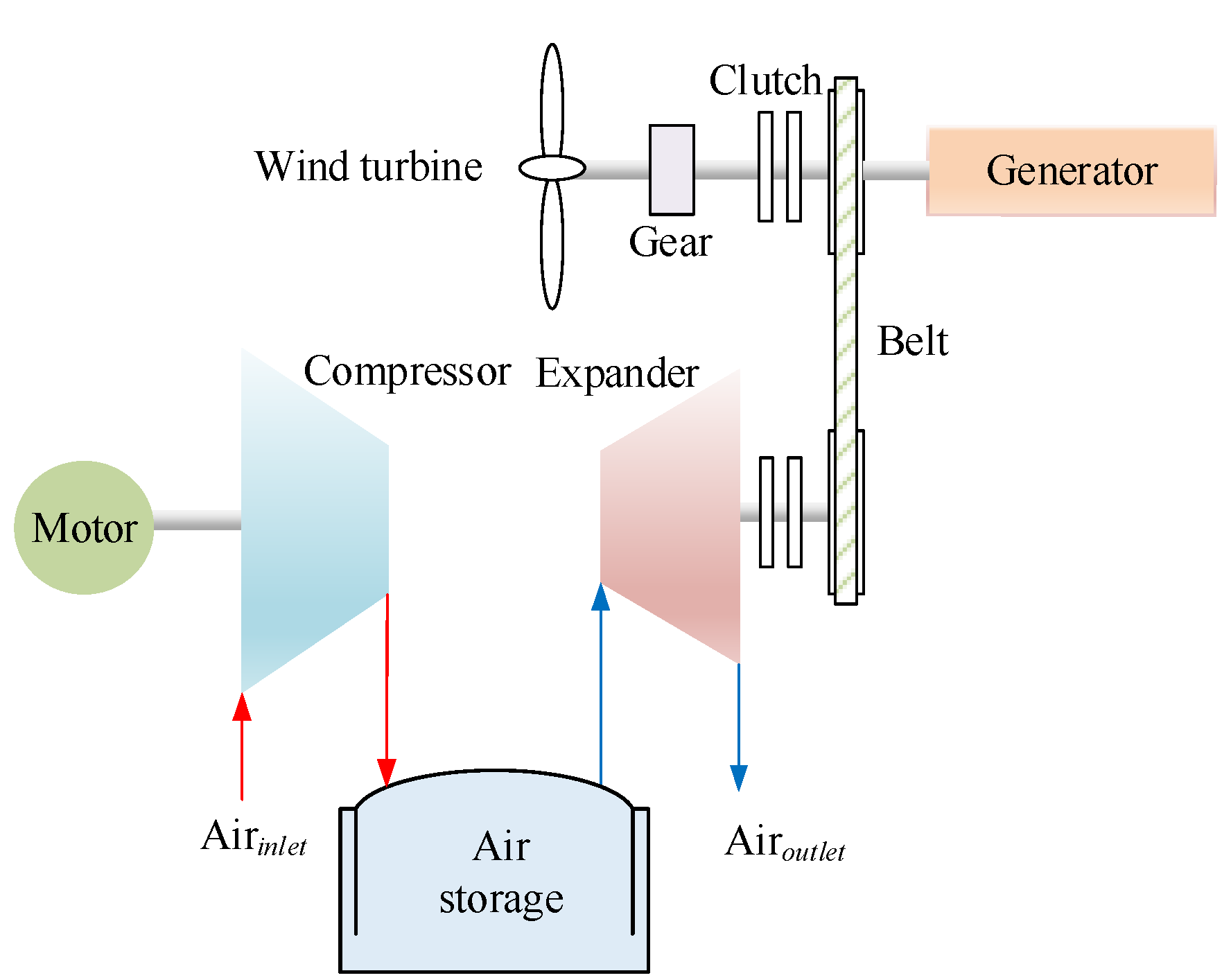
2.3. Wind Power Connecting to CAES in Series and in Parallel
2.4. Wind Power and Wind Heat Connecting to CAES
2.5. Other Coupling Types
3. CAES Systems Coupled with Solar Energy
3.1. Solar-Assist CAES by Combining the Heating Sources at Expander Inlet
- ➢
- Regenerator, solar energy, and combustion chamber combined heating
- ➢
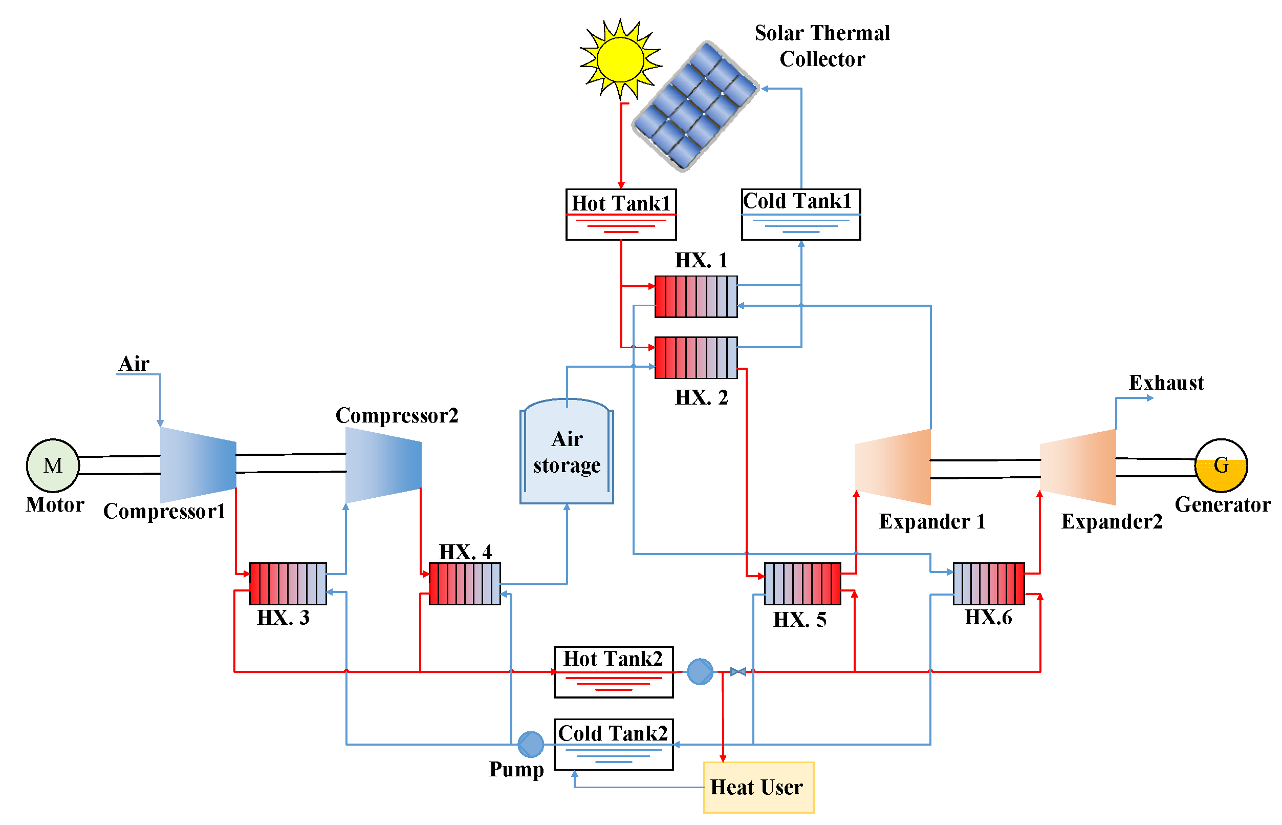
- Compression heat and solar combined heating
- ➢
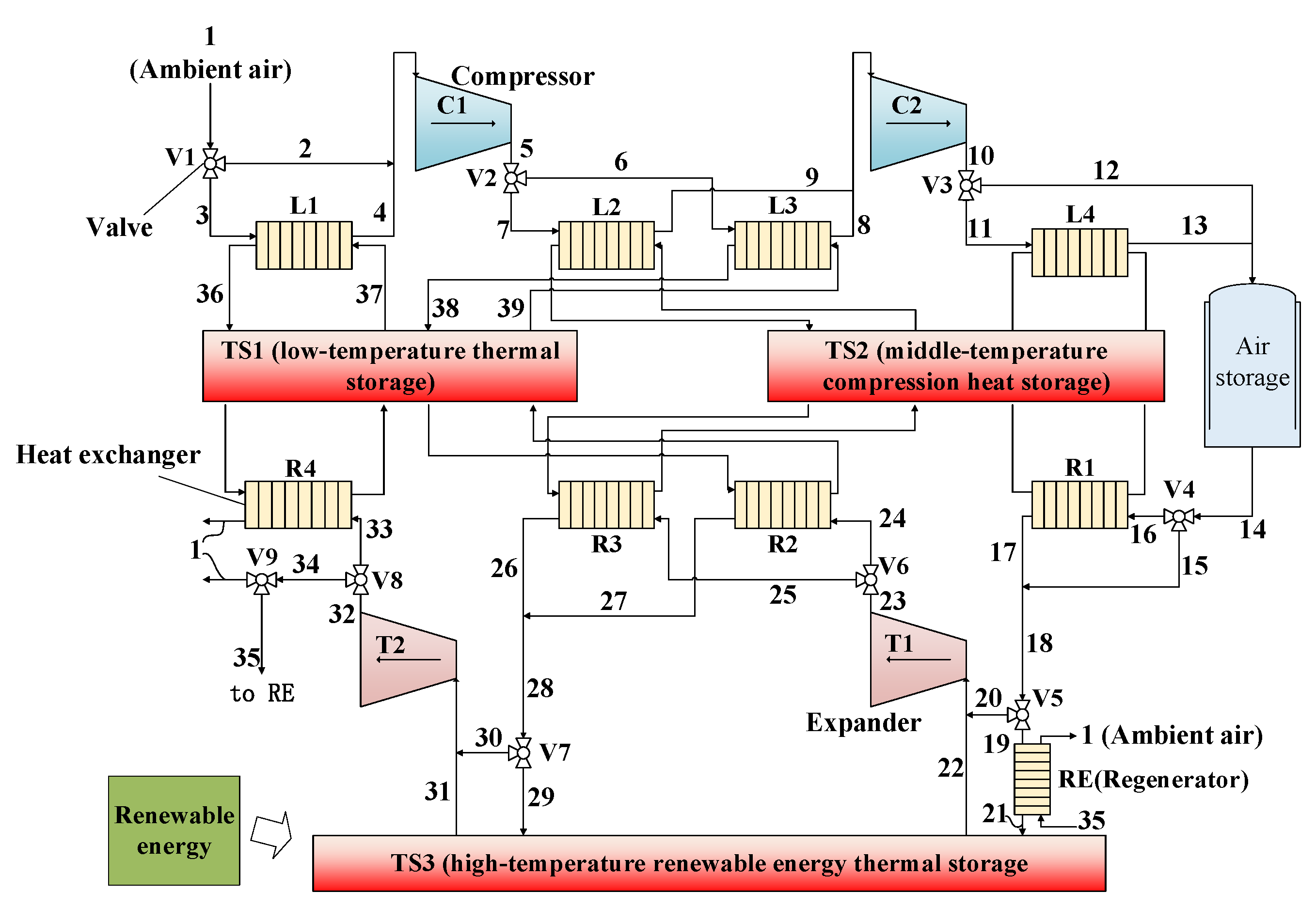
- Regenerator and solar combined heating
3.2. Solar-Assist CAES with Bottom Cycle
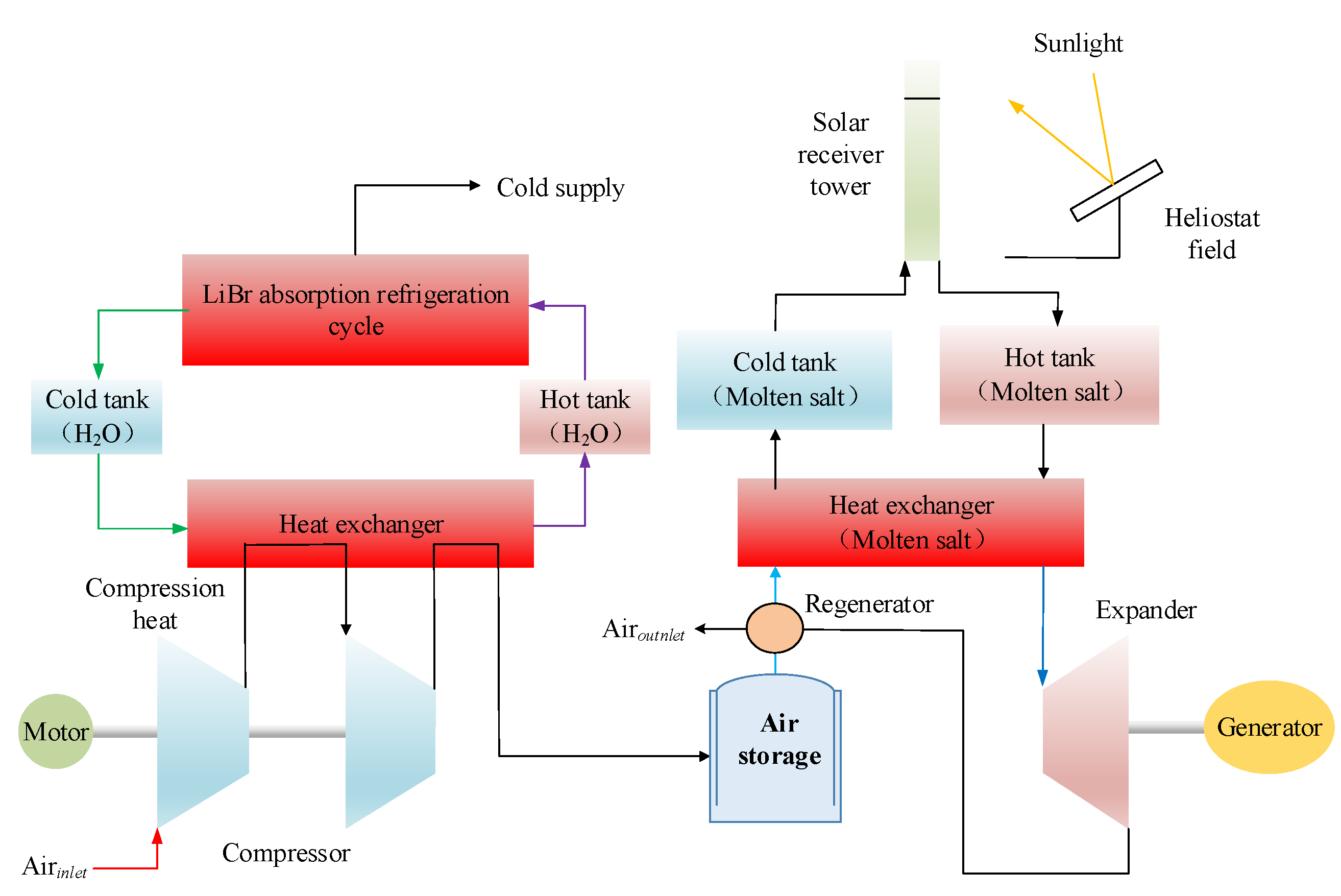
3.3. Solar-Assist CAES with CCHP or Producing Other Products
4. CAES Systems Coupled with Both Solar Energy and Wind Energy
5. CAES Systems Coupled with Biomass Energy
- (1)
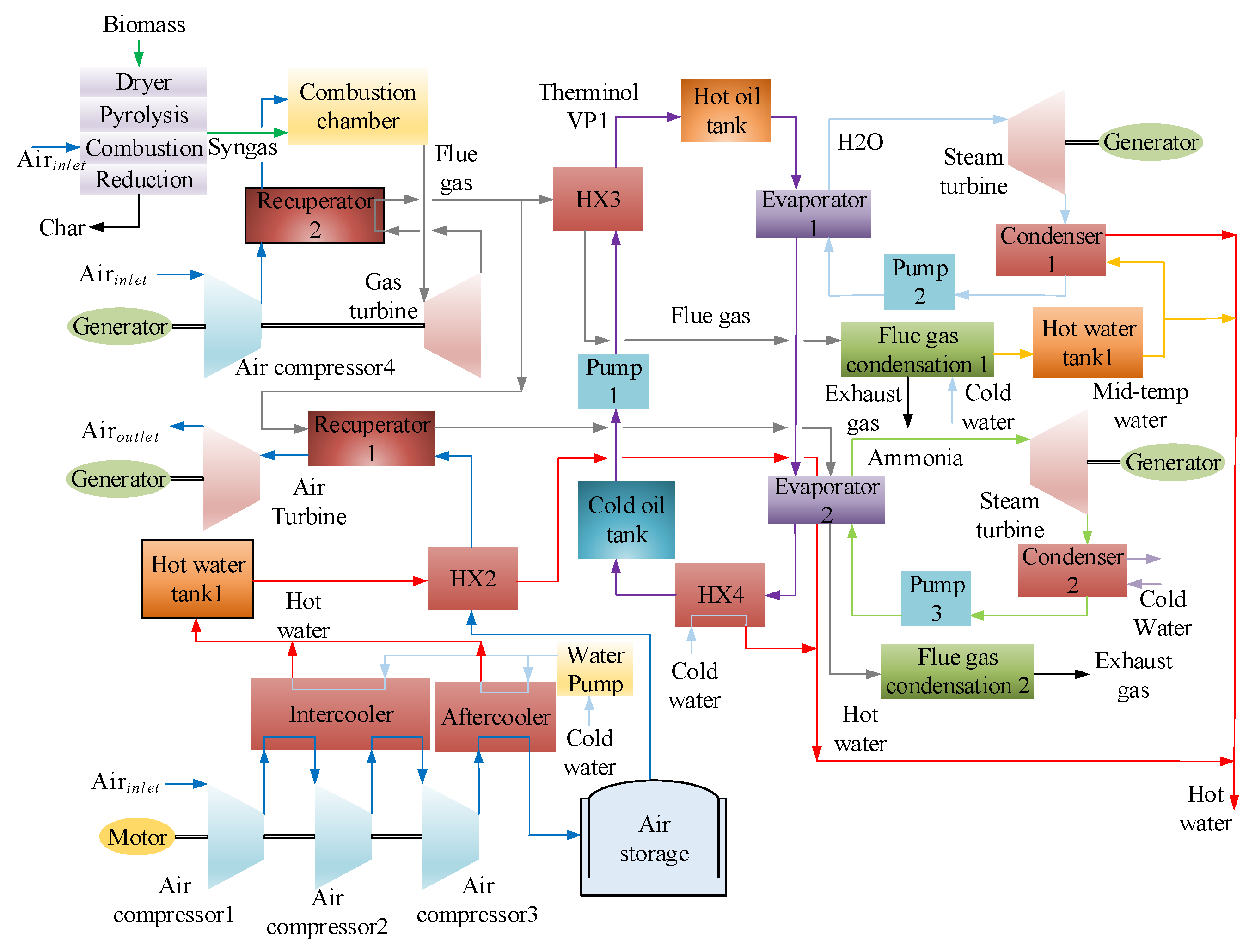
- Since there is a turbine in biomass gasification power generation (BGPG), CAES often shares a turbine with biomass gasification power generation;
- (2)
- When biomass is gasified and burned, and CAES has no combustion chamber, the turbine outlet waste heat of the gasification power generation system is used for heating the CAES turbine inlet air;
- (3)
- The compression heat generated during the energy storage process can be used for purposes such as preheating the gas during biomass gasification, bottom circulation feed water, or drying the biomass;
- (4)
- In some coupling technologies, more heat is produced by CAES and biomass gasification power generation than the heat demand on CAES systems, so the coupling system always provides heat to the outside.
6. Prospects and Challenges of the Coupling Systems
6.1. CAES Coupled with Wind Energy, Solar Energy, and Auxiliary Energy Storage (AES)
6.2. Integrated System
6.3. Challenge
7. Conclusions
Author Contributions
Funding
Data Availability Statement
Conflicts of Interest
Nomenclature
| A-CAES | adiabatic compressed air energy storage |
| AES | auxiliary energy storage |
| BGPG | biomass gasification power generation |
| BIGCC | biomass integrated gasification combined cycle |
| CAES | compressed air energy storage |
| CCHP | combined cooling, heating and power |
| DRCA | downside risk constraints approach |
| EH | energy hub |
| FOWT | floating offshore wind turbine |
| I-CAES | isothermal compressed air energy storage |
| LAES | liquid air energy storage |
| LCOE | levelized cost of energy |
| ORC | organic Rankine cycle |
| PCM | phase change material |
| PHS | pumped hydro storage |
| SC-CAES | supercritical compressed air energy storage |
| TES | thermal energy storage |
| TS-CAES | compressed air energy storage system with thermal storage |
| UWCAES | underwater compressed air energy storage |
| WECS | wind energy conversion system |
References
- Petroleum, B. BP Energy Outlook 2022 Edition; Renouf Publishing Co., Ltd.: London, UK, 2022. [Google Scholar]
- Guo, H.; Xu, Y.; Yan, M.; Kang, H.; Cheng, L.; Huang, L.; Xu, D.; Zhu, Y.; Chen, H. Chapter One—Effect of Thermal Storage and Heat Exchanger on Compressed Air Energy Storage Systems. In Advances in Heat Transfer; Abraham, J.P., Gorman, J.M., Minkowycz, W.J., Eds.; Elsevier: Amsterdam, The Netherlands, 2013; Volume 55, pp. 1–39. [Google Scholar]
- IRENA. Renewable Energy Statistics 2022; The International Renewable Energy Agency: Abu Dhabi, United Arab Emirates, 2022. [Google Scholar]
- Park, H.; Baldick, R. Integration of compressed air energy storage systems co-located with wind resources in the ERCOT transmission system. Int. J. Electr. Power Energy Syst. 2017, 90, 181–189. [Google Scholar] [CrossRef]
- Wu, S.; Zhou, C.; Doroodchi, E.; Moghtaderi, B. Thermodynamic analysis of a novel hybrid thermochemical-compressed air energy storage system powered by wind, solar and/or off-peak electricity. Energy Convers. Manag. 2019, 180, 1268–1280. [Google Scholar] [CrossRef]
- Jin, H.; Liu, P.; Li, Z. Dynamic modeling and design of a hybrid compressed air energy storage and wind turbine system for wind power fluctuation reduction. Comput. Chem. Eng. 2019, 122, 59–65. [Google Scholar] [CrossRef]
- National New Energy Consumption Monitoring and Warning Center. Evaluation and Analysis of National New Energy Power Consumption in the Four Quarters of 2021. Available online: http://www.chinapower.com.cn/zx/hyfx/20220315/138719.html (accessed on 3 March 2022).
- Huang, W.-C.; Zhang, Q.; You, F. Impacts of battery energy storage technologies and renewable integration on the energy transition in the New York State. Adv. Appl. Energy 2023, 9, 100126. [Google Scholar] [CrossRef]
- Chen, H.; Cong, T.N.; Yang, W.; Tan, C.; Li, Y.; Ding, Y. Progress in electrical energy storage system: A critical review. Prog. Nat. Sci. 2009, 19, 291–312. [Google Scholar] [CrossRef]
- Luo, X.; Wang, J.; Dooner, M.; Clarke, J. Overview of current development in electrical energy storage technologies and the application potential in power system operation. Appl. Energy 2014, 137, 511–536. [Google Scholar] [CrossRef] [Green Version]
- Xu, Y.; Chen, H.; Liu, J.; Tan, C. Performance Analysis on an Integrated System of Compressed Air Energy Storage and Electricity Production with Wind-solar Complementary Method. Proc. CSEE 2012, 32, 88–95. (In Chinese) [Google Scholar]
- Tong, Z.; Cheng, Z.; Tong, S. A review on the development of compressed air energy storage in China: Technical and economic challenges to commercialization. Renew. Sustain. Energy Rev. 2021, 135, 110178. [Google Scholar] [CrossRef]
- Li, Y.; Miao, S.; Yin, B.; Han, J.; Zhang, S.; Wang, J.; Luo, X. Combined Heat and Power dispatch considering Advanced Adiabatic Compressed Air Energy Storage for wind power accommodation. Energy Convers. Manag. 2019, 200, 112091. [Google Scholar] [CrossRef]
- Crotogino, F.; Mohmeyer, K.U.; Scharf, R. Huntorf CAES: More than 20 years of successful operation. Nat. Gas 2001, 45, 55. [Google Scholar]
- Nakhamkin, M.; Andersson, L.; Swensen, E.; Howard, J. AEC 110 MW CAES plant: Status of project. ASME J. Eng. Gas Turbines Power 1992, 114, 695–700. [Google Scholar] [CrossRef]
- Hobson, M.J. Conceptual Design and Engineering Studies of Adiabatic Compressed Air Energy Storage (CAES) with Thermal Energy Storage; Nasa Sti/recon Technical Report, N; Pacific Northwest Lab.: Richland, WA, USA; Acres American, Inc.: Columbia, MD, USA, 1981; Volume 82. [Google Scholar]
- Van de Ven, J.D.; Li, P.Y. Liquid piston gas compression. Appl. Energy 2009, 86, 2183–2191. [Google Scholar] [CrossRef]
- Guo, H.; Xu, Y.; Chen, H.; Zhou, X. Thermodynamic characteristics of a novel supercritical compressed air energy storage system. Energy Convers. Manag. 2016, 115, 167–177. [Google Scholar] [CrossRef]
- Morgan, R.; Nelmes, S.; Gibson, E.; Brett, G. Liquid air energy storage—Analysis and first results from a pilot scale demonstration plant. Appl. Energy 2015, 137, 845–853. [Google Scholar] [CrossRef]
- Ameel, B.; T’Joen, C.; De Kerpel, K.; De Jaeger, P.; Huisseune, H.; Van Belleghem, M.; De Paepe, M. Thermodynamic analysis of energy storage with a liquid air Rankine cycle. Appl. Therm. Eng. 2013, 52, 130–140. [Google Scholar] [CrossRef]
- Vasel-Be-Hagh, A.; Carriveau, R.; Ting, D.S.-K. Underwater compressed air energy storage improved through Vortex Hydro Energy. Sustain. Energy Technol. Assess. 2014, 7, 1–5. [Google Scholar] [CrossRef]
- Gouda, E.M.; Fan, Y.; Benaouicha, M.; Neu, T.; Luo, L. Review on Liquid Piston technology for compressed air energy storage. J. Energy Storage 2021, 43, 103111. [Google Scholar] [CrossRef]
- Hashemi-Tilehnoee, M.; Tsirin, N.; Stoudenets, V.; Bushuev, Y.G.; Chorążewski, M.; Li, M.; Li, D.; Leão, J.B.; Bleuel, M.; Zajdel, P.; et al. Liquid piston based on molecular springs for energy storage applications. J. Energy Storage 2023, 68, 107697. [Google Scholar] [CrossRef]
- Guo, H.; Xu, Y.; Guo, C.; Zhang, Y.; Hou, H.; Chen, H. Off-design performance of CAES systems with low-temperature thermal storage under optimized operation strategy. J. Energy Storage 2019, 24, 100787. [Google Scholar] [CrossRef]
- Arabkoohsar, A.; Rahrabi, H.R.; Alsagri, A.S.; Alrobaian, A.A. Impact of Off-design operation on the effectiveness of a low-temperature compressed air energy storage system. Energy 2020, 197, 117176. [Google Scholar] [CrossRef]
- Zhang, Y.; Yang, K.; Li, X.; Xu, J. Thermodynamic analysis of energy conversion and transfer in hybrid system consisting of wind turbine and advanced adiabatic compressed air energy storage. Energy 2014, 77, 460–477. [Google Scholar] [CrossRef]
- Hasan, N.S.; Hassan, M.Y.; Abdullah, H.; Rahman, H.A.; Omar, W.Z.W.; Rosmin, N. Improving power grid performance using parallel connected Compressed Air Energy Storage and wind turbine system. Renew. Energy 2016, 96, 498–508. [Google Scholar] [CrossRef]
- Sriyakul, T.; Jermsittiparsert, K. Risk-controlled economic performance of compressed air energy storage and wind generation in day-ahead, intraday and balancing markets. Renew. Energy 2021, 165, 182–193. [Google Scholar] [CrossRef]
- Zhao, P.; Xu, W.; Zhang, S.; Wang, J.; Dai, Y. Technical feasibility assessment of a standalone photovoltaic/wind/adiabatic compressed air energy storage based hybrid energy supply system for rural mobile base station. Energy Convers. Manag. 2020, 206, 112486. [Google Scholar] [CrossRef]
- Mohammadi, A.; Ahmadi, M.H.; Bidi, M.; Joda, F.; Valero, A.; Uson, S. Exergy analysis of a Combined Cooling, Heating and Power system integrated with wind turbine and compressed air energy storage system. Energy Convers. Manag. 2017, 131, 69–78. [Google Scholar] [CrossRef]
- Sant, T.; Buhagiar, D.; Farrugia, R.N. Evaluating a new concept to integrate compressed air energy storage in spar-type floating offshore wind turbine structures. Ocean Eng. 2018, 166, 232–241. [Google Scholar] [CrossRef]
- Sant, T.; Buhagiar, D.; Farrugia, R.N. Modelling the Dynamic Response and Loads of Floating Offshore Wind Turbine Structures with Integrated Compressed Air Energy Storage. In Proceedings of the ASME 2017 36th International Conference on Ocean, Offshore and Arctic Engineering, Trondheim, Norway, 25–30 June 2017. [Google Scholar]
- Meng, H.; Wang, M.; Olumayegun, O.; Luo, X.; Liu, X. Process design, operation and economic evaluation of compressed air energy storage (CAES) for wind power through modelling and simulation. Renew. Energy 2019, 136, 923–936. [Google Scholar] [CrossRef]
- Ghorbani, B.; Mehrpooya, M.; Ardehali, A. Energy and exergy analysis of wind farm integrated with compressed air energy storage using multi-stage phase change material. J. Clean. Prod. 2020, 259, 120906. [Google Scholar] [CrossRef]
- Abouzeid, S.I.; Guo, Y.; Zhang, H.-C. Cooperative control framework of the wind turbine generators and the compressed air energy storage system for efficient frequency regulation support. Int. J. Electr. Power Energy Syst. 2021, 130, 106844. [Google Scholar] [CrossRef]
- Succar, S.; Denkenberger, D.C.; Williams, R.H. Optimization of specific rating for wind turbine arrays coupled to compressed air energy storage. Appl. Energy 2012, 96, 222–234. [Google Scholar] [CrossRef]
- Yang, Z.; Wang, Z.; Ran, P.; Li, Z.; Ni, W. Thermodynamic analysis of a hybrid thermal-compressed air energy storage system for the integration of wind power. Appl. Therm. Eng. 2014, 66, 519–527. [Google Scholar] [CrossRef]
- Zhao, P.; Wang, P.; Xu, W.; Zhang, S.; Wang, J.; Dai, Y. The survey of the combined heat and compressed air energy storage (CH-CAES) system with dual power levels turbomachinery configuration for wind power peak shaving based spectral analysis. Energy 2021, 215, 119167. [Google Scholar] [CrossRef]
- Zhao, P.; Gou, F.; Xu, W.; Shi, H.; Wang, J. Multi-objective optimization of a hybrid system based on combined heat and compressed air energy storage and electrical boiler for wind power penetration and heat-power decoupling purposes. J. Energy Storage 2023, 58, 106353. [Google Scholar] [CrossRef]
- Sun, H.; Luo, X.; Wang, J. Feasibility study of a hybrid wind turbine system—Integration with compressed air energy storage. Appl. Energy 2015, 137, 617–628. [Google Scholar] [CrossRef] [Green Version]
- Saadat, M.; Shirazi, F.A.; Li, P.Y. Modeling and control of an open accumulator Compressed Air Energy Storage (CAES) system for wind turbines. Appl. Energy 2015, 137, 603–616. [Google Scholar] [CrossRef]
- Zhang, X.; Chen, H.; Xu, Y.; Zhou, X.; Guo, H. Isothermal Compressed Air Energy Storage. In Energy Engineering, Compressed Air Energy Storage: Types, Systems and Applications; Institution of Engineering and Technology: London, UK, 2021; pp. 29–54. [Google Scholar]
- Rahmanifard, H.; Plaksina, T. Hybrid compressed air energy storage, wind and geothermal energy systems in Alberta: Feasibility simulation and economic assessment. Renew. Energy 2019, 143, 453–470. [Google Scholar] [CrossRef]
- Li, Y.; Wang, J.; Han, Y.; Zhao, Q.; Fang, X.; Cao, Z. Robust and opportunistic scheduling of district integrated natural gas and power system with high wind power penetration considering demand flexibility and compressed air energy storage. J. Clean. Prod. 2020, 256, 120456. [Google Scholar] [CrossRef]
- Astolfi, M.; Guandalini, G.; Belloli, M.; Hirn, A.; Silva, P.; Campanari, S. Preliminary Design and Performance Assessment of an Underwater Compressed Air Energy Storage System for Wind Power Balancing. J. Eng. Gas Turbines Power 2020, 142, 091001. [Google Scholar] [CrossRef]
- Jalili, M.; Sedighizadeh, M.; Fini, A.S. Stochastic optimal operation of a microgrid based on energy hub including a solar-powered compressed air energy storage system and an ice storage conditioner. J. Energy Storage 2021, 33, 102089. [Google Scholar] [CrossRef]
- Li, P.; Hu, Q.; Sun, Y.; Han, Z. Thermodynamic and economic performance analysis of heat and power cogeneration system based on advanced adiabatic compressed air energy storage coupled with solar auxiliary heat. J. Energy Storage 2021, 42, 103089. [Google Scholar] [CrossRef]
- Kandezi, M.S.; Naeenian, S.M.M. Thermodynamic and economic analysis of a novel combination of the heliostat solar field with compressed air energy storage (CAES); a case study at San Francisco, USA. J. Energy Storage 2022, 49, 104111. [Google Scholar] [CrossRef]
- Yang, M.; Duan, L.; Tong, Y.; Jiang, Y. Study on design optimization of new liquified air energy storage (LAES) system coupled with solar energy. J. Energy Storage 2022, 51, 104365. [Google Scholar] [CrossRef]
- Wang, X.; Yang, C.; Huang, M.; Ma, X. Off-design performances of gas turbine-based CCHP combined with solar and compressed air energy storage with organic Rankine cycle. Energy Convers. Manag. 2018, 156, 626–638. [Google Scholar] [CrossRef]
- Alirahmi, S.M.; Mousavi, S.B.; Razmi, A.R.; Ahmadi, P. A comprehensive techno-economic analysis and multi-criteria optimization of a compressed air energy storage (CAES) hybridized with solar and desalination units. Energy Convers. Manag. 2021, 236, 114053. [Google Scholar] [CrossRef]
- Sun, S.; Kazemi-Razi, S.M.; Kaigutha, L.G.; Marzband, M.; Nafisi, H.; Al-Sumaiti, A.S. Day-ahead offering strategy in the market for concentrating solar power considering thermoelectric decoupling by a compressed air energy storage. Appl. Energy 2022, 305, 117804. [Google Scholar] [CrossRef]
- Wen, P.; Xie, Y.; Huo, L.; Tohidi, A. Optimal and stochastic performance of an energy hub-based microgrid consisting of a solar-powered compressed-air energy storage system and cooling storage system by modified grasshopper optimization algorithm. Int. J. Hydrog. Energy 2022, 47, 13351–13370. [Google Scholar] [CrossRef]
- Su, D. Comprehensive thermodynamic and exergoeconomic analyses and multi-objective optimization of a compressed air energy storage hybridized with a parabolic trough solar collectors. Energy 2022, 244, 122568. [Google Scholar] [CrossRef]
- Mohammadi, A.; Mehrpooya, M. Exergy analysis and optimization of an integrated micro gas turbine, compressed air energy storage and solar dish collector process. J. Clean. Prod. 2016, 139, 372–383. [Google Scholar] [CrossRef]
- Mousavi, S.B.; Ahmadi, P.; Pourahmadiyan, A.; Hanafizadeh, P. A comprehensive techno-economic assessment of a novel compressed air energy storage (CAES) integrated with geothermal and solar energy. Sustain. Energy Technol. Assess. 2021, 47, 101418. [Google Scholar] [CrossRef]
- Udell, K.; Beeman, M. Thermodynamic Analysis of an Advanced Solar-Assisted Compressed Air Energy Storage System. In Proceedings of the ASME 2016 10th International Conference on Energy Sustainability Collocated with the ASME 2016 Power, Conference and the ASME 2016 14th International Conference on Fuel Cell Science, Engineering and Technology, Charlotte, NC, USA, 26–30 June 2016; American Society of Mechanical Engineers: New York, NY, USA, 2016; Volume 2, p. V002T01A006. [Google Scholar]
- Guo, H.; Xu, Y.; Sun, J.; Chen, H. A Temperature-Controlled Off-Design Operation Strategy Based on Compressed Air Energy Storage System with Thermal Storage. Chinese Patent CN202010059722.X, 30 April 2021. (In Chinese). [Google Scholar]
- Wang, X.; Yang, C.; Huang, M.; Ma, X. Multi-objective optimization of a gas turbine-based CCHP combined with solar and compressed air energy storage system. Energy Convers. Manag. 2018, 164, 93–101. [Google Scholar] [CrossRef]
- Garrison, J.B.; Webber, M.E. An Integrated Energy Storage Scheme for a Dispatchable Solar and Wind Powered Energy System and Analysis of Dynamic Parameters; American Society of Mechanical Engineers: New York, NY, USA, 2011. [Google Scholar]
- Ji, W.; Zhou, Y.; Sun, Y.; Zhang, W.; An, B.; Wang, J. Thermodynamic analysis of a novel hybrid wind-solar-compressed air energy storage system. Energy Convers. Manag. 2017, 142, 176–187. [Google Scholar] [CrossRef]
- Wu, Y.; Zhang, T. Risk assessment of offshore wave-wind-solar-compressed air energy storage power plant through fuzzy comprehensive evaluation model. Energy 2021, 223, 120057. [Google Scholar] [CrossRef]
- Denholm. Enabling Technologies for High Penetration of Wind and Solar Energy; ASME International Conference on Energy Sustainability: New York, NY, USA, 2011. [Google Scholar]
- Marano, V.; Rizzo, G.; Tiano, F.A. Application of dynamic programming to the optimal management of a hybrid power plant with wind turbines, photovoltaic panels and compressed air energy storage. Appl. Energy 2012, 97, 849–859. [Google Scholar] [CrossRef]
- Xue, X.; Li, J.; Liu, J.; Wu, Y.; Chen, H.; Xu, G.; Liu, T. Performance evaluation of a conceptual compressed air energy storage system coupled with a biomass integrated gasification combined cycle. Energy 2022, 247, 123442. [Google Scholar] [CrossRef]
- Diyoke, C.; Wu, C. Thermodynamic analysis of hybrid adiabatic compressed air energy storage system and biomass gasification storage (A-CAES + BMGS) power system. Fuel 2020, 271, 117572. [Google Scholar] [CrossRef]
- Diyoke, C.; Aneke, M.; Wang, M.; Wu, C. Techno-economic analysis of wind power integrated with both compressed air energy storage (CAES) and biomass gasification energy storage (BGES) for power generation. RSC Adv. 2018, 8, 22004–22022. [Google Scholar] [CrossRef] [Green Version]
- Lashgari, F.; Babaei, S.M.; Pedram, M.Z.; Arabkoohsar, A. Comprehensive analysis of a novel integration of a biomass-driven combined heat and power plant with a compressed air energy storage (CAES). Energy Convers. Manag. 2022, 255, 115333. [Google Scholar] [CrossRef]
- Zhang, X.; Zeng, R.; Deng, Q.; Gu, X.; Liu, H.; He, Y.; Mu, K.; Liu, X.; Tian, H.; Li, H. Energy, exergy and economic analysis of biomass and geothermal energy based CCHP system integrated with compressed air energy storage (CAES). Energy Convers. Manag. 2019, 199, 111953. [Google Scholar] [CrossRef]
- Razmi, A.R.; Afshar, H.H.; Pourahmadiyan, A.; Torabi, M. Investigation of a combined heat and power (CHP) system based on biomass and compressed air energy storage (CAES). Sustain. Energy Technol. Assess. 2021, 46, 101253. [Google Scholar] [CrossRef]
- Hai, T.; Zoghi, M.; Javaherdeh, K. 4E analysis and optimization of a biomass-fired waste-to-energy plant integrated with a compressed air energy storage system for the multi-generation purpose. Fuel 2023, 348, 128457. [Google Scholar] [CrossRef]
- Gur, T.M. Review of Electrical Energy Storage Technologies, Materials and Systems: Challenges and Prospects for Large-Scale Storage. Energy Environ. Sci. 2018, 11, 2696–2767. [Google Scholar] [CrossRef]
- Zhang, Y.; Xu, Y.; Zhou, X.; Guo, H.; Zhang, X.; Chen, H. Compressed air energy storage system with variable configuration for accommodating large-amplitude wind power fluctuation. Appl. Energy 2019, 239, 957–968. [Google Scholar] [CrossRef]
- Sedighizadeh, M.; Esmaili, M.; Mousavi-Taghiabadi, S.M. Optimal joint energy and reserve scheduling considering frequency dynamics, compressed air energy storage, and wind turbines in an electrical power system. J. Energy Storage 2019, 23, 220–233. [Google Scholar] [CrossRef]
- Johlas, H.; Witherby, S.; Doyle, J.R. Storage requirements for high grid penetration of wind and solar power for the MISO region of North America: A case study. Renew. Energy 2020, 146, 1315–1324. [Google Scholar] [CrossRef]


| Compression Heat Is Used | With Regenerator | With Fuel Input | Provide By-Products | Provide Heating/Cooling Capacity | With Bottom Cycle and Its Type | |
|---|---|---|---|---|---|---|
| Mehdi et al. [46] | N | Y | Y | N | N | N |
| Li et al. [47] | Y | N | N | N | Y | N |
| Kandezi et al. [48] | N | Y | N | N | Y | N |
| Yang et al. [49] | Y + N | Y | N | N | N | N |
| Wang et al. [50] | N | N | N | N | Y | Y, ORC |
| Wang et al. [50] | N | Y | N | N | Y | N |
| Wu et al. [5] | N | Y | N | Oxygen | Y | N |
| Alirahmi et al. [51] | N | Y | N | Fresh water | Y | N |
| Sun et al. [52] | N | N | Y | N | Y | N |
| Wen et al. [53] | N | Y | Y | N | N | N |
| Su [54] | Y | Y | N | N | N | N |
| Mohammadi et al. [55] | N | Y | Y | N | N | N |
| Mousavi et al. [56] | Y | Y | N | N | Y | Y, ORC |
| Udell et al. [57] | Y | N | N | N | N | N |
| References | Biomass Gasification Exists in the Energy Storage Process | Biomass Gasification Exists in the Energy Release Process | Turbine Is Shared for CAES and BGPG | Outlet Heat of the BGPG Turbine Reheats the CAES Turbine | Supply Heat to the Outside |
|---|---|---|---|---|---|
| Xue et al. [65] | Y | Y | Y | N | N |
| Lashgari et al. [68] | Y | Y | N | Y | Y |
| Zhang et al. [69] | N | Y | Y | N | Y |
| Diyoke et al. [66] | Y | N | N | Y | Y |
| Razmi et al. [70] | Y | Y | Y | N | Y |
| Hai et al. [71] | Y | Y | N | N | Y |
Disclaimer/Publisher’s Note: The statements, opinions and data contained in all publications are solely those of the individual author(s) and contributor(s) and not of MDPI and/or the editor(s). MDPI and/or the editor(s) disclaim responsibility for any injury to people or property resulting from any ideas, methods, instructions or products referred to in the content. |
© 2023 by the authors. Licensee MDPI, Basel, Switzerland. This article is an open access article distributed under the terms and conditions of the Creative Commons Attribution (CC BY) license (https://creativecommons.org/licenses/by/4.0/).
Share and Cite
Guo, H.; Kang, H.; Xu, Y.; Zhao, M.; Zhu, Y.; Zhang, H.; Chen, H. Review of Coupling Methods of Compressed Air Energy Storage Systems and Renewable Energy Resources. Energies 2023, 16, 4667. https://doi.org/10.3390/en16124667
Guo H, Kang H, Xu Y, Zhao M, Zhu Y, Zhang H, Chen H. Review of Coupling Methods of Compressed Air Energy Storage Systems and Renewable Energy Resources. Energies. 2023; 16(12):4667. https://doi.org/10.3390/en16124667
Chicago/Turabian StyleGuo, Huan, Haoyuan Kang, Yujie Xu, Mingzhi Zhao, Yilin Zhu, Hualiang Zhang, and Haisheng Chen. 2023. "Review of Coupling Methods of Compressed Air Energy Storage Systems and Renewable Energy Resources" Energies 16, no. 12: 4667. https://doi.org/10.3390/en16124667