Review

Review on Salt Hydrate Thermochemical Heat Transformer

Chemical and Materials Engineering Department, University of Auckland, Auckland 1010, New Zealand
*
Author to whom correspondence should be addressed.
Energies 2023, 16(12), 4668; https://doi.org/10.3390/en16124668
Submission received: 17 April 2023 / Revised: 25 May 2023 / Accepted: 9 June 2023 / Published: 12 June 2023
(This article belongs to the Section J1: Heat and Mass Transfer)

Abstract

:
The industrial sector utilizes approximately 40% of global energy consumption. A sizeable amount of waste energy is rejected at low temperatures due to difficulty recovering with existing technologies. Thermochemical heat transformers (THT) can play a role in recovering low-temperature industrial waste heat by storing it during high supply and discharging it on demand at a higher temperature. Thus, THT will enable waste heat reintegration into industrial processes, improving overall energy efficiency and lowering greenhouse gas emissions from the industrial sector. Salt hydrate is a promising thermochemical material (TCM) because it requires a low charging temperature which can be supplied by waste heat. Furthermore, its non-toxic nature allows the implementation of a simpler and less costly open system. Despite extensive research into salt hydrate materials for thermochemical energy storage (TCES) applications, a research gap is identified in their use in THT applications. This paper aims to provide a comprehensive literature review of the advancement of THT applications, particularly for systems employing salt hydrates material. A discussion on existing salt hydrate materials used in the THT prototype will be covered in this paper, including the challenges, opportunities, and suggested future research works related to salt hydrate THT application.

1. Introduction

The industrial sector is one of the most significant energy users, which globally consumed 40% of total energy or approximately 241 quadrillion BTU in 2020 [1]. The greenhouse gasses (GHG) emission is proportional to the amount of energy used [2]. However, even the most optimized industrial processes generate waste heat [3]. Therefore, in order to increase industrial energy efficiency, waste heat must be recovered [2]. Industrial waste heat recovery has been recognized as one of the paths for GHG mitigation by the Intergovernmental Panel on Climate Change (IPCC) [4]. Published studies on industrial waste heat potential estimation revealed that the percentage of industrial waste heat out of the industrial sector’s energy consumption is 5.5–10.9% in the UK [5], 13% in Germany [6], 17.3% in Taiwan [7], and 9.5% in the European Union (EU) [8]. Recovery of this amount of energy could substantially improve industrial energy efficiency and reduce global GHG emissions.
There is no formal convention on the classification of industrial waste heat. However, it is typically classified based on its temperature level. Johnson et al. [2] categorized the industrial waste heat into high-temperature (>649 °C), medium-temperature (232–649 °C), and low-temperature (<232 °C). While Blest et al. [9,10] used the following temperature range for the classification: high-temperature (>500 °C), medium-temperature (100–500 °C), and low-temperature (<100 °C). High and medium-temperature waste heat is typically easy to recover for use, whereas low-temperature waste heat is the most difficult to recover [2], which led to a limited re-utilization [11]. Several industries generating low-temperature waste heat are petrochemical, food-processing, textile, pulp and paper, marine transportation, and LNG [12]. The estimated amount of low-temperature industrial waste heat is quite considerable. In the EU, approximately one-third of the industrial waste heat belongs to the low-temperature grade [8].
Due to the lack of efficient energy recovery technology, low-temperature industrial waste heat has frequently been discarded, which has caused thermal pollution and turned into an environmental issue [13]. As a result, low-temperature industrial waste heat recovery represents a crucial research subject and challenging task in the energy field [12,13]. Thermal cycles (e.g., Organic Rankine Cycle and Kalina Cycle) are typically used to recover low-temperature industrial waste heat. However, such technology has shortcomings of low efficiency and complexity, which drive attempts to investigate and develop alternative technologies [14].
One of the technologies that can prevent the disposal of industrial waste heat into the environment is thermal energy storage (TES). With TES, the waste energy can be stored for later use [15]. Based on the type of energy stored in the TES system, it is classified into sensible, latent, and sorption/chemical TES [16]. Sensible TES stores the energy through temperature increases of the storage material [17], such as in domestic hot water applications [18]. While in latent TES, the energy is stored by melting a phase change material (PCM) [19]. An example of a latent TES application is the integration of PCM into building material to reduce variation of internal temperature in lightweight buildings [20].
Thermochemical heat transformer (THT) is part of sorption/chemical TES, and it is a promising emerging technology for storing and re-utilizing low-temperature industrial waste heat. Numerous thermochemical material (TCM), especially salt hydrate materials, requires a charging temperature of 105–115 °C [21], which is available from low-grade industrial waste heat. THT can store available energy during a high supply period and discharge it on demand at a higher temperature [22], enabling its reintegration into industrial processes [23]. The advantages of THT compared to a conventional vapour compression heat pump are it can be directly driven by the waste heat and does not require electrical energy to generate the temperature upgrade [24] and it can provide energy storage function during fluctuation of waste heat supply [11].
This paper aims to provide a literature review of THT applications, specifically those related to salt hydrates. There are a few review papers on THT research in the literature [24,25,26,27,28]. However, to our knowledge, this is the first review of THT application specific to salt hydrate material. The content of this paper is arranged into six sections. Section 1 is an introduction to the topic. Section 2 describes the THT working principle, working pair and system type. Section 3 reviews salt hydrate material characteristics required for THT application. Section 4 details recent research advancement of salt hydrate THT. Section 5 outlines the research gaps, challenges, and opportunities in salt hydrate THT research, followed by the conclusion.

2. Thermochemical Heat Transformer (THT)

2.1. Working Principle

In the Thermal Energy Storage (TES) classification, thermochemical and physisorption are grouped under Sorption/Chemical TES. Thermochemical is it is further divided into chemical reaction (without sorption) and chemical sorption (or chemisorption) [16,29]. The chemical reaction (without sorption) mechanism is typically described as follows:
A + heat   B + C
The decomposition of compound A through an endothermic reaction will result in chemical potential energy stored in the chemical substances B and C. This stored energy is then produced through a reversible reaction between B and C to regenerate compound A.
While the chemical sorption mechanism is typically written as follows:
AB + heat   A + B
Sorption is a process where gas or vapour (sorbate) is fixated by a liquid/solid substance (sorbent). A and B are called the sorption working pair generated from compound AB’s dissociation through an endothermic reaction. A and B substances can hold chemical potential energy when stored separately. The stored energy in the thermochemical energy system is released when compound AB is regenerated through an exothermic reaction between substances A and B. Salt hydrate material belongs to this chemical sorption category.
The minimum temperature required to allow endothermic reaction is called “charging or decomposition or regeneration temperature” (or “dehydration temperature” in a salt hydrate system). In contrast, the temperature that resulted in the exothermic reaction is called “discharging or synthesis or production temperature” (or “hydration temperature” in a salt hydrate system).
The thermochemical energy system has two applications: thermochemical energy storage system (TCES) and Thermochemical Heat Transformer (THT). In TCES, the stored energy from the endothermic reaction is released during the exothermic reaction at a lower discharging temperature (TM) compared to its charging temperature (TH), as shown in Figure 1a,b. Depending on the utilization of the energy, TCES can be applied for heating and cooling purposes, which are mainly applied for building use. In the literature, the terminology of Thermochemical Heat Storage (TCHS) is also often used to describe the TCES system.
The working principle of TCES for heating application is presented in Figure 1a. The useful heat is generated during the exothermic reaction of sorbent and sorbate and the heat is released at a lower temperature than heat input during the endothermic reaction. The SrCl2-cement composite lab-scale reactor developed by Clark et al. [30] is an example of a salt hydrate TCES for heating applications. The salt hydrate is dehydrated in this reactor at a charging temperature below 150 °C. Subsequently, the heat generated during the hydration process at a temperature of 32–37 °C makes it suitable for building’s space heating applications.
TCES cooling application can be performed through three methods [31]. In the most common method, the cooling effect is produced during the evaporation of the sorbate fluid before reacting with the sorbent [32] the working principle is shown in Figure 1b. This method’s thermochemical cooling applications typically employ inorganic salt (such as BaCl2) and ammonia working pairs [32,33]. The other methods utilize the cooling effect generated during an endothermic reaction (decomposition phase) [34] or during the dissolution of endothermic salts [35].
Meanwhile, in the THT application, the stored energy is typically released at a higher temperature (TH) than its charging temperature (TM) [25], as shown in Figure 1c. THT application will enable the utilization of low-grade heat from solar thermal or industrial waste heat to meet industrial heating demand at higher temperatures [28,36]. For example, in the THT application using SrCl2/NH3 working pair, the reactor can be charged by solar thermal at 96 °C. During the discharging phase, the stored thermal energy in the reactor can be upgraded to a heat output of 146 °C through a reaction with ammonia evaporated by solar thermal at 96 °C [36]. This review paper is focused on the THT application of stored thermochemical energy. It is observed in the literature that terminologies such as “thermochemical heat pump”, “chemical heat pump”, or “sorption heat pump” are also used. However, only systems that conform with the THT definition of discharging temperature is higher than charging temperature and/or thermochemical application to upgrade low-temperature waste heat to usable heat for industrial use (>100 °C) will be included in the scope of this paper.

2.2. Reaction Phase and Working Pairs

The THT system can be further classified based on the reaction phase into liquid-gas and solid-gas [25]. The liquid-gas THT is often called Absorption Heat Transformer. LiBr/H2O and NH3/H2O are the most common working pairs in liquid-gas THT and have achieved commercial application [28]. The liquid-gas system is frequently regarded as more suitable for continuous operations than the solid-gas system. The argument was that the charging and discharging phases could be done in different reactors in a liquid gas system because reactant and product removal could be done continuously. Meanwhile, in a solid-gas system, the charging and discharging phases occurred in the same reactor sequentially [25].
In contrast to the above argument, a continuous operation in a solid-gas system can be established by having two sets of reactors. While the first reactor is discharging, the second reactor is charging so that it will be ready when the first reactor’s energy storage is exhausted. Moreover, additional benefits of the solid-gas system include high heat storage capacity, a broad range of operating temperatures, a long storage period, and self-separation between the sorbent and sorbate [24,37]. The classification of the working pairs of the solid-gas THT system is given in Table 1.
The most applied working pairs for THT applications are metal hydride/hydrogen and chloride salts/ammonia [26]. In single-stage metal hydride/hydrogen THT application, the resulting temperature upgrade is in the range of 15–90 °C (Li et al. (2005), as cited in [26]). The ammonia-based system reactions cover a wide range of operating conditions (up to 50 bar pressure and −50 to 300 °C. They possess a high energy density (for example, 510 Wh/kg for NiCl2/NH3 working pairs) and provide a thermal potential of up to 250 °C in THT applications [38]. The resulting temperature upgrade of two connected chloride salts/ammonia THT reactors system ranges between 25 to 80 °C (Neveu and Castaiang (1993), as cited in [25]). The main concern of ammonia working pairs is cost and safety as it operates at high temperatures [39].
Compared to other working pairs, the salt hydrate/water vapour system requires a relatively low charging temperature, which can be supplied by low-grade heat such as solar thermal or industrial waste heat [17,37,40]. Additionally, water vapour is a non-toxic substance that allows the implementation of an open system since it can be immediately discharged into the environment.

2.3. Open vs. Closed System Solid-Gas THT

The open and closed system definition of a THT is similar to that used for the TCES system. The definition refers to the boundary and operating pressure of the system. An open system THT operates at atmospheric pressure and gas reactant (sorbate vapour) is not stored in the system. While in a closed system THT, the sorbate vapour is circulated in a closed loop; therefore, there is no mass exchange between the THT system and the environment. The operating pressure of a closed-system THT is adjustable, and it could be high pressure or vacuum [17]. The typical schematic of a closed-system solid-gas sorption THT is shown in Figure 2.
The closed system consists of two reactors, a switching valve, an evaporator, and a condenser [23]. The TCM (solid sorbent) is placed inside the reactors, and using two paired reactors enables continuous heat output by cycling between the charging and discharging phases. During the charging (heat storage) phase, waste heat is supplied to the reactor to enable the endothermic reaction. The desorbed sorbate vapour flows from the reactor to the condenser at ambient temperature and condenses to the liquid phase. The valve is switched after the completion of the charging phase. During the discharging (heat release) phase, the liquid sorbate is evaporated by waste heat in the evaporator and delivered to the reactor, where it undergoes an exothermic reaction and generates the heat for use.
Meanwhile, an open system operates without a condenser and evaporator; therefore, it does not involve phase change of the sorbate. The schematic of an open-system THT is shown in Figure 3. An open system only applies to environmentally friendly sorbate, as the sorbate vapour is taken from and released directly into the ambient. An open system is simpler due to less equipment required (no extra storage tank, vacuum or cold sink), potentially leading to a higher energy density on a system level, more straightforward handling and less expensive equipment [22,39].

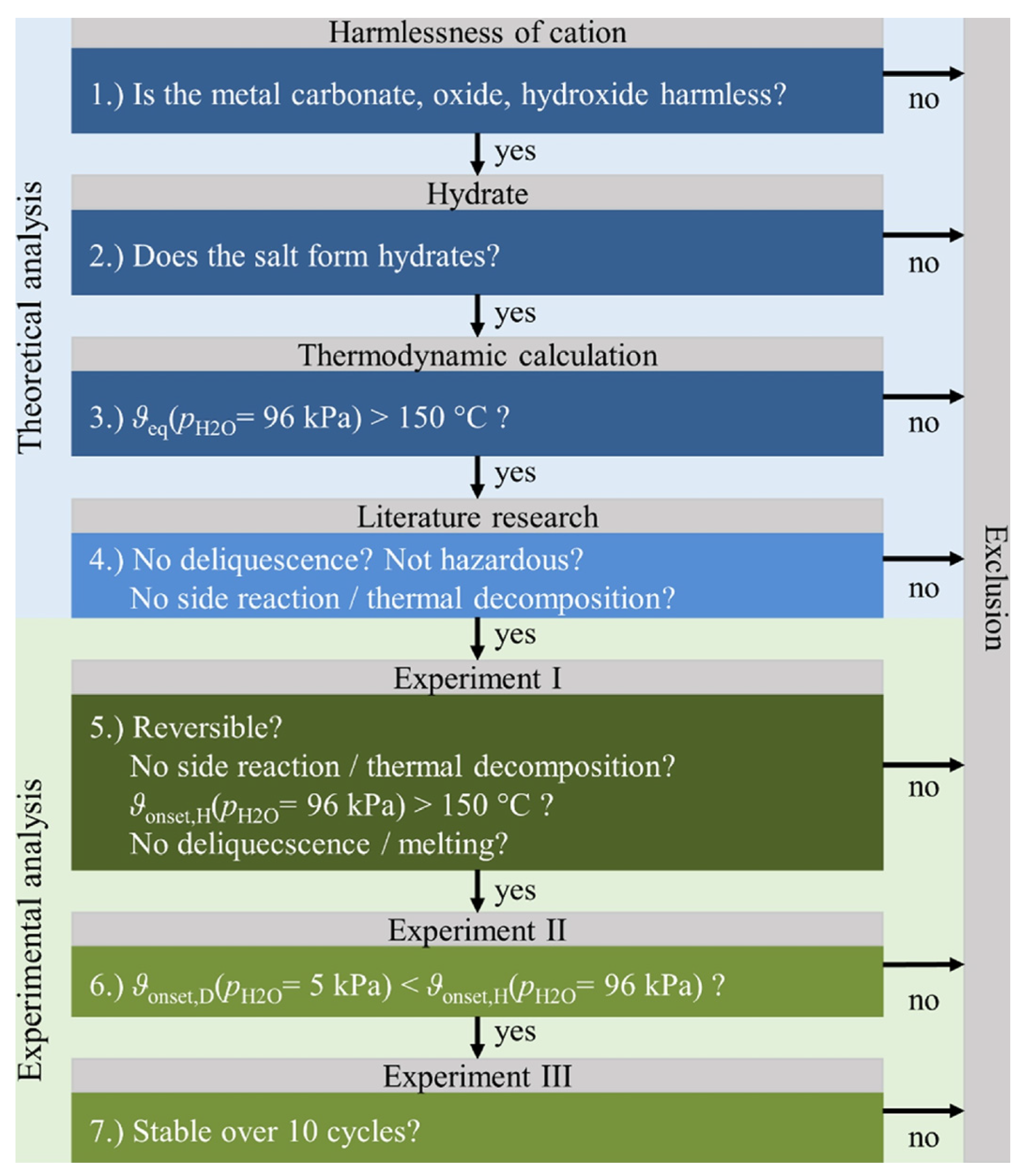
3. Salt Hydrate Characteristics Required for THT Application

Salt hydrate has been extensively experimented with for TCES applications. It is observed in the literature that salt hydrates are utilized as TCM in TCES applications in four different forms. Table 2 provides a summary of these forms and the experimented materials in each category.
The main application for salt hydrate TCES is to provide space heating for buildings. In this application, the sorbate used during the hydration (charging) phase is humid air at ambient temperature. Several screening processes have been attempted by researchers to find the most suitable salt hydrate for TCES in building applications. N’Tsoukpoe et al. [21] performed a systemic screening of 125 salt hydrates for TCES application at low temperatures (dehydration temperature less than 105 °C). The screening process was conducted in three steps: safety criteria (toxicity and explosion risk), basic TGA and DCS analysis at 1 K/min and 10 K/min heating rate, and validation of TGA and DCS analysis for screened salt hydrate under water vapour pressure of 21 mbar. A total of 80 salt hydrates were screened out in the first step, and an additional 28 salt hydrates were screened out in the second step. From the remaining 17 salt hydrates undertaken in the third screening step, three salt hydrates (SrBr2.6H2O, LaCl3.7H2O and MgSO4.6H2O) were concluded as the most promising material for low-temperature TCES application.
Furthermore, Donkers et al. [64] developed a database consisting of 262 salt hydrates and 563 salt hydrate reactions. They performed a screening based on thermodynamic criteria that are most suitable for domestic application seasonal heat storage, i.e., discharging temperature of >50 °C, charging temperature of <120 °C, and energy density of >1.3 GJ/m3. The screening process based on these constraints resulted in 25 salt hydrate reactions. A further analysis of the shortlisted reactions which included consideration of material cost, safety, stability and kinetics of reaction concluded that K2CO3 was the most promising material for both open and closed systems.
Refer to the published works on the investigation of TCM for TCES applications, an ideal TCM shall have the following characteristics:
  • High energy storage density at the operating temperature [65,66].
  • Low charging temperature [64,65,67].
  • Short charging period [65].
  • High thermal conductivity to ease heat transfer [68].
  • High uptake and affinity of sorbate vapour to solid sorbent assist the mass transfer [65].
  • Safe and easy to handle (all components involved in the reversible reaction (salt hydrate, solid sorbent, and sorbate vapour) are not toxic, non-poisonous and non-corrosive) [65,67,69].
  • Mechanically and chemically stable to ensure a repeatable cycle (good cyclability) [69].
  • Inexpensive material to ensure economic feasibility at large-scale applications [65,70].
All characteristics listed above also apply to the salt hydrate material used in the THT application. In the THT system, the charging phase happens at a high temperature similar to the TCES charging temperature. However, as the main application of THT is for upgrading waste heat, the initial temperature during discharging phase happens at a higher temperature (waste heat temperature) than TCES (ambient temperature). The resulting discharging temperature will also typically be higher than the charging temperature. Therefore, the salt hydrate material for THT application shall possess the following additional characteristics:
  • Adequate thermal upgrade/temperature lift (i.e., the resulting discharge temperature fits the THT application requirement) [69,71,72].
  • Thermally stable at high-temperature working conditions (no side reaction/deliquescence/melting/thermal decomposition during charging and discharging phase) [25,71].
The only screening work of salt hydrate material, specifically for THT application, was done by Richter et al. [71]. This work included 308 inorganic salts, intending to select the most suitable salt hydrate to thermally upgrade the industrial waste heat to a temperature between 150 °C and 300 °C. The screening method includes theoretical and experimental analysis; the steps are shown in Figure 4.
The first step in theoretical analysis eliminated carcinogens or harmful salts, leaving 253 inorganic salts to proceed to the next step. Only 113 salts that generate hydrates were chosen in the second step. In the third step, a thermodynamic calculation was done using data from the literature. Only salt hydrates with an equilibrium temperature at atmospheric pressure greater than 150 °C can advance to the following step. The last step of theoretical analysis evaluated the thermal stability of the remaining 47 salt hydrates, such as side reactions, thermal decomposition, and deliquescence. The result was 32 salt hydrates passed to experimental assessment.
The experiment was conducted by using simultaneous thermal analysis (STA). Four parameters are analyzed in the first experiment: dehydration/hydration reaction reversibility, side reactions or thermal decomposition, deliquescence/melting, and hydration reaction completion and temperature. The reaction reversibility test started by gradually heating the material to 300 °C under nitrogen purge gas, representing the dehydration phase. The purge gas was then switched to pure water vapour at atmospheric pressure while gradually cooling the material to 120 °C (minimum), representing the hydration phase.
The first experiment results revealed only six salt hydrates completed the reversible reactions, which are MgSO4, CaSO4, SrCl2, SrBr2, MnBr2, and ZnSO4. The second experiment investigated the reaction hysteresis. The six remaining salt hydrates were dehydrated at a partial vapour pressure of 5 kPa to simulate charging by humid air in summer. This work concluded that only SrBr2·H2O and CaSO4.0.5H2O have the possibility of thermal upgrade. Between these two, SrBr2·H2O shows a more stable performance after ten dehydration/hydration cycles.
The conclusion of the screening work by Richter et al. [71] is not encouraging, as it resulted in only two suitable salt hydrates, in which SrBr2 is the most suitable material. SrBr2 is an expensive salt, so its applications as TCM may not be economical [73]. However, it is also important to note that this screening work was only done in a single pure salt form. Several salt hydrates were eliminated in the earlier steps due to thermal decomposition and deliquescence. Referring to TCES applications research, the performance of salt hydrate could be enhanced by combination with other salt hydrates [48,50] or the development of composite material with a porous matrix [67,74]. The salt hydrate composite materials exhibit the following advantages:
  • Salt particles are dispersed across the pores, and the interface area for the reaction is multiplied, enhancing reaction kinetics [67,75].
  • Moisture diffusion channels are created to improve heat and mass transfer [67,75].
  • Prevent salt agglomeration and improve stability [67,76].
  • Improve mechanical strength to stabilize the salt [77].
  • Accommodates the material swelling and shrinking over cycles [37]
  • Improve the thermal conductivity of the reactor bed, leading to a more efficient heat transfer [75].
  • Practical pressure drop through composite material may speed up the reaction [75].
Therefore, more salt hydrate materials may be suitable for THT when applied in forms other than a single pure salt, which requires a thorough investigation.

4. Recent Advancement of Salt Hydrate-Based THT Research

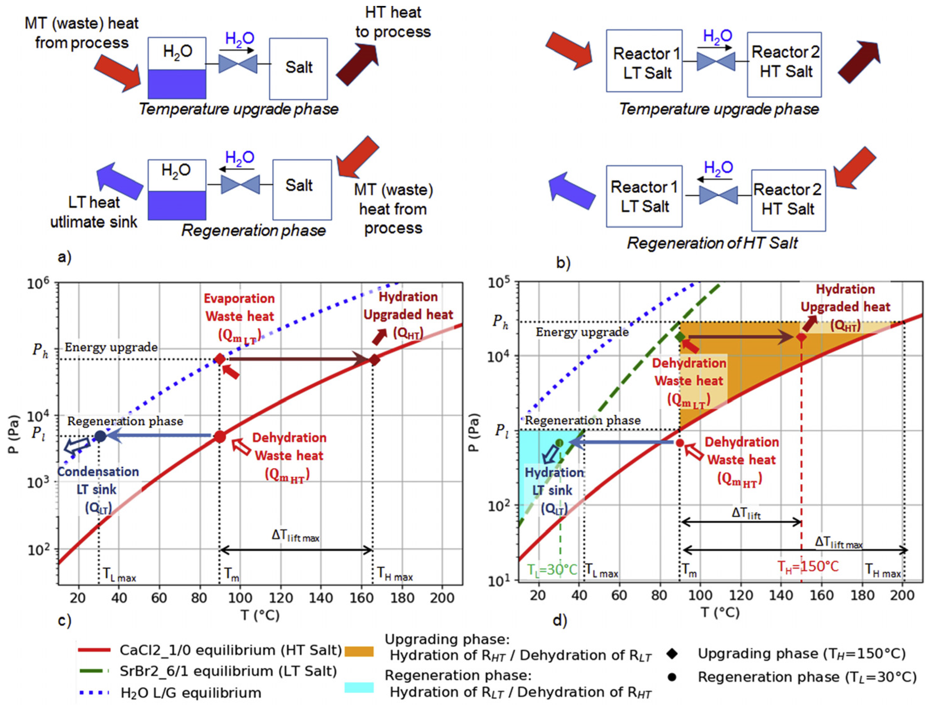
4.1. The 1-Salt and 2-Salt THT System

The most applied THT thermodynamic cycles are the single-stage 1-salt and 2-salt configurations [24,78]. The 2-salt THT system is also referred to as a thermochemical resorption heat transformer [79]. The differences between these configuration’s working principles using an example of CaCl2 and SrBr2 salt hydrate materials are shown in Figure 5 below.
Unlike the 1-salt THT system, which consists of one reactor and one heat exchanger (condenser/evaporator), in the 2-salt THT system, the heat exchanger is replaced by a second reactor containing a different TCM [24,79]. Most of the 2-salt THT systems found in the literature employ salt/ammonia working pairs, as an application of this 2-salt system will avoid the safety problem caused by the coexistence of high-pressure ammonia liquid and vapour at the same heat exchanger [24]. Even though the water vapour system does not possess the same safety problem as the ammonia system, applying the 2-salt system is beneficial to allow a broader range of operating conditions and achieve a higher temperature lift at reduced high-pressure lifts [78,79].
A screening method to select the best candidates of salt hydrate pairs for the 2-salt THT system were proposed by Michel and Clausse [78]. The proposed method consists of four criteria: comparison between source temperature and salt equilibrium temperature, Coefficient of Performance (COP), maximum thermal upgrade/temperature lift and driving forces. This method was applied to a representative case for waste heat recovery utilization, with a waste heat temperature of 90 °C, a target upgraded temperature of 150 °C, and a low-temperature source of 30 °C. Three promising salt hydrate pairs were identified from this screening work: CaCl2/Ca(NO3)2, CaCl2/SrBr2, and CaCl2/K(OH). Currently, the 2-salt THT system employing salt hydrate materials is still in the theoretical stage.

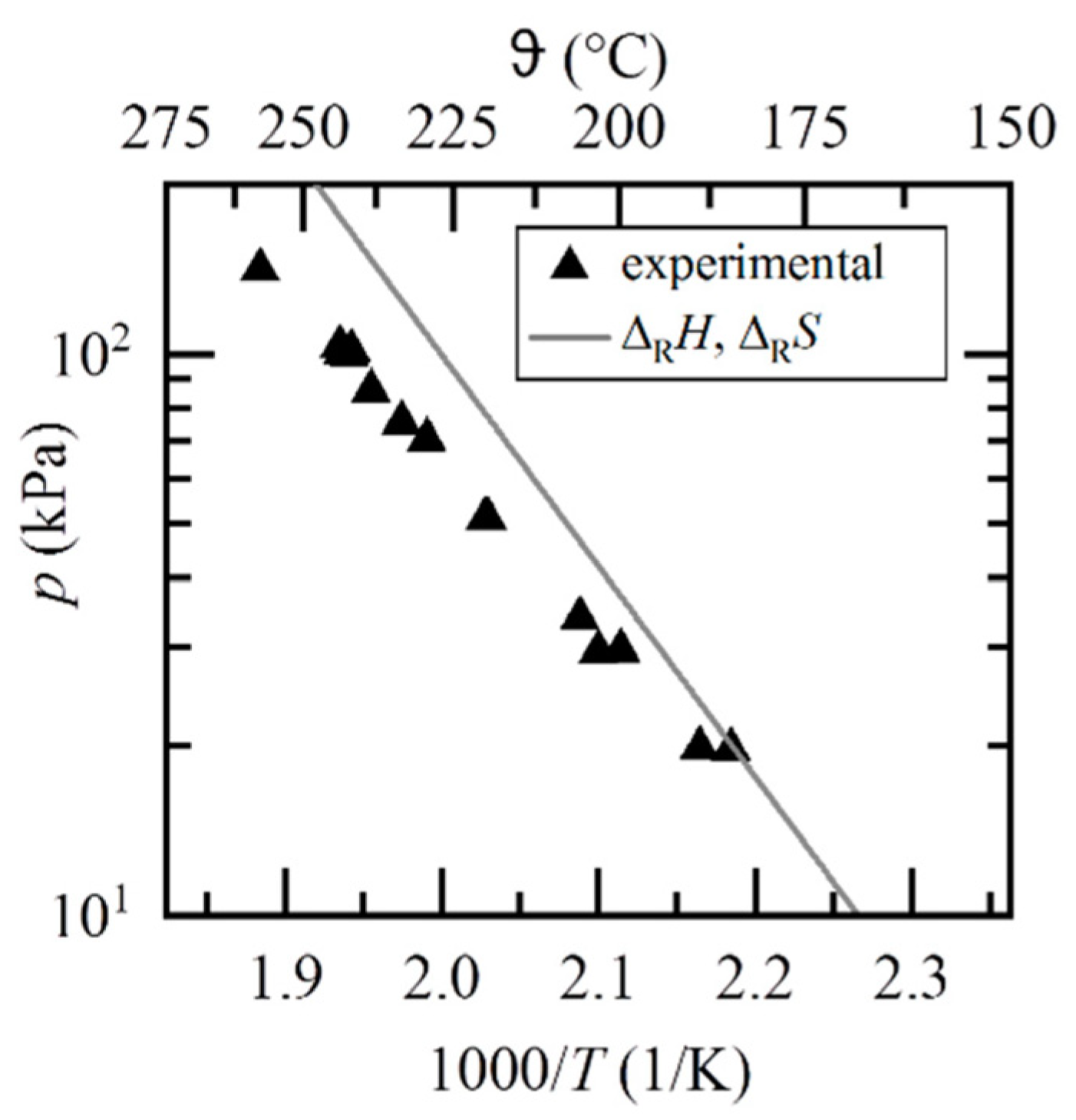
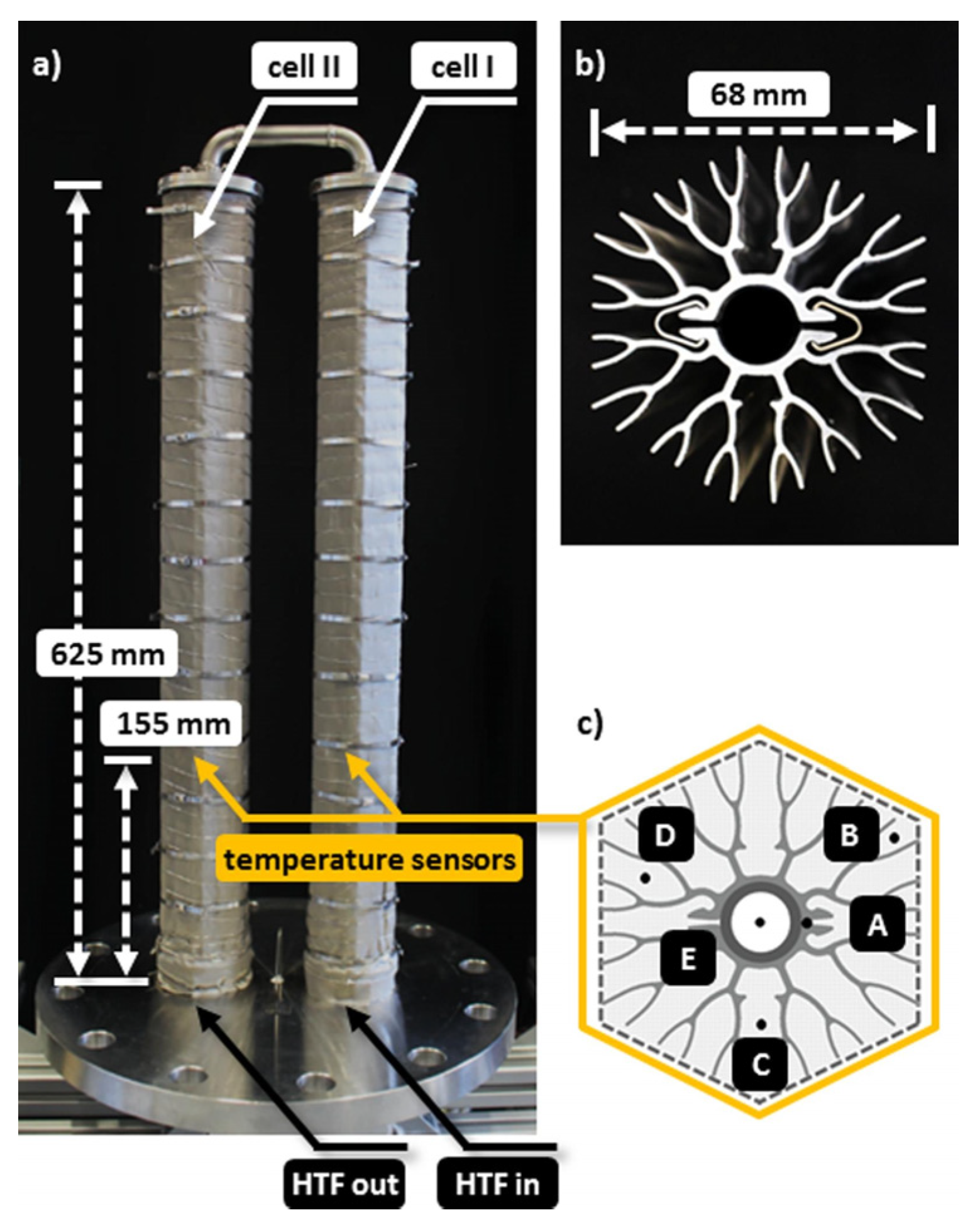
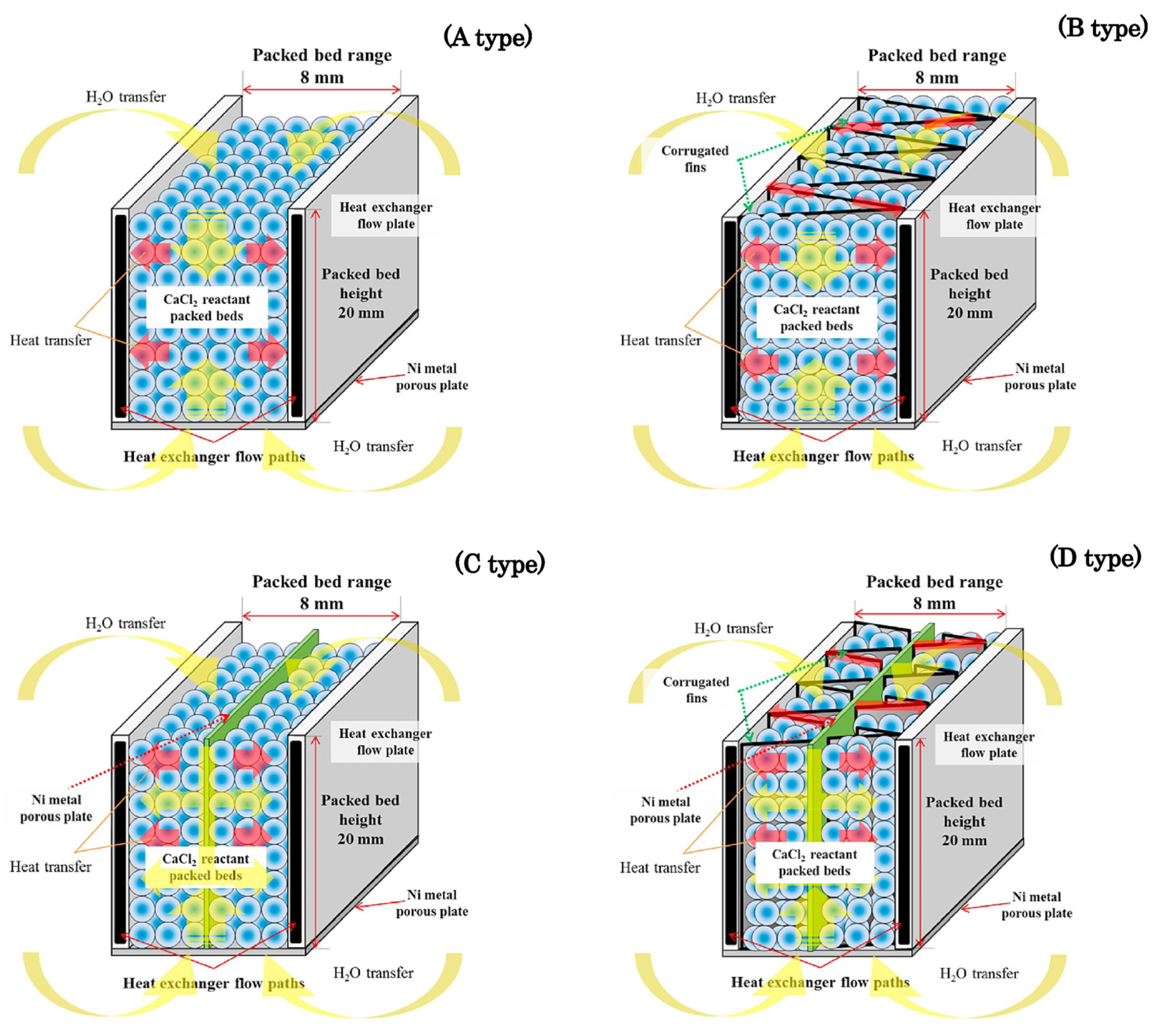
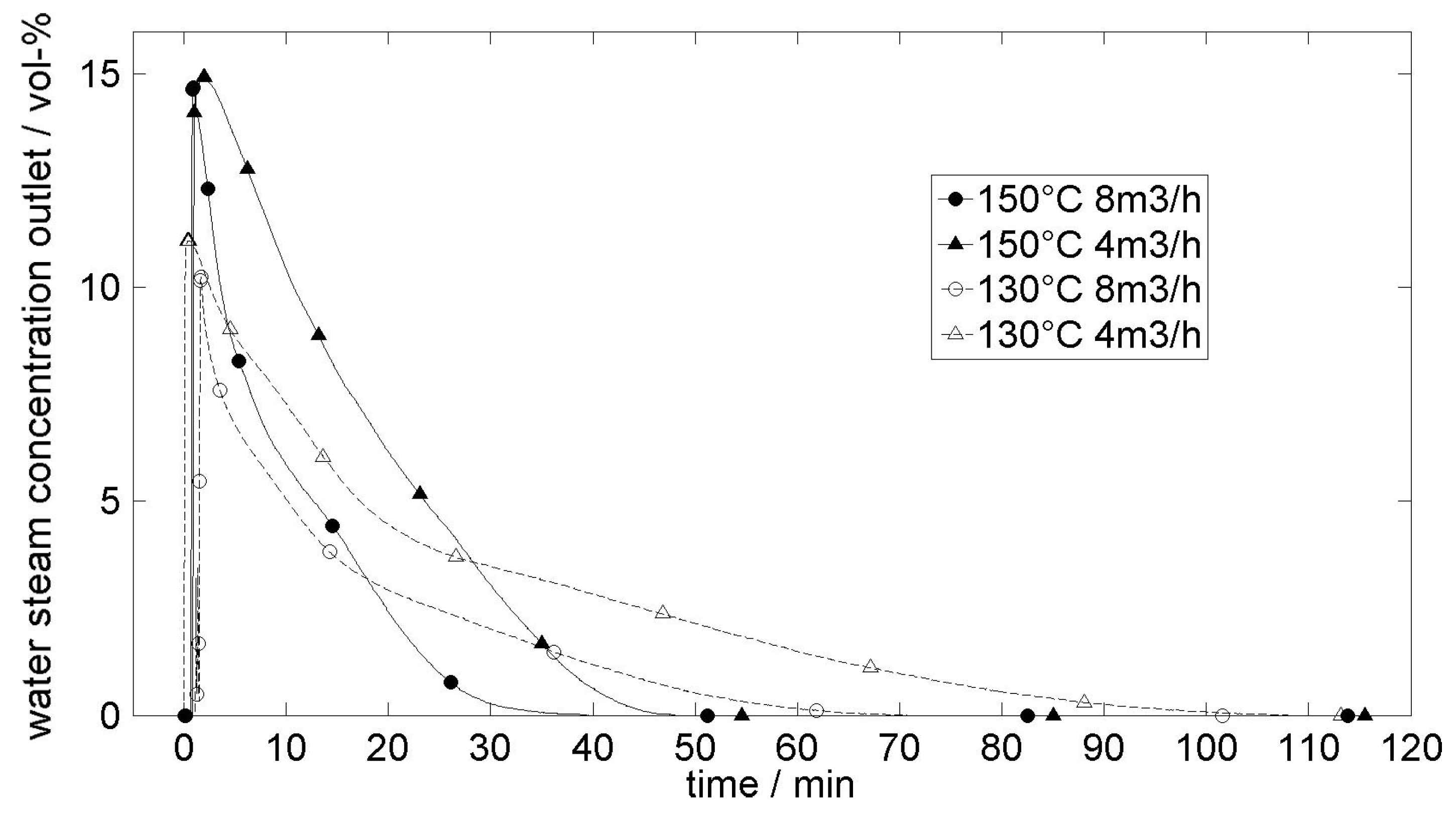
4.2. Salt Hydrate THT Experiments

Compared to salt hydrate TCES, salt hydrate THT experiments are in a far less advanced state. As shown in Table 2, only two salt hydrates tested for THT applications were found in the literature, which is SrBr2 [80,81,82,83] and CaCl2 [11,22,23,84]. All experiments of salt hydrate THT found in the literature are lab-scale 1-salt THT systems. The summary of publications on salt hydrate THT experiment and their key operating conditions and results is provided in Table 3.
Stengler et al. [80,81,83] conducted a THT experiment with SrBr2 salt hydrate material, based on the reversible reaction of SrBr2 monohydrate to the anhydrous SrBr2 as follows:
SrBr 2   ( s ) + H 2 O ( g )   SrBr 2 · H 2 O ( s ) + Δ R H
The experiment employed a lab-scale test reactor with a capacity of 1 kg material; the pillow-plates reactor design is shown in Figure 6. The TCM (SrBr2 powder) is filled to the space between two reactor plates. The experimental setup is a closed system; the reactor is connected to a tube bundle heat exchanger, acting as a condenser or evaporator during dehydration/hydration. Steam (water vapour) is flown through the reactor during the hydration reaction. Thermal oil (heat transfer fluid, HTF) is supplied to the surrounding of the reactor to provide heat during the dehydration reaction and to condition the reactor at a specific temperature during the hydration reaction. It was reported from this experiment that agglomeration of SrBr2 particles was observed after 11 cycles of dehydration and hydration [80].
By using the same reactor configuration, an experiment of variation of the evaporator (inlet water vapour) pressure and HTF temperature (initial reactor temperature) during the hydration/discharging phase was conducted [83]. The maximum reactor temperature recorded during hydration was plotted against the evaporator (inlet water vapour) pressure, as shown in Figure 7 below. The experimental data here is also compared with the correlation based on thermodynamic data. The highest maximum reactor temperature during hydration was 256 °C, obtained at an evaporator pressure of 144 kPa (=110 °C saturated water vapour temperature).
The cycle stability of the SrBr2 THT system was investigated in the subsequent experiment employing thermogravimetric analysis (TGA) [81]. A hundred (100) dehydration/hydration cycles were carried out; Figure 8 depicts the resulting reaction conversion from Cycle#1 to Cycle#100. The result shows stable cycles of SrBr2 transformation from monohydrate to anhydrous and vice versa, even though the reaction rate decelerates for both hydration and dehydration reactions. More significant deceleration was observed in the dehydration reaction.
A larger prototype of SrBr2 THT was developed by adapting a scalable reactor design [82]. The reactor module consists of two cells that hold 4.7 kg of SrBr2 material, as shown in Figure 9. This reactor is the biggest lab-scale THT prototype found in the literature. A cycling performance test was conducted on the reactor module with 34 dehydration/hydration cycles. From the test, it was concluded that no consistent decrease in total conversion or thermal power was identified. At the end of the cycling performance test, the TCM inside the reactor module were analyzed with scanning electron microscopy (SEM). Visually, it was seen that the bulk phase agglomerated into a single massive yet porous structure. However, according to the SEM result, the sintered solid structure is still a porous phase (not dense). Therefore, it was concluded that the overall porosity stays constant throughout the sintering process, with just the usual particle and void sizes altering.
Furthermore, a numerical model was developed to simulate and further investigate the performance characteristic of the scalable reactor module design with SrBr2 material [85]. The numerical model was based on the finite element method (FEM) in COMSOL Multiphysics® software. It was concluded from the numerical study that the boundary between the aluminium fins and the reactive bulk is the most significant constraint to the maximum thermal power of TES. Overall, the finned heat exchanger efficiently mitigates the TCM’s poor thermal conductivity; hence, an increase in bulk thermal conductivity would not influence the TES’s overall performance.
Another salt hydrate that has been experimented with for THT application is CaCl2 which undergoes the following reaction:
CaCl 2   ( s ) + 2 H 2 O ( g )   CaCl 2 · 2 H 2 O ( s ) + Δ R H
A closed system test bench was developed by Richter et al. [11], with approximately 0.7 kg CaCl2 contained inside the reactor. The HTF flows through the reactor’s shell, tempering the reaction bed through a thermostatic bath. It was noted from this experiment that a hydration temperature lower than 160 °C results in the deliquescence of the hydrate. Two reaction steps were observed during dehydration (dihydrate to monohydrate and monohydrate to anhydrous). While during hydration, three reaction steps were observed (anhydrous to CaCl2·0.3H2O, CaCl2·0.3H2O to monohydrate, and monohydrate to dihydrate). The most significant temperature lift is observed during the hydration reaction’s first step, as shown in Figure 10.
After several cycles, it was observed in this experiment that the salt particles agglomerate into highly porous structures, and the channels are formed inside reactor tubes. It was concluded from the investigation that due to the several stages of reactions and deliquescence; the reaction system CaCl2/H2O is not optimum. However, it is adequate reference information for demonstrating and understanding the technique’s limits. It was concluded from this experiment.
Another closed system experiment of CaCl2 for THT application was conducted by Esaki et al. [23]. Four types of reactor modules were employed in this experiment; the schematic of reactors modules is shown in Figure 11. Approximately 0.5 kg of CaCl2 material is contained in each reactor. A thermostatic bath containing HTF is connected to the reactor to adjust its initial temperature during reactions. The maximum outlet temperature recorded during discharging phase is 158.4–162 °C, and the author stated a significant thermal upgrade obtained from the charging temperature of 100 °C. However, it was mentioned in the paper that the inlet temperature of HTF (reactor module fluid) was set at 155 °C during discharging phase. It means that the thermal upgrade is only 3.4–7 °C if the initial reactor temperature is used as the reference temperature.
An experiment designed to compare the thermal upgrade performance of packed-bed reactor design and coated reactor/heat exchanger design with CaCl2 material was conducted by Michel et al. [84]. Polyvinyl alcohol (PVA) was used as the binder material to coat CaCl2 to the reactor wall (1–2 cm of coating thickness). Only the hydration phase was conducted in this work; the experiment result is shown in Figure 12. A thermal upgrade of 60 °C and 63 °C is claimed in this work by using water evaporation temperature during the hydration phase as the reference temperature. The coated reactor design achieved a significantly higher specific power (341 W/kg) than the packed-bed reactor design (180 W/kg). However, coating deterioration (cracks and loss of adhesion) was observed during cyclability testing, which decreased its performance.
The only open system experiment of salt hydrate THT in the literature was conducted by Bouché et al. [22]. However, the full cycle (dehydration and hydration) was not done in this work (only the dehydration phase was done); thus, the resulting thermal upgrade from this open system cannot be concluded. The reactor is designed as a bundle tube exchanger; approximately 0.63 kg of CaCl2 material is placed evenly in the tubes. Since it is an open system, the reactor was not connected to a condenser or evaporator. A thermostatic bath containing HTF is connected to the reactor’s shell side to provide heat during the dehydration reaction. The electric preheater heats the air to a charging temperature before passing it to the reactor to commence the dehydration process. Water vapour is emitted from the salt hydrate as a result of the dehydration process, raising the partial vapour pressure in the air. Gas analyzers are installed at the reactor’s inlet and exit to measure water vapour concentration, which will then be used to calculate the reaction conversion.
This open system THT tested a variation of reactor design (with and without gas channels), air flow rate, and charging temperature. It was concluded from the experiment that the dehydration reaction occurs faster at a higher air flow rate and charging temperature. Figure 13 shows the effect of air flow rate and charging temperature on the peak water vapour concentration and the reaction time.

4.3. Alternative Material and Application

In addition to the heat transformer system, steam generation is another application used to obtain a thermal upgrade. The difference between heat transformer and steam generation application lies in the phase of water fed to the inlet reactor during the discharging phase. In heat transformer application, the input fluid to the reactor during the hydration reaction is in a vapour phase. The water vapour/humid air enters the reactor at a lower temperature and exits the reactor at a higher temperature. Meanwhile, in steam generation applications, the input fluid to the reactor during the adsorption/hydration reaction is in the liquid phase. The liquid water enters the reactor at a lower temperature and exits the reactor as steam (vapour phase) at a higher temperature. It means that in steam generation applications, the heat of adsorption/reaction provides both temperature upgrades and energy required for water evaporation. Hence most of the heat generated will be utilized to evaporate the water rather than creating temperature lift.
The adsorption materials (e.g., zeolite, silica gel, activated alumina) have been experimented with both heat transformer and steam generation applications. The adsorption material is classified as Sorption/Chemical TES under the sub-category of physisorption, which is a different sub-category to thermochemical [16,29]. The heat of adsorption in physisorption is lower than in chemisorption [86]. The heat transformer application employing adsorption materials is referred to as Adsorption Heat Transformer (AHT or AdHT) [87,88]. A recent AHT experiment reported a thermal upgrade of 20 °C was achieved for a silica gel-water vapour closed system [88]. A theoretical work analyzing the thermodynamic performance of multiple adsorption working pairs was performed by Frazzica et al. [89], including silica gel/water vapour, AQSOA Zeolite/water vapour, MWCNT-LiCl/water vapour, and silica gel-LiCl/water vapour. This work reported that a higher sorption capacity was achieved by composite sorbents (LiCl salt embedded in adsorbent material). A temperature lift of 50 °C was predicted for silica gel-LiCl composite from the waste heat temperature of 80 °C. Therefore, the composite material was viewed as a better material compared to pure adsorbent for heat transformer applications [89].
The experimental investigation of these salt hydrate/adsorption composite materials has not yet been done for heat transformer application, but it has been experimented with steam generation application. Xue et al. [90] investigated the effect of CaCl2 addition to zeolite for steam generation applications and compared its performance with pure zeolite. The experiment applied an open system concept; the setup is shown in Figure 14. During the generation (adsorption/hydration) process, liquid water at 80 °C is supplied to the bottom of the reactor. The generated steam was collected from the top of the reactor, condensed and weighed. The generation process is stopped when water fills the reactor, and the temperature at the top of the reactor is equal to the inlet water temperature. During the regeneration (desorption/dehydration) process, dry air at 130 °C is flown from the top of the reactor and released into the atmosphere from the bottom. The regeneration process is stopped when the temperature at the bottom of the reactor is equal to the inlet hot air temperature.
This experiment analyzed three materials: pure zeolite, a composite of zeolite with 20% CaCl2, and a composite of zeolite with 40% CaCl2. The zeolite/CaCl2 composite materials were prepared with ion-exchange and re-impregnation methods and characterized with SEM, X-ray Fluorescence (XRF), and Brunauer-Emmet-Teller (BET) model. The experiment concluded that the composite materials achieved the same thermal upgrade as the pure zeolite during generation. The generated steam temperature in this experiment was 210 °C, which is higher than the steam generation experiment with pure zeolite conducted by Oktariani et al. [91], whereby the steam is generated at 150 °C from the feed water at 80 °C. Even though the addition of salt hydrate did not increase the thermal upgrade performance, it improved the “effective time ratio” (the ratio of time spent on steam generation to time spent on the entire generation process) by 18.6% and increased the mass of generated steam by 12.9% compared to pure zeolite. It was observed in the subsequent experiment [92] that the total mass of the CaCl2/Zeolite composite material reduced to 65% of the initial mass after five cycles. It was caused by the effusion of CaCl2 from zeolite pores during contact with liquid water. Therefore, Zhang et al. [93] conducted a follow-up experiment to replace CaCl2 with MgSO4 (non-hygroscopic salt).
The above steam generation experiment confirmed the positive impact of salt hydrate incorporation into the pure adsorbent. Moreover, it shows that the open system set-up with the composite material was capable of generating superheated steam from the inlet water at 80 °C.

5. Research Gaps, Challenges, and Opportunities

The results from existing experiments on THT and steam generation applications have shown that salt hydrate material has a good thermal upgrade potential. However, the utilization of salt hydrate as TCM for THT applications is currently still limited. Only two salt hydrates have been experimented with: CaCl2 and SrBr2 in a single pure salt hydrate form. Experiments on the combination/mixture of salt hydrates, a composite of salt hydrate and porous matrix, or salt hydrate composite with additive materials for THT applications have not been reported. Thus, the limitation of experimented salt hydrate material for THT application is the first research gap identified in this review.
The second identified research gap from this review is the lack of open-system salt hydrate THT implementation. The majority of existing salt hydrate THT experiments employed a pressurized closed system. It means that the advantage of non-toxicity of the salt hydrate/water vapour working pairs, which allows implementation of a less-costly open system as it can be immediately discharged to the environment, has not been fully exploited. Furthermore, the reactor design implemented in these experiments is a fixed-bed reactor. Other designs, such as moving and fluidized beds, could improve the heat and mass transfer, which are always limiting in any TCM system [17].
Finding the most suitable salt hydrate material and reactor/system design are the main challenges at the current stage. The material/system design shall achieve an adequate and consistent thermal upgrade for application in industrial waste heat recovery. It must also show a reliable cyclability performance to keep up with the continuous industrial process. A further challenge is confirming salt hydrate THT’s economic competitiveness and environmental benefit compared to the existing heat recovery technologies. A preliminary techno-economic analysis and a screening level Life Cycle Assessment (LCA) could be employed for this purpose, which is limited even for TCES applications [94].
The above-identified research gaps and challenges from this review indicate that salt hydrate THT is still in the early stage of research, which presents an opportunity to advance the research further to achieve a higher Technology Readiness Level (TRL). Currently, all experiments of salt hydrate THT found in the literature are on a lab scale and at a smaller capacity than the salt hydrate TCES prototype. The biggest salt hydrate THT reactor capacity is 4.7 kg of SrBr2 [82]. Meanwhile, some TCES prototypes have achieved a considerably larger capacity, for example, a packed bed reactor containing 400 kg SrBr2 material developed by Michel et al. [45]. This fact suggests that salt hydrate THT research lags significantly behind TCES research and needs to catch up.
The problem of energy shortage and global warming has become a pressing global issue that will continue to push the recovery of low-temperature industrial waste heat. A successful application of salt hydrate THT will allow the recovery of low-temperature industrial waste heat. It will significantly reduce energy consumption, increase overall energy efficiency, improve economic benefits, and reduce GHG emissions from the industrial sector. Moreover, compared to other recovery technologies, THT has the advantage of an energy storage function that will prevent thermal pollution caused by industrial waste rejection to the environment during high supply. With THT application, the excess waste heat can be stored for an unlimited time and reproduced during high demand.

6. Conclusions

One of the key areas for enhancing energy efficiency and lowering GHG emissions is the development of innovative industrial waste heat recovery technologies. This review provides an overview of the potential of salt hydrate THT for the recovery of low-temperature industrial waste heat and the recent research advancement of this emerging technology. THT is differentiated from the TCES application based on the charging/discharging temperature level. In TCES, the stored energy is released at a lower discharging temperature than its charging temperature. The purpose of the TCES system is mainly to provide heating/cooling or domestic hot water for buildings (discharging temperature of <65 °C). Meanwhile, in the THT application, the stored energy is discharged at a higher temperature than its charging temperature or temperature useful for industrial heat (>100 °C)
The literature demonstrates that the salt hydrate THT is significantly less developed than the TCES. The amount of experimental, theoretical, numerical, and modelling work done for the salt hydrate THT system is substantially limited. There is a huge room for improvement in this research area which should be a focus for future research work, including developing novel salt hydrate composite material specifically for high-temperature applications, designing a reactor and THT system with a focus on recovering industrial waste heat, conducting numerical studies on salt hydrate THT system design, and assessing its economic competitiveness and environmental performance.

Author Contributions

The literature research and initial manuscript writing were done by I.H. Supervision, and advice and editing were carried out by A.A. and M.F. All authors have read and agreed to the published version of the manuscript.

Funding

This research was supported by the University of Auckland Doctoral Scholarship. Author 2 and the corresponding author confirm the accuracy of the funding data.

Data Availability Statement

Data sharing is not applicable.

Acknowledgments

Isye Hayatina thanks the University of Auckland for providing her with a Doctoral Scholarship. Amar Auckaili and Mohammed Farid consent to this acknowledgement.

Conflicts of Interest

The authors declare no conflict of interest.

Nomenclature

ACActivated carbon
BETBrunauer-Emmet-Teller
BTUBritish thermal unit
CNFCellulose nanofibrils
COPCoefficient of performance
EECAEnergy Efficiency and Conservation Authority
EIAEnergy Information Administration
ENGExpanded natural graphite
ENG TSAExpanded Natural Graphite Treated with Sulfuric Acid
EUEuropean Union
GHGGreenhouse gas
GTLGross temperature lift
HTFHeat transfer fluid
IPCCIntergovernmental Panel on climate change
LNGLiquefied natural gas
MVCMechanical vapour compression
MVRMechanical vapour recompression
MWCNTMulti-wall carbon nanotubes
PDACPolydiallyldimethylammonium chloride
PVAPolyvynyl alcohol
SEMScanning electron microscopy
STASimultaneous thermal analysis
TCESThermochemical energy storage
TCHSThermochemical heat storage
THTThermochemical heat transformer
TCMThermochemical material
TESThermal energy storage
TGAThermogravimetric analysis
TRLTechnology Readiness Level
XRFX-ray Fluorescence
ZMSZeolite molecular sieve

References

  1. US EIA. International Energy Outlook 2021; US EIA: Washington, DA, USA, 2021. Available online: https://www.eia.gov/outlooks/ieo/tables_side_xls.php (accessed on 24 January 2023).
  2. Johnson, I.; Choate, W.T.; Davidson, A. Waste Heat Recovery: Technology and Opportunities in US Industry; U.S. Department of Energy: Washington, DA, USA, 2008. Available online: https://www.osti.gov/biblio/1218716 (accessed on 16 January 2023).
  3. Brueckner, S.; Miró, L.; Cabeza, L.F.; Pehnt, M.; Laevemann, E. Methods to Estimate the Industrial Waste Heat Potential of Regions—A Categorization and Literature Review. Renew. Sustain. Energy Rev. 2014, 38, 164–171. [Google Scholar] [CrossRef]
  4. Miró, L.; Brückner, S.; Cabeza, L.F. Mapping and Discussing Industrial Waste Heat (IWH) Potentials for Different Countries. Renew. Sustain. Energy Rev. 2015, 51, 847–855. [Google Scholar] [CrossRef] [Green Version]
  5. McKenna, R.C.; Norman, J.B. Spatial Modelling of Industrial Heat Loads and Recovery Potentials in the UK. Energy Policy 2010, 38, 5878–5891. [Google Scholar] [CrossRef]
  6. Brueckner, S.; Arbter, R.; Pehnt, M.; Laevemann, E. Industrial Waste Heat Potential in Germany—A Bottom-up Analysis. Energy Effic. 2017, 10, 513–525. [Google Scholar] [CrossRef]
  7. Hong, G.B.; Pan, T.C.; Chan, D.Y.L.; Liu, I.H. Bottom-up Analysis of Industrial Waste Heat Potential in Taiwan. Energy 2020, 198, 117393. [Google Scholar] [CrossRef]
  8. Papapetrou, M.; Kosmadakis, G.; Cipollina, A.; La Commare, U.; Micale, G. Industrial Waste Heat: Estimation of the Technically Available Resource in the EU per Industrial Sector, Temperature Level and Country. Appl. Therm. Eng. 2018, 138, 207–216. [Google Scholar] [CrossRef]
  9. Blesl, M.; Kempe, S.; Ohl, M.; Fahl, U.; König, A.; Jenssen, T.; Eltrop, L. Wärmeatlas Baden-Württemberg—Erstellung Eines Leitfadens und Umsetzung für Modellregionen (Heat Atlas Baden-Württemberg—Creation of a Guide and Implementation for Model Regions); University of Stuttgart: Stuttgart, Germany, 2009. [Google Scholar]
  10. Blesl, M.; Ohl, M.; Fahl, U. Ganzheitliche Bewertung Innovativer Mobiler Thermischer Energiespeicherkonzepte für Baden-Württemberg auf Basis Branchen- und Betriebsspezifischer Wärmebedarfsstrukturen (Holistic Assessment of Innovative Mobile Thermal Energy Storage Concepts for Baden-Württemberg Based on Industry and Company-Specific Heat Demand Structures); University of Stuttgart: Stuttgart, Germany, 2011. [Google Scholar]
  11. Richter, M.; Bouché, M.; Linder, M. Heat Transformation Based on CaCl2/H2O—Part A: Closed Operation Principle. Appl. Therm. Eng. 2016, 102, 615–621. [Google Scholar] [CrossRef] [Green Version]
  12. Su, Z.; Zhang, M.; Xu, P.; Zhao, Z.; Wang, Z.; Huang, H.; Ouyang, T. Opportunities and Strategies for Multigrade Waste Heat Utilization in Various Industries: A Recent Review. Energy Convers. Manag. 2021, 229, 113769. [Google Scholar] [CrossRef]
  13. Hung, T.C.; Shai, T.Y.; Wang, S.K. A Review of Organic Rankine Cycles (ORCs) for The Recovery of Low-Grade Waste Heat. Energy 1997, 22, 661–667. [Google Scholar] [CrossRef]
  14. Kishore, R.A.; Priya, S. A Review on Low-Grade Thermal Energy Harvesting: Materials, Methods and Devices. Materials 2018, 11, 1433. [Google Scholar] [CrossRef] [PubMed] [Green Version]
  15. Dinçer, İ.; Rosen, M.A. Thermal Energy Storage and Energy Savings. In Thermal Energy Storage; John Wiley & Sons, Ltd.: Hoboken, NJ, USA, 2010; pp. 211–231. [Google Scholar]
  16. N’Tsoukpoe, K.E.; Osterland, T.; Opel, O.; Ruck, W.K.L. Cascade Thermochemical Storage with Internal Condensation Heat Recovery for Better Energy and Exergy Efficiencies. Appl. Energy 2016, 181, 562–574. [Google Scholar] [CrossRef]
  17. Solé, A.; Martorell, I.; Cabeza, L.F. State of the Art on Gas-Solid Thermochemical Energy Storage Systems and Reactors for Building Applications. Renew. Sustain. Energy Rev. 2015, 47, 386–398. [Google Scholar] [CrossRef] [Green Version]
  18. Stutz, B.; Le Pierres, N.; Kuznik, F.; Johannes, K.; Palomo Del Barrio, E.; Bédécarrats, J.P.; Gibout, S.; Marty, P.; Zalewski, L.; Soto, J.; et al. Storage of Thermal Solar Energy. Comptes Rendus Phys. 2017, 18, 401–414. [Google Scholar] [CrossRef]
  19. Farid, M.; Khudhair, A.M.; Razack, S.A.K.; Al-Hallaj, S. A Review on Phase Change Energy Storage Materials and Applications. In Thermal Energy Storage with Phase Change Materials; Farid, M., Auckaili, A., Gholamibozanjani, G., Eds.; Taylor & Francis: Abingdon, UK, 2021; pp. 4–23. [Google Scholar]
  20. Schmerse, E.; Ikutegbe, C.A.; Auckaili, A.; Farid, M.M. Using Pcm in Two Proposed Residential Buildings in Christchurch, New Zealand. Energy 2020, 13, 6025. [Google Scholar] [CrossRef]
  21. N’Tsoukpoe, K.E.; Schmidt, T.; Rammelberg, H.U.; Watts, B.A.; Ruck, W.K.L. A Systematic Multi-Step Screening of Numerous Salt Hydrates for Low Temperature Thermochemical Energy Storage. Appl. Energy 2014, 124, 1–16. [Google Scholar] [CrossRef]
  22. Bouché, M.; Richter, M.; Linder, M. Heat Transformation Based on CaCl2/H2O—Part B: Open Operation Principle. Appl. Therm. Eng. 2016, 102, 641–647. [Google Scholar] [CrossRef] [Green Version]
  23. Esaki, T.; Yasuda, M.; Kobayashi, N. Experimental Evaluation of the Heat Output/Input and Coefficient of Performance Characteristics of a Chemical Heat Pump in the Heat Upgrading Cycle of CaCl2 Hydration. Energy Convers. Manag. 2017, 150, 365–374. [Google Scholar] [CrossRef]
  24. Yu, Y.Q.; Zhang, P.; Wu, J.Y.; Wang, R.Z. Energy Upgrading by Solid-Gas Reaction Heat Transformer: A Critical Review. Renew. Sustain. Energy Rev. 2008, 12, 1302–1324. [Google Scholar] [CrossRef]
  25. Wongsuwan, W.; Kumar, S.; Neveu, P.; Meunier, F. A Review of Chemical Heat Pump Technology and Applications. Appl. Therm. Eng. 2001, 21, 1489–1519. [Google Scholar] [CrossRef]
  26. Fadhel, M.I.; Sopian, K.; Daud, W.R.W.; Alghoul, M.A. Review on Advanced of Solar Assisted Chemical Heat Pump Dryer for Agriculture Produce. Renew. Sustain. Energy Rev. 2011, 15, 1152–1168. [Google Scholar] [CrossRef]
  27. Cot-Gores, J.; Castell, A.; Cabeza, L.F. Thermochemical Energy Storage and Conversion: A-State-of-the-Art Review of the Experimental Research under Practical Conditions. Renew. Sustain. Energy Rev. 2012, 16, 5207–5224. [Google Scholar] [CrossRef]
  28. Chan, C.W.; Ling-Chin, J.; Roskilly, A.P. A Review of Chemical Heat Pumps, Thermodynamic Cycles and Thermal Energy Storage Technologies for Low Grade Heat Utilisation. In Applied Thermal Engineering; Elsevier: Amsterdam, The Netherlands, 2013; Volume 50, pp. 1257–1273. [Google Scholar]
  29. N’Tsoukpoe, K.E.; Liu, H.; Le Pierrès, N.; Luo, L. A Review on Long-Term Sorption Solar Energy Storage. Renew. Sustain. Energy Rev. 2009, 13, 2385–2396. [Google Scholar] [CrossRef]
  30. Clark, R.J.; Farid, M. Experimental Investigation into the Performance of Novel SrCl2-Based Composite Material for Thermochemical Energy Storage. J. Energy Storage 2021, 36, 102390. [Google Scholar] [CrossRef]
  31. Park, D.; Hayatina, I.; Farid, M.; Auckaili, A. Experimental Work on Salt-Based Cooling Systems. Thermo 2023, 3, 200–215. [Google Scholar] [CrossRef]
  32. Ferrucci, F.; Stitou, D.; Ortega, P.; Lucas, F. Mechanical Compressor-Driven Thermochemical Storage for Cooling Applications in Tropical Insular Regions. Concept and Efficiency Analysis. Appl. Energy 2018, 219, 240–255. [Google Scholar] [CrossRef]
  33. Fitó, J.; Coronas, A.; Mauran, S.; Mazet, N.; Perier-Muzet, M.; Stitou, D. Hybrid System Combining Mechanical Compression and Thermochemical Storage of Ammonia Vapor for Cold Production. Energy Convers. Manag. 2019, 180, 709–723. [Google Scholar] [CrossRef]
  34. Park, J.-G.; Han, S.-C.; Jang, H.-Y.; Lee, S.-M.; Lee, P.S.; Lee, J.-Y. The Development of Compressor-Driven Metal Hydride Heat Pump (CDMHHP) System as an Air Conditioner. Int. J. Hydrogen Energy 2002, 27, 941–944. [Google Scholar] [CrossRef]
  35. Desai, F.; Atayo, A.; Prasad, J.S.; Muthukumar, P.; Rahman, M.; Asmatulu, E. Experimental Studies on Endothermic Reversible Reaction of Salts for Cooling. Heat Transf. Eng. 2021, 42, 1107–1116. [Google Scholar] [CrossRef]
  36. Li, T.X.; Wang, R.Z.; Yan, T. Solid-Gas Thermochemical Sorption Thermal Battery for Solar Cooling and Heating Energy Storage and Heat Transformer. Energy 2015, 84, 745–758. [Google Scholar] [CrossRef]
  37. Clark, R.J.; Mehrabadi, A.; Farid, M. State of the Art on Salt Hydrate Thermochemical Energy Storage Systems for Use in Building Applications. J. Energy Storage 2020, 27, 101145. [Google Scholar] [CrossRef]
  38. Spinner, B. Ammonia-Based Thermochemical Transformers. Heat Recovery Syst. CHP 1993, 13, 301–307. [Google Scholar] [CrossRef]
  39. Stitou, D.; Mazet, N.; Bonnissel, M. Performance of a High Temperature Hydrate Solid/Gas Sorption Heat Pump Used as Topping Cycle for Cascaded Sorption Chillers. Energy 2004, 29, 267–285. [Google Scholar] [CrossRef]
  40. Scapino, L.; Zondag, H.A.; Van Bael, J.; Diriken, J.; Rindt, C.C.M. Sorption Heat Storage for Long-Term Low-Temperature Applications: A Review on the Advancements at Material and Prototype Scale. Appl. Energy 2017, 190, 920–948. [Google Scholar] [CrossRef]
  41. Zhang, Y.N.; Wang, R.Z.; Li, T.X. Experimental Investigation on an Open Sorption Thermal Storage System for Space Heating. Energy 2017, 141, 2421–2433. [Google Scholar] [CrossRef]
  42. De Boer, R.; Haije, W.G.; Veldhuis, J.B.J.; Smeding, S.F. Solid-Sorption Cooling with Integrated Thermal Storage: The SWEAT Prototype. In Proceedings of the International Conference of Heat Powered Cycles, Larnaca, Cyprus, 11–13 October 2004. [Google Scholar]
  43. Zondag, H.; Kikkert, B.; Smeding, S.; de Boer, R.; Bakker, M. Prototype Thermochemical Heat Storage with Open Reactor System. Appl. Energy 2013, 109, 360–365. [Google Scholar] [CrossRef]
  44. Linnow, K.; Niermann, M.; Bonatz, D.; Posern, K.; Steiger, M. Experimental Studies of the Mechanism and Kinetics of Hydration Reactions. In Energy Procedia; Elsevier Ltd.: Amsterdam, The Netherlands, 2014; Volume 48, pp. 394–404. [Google Scholar]
  45. Michel, B.; Mazet, N.; Neveu, P. Experimental Investigation of an Innovative Thermochemical Process Operating with a Hydrate Salt and Moist Air for Thermal Storage of Solar Energy: Global Performance. Appl. Energy 2014, 129, 177–186. [Google Scholar] [CrossRef] [Green Version]
  46. Korhammer, K.; Druske, M.M.; Fopah-Lele, A.; Rammelberg, H.U.; Wegscheider, N.; Opel, O.; Osterland, T.; Ruck, W. Sorption and Thermal Characterization of Composite Materials Based on Chlorides for Thermal Energy Storage. Appl. Energy 2016, 162, 1462–1472. [Google Scholar] [CrossRef]
  47. Li, S.; Huang, H.; Yang, X.; Bai, Y.; Li, J.; Kobayashi, N.; Kubota, M. Hydrophilic Substance Assisted Low Temperature LiOH·H2O Based Composite Thermochemical Materials for Thermal Energy Storage. Appl. Therm. Eng. 2018, 128, 706–711. [Google Scholar] [CrossRef]
  48. Rammelberg, H.U.; Osterland, T.; Priehs, B.; Opel, O.; Ruck, W.K.L. Thermochemical Heat Storage Materials—Performance of Mixed Salt Hydrates. Sol. Energy 2016, 136, 571–589. [Google Scholar] [CrossRef]
  49. Rehman, A.U.; Khan, M.; Maosheng, Z. Hydration Behavior of MgSO4–ZnSO4 Composites for Long-Term Thermochemical Heat Storage Application. J. Energy Storage 2019, 26, 101026. [Google Scholar] [CrossRef]
  50. Li, W.; Zeng, M.; Wang, Q. Development and Performance Investigation of MgSO4/SrCl2 Composite Salt Hydrate for Mid-Low Temperature Thermochemical Heat Storage. Sol. Energy Mater. Sol. Cells 2020, 210, 110509. [Google Scholar] [CrossRef]
  51. Ousaleh, H.A.; Said, S.; Zaki, A.; Faik, A.; El Bouari, A. Silica Gel/Inorganic Salts Composites for Thermochemical Heat Storage: Improvement of Energy Storage Density and Assessment of Cycling Stability. In Materials Today: Proceedings; Elsevier Ltd.: Amsterdam, The Netherlands, 2019; Volume 30, pp. 937–941. [Google Scholar]
  52. Jabbari-Hichri, A.; Bennici, S.; Auroux, A. Enhancing the Heat Storage Density of Silica–Alumina by Addition of Hygroscopic Salts (CaCl2, Ba(OH)2, and LiNO3). Sol. Energy Mater. Sol. Cells 2015, 140, 351–360. [Google Scholar] [CrossRef]
  53. Casey, S.P.; Elvins, J.; Riffat, S.; Robinson, A. Salt Impregnated Desiccant Matrices for “open” Thermochemical Energy Storage—Selection, Synthesis and Characterisation of Candidate Materials. Energy Build. 2014, 84, 412–425. [Google Scholar] [CrossRef]
  54. Shkatulov, A.I.; Houben, J.; Fischer, H.; Huinink, H.P. Stabilization of K2CO3 in Vermiculite for Thermochemical Energy Storage. Renew. Energy 2020, 150, 990–1000. [Google Scholar] [CrossRef]
  55. Xu, J.X.; Li, T.X.; Chao, J.W.; Yan, T.S.; Wang, R.Z. High Energy-Density Multi-Form Thermochemical Energy Storage Based on Multi-Step Sorption Processes. Energy 2019, 185, 1131–1142. [Google Scholar] [CrossRef]
  56. Whiting, G.; Grondin, D.; Bennici, S.; Auroux, A. Heats of Water Sorption Studies on Zeolite-MgSO4 Composites as Potential Thermochemical Heat Storage Materials. Sol. Energy Mater. Sol. Cells 2013, 112, 112–119. [Google Scholar] [CrossRef]
  57. Clark, R.J.; Farid, M. Experimental Investigation into Cascade Thermochemical Energy Storage System Using SrCl2-Cement and Zeolite-13X Materials. Appl. Energy 2022, 316, 119145. [Google Scholar] [CrossRef]
  58. Mauran, S.; Lahmidi, H.; Goetz, V. Solar Heating and Cooling by a Thermochemical Process. First Experiments of a Prototype Storing 60 KW h by a Solid/Gas Reaction. Sol. Energy 2008, 82, 623–636. [Google Scholar] [CrossRef]
  59. Li, W.; Klemeš, J.J.; Wang, Q.; Zeng, M. Characterisation and Sorption Behaviour of LiOH-LiCl@EG Composite Sorbents for Thermochemical Energy Storage with Controllable Thermal Upgradeability. Chem. Eng. J. 2021, 421, 129586. [Google Scholar] [CrossRef]
  60. Xueling, Z.; Feifei, W.; Qi, Z.; Xudong, L.; Yanling, W.; Yeqiang, Z.; Chuanxiao, C.; Tingxiang, J. Heat Storage Performance Analysis of ZMS-Porous Media/CaCl2/MgSO4 Composite Thermochemical Heat Storage Materials. Sol. Energy Mater. Sol. Cells 2021, 230, 111246. [Google Scholar] [CrossRef]
  61. Yu, N.; Wang, R.Z.; Lu, Z.S.; Wang, L.W. Study on Consolidated Composite Sorbents Impregnated with LiCl for Thermal Energy Storage. Int. J. Heat Mass Transf. 2015, 84, 660–670. [Google Scholar] [CrossRef]
  62. Salviati, S.; Carosio, F.; Saracco, G.; Fina, A. Hydrated Salt/Graphite/Polyelectrolyte Organic-Inorganic Hybrids for Efficient Thermochemical Storage. Nanomaterials 2019, 9, 420. [Google Scholar] [CrossRef] [PubMed] [Green Version]
  63. Salviati, S.; Carosio, F.; Cantamessa, F.; Medina, L.; Berglund, L.A.; Saracco, G.; Fina, A. Ice-Templated Nanocellulose Porous Structure Enhances Thermochemical Storage Kinetics in Hydrated Salt/Graphite Composites. Renew. Energy 2020, 160, 698–706. [Google Scholar] [CrossRef]
  64. Donkers, P.A.J.; Sögütoglu, L.C.; Huinink, H.P.; Fischer, H.R.; Adan, O.C.G. A Review of Salt Hydrates for Seasonal Heat Storage in Domestic Applications. Appl. Energy 2017, 199, 45–68. [Google Scholar] [CrossRef]
  65. Bales, C.; Gantenbein, P.; Hauer, A.; Henning, H.-M.; Jaenig, D.; Kerskes, H.; Núñez, T.; Visscher, K. Thermal Properties of Materials for Thermo-Chemical Storage of Solar Heat; International Energy Agency: Paris, France, 2005. [Google Scholar]
  66. Afflerbach, S.; Trettin, R. A Systematic Screening Approach for New Materials for Thermochemical Energy Storage and Conversion Based on the Strunz Mineral Classification System. Thermochim. Acta 2019, 674, 82–94. [Google Scholar] [CrossRef]
  67. Li, W.; Klemeš, J.J.; Wang, Q.; Zeng, M. Salt Hydrate–Based Gas-Solid Thermochemical Energy Storage: Current Progress, Challenges, and Perspectives. Renew. Sustain. Energy Rev. 2022, 154, 111846. [Google Scholar] [CrossRef]
  68. Fopah Lele, A.; N’Tsoukpoe, K.E.; Osterland, T.; Kuznik, F.; Ruck, W.K.L. Thermal Conductivity Measurement of Thermochemical Storage Materials. Appl. Therm. Eng. 2015, 89, 916–926. [Google Scholar] [CrossRef]
  69. Fumey, B.; Weber, R.; Baldini, L. Sorption Based Long-Term Thermal Energy Storage—Process Classification and Analysis of Performance Limitations: A Review. Renew. Sustain. Energy Rev. 2019, 111, 57–74. [Google Scholar] [CrossRef]
  70. Scapino, L.; De Servi, C.; Zondag, H.A.; Diriken, J.; Rindt, C.C.M.; Sciacovelli, A. Techno-Economic Optimization of an Energy System with Sorption Thermal Energy Storage in Different Energy Markets. Appl. Energy 2020, 258, 114063. [Google Scholar] [CrossRef]
  71. Richter, M.; Habermann, E.M.; Siebecke, E.; Linder, M. A Systematic Screening of Salt Hydrates as Materials for a Thermochemical Heat Transformer. Thermochim. Acta 2018, 659, 136–150. [Google Scholar] [CrossRef]
  72. Neveu, P.; Castaing, J. Solid-Gas Chemical Heat Pumps: Field of Application and Performance of the Internal Heat of Reaction Recovery Process. Heat Recovery Syst. CHP 1993, 13, 233–251. [Google Scholar] [CrossRef]
  73. Trausel, F.; De Jong, A.J.; Cuypers, R. A Review on the Properties of Salt Hydrates for Thermochemical Storage. In Energy Procedia; Elsevier Ltd.: Amsterdam, The Netherlands, 2014; Volume 48, pp. 447–452. [Google Scholar]
  74. Zbair, M.; Bennici, S. Survey Summary on Salts Hydrates and Composites Used in Thermochemical Sorption Heat Storage: A Review. Energies 2021, 14, 3105. [Google Scholar] [CrossRef]
  75. Lin, J.; Zhao, Q.; Huang, H.; Mao, H.; Liu, Y.; Xiao, Y. Applications of Low-Temperature Thermochemical Energy Storage Systems for Salt Hydrates Based on Material Classification: A Review. Sol. Energy 2021, 214, 149–178. [Google Scholar] [CrossRef]
  76. Kazanci, S.; Qasim, O.A.; Bahauldin, Y.; Samanci, A. Renewable Energy Sources Energy Policy and Energy Management Journal Homepage Thermochemical Heat Storage System for Domestic Application: A Review. Renew. Energy Sources Energy Policy Energy Manag. 2021, 2, 1–11. [Google Scholar]
  77. Roelands, M.; Cuypers, R.; Kruit, K.D.; Oversloot, H.; De Jong, A.J.; Duvalois, W.; Van Vliet, L.; Hoegaerts, C. Preparation & Characterization of Sodium Sulfide Hydrates for Application in Thermochemical Storage Systems. In Energy Procedia; Elsevier Ltd.: Amsterdam, The Netherlands, 2015; Volume 70, pp. 257–266. [Google Scholar]
  78. Michel, B.; Clausse, M. Design of Thermochemical Heat Transformer for Waste Heat Recovery: Methodology for Reactive Pairs Screening and Dynamic Aspect Consideration. Energy 2020, 211, 118042. [Google Scholar] [CrossRef]
  79. Li, T.; Wang, R.; Kiplagat, J.K. A Target-Oriented Solid-Gas Thermochemical Sorption Heat Transformer for Integrated Energy Storage and Energy Upgrade. AIChE J. 2013, 59, 1334–1347. [Google Scholar] [CrossRef]
  80. Stengler, J.; Ascher, T.; Linder, M. High Temperature Thermochemical Heat Transformation Based on SrBr2. In Proceedings of the 12th IEA Heat Pump Conference 2017, Rotterdam, The Netherlands, 15–18 May 2017. [Google Scholar]
  81. Stengler, J.; Bürger, I.; Linder, M. Thermodynamic and Kinetic Investigations of the SrBr2 Hydration and Dehydration Reactions for Thermochemical Energy Storage and Heat Transformation. Appl. Energy 2020, 277, 115432. [Google Scholar] [CrossRef]
  82. Stengler, J.; Linder, M. Thermal Energy Storage Combined with a Temperature Boost: An Underestimated Feature of Thermochemical Systems. Appl. Energy 2020, 262, 114530. [Google Scholar] [CrossRef]
  83. Stengler, J.; Weiss, J.; Linder, M. Analysis of a Lab-Scale Heat Transformation Demonstrator Based on a Gas–Solid Reaction. Energy 2019, 12, 2234. [Google Scholar] [CrossRef] [Green Version]
  84. Michel, B.; Dufour, N.; Börtlein, C.; Zoude, C.; Prud’homme, E.; Gremillard, L.; Clausse, M. First Experimental Characterization of CaCl2 Coated Heat Exchanger for Thermochemical Heat Transformer Applications in Industrial Waste Heat Recovery. Appl. Therm. Eng. 2023, 227, 120400. [Google Scholar] [CrossRef]
  85. Stengler, J.; Bürger, I.; Linder, M. Performance Analysis of a Gas-Solid Thermochemical Energy Storage Using Numerical and Experimental Methods. Int. J. Heat Mass Transf. 2021, 167, 120797. [Google Scholar] [CrossRef]
  86. Srivastava, N.C.; Eames, I.W. A Review of Adsorbents and Adsorbates in Solid–Vapour Adsorption Heat Pump Systems. Appl. Therm. Eng. 1998, 18, 707–714. [Google Scholar] [CrossRef]
  87. Saren, S.; Mitra, S.; Miyazaki, T.; Ng, K.C.; Thu, K. Adsorption Heat Transformer Cycle Using Multiple Adsorbent + Water Pairs for Waste Heat Upgrade. J. Therm. Anal. Calorim. 2023, 148, 3059–3071. [Google Scholar] [CrossRef]
  88. Engelpracht, M.; Driesel, J.; Nießen, O.; Henninger, M.; Seiler, J.; Bardow, A. Closed-Loop Adsorption-Based Upgrading of Heat from 90 to 110 °C: Experimental Demonstration and Insights for Future Development. Energy Technol. 2022, 10, 2200251. [Google Scholar] [CrossRef]
  89. Frazzica, A.; Palomba, V.; Dawoud, B. Thermodynamic Performance of Adsorption Working Pairs for Low-temperature Waste Heat Upgrading in Industrial Applications. Appl. Sci. 2021, 11, 3389. [Google Scholar] [CrossRef]
  90. Xue, B.; Ye, S.; Zhang, L.; Wei, X.; Nakaso, K.; Fukai, J. High-Temperature Steam Generation from Low-Grade Waste Heat from an Adsorptive Heat Transformer with Composite Zeolite-13X/CaCl2. Energy Convers. Manag. 2019, 186, 93–102. [Google Scholar] [CrossRef]
  91. Oktariani, E.; Noda, A.; Nakashima, K.; Tahara, K.; Xue, B.; Nakaso, K.; Fukai, J. Potential of a Direct Contact Adsorption Heat Pump System for Generating Steam from Waste Water. Int. J. Energy Res. 2011, 36, 1077–1087. [Google Scholar] [CrossRef]
  92. Ye, S.; Xue, B.; Meng, X.; Wei, X.; Nakaso, K.; Fukai, J. Experimental Study of Heat and Mass Recovery on Steam Generation in an Adsorption Heat Pump with Composite Zeolite-CaCl2. Sustain. Cities Soc. 2020, 52, 101808. [Google Scholar] [CrossRef]
  93. Zhang, L.; Ye, S.; Xue, B.; Wei, X.; Nakaso, K.; Fukai, J. Pre-Adsorption of Low-Grade Waste Steam for High-Temperature Steam Generation by Using Composite Zeolite and Long-Term Heat Storage Salt of MgSO4. Int. J. Energy Res. 2020, 44, 5634–5648. [Google Scholar] [CrossRef]
  94. Hayatina, I.; Auckaili, A.; Farid, M. Review on the Life Cycle Assessment of Thermal Energy Storage Used in Building Applications. Energy 2023, 16, 1170. [Google Scholar] [CrossRef]
Figure 1. Working principles of (a) TCES-eating, (b) TCES-cooling, and (c) THT.
Energies 16 04668 g001
Figure 2. Schematic of closed-system solid-gas THT.
Energies 16 04668 g002
Figure 3. Schematic of open-system solid-gas THT.
Energies 16 04668 g003
Figure 4. THT material screening methodology (reprinted from [71], with permission from Elsevier).
Energies 16 04668 g004
Figure 5. Working principle of 1-salt THT (a,c) and 2-salt THT (b,d) (reprinted from [78], with permission from Elsevier).
Energies 16 04668 g005
Figure 6. Pillow-plates reactor design (a) side view and (b) front view [83].
Energies 16 04668 g006
Figure 7. Maximum reactor temperature during hydration reaction [83].
Energies 16 04668 g007
Figure 8. Stability over 100 cycles of (a) dehydration and (b) hydration (reprinted from [81], with permission from Elsevier).
Energies 16 04668 g008
Figure 9. Design of scalable reactor with 4.7 kg SrBr2 material (a) the whole reactor module, (b) cross-section image, and (c) positions of temperature sensors (reprinted from [82], with permission from Elsevier).
Energies 16 04668 g009
Figure 10. CaCl2 hydration reaction steps at 160 °C initial reactor temperature and 75 kPa system pressure (reprinted from [11], with permission from Elsevier).
Energies 16 04668 g010
Figure 11. Schematic of A, B, C and D reactor types (reprinted from [23], with permission from Elsevier).
Energies 16 04668 g011
Figure 12. The experiment result of the packed-bed reactor (a) and coated reactor (b) (reprinted from [84], with permission from Elsevier).
Energies 16 04668 g012
Figure 13. Open system THT experiment result (reprinted from [22], with permission from Elsevier).
Energies 16 04668 g013
Figure 14. Schematic of open system steam generation experimental set-up (reprinted from [90], with permission from Elsevier).
Energies 16 04668 g014
Table 1. Classification of solid-gas THT working pairs (reprinted from [24], with permission from Elsevier).
Ammonia SystemSulfur Dioxide SystemWater Vapor SystemCarbon Dioxide SystemHydrogen System
Alkaline salts (e.g., NaOH)/NH3
Alkaline earth salts (e.g., CaCl2)/NH3
Metalic halides (e.g., MnCl2, NiCl2)/NH3
Nitrates, Phosphates/NH3
Monomethylamine/NH3
Oxides (e.g., CaO)/SO2Oxides (e.g., MgO, CaO, Na2O)/H2O
Salt Hydrates (e.g., CaCl2, Na2S)/H2O
Oxides (e.g., CaO, BaO, PbO)/CO2Metals (e.g., Ca, Ni, Mn, Al)/H2
Metal alloys (e.g., LaNi5)/H2
Table 2. Experimented salt hydrate material for TCES applications.
Salt Hydrate FormExample of Experimented Materials
A single pure salt hydrateLiCl [41], Na2S [42], MgCl2 [43], MgSO4 [44], SrBr2 [45]
Combination/mixture of salt hydratesKCl/CaCl2 [46], LiOH/LiCl [47], MgCl2/CaCl2, MgSO4/CaCl2, MgSO4/MgCl2 [48], MgSO4/ZnSO4 [49], MgSO4/SrCl2 [50]
Composite of salt hydrate(s) and porous matrixAl2(SO4)3/Silica gel [51], Ba(OH)2/Silica alumina, LiNO3/Silica alumina [52], CaCl2/Vermiculite, LiBr/Vermiculite [53], LiCl/Activated alumina [41], LiOH/Zeolite 13-X [47], K2CO3/Vermiculite [54], MgCl2/Zeolite [55], MgSO4/Zeolite Na-Y [56], SrCl2/Cement [57], SrBr2/ENG [58], LiCl and LiOH/Expanded graphite [59], MgSO4 and CaCl2/ZMS [60]
Salt hydrate composite with additive materialsLiCl/AC and ENG TSA/Silica solution [61], SrBr2/ENG/PDAC [62], SrBr2/ENG/CNF [63]
Table 3. Summary of the published experiments of Salt Hydrate THT.
System Type
(Open/Closed)
Salt HydrateReactorOperating PressureInitial Reactor TemperatureThermal UpgradeRef.
CondenserEvaporatorDehydrationHydrationReported (1)Adjusted (1)
ClosedSrBr2Pillow-plates reactor
(capacity 1 kg)
53 kPa70 kPa210 °C150–210 °C20–50 °C19–54 °C[80]
(2)18–145 kPa(2)132–210 °C-46 °C[83]
(3)SrBr2(3)0 kPa30 kPa170 °C170 °C--[82]
ClosedSrBr2Scalable cells reactor
(capacity 4.7 kg)
1–10 kPa146–560 kPa179–251 °C208–231 °C100 °C21–44 °C[81]
ClosedCaCl2Shell and tube HE
(capacity 0.7 kg)
2 kPa75–100 kPa130–150 °C160–185 °C35 °C10–25 °C[11]
ClosedCaCl2Plate-tube HE
(capacity 0.5 kg)
(4)(4)90–120 °C155 °C55 °C3.4–7 °C[23]
ClosedCaCl2HE plate—Packed Bed
(capacity 60–80 g)
(2)70 kPa(2)140 °C60 °C28 °C/20 °C (5)[84]
CaCl2/PVAHE Plate—Coated
(capacity 20 g)
(2)70 kPa(2)140 °C63 °C24 °C/23 °C (5)
OpenCaCl2Bundle tube exchanger
(capacity 0.63 kg)
(6)(6)100–150 °C(7)65 °C (8)-[22]
Note: (1) It is observed that the thermal upgrade (temperature lift) definition is not uniform among THT experiment publications. Several researchers defined the thermal upgrade as the difference between discharging temperature (maximum temperature achieved during hydration reaction) and charging temperature (the heat input temperature during dehydration) or evaporation temperature, even though the initial reactor temperature (HTF temperature) during hydration reaction is higher than the heat input temperature during dehydration/evaporation. Therefore, two thermal upgrade figures are reported in this table: “Reported” is the figure reported in the reference papers and “Adjusted” is the calculated figure by subtracting the maximum reactor temperature achieved during the hydration reaction from the initial reactor temperature during the hydration reaction. (2) Only the hydration/discharging phase experiment result was reported. (3) Thermogravimetric analysis (TGA) is used for cycle stability investigation. (4) Condenser and Evaporator temperatures are 25 °C and 97 °C, respectively. The operating pressure was not reported. (5) Two temperature plateaus were observed during the hydration reaction. (6) The open system does not use Condenser/Evaporator; the system operating pressure was atmospheric. (7) Only the dehydration/charging phase experiment with the Open System was reported. (8) The author reported the thermal upgrade by using the reference hydration reaction in the closed system experiment by [11].
Disclaimer/Publisher’s Note: The statements, opinions and data contained in all publications are solely those of the individual author(s) and contributor(s) and not of MDPI and/or the editor(s). MDPI and/or the editor(s) disclaim responsibility for any injury to people or property resulting from any ideas, methods, instructions or products referred to in the content.

