
Anti-Condensation Temperature Control Strategy of the Concrete Radiant Roof
Abstract
:1. Introduction
2. Simulation Methods
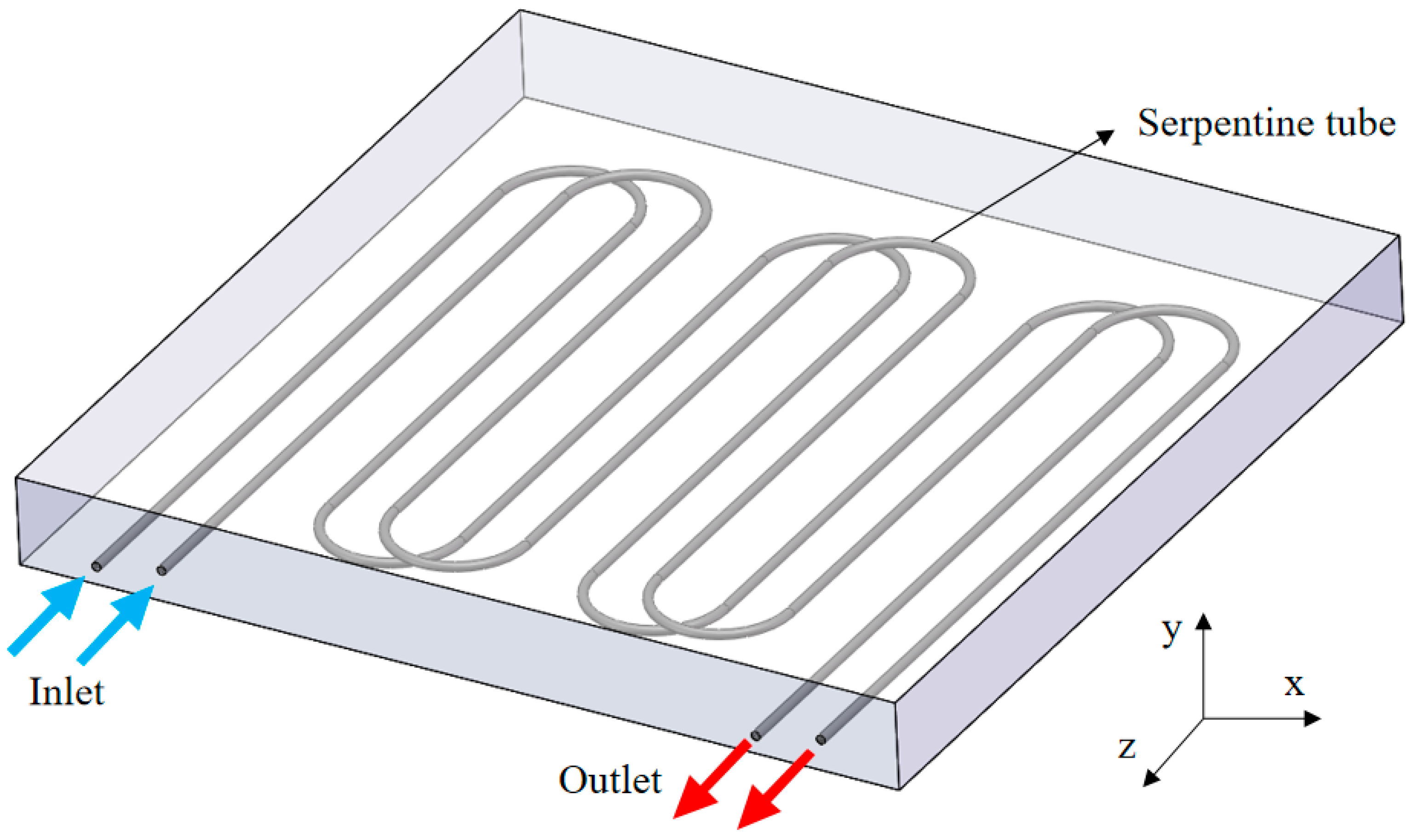
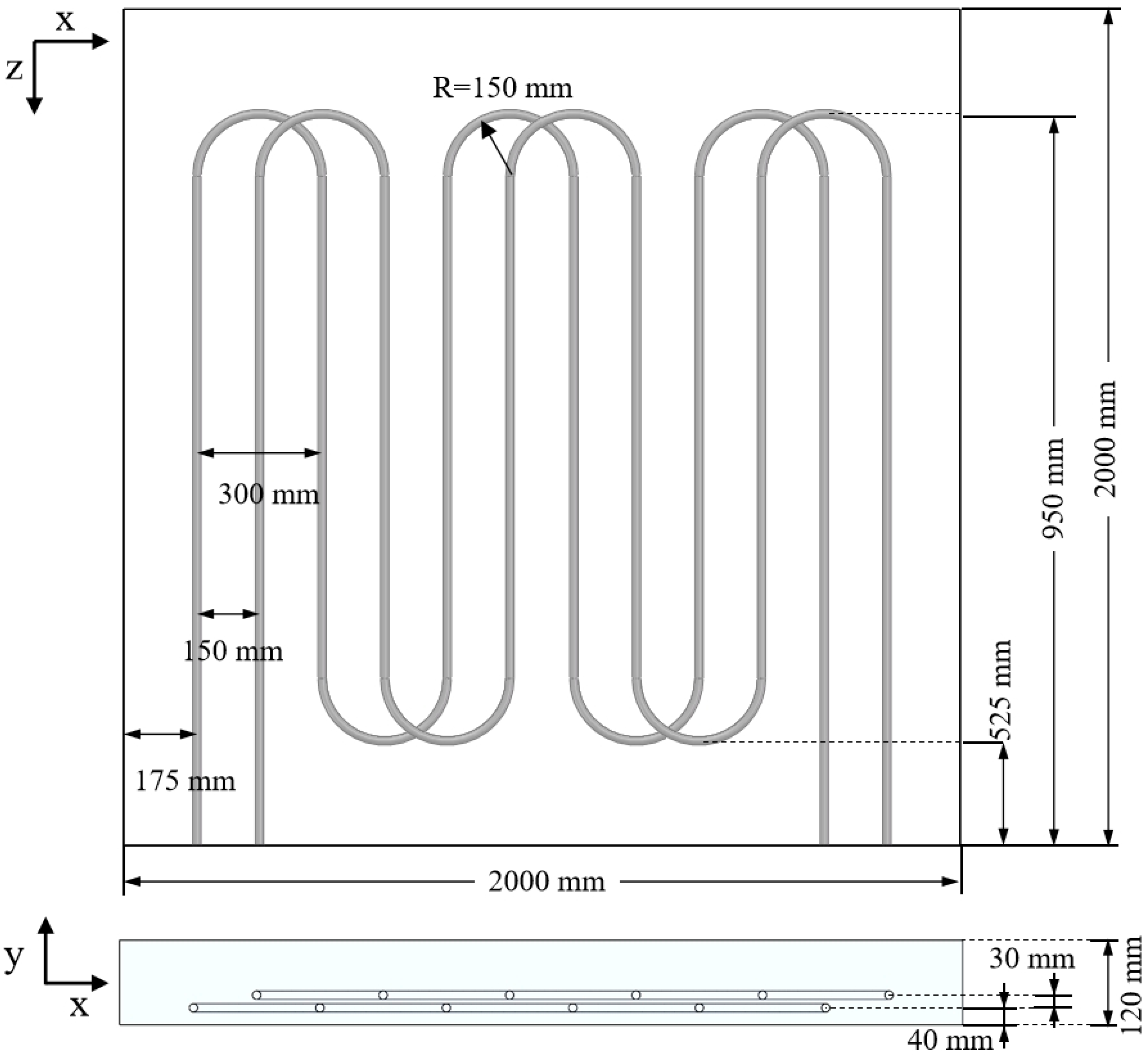
2.1. Physical Model
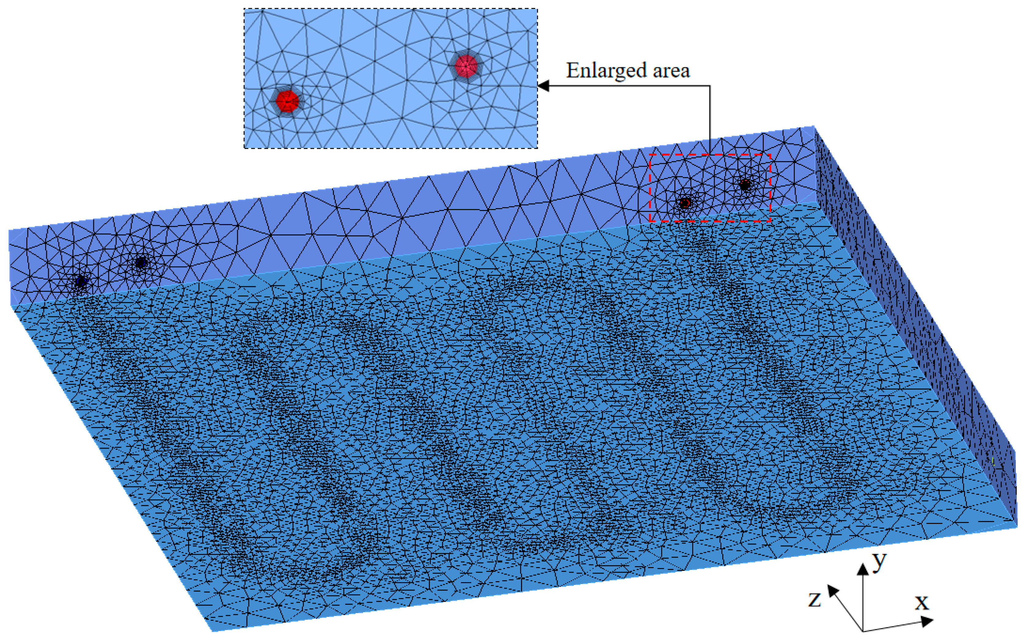
2.2. Meshing
2.3. Mathematical Model
2.4. Material Parameters
2.5. Boundary Conditions
2.6. Solving Method
3. Numerical Verification
4. Results and Discussions
4.1. Heat Transfer Performance of the Concrete Radiant Roof
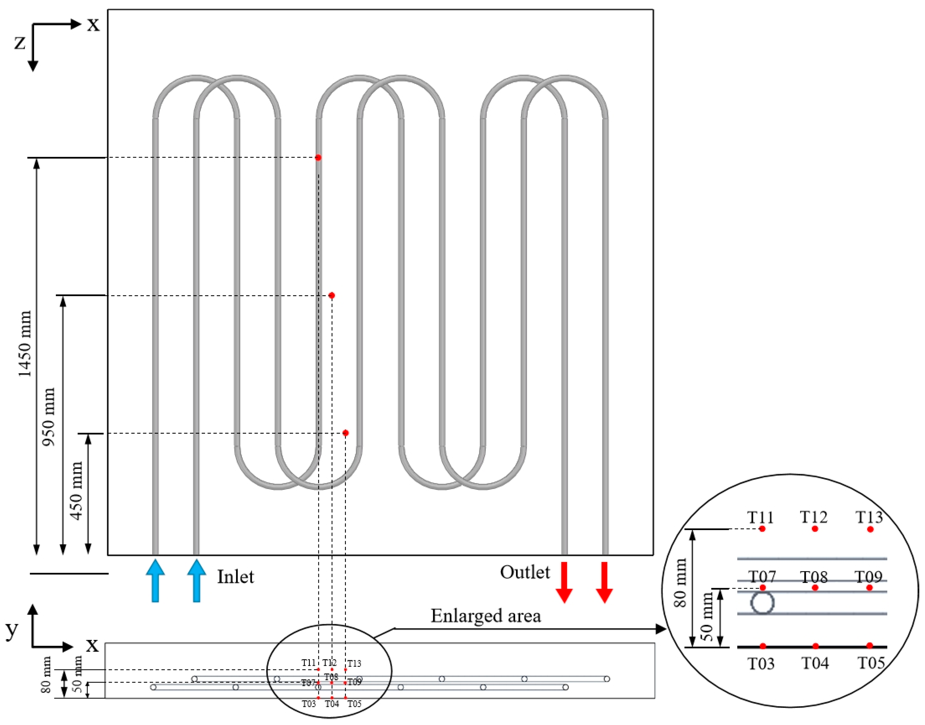
4.2. Temperature Uniformity Analysis
4.3. Anti-Condensation Temperature Control Strategy
5. Conclusions
- In terms of the accuracy of the research, the simulation error was less than 5% compared with the experimental results of Su et al. [23];
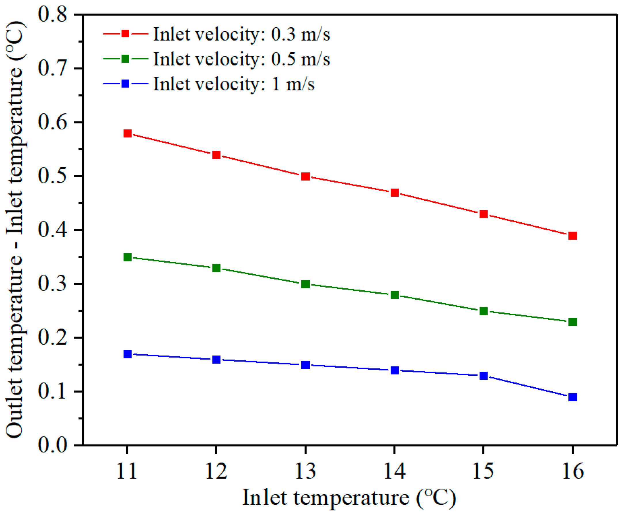
- In thermal performance research, the cooling capacity increased with the increase in inlet flow rate and the decrease in temperature. Compared with the inlet flow rate, the inlet temperature significantly impacted the cooling capacity and radiant surface temperature, which could be used as the primary adjustment parameter of the subsequent anti-condensation temperature control strategy;
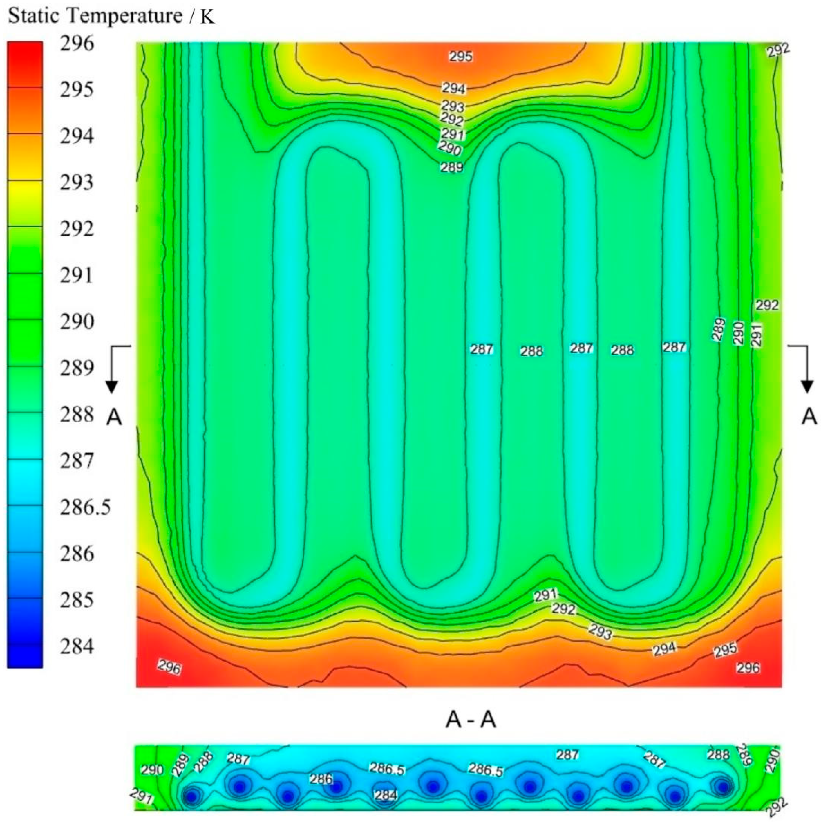
- In the uniformity study, the temperature uniformity of the concrete radiant roof was not ideal, and the difference between the maximum and minimum temperatures was as high as 9.06 °C. The distance between the serpentine pipes area and the concrete edge became the fundamental reason that affected the temperature uniformity. The distance between the serpentine pipes and the radiant surface’s outer edge of less than 200 mm was more conducive to maintaining the temperature uniformity of the radiant surface;
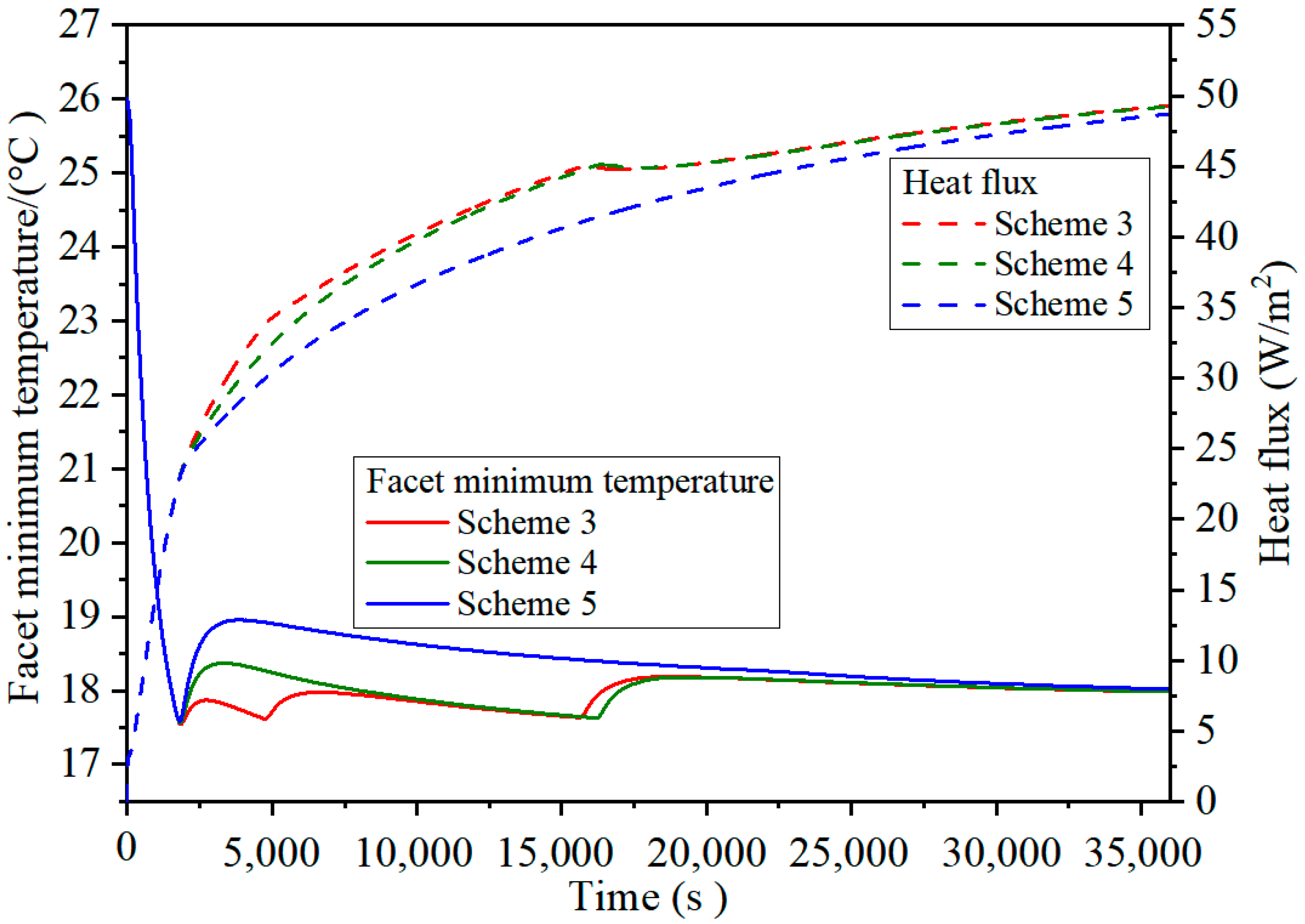
- Regarding anti-condensation and performance improvement research, first supplying water at low temperatures and then dynamically adjusting high-temperature water could effectively avoid condensation and improve the radiant roof’s heat transfer performance. Nevertheless, the performance improvement was limited to the cooling process. For the long-term stable operation of the radiation roof, the inlet temperature was usually stable and unchanged, maintained at a high value. The water supply temperature, when the radiant roof was finally stabilized, was still limited by the dew point temperature.
Author Contributions
Funding
Conflicts of Interest
References
- Rhee, K.N.; Kim, K.W. A 50 year review of basic and applied research in radiant heating and cooling systems for the built environment. Build. Environ. 2015, 91, 166–190. [Google Scholar] [CrossRef]
- Tian, Z.; Love, J.A. A field study of occupant thermal comfort and thermal environments with radiant slab cooling. Build. Environ. 2008, 43, 1658–1670. [Google Scholar] [CrossRef]
- Rhee, K.N.; Olesen, B.W.; Kim, K.W. Ten questions about radiant heating and cooling systems. Build. Environ. 2017, 112, 367–381. [Google Scholar] [CrossRef] [Green Version]
- Karmann, C.; Schiavon, S.; Bauman, F. Thermal comfort in buildings using radiant vs. all-air systems: A critical literature review. Build. Environ. 2016, 111, 123–131. [Google Scholar] [CrossRef] [Green Version]
- Olesen, B.W.; De Carli, M.; Scarpa, M.; Koschenz, M. Dynamic evaluation of the cooling capacity of thermal active building systems. ASHRAE Trans. 2006, 112, 350–357. [Google Scholar]
- Hu, R.; Niu, J. A review of the application of radiant cooling and heating systems in Mainland China. Energy Build. 2012, 52, 11–19. [Google Scholar] [CrossRef]
- Psomas, T.; Teli, D.; Langer, S.; Wahlgren, P.; Wargocki, P. Indoor humidity of dwellings and association with building characteristics, behaviors and health in a northern climate. Build. Environ. 2021, 1, 107885. [Google Scholar] [CrossRef]
- Memon, R.A.; Chirarattananon, S.; Vangtook, P. Thermal comfort assessment and application of radiant cooling. Build. Environ. 2008, 43, 1185–1196. [Google Scholar] [CrossRef]
- Zhang, L.Z. Energy performance of independent air dehumidification systems with energy recovery measures. Energy 2006, 31, 1228–1242. [Google Scholar] [CrossRef]
- Ziarani, N.N.; Haghighi, A.P. Anticipating an efficient relative humidity in a room under direct solar radiation and equipped by radiant cooling panel system. Int. J. Refrig. 2019, 98, 98–108. [Google Scholar] [CrossRef]
- Jin, W.; Jiang, J.; Jia, L.; Wang, Z. The dynamic effect of supply water flow regulation on surface temperature changes of radiant ceiling panel for cooling operation. Sustain. Cities Soc. 2019, 52, 101765. [Google Scholar] [CrossRef]
- Jin, W.; Ma, J.; Jia, L.; Wang, Z. Dynamic Variation of Surface Temperatures on the Radiant Ceiling Cooling Panel based on the Different Supply Water Temperature Adjustments. Sustain. Cities Soc. 2019, 52, 101805. [Google Scholar] [CrossRef]
- Wongkee, S.; Chirarattananon, S.; Chaiwiwatworakul, P. A field study of experimental of radiant cooling for residential building in a tropical climate. J. Autom. Control. Eng. 2014, 2, 67–70. [Google Scholar] [CrossRef] [Green Version]
- Conroy, C.L.; Mumma, S.A. Ceiling radiant cooling panels as a viable distributed parallel sensible cooling technology integrated with DOAS. ASHRAE Trans. 2001, 107, 578–588. [Google Scholar]
- Kang, Z.; Peng, X.; Cheng, X.; Feng, G. Analysis of condensation and thermal comfort of two kinds of compound radiant cooling air conditioning systems based on displacement ventilation. Procedia Eng. 2017, 205, 1529–1534. [Google Scholar] [CrossRef]
- Hout, M.; Ghaddar, N.; Ghali, K.; Ismail, N.; Simonetti, M.; Fracastoro, G.V.; Virgone, J.; Zoughaib, A. Displacement ventilation with cooled liquid desiccant dehumidification membrane at ceiling; modeling and design charts. Energy 2017, 139, 1003–1015. [Google Scholar] [CrossRef]
- Chun, L.; Gong, G.; Fang, X.; Peng, P. Thermodynamic performance assessment of vacuum membrane-based dehumidification and air carrying energy radiant airconditioning system (vmd-acers). Chin. J. Chem. Eng. 2021, 34, 217–227. [Google Scholar] [CrossRef]
- Tang, H.; Liu, X.H.; Li, H.; Zhou, Y.; Jiang, Y. Study on the reduction of condensation risks on the radiant cooling ceiling with superhydrophobic treatment. Build. Environ. 2016, 100, 135–144. [Google Scholar] [CrossRef]
- Ning, B.; Chen, Y.; Liu, H.; Zhang, S. Cooling capacity improvement for a radiant ceiling panel with uniform surface temperature distribution. Build. Environ. 2016, 102, 64–72. [Google Scholar] [CrossRef]
- Kong, X.; Zhang, D.; Zhang, X. Design and analysis of “leading condensation” radiant panel. J. Jiangsu Univ. Sci. Technol. Nat. Sci. Ed. 2011, 25, 440–442. [Google Scholar]
- Gao, J.; Zhang, D.; Yang, M. The influence of mesh generation on the results of flow solving in working face and gob. Procedia Eng. 2013, 37, 125–131. [Google Scholar] [CrossRef] [Green Version]
- Lu, Y. Heating and Ventilation Design Manual, 1st ed.; China Building Industry Press: Beijing, China, 1987; pp. 96–120. [Google Scholar]
- Su, L.; Li, N.; Zhang, X. Experimental Study on Cooling Characteristics of Concrete Ceiling Radiant Cooling Panel. Procedia Eng. 2015, 121, 2168–2175. [Google Scholar] [CrossRef] [Green Version]


| Materials | Density kg/m3 | Thermal Conductivity W/(m2·K) | Specific Heat J/(kg·K) |
|---|---|---|---|
| Concrete | 2500 | 1.74 | 920 |
| Water | 998.2 | 0.6 | 4182 |
| Zone | Type | Name | Boundary Conditions |
|---|---|---|---|
| Water | Velocity-inlet | Inlet | Velocity Specification Method: Magnitude, Normal to Boundary |
| Reference Frame: Absolute | |||
| Velocity Magnitude: 0.3–1 m/s | |||
| Temperature: 284–289 K | |||
| Supersonic Gauge Pressure: 0 Pa | |||
| Pressure-outlet | Outlet | Backflow Reference Frame: Absolute | |
| Gauge Pressure: 0 Pa | |||
| Pressure Profile Multiplier: 1 | |||
| Back Direction Specification Method: Normal to Boundary | |||
| Backflow Pressure Specification: Total Pressure | |||
| Wall | Wall of serpentine pipes | Thermal conditions: coupled | |
| Concrete | Wall | Model top | Thermal conditions: Heat Flux = 0 W/m3 |
| Wall | Model surrounding surface | Thermal conditions: Heat Flux = 0 W/m3 | |
| Wall | Model underside | Thermal conditions: Mixed | |
| Heat Transfer Coefficient: 1.85 W/(m2·K) | |||
| Free Stream Temperature: 299 K | |||
| External Emissivity: 0.95 | |||
| External Radiation Temperature: 299 K |
| Experimental Condition | Inlet Temperatures (°C) | Inlet Flow (m3/h) | Ambient Temperature (°C) |
|---|---|---|---|
| Case 1 | 12 | 0.3266 | 26.4 |
| Case 1 | 13.3 | 0.3349 | 26.4 |
| Time | Inlet Temperature | |||||
|---|---|---|---|---|---|---|
| 11 °C | 12 °C | 13 °C | 14 °C | 15 °C | 16 °C | |
| Scheme 1 | 1705 s | 1000 s | / | / | / | / |
| Scheme 2 | 1705 s | / | 1000 s | / | / | / |
| Scheme 3 | 1705 s | / | / | 2895 s | 9330 s | 22,070 s |
| Scheme 4 | 1705 s | / | / | / | 14,300 s | 19,995 s |
| Scheme 5 | 1705 s | / | / | / | / | 34,295 s |
Disclaimer/Publisher’s Note: The statements, opinions and data contained in all publications are solely those of the individual author(s) and contributor(s) and not of MDPI and/or the editor(s). MDPI and/or the editor(s) disclaim responsibility for any injury to people or property resulting from any ideas, methods, instructions or products referred to in the content. |
© 2023 by the authors. Licensee MDPI, Basel, Switzerland. This article is an open access article distributed under the terms and conditions of the Creative Commons Attribution (CC BY) license (https://creativecommons.org/licenses/by/4.0/).
Share and Cite
Zhang, B.; Sun, Q.; Su, L.; Dong, K.; Luo, W.; Guan, H.; Shao, Z.; Wu, W. Anti-Condensation Temperature Control Strategy of the Concrete Radiant Roof. Energies 2023, 16, 4826. https://doi.org/10.3390/en16124826
Zhang B, Sun Q, Su L, Dong K, Luo W, Guan H, Shao Z, Wu W. Anti-Condensation Temperature Control Strategy of the Concrete Radiant Roof. Energies. 2023; 16(12):4826. https://doi.org/10.3390/en16124826
Chicago/Turabian StyleZhang, Bobo, Qin Sun, Lin Su, Kaijun Dong, Weimin Luo, Haifeng Guan, Zhenhua Shao, and Wei Wu. 2023. "Anti-Condensation Temperature Control Strategy of the Concrete Radiant Roof" Energies 16, no. 12: 4826. https://doi.org/10.3390/en16124826