Article

Simulation Research on the Optimization of Domestic Heat Pump Water Heater Condensers

School of Mechanical Engineering, Shaanxi University of Technology, Hanzhong 723001, China
*
Author to whom correspondence should be addressed.
Energies 2023, 16(21), 7441; https://doi.org/10.3390/en16217441
Submission received: 10 August 2023 / Revised: 4 September 2023 / Accepted: 12 September 2023 / Published: 4 November 2023

Abstract

:
To improve the heat transfer coefficient of a condenser, this paper proposes using a fin-tube condenser to replace a smooth-tube condenser in a domestic heat pump water heater. The finite element method is used to analyze the heat transfer coefficient of fin-tube condensers with different design parameters. By comparing the results of experiments with those obtained using CFD methods, it has been determined that the CFD method used in this study is feasible. Simulation results showed that the heat transfer coefficient enhanced clearly. The total thermal resistance of the fin-tube condenser decreased by 7% through increasing fin thickness. The total thermal resistance of the fin-tube condenser increased by 1–1.3% when fin spacing was increased. The heat transfer coefficient decreased severely and the maximum total thermal resistance of the fin-tube condenser increased by 8.7% with increasing fin height. In 600 s, when the fin spacing, fin height, fin thickness and inner diameter were 14 mm, 12.5 mm, 1.2 mm and 22.5 mm, respectively, compared to the smooth-tube condenser, the fin-tube condenser could increase the final water temperature by 18.37%, and the heat transfer coefficient would increase by about 95%. This research could provide a low-cost way to improve the heat transfer coefficient of condensers in domestic heat pump water heaters.

1. Introduction

Heat pump water heaters have become an indispensable part of daily life, for example, in domestic water supply. However, most heat pump water heaters still have a large capacity to improve their heat transfer efficiency, which have become a focus issue. For domestic heat pump water heater storage tanks, the link between the internal heat exchanger and the heat capacity of the tank is inseparable. In practice, due to its simple heat transfer mechanism, low cost, easy maintenance and other advantages, smooth-tube heat exchangers and fin-tube heat exchangers are applied widely. However, as the heat transfer coefficient of smooth-tube heat exchangers is lower than that of fin-tube heat exchangers, it has become one of key factors that restrict the heat transfer coefficient of condensers. From a structural point of view, the heat transfer area becomes larger because of the fins of fin-tube heat exchangers. Considering the external conditions, when the external disturbance increased, i.e., the external convective heat transfer coefficient increased, fins on the fin-tube could intensify the level of disturbance to increase the convective heat transfer coefficient to increase the heating efficiency.
Numerous published papers focused on the heat capacity efficiency of different types of heat exchangers. Dizaji et al. [1] studied the heat transfer and pressure drop characteristics of bellows heat exchangers. Zachár et al. [2] studied the heat production capacity of a tank with a coil heat exchanger in terms of temperature stratification. A numerical analysis of heat transfer between a U-shaped fin-tube and a smooth-tube was carried out by Beemaraj et al. [3] via CFD methods. Yu et al. [4] conducted an analytical solution research for the velocity and temperature distribution of a low-Reynolds-number flowing fluid in a spiral tube. Pai et al. [5] studied the heat transfer characteristics of a fin-tube by adding fins into the tube. Nuntaphan et al. [6] investigated the heating effect and pressure-drop characteristics of spiral fins. FaJiang et al. [7] investigated the heat transfer effect of 13 different tube diameters with spiral fins in more detail. Aside from fin-tubes, there were also numerous research studies that adapted coil and smooth-tube into their experiments, such as [8,9,10]. It could be seen that although the heat transfer efficiency could be enhanced by adding fins, there were differences in the heat transfer performance of fin-tubes that possessed different fin spacing, fin thickness, fin height and other design parameters.
The above research works demonstrated that an enhanced heat transfer efficiency could be achieved by increasing the heat transfer area. Moreover, the heat production capacity could also be enhanced by means of an appropriate increase in external disturbance. S Pethkool et al. [11] investigated the enhancement of turbulent heat transfer in threaded bellows. Cafiero et al. [12] proposed an approach to enhance heat transfer efficiency by applying an impinging jet. Abraham et al. [13] conducted a study on the heat capacity performance of heat exchangers with multiple rows of spiral fin-tubes and found that the heat transfer coefficients were almost constant for four and five rows of heat exchangers within a set Reynolds number range. Liu et al. [14] designed a wavy fin and used it to increase the heat transfer coefficient in the external work fluid. Tang et al. [15] designed a new fin-tube heat exchanger from the fin perspective and obtained the variation of the Euler and Nussle numbers in this heat exchanger. Kiatpachai et al. [16] compared the differences between fin-tubes made up of embedded fins and welded fins in terms of the Colburn factor, etc. For the simulation of fin-tube heat exchangers, many different studies have been carried out so far. Singh V. et al. [17] conducted CFD simulations of a fin-tube heat exchanger on the air-refrigerant side and the error between the 2D and 3D simulations did not exceed 4%. There have also been many simulations of fin-tube structures, such as that by Taler et al. [18], wherein the authors replaced the round tube in a conventional fin-tube with an elliptical tube and performed CFD simulations. Chen et al. [19] designed an annular elliptical fin and determined the optimum fin spacing of 18 mm by means of simulation experiments. Batista presented the conclusion that when evaluating the air-side and overall heat transfer, the water-side thermal resistance could not be neglected [20].
For reducing residential energy consumption, such as that from a domestic heat pump water heater, many scholars have also researched and explored this area. Guo et al. [21] proposed a domestic heat pump water heater system using the latent heat of frost for domestic wastewater, which uses wastewater as a heat source, and experimental data were obtained under different working conditions; the system proved to be able to save 60% of energy consumption compared with the traditional electric water heater. Al-Joboory [22] conducted a study on heat pipe solar water heater. The corresponding effect of the water heater on the load was studied under different load conditions and compared with the temperature control system, and it was found that the system was better than the reference system under different load conditions and optimal under intermittent load conditions. Zukowski [23], in order to solve the effect of evaporation temperature and condensation temperature on the energy efficiency of heat pumps, proposed to use the solar air heater as a preheating device to preheat air-source heat pumps to improve heat pump performance. The results showed that this device can reduce the maximum annual power consumption by about 16%. Engel et al. [24] studied the heat pump water heaters using reciprocating compressors and rolling piston compressors and tested their operational performance under different operating conditions. The results showed that the COP of the heat pump system with a rolling piston compressor was better than that of the system with a reciprocating compressor under different operating conditions, and the highest COP improvement of 12.6% was achieved in summer operating conditions. In addition, there are also many scholars studying the control strategy of the system, such as Ma et al. [25], on the housing energy consumption prediction, proposing a more effective PS-LSTM prediction method.
There have been a lot of research about different types of condensers, but the ways in which to improve performance at lower costs are lacking. One example is the fin-tube condenser, which, due to its simple structure, high heat transfer coefficient and low cost is a suitable replacement for the smooth-tube condenser in conventional water tanks to improve heat capacity. However, the approaches of fin-tube condensers as replacements for smooth-tube condensers in conventional storage tanks have not been deeply investigated in the published literature. Therefore, this research compares the efficiency of fin-tube condensers and smooth-tube condensers with experimental and simulation approaches to investigate the feasibility of applying fin-tube condensers as heat exchangers in domestic heat pump water heaters. The novelty of this study is focused on small-capacity domestic heat pump water heater components and therefore can be used to optimize existing products.

2. Method

2.1. Simulation Setup

This study used COMSOL to solve a heat transfer flow model based on the fin-tube parameters derived from an iterative program. By comparing the temperature variation between the same mass of water heated by fin-tubes and that by smooth-tubes of the same length, the superiority of fin-tubes over smooth-tubes in terms of heat transfer coefficient was demonstrated.
With regard to the fin-tube condenser under study, Figure 1 provides a detailed description of structural parameters of the prototype, where f t (mm) is the fin thickness, f s (mm) is the fin spacing, f h (mm) is the fin height, d (mm) is the inner tube diameter and D (mm) is the outer tube diameter. Due to the thermal convection effect, the condenser was set at the bottom of the tank, as shown in Figure 2, where the fin-tube was surrounded by the water to be heated, and was designed to be compact in order to enhance the heat transfer coefficient of Tian [26]. The aim of this study was to investigate the enhanced heat transfer coefficient of a domestic heat pump water heater tank which used a fin-tube condenser to replace the former smooth-tube condenser. The length of smooth-tube was calculated with the condition in which 40 L water was heated from 15 °C to 45 °C in 600 s. The changes of water temperature were compared to study the performance of condensers with different design parameters. Since most of the refrigerant underwent a phase change of exothermic heat in the condenser, the inner wall temperature was determined as the internal heat source. The mesh used for the model is shown in Figure 3
Overall study calculations were based on the following assumptions:
  • Liquid encapsulating heat exchangers were treated as continuous laminar flow.
  • Fluid was incompressible.
  • Solution domain mass was conserved.
  • The inner wall temperature was a fixed value.
The mathematical expression was:
u t + u u x + v u y = 1 p p x + v 2 u y 2 u x + u y = 0 D ρ D t = 0

2.2. CFD Simulation

The experiment was divided into the following parts: the inner walls of the smooth-tube and fin-tube with constant temperature; fin-tubes with different design parameters. In order to compare the heat transfer coefficient of the smooth-tube and the fin-tube, a section of the smooth-tube and the fin-tube were taken and the control equations were elaborated from solid and fluid heat transfer and fluid flow, respectively.

Heat Transfer between Solid and Fluid

The general equation in terms of heat transfer is
ρ C p T t + ρ C p u T + q = Q q = k T
where u (m/s) is the velocity field of the fluid and Q (W) is the total heat gain.
The equation for the solid domain is
ρ C p T t + ρ C p u T + q = Q i n + Q n e t q = k T
where Q i n (W) is the heat generated by the internal heat source and Q n e t (W) is the net heat flow into the system.
The governing equation for the fluid domain is
ρ C p T t + ρ C p u T + q = Q + Q s + Q v d q = k T
where Q s (W) is the surface force power, which includes viscous dissipation as the fluid was set to be viscous Q v d (W) and could be obtained by
Q v d = τ : n
To facilitate the study, the model was set up as adiabatic on the outside, with the equation:
n q = 0
In this study, the fluid outside the smooth-tube was set as a laminar flow, corresponding to the N–S equation and the continuity equation as:
ρ u t + ρ u u = p E + K + F + ρ g ρ t + ρ u = 0
In the above equation, where E is the unit tensor, K is the viscous term and the gravity term g is added because of the need for overall thermal convection phenomena.

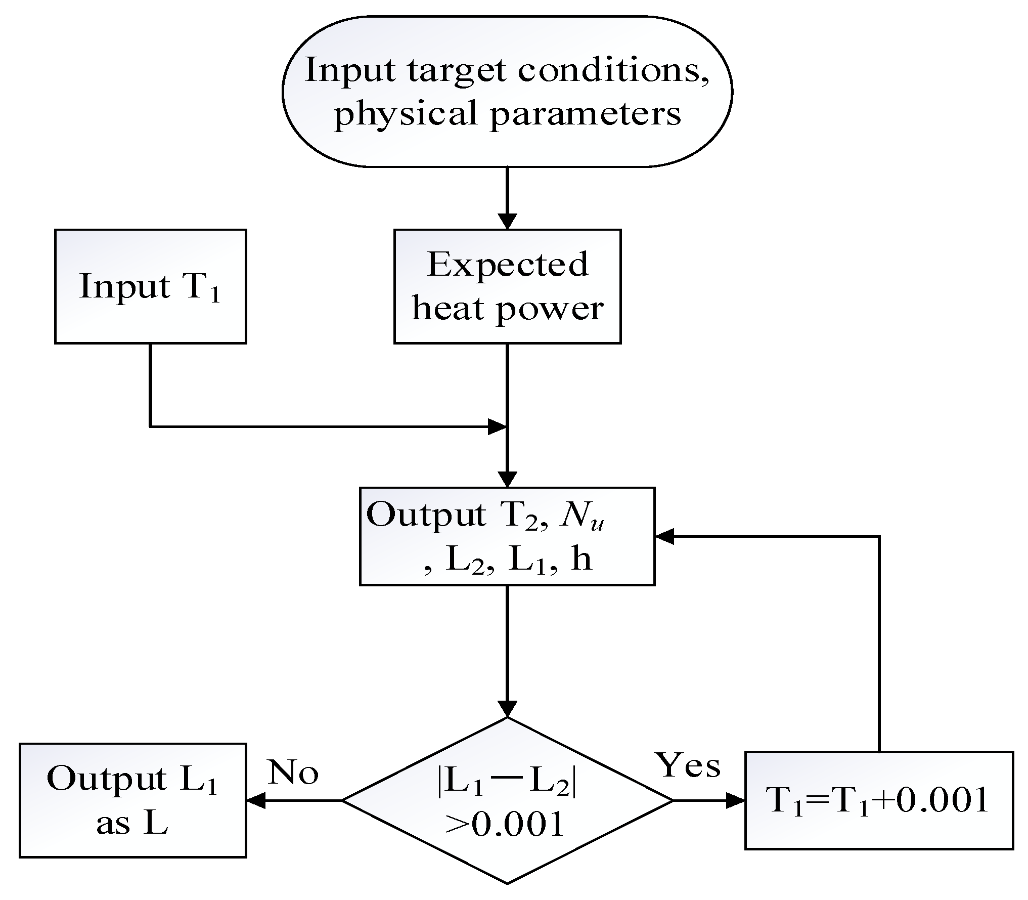
2.3. Post-Process Data Analysis

Firstly, the temperature and heating time of the water should be determined in order to calculate the required power. The arithmetic mean of initial and final temperatures was taken as the mean temperature outside the tube:
Q = q t = c m Δ T t
The temperature of tube inner wall was set as T1 = 85 °C.
When the heat transfer of system as steady state, i.e., when the temperature of the tube body was stabilized, the total heat outflow from tube Q and the total heat inflow outside tube Q1 were equal. Two equations were developed for the overall heat transfer in the two stages of conduction/convection:
T 1 T 2 = Q ln D d 2 π k c o p p e r L Q 1 = h D L 2 π D T 2 T m 2
In the formula, Q and Q1 are the proposed power; L (mm) is the tube length; d (mm) and D (mm) are the inner and outer diameters of the tube, respectively; Tm2 is the average temperature of water outside the pipe; T1 and T2 are the internal and external temperatures of the tube wall, respectively. T1, T2 and L were solved using an iterative program (Figure 4), which was verified in several simulations to provide more accurate design parameters for the required tube length L; below is the corresponding flow chart.

2.4. Model Verification

In order to verify the feasibility of the CFD method used in this study, experiments and CFD simulations were performed on fin-tube and smooth-tube heaters under constant heat flux conditions. The final water temperature difference was compared to validate the feasibility of the CFD method.
Figure 5 shows a schematic diagram of the experimental setup, where heat loss is minimized by wrapping the tank with an insulation material. A thermometer of an electric heater with a small water circulation pump is placed inside the tank. All were powered by 220 V, while the thermometer was connected to data collection to collect temperature data.
The experiment used a 30 L insulated water tank with a fin-tube electric heater and a smooth-tube electric heater whose parameters, except for the fin parameters, were the same. In consideration of the convective heat transfer effect, the electric heater was placed in the lower part of the water tank, and a small circulating water pump was used to avoid temperature stratification in the water tank. The temperature change detected by the temperature sensor within the water tank for 1800 s was used as a reference for comparison with the temperature change obtained using the CFD method. The error between the two was compared to ensure the feasibility of the CFD method. Figure 6 shows the trend of temperature change inside the water tank obtained through experiments and CFD methods. The results in Figure 6 show that the error between experimental data and CFD data is less than 10%, indicating that the CFD method used in this study is indeed feasible. The y-axis in Figure 6 is the temperature of the water around the heat exchanger.

3. Results and Discussion

In order to simulate the heat production process of a fin-tube condenser in a heat pump water heater tank, a finite element model was established in COMSOL; the flow and heat transfer control equations were solved with finite element, which used tetrahedral meshes, and the relative tolerance of that model was set as 10−4. The fin-tubes were oriented perpendicularly to gravity to maximize the thermal convection effect. Table 1 shows the characteristics of the used computer.

3.1. Description of the Simulation Test

In response to the low heat transfer coefficient in the heat pump water heater tank, we propose to replace the existing smooth-tube condenser with a fin-tube condenser. Firstly, mesh-independence verification was carried out to ensure that the developed finite element model was insensitive to the number of meshes. The internal wall temperature, target heating temperature and target time were used to calculate the tube flow rate and heat transfer coefficient, and the tube length was calculated with an iterative program. For the first test, a comparison was made between the temperature changes of water heated by a smooth-tube condenser and a fin-tube condenser during the target time, respectively. For the second test, the design parameters of the prototype were modified to investigate the effect of each parameter change on the heat transfer coefficient. The total thermal resistance and water temperature of different fin-tube condensers were calculated for comparison to demonstrate the effect of different parameters on the heat transfer coefficient. The time step for all calculations was 1 s.

3.2. Grid-Independent Verification

For the proposed model, it can be seen from Figure 7 that when the number of grids was 4 million and more, the final temperature of the model fluctuates around 31 °C and the error does not exceed 5%, so it can be considered that the temperature of this model was independent with the number of grids.

3.3. Presentation of Results

After results were obtained using the program written in Python3.7, the main comparison was made among the temperature variations of the external waters in order to investigate the advantages and disadvantages of the different fin-tubes. The above temperatures were taken as volume averages and surface area averages.
In order to improve the performance of the fin-tube, the following specifications shown in Table 2 were proposed to be used with the smooth-tube.

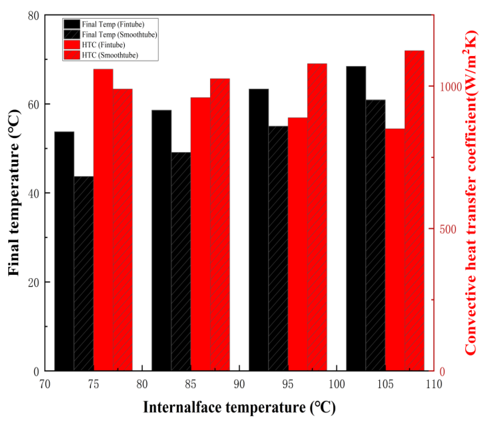
3.3.1. Performance Differences among Fin-Tubes and Smooth-Tubes at Different Constant Internal Wall Temperatures

The first test was set to investigate the difference in heat capacity performance among the prototype fin-tube and the smooth-tube, which had different inner wall temperatures within 600 s. The difference was quantified and compared by the convective heat transfer coefficient and total thermal resistance.
As shown in Figure 8, the heat capacity performance of the fin-tube condenser was better than that of the smooth-tube condenser at different constant wall temperatures. At constant internal wall temperatures of 75, 85, 95 and 105 °C, the heat transfer coefficients of the fin-tube were 1059.55, 959.95, 889.12 and 850.4 W/m2K, respectively, while the heat transfer coefficients of the smooth-tube were 989.92, 1026.15, 1078.7 and 1124.42 W/m2K, respectively. The convective heat transfer coefficients improved by 7.03%, −6.45%, −17.57% and −24.37%. However, overall, the heat transfer coefficients of fin-tubes were 30,400 W/K, 27,785, 26,013 and 24,733 W/K, whereas the heat transfer coefficient of smooth-tubes were 15,174, 16,320, 17,231 and 17,972 W/K. Although the overall heat transfer coefficient of fin-tubes was higher than that of smooth-tubes, the coefficients per unit area were not all higher than that of smooth-tubes, because fin-tubes increased the heat transfer coefficients by increasing external area.

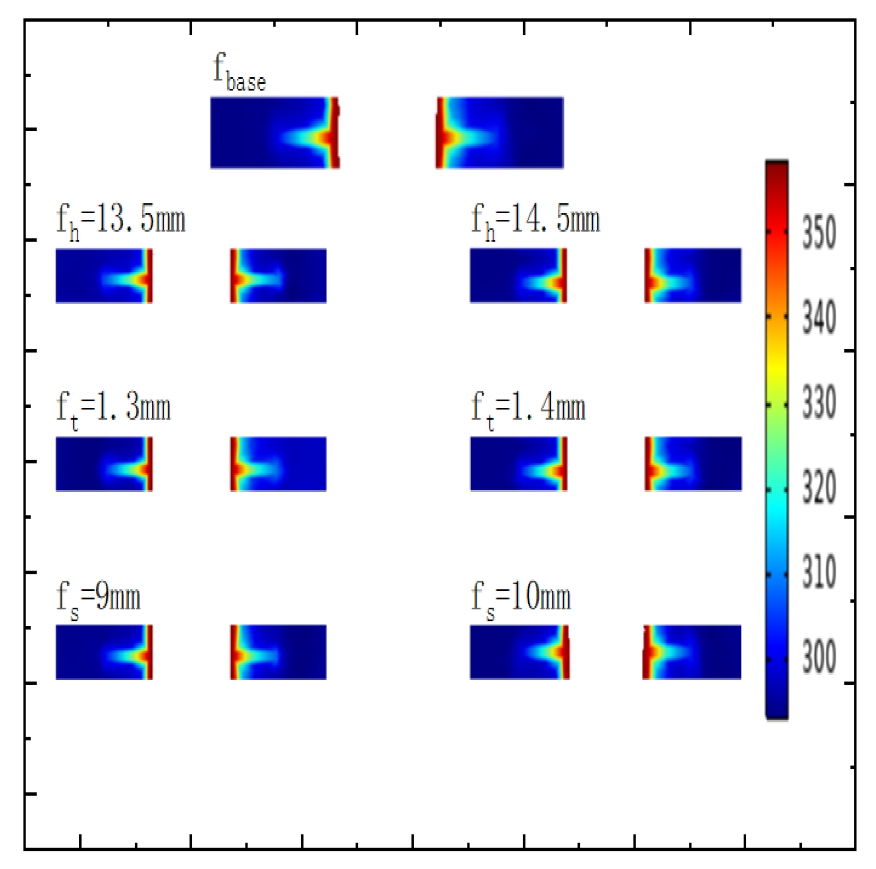
3.3.2. Changes of Fin-Tube Performance with Various Parameters

Second simulation experiments were carried out by varying the design parameters of the prototype fin-tube at a constant internal wall temperature. As shown in Figure 9, the final temperature changed with each case after changing each parameter. It was found that when the fin height increased, the final temperature would first drop to 40 °C, and then gradually stabilize at around 58 °C; when increasing the fin thickness, the final temperature was the highest when the fin thickness was 1.3 mm and then decreased and maintained at around 54 °C. The final temperature did not change significantly when the fin pitch was increased from 8 mm to 13 mm, but rose to 58 °C when it increased to 14 mm. The final temperature rose with the inner diameter of the tube until 25.5 mm and was lower than 58 °C from 25.5 mm to 28.5 mm.
It was noted that, although a slight change in the inner diameter of the tube can enhance the heat transfer efficiency, the same water temperature could be achieved when the fin height reached 15.5 mm and above, while the heat transfer efficiency decreased when the inner diameter of the tube was higher than 25.5 mm. Therefore, from the manufacturing aspect, it was easier to obtain a higher heat transfer efficiency by increasing the fin height.
Figure 10 shows the final temperature variation of water heated by different fin-tubes with different inner diameters. From the former results, as the optimum fin thickness was 1.3 mm, the inner diameter of the fin-tube was changed to investigate the effect of different inner diameters on heat transfer efficiency. When the inner diameter of the fin-tube was increased from 22.5 mm to 25.5 mm, the heat transfer coefficients increased by 1.2%, 7.1% and 13.1%, respectively, and then, the heat transfer coefficient declined with the increase in inner diameter. It was found that when the inner diameter of the fin-tube increased, the overall heat transfer coefficient of the fin-tube would first increase and then decrease.
Figure 11 shows the profile temperature distribution of the fin-tubes. From the figure, it can be seen that when the fin height increases, the temperature of the fins decreases, while there is no significant change in the temperature when the fin spacing and thickness increase.
According to the above simulation results, in 600 s, when the fin spacing, fin height, fin thickness and inner diameter were 14 mm, 12.5 mm, 1.2 mm and 22.5 mm, respectively, compared to the smooth-tube heat exchanger, the fin-tube heat exchanger could increase the final water temperature by 18.37%, and the heat transfer efficiency would increase by about 95%.
From the experimental results and simulation results, it can be seen that the fin-tube heat exchanger has a stronger overall heat transfer capacity under the condition of constant internal wall temperature compared with the smooth-tube heat exchanger. When the difference between the internal and external heat transfer coefficients is small, the heat transfer capacity of the smooth-tube heat exchanger and fin-tube heat exchanger is closer; but because the fin-tube heat exchanger increases the heat transfer area, it can thus be applied to more working conditions.

4. Conclusions

(1)
When the constant internal wall temperature were 75 °C, 85 °C, 95 °C and 105 °C, the prototype fin-tube had a heat transfer coefficient improvement of 7.03%, −6.45%, −17.57% and −24.37% over that of smooth-tube, respectively.
(2)
Heat transfer coefficient enhanced clearly, and the total thermal resistance of the fin-tube condenser decreased by 7% upon increasing the fin thickness.
(3)
The total thermal resistance of the fin-tube condenser increased by 1–1.3% when the fin spacing was increased.
(4)
When the temperature of the inner wall of the tube was 85 °C, the maximum temperature of the external waters could reach 56.46 °C. In 600 s, as fin spacing, fin height, fin thickness and inner diameter were 14 mm, 12.5 mm, 1.2 mm and 22.5 mm, respectively, compared to the smooth-tube condenser, the fin-tube condenser could increase the final water temperature by 18.37%, and the heat transfer efficiency would increase by about 95%.
(5)
It was found that as the inner diameter increased from 22.5 mm to 25.5 mm, the heat transfer coefficients of the fin-tube increased by 1.2%, 7.1% and 13.1%, respectively, and then showed a decreasing trend with a further increase in the inner diameter. Therefore, from a manufacturing point of view, it was easier to obtain a higher heat transfer efficiency by increasing the fin height.
This research confirms the feasibility of replacing a traditional smooth-tube condenser with a fin-tube condenser, provides an improvement in efficiency and optimizes the design parameters of fin-tubes. However, this study has not investigated the detailed reasons for the influence of fin parameters on heat capacity efficiency, but will improve on the detailed analyses of fin-tube parameters and the heat transfer mechanism in subsequent studies. Also, the effects of scale and coating on the heat transfer of thermal resistance have not been considered. This will be one of the directions for future work.

Author Contributions

Data curation, M.G.; Formal analysis, J.W.; Project administration, R.F. and H.C.; Resources, T.X.; Writing—original draft, Y.H. All authors have read and agreed to the published version of the manuscript.

Funding

The support of the National Natural Science Foundation of China (No. 51706128), Natural Science Basis Research Plan in Shaanxi Province of China (Program No. 2021JM-485), Scientific research plan projects of Shaanxi Education Department (Program No. 21JK0575) are acknowledged.

Data Availability Statement

Data available on request due to restrictions eg privacy or ethical. The data presented in this study are available on request from the corresponding author. The data are not publicly available due to research confidentiality requirements.

Conflicts of Interest

The authors declare that there are no conflict of interest regarding the publication of this article.

Nomenclature

ρ Density (kg/m3)
C p Constant pressure specific heat capacity (J/(kg·°C))
T fTemperature field (°C)
T Temperature (°C)
t Time (s)
u Velocity field (m/s)
q Heat flux (W/m2)
Q Heat (W)
k Thermal conductivity (W/(m·°C))
τ Shear force (N)
E Unit tensor (N)
K Viscous term (Pa·s)
F Body force (N)
g Gravity term (m/s2)
mMass (kg)
h Convective heat transfer coefficient (W/(m2·°C))
c Specific heat capacity (J /(kg·°C))
L Tube length (mm)
Subscript
mMean temperature
dInner diameter
DOuter diameter
fhFin height
fsFin spacing
ftFin thickness

References

  1. Dizaji, H.S.; Pourhedayat, S.; Aldawi, F.; Moria, H.; Anqi, A.E.; Jarad, F. Proposing an innovative and explicit economic criterion for all passive heat transfer enhancement techniques of heat exchangers. Energy 2022, 239, 122271. [Google Scholar] [CrossRef]
  2. Zachár, A. Investigation of a new tube-in-tube helical flow distributor design to improve temperature stratification inside hot water storage tanks operated with coiled-tube heat exchangers. Int. J. Heat Mass Transf. 2013, 63, 150–161. [Google Scholar] [CrossRef]
  3. Ravikumar, M.; Radha Krishnan Beemaraj Arunraja, K.M.; Pandiarajan, P.; Sundaresan, R. Heat transfer analysis in fin and tube exchanger using CFD. Mater. Today Proc. 2022, 52, 1603–1605. [Google Scholar]
  4. Yu, D.; Jeon, W.; Kim, S.J. Analytic study on pressure drop and heat transfer characteristics for low reynolds number flow in spirally finned tubes. Int. J. Heat Mass Transf. 2020, 158, 119849. [Google Scholar] [CrossRef]
  5. Pai, Y.-W.; Yeh, R.-H. Experimental investigation of heat transfer and pressure drop characteristics of internal finned tubes. Int. J. Heat Mass Transf. 2022, 183, 122183. [Google Scholar] [CrossRef]
  6. Nuntaphan, A.; Kiatsiriroat, T.; Wang, C.C. Heat transfer and friction characteristics of crimped spiral finned heat exchangers with dehumidification. Appl. Therm. Eng. 2005, 25, 327–340. [Google Scholar] [CrossRef]
  7. FaJiang, H.; WeiWu, C.; Ping, Y. Experimental Investigation of Heat Transfer and Flowing Resistance for Air Flow Cross over Spiral Finned Tube Heat Exchanger. Energy Procedia 2012, 17, 741–749. [Google Scholar] [CrossRef]
  8. Yulianto, M.; Suzuki, T.; Ge, Z.; Tsuchino, T.; Urakawa, M.; Taira, S.; Miyaoka, Y.; Giannetti, N.; Li, L.; Saito, K. Performance assessment of an R32 commercial heat pump water heater in different climates. Sustain. Energy Technol. Assess. 2022, 49, 101679. [Google Scholar] [CrossRef]
  9. Ye, Q.; Li, S. Investigation on the performance and optimization of heat pump water heater with wrap-around condenser coil. Int. J. Heat Mass Transf. 2019, 143, 118556. [Google Scholar] [CrossRef]
  10. Liu, M.; He, Y.; Zhang, H.; Su, H.; Zhang, Z. The feasibility of solar thermal-air source heat pump water heaters in renewable energy shortage regions. Energy 2020, 197, 117189. [Google Scholar] [CrossRef]
  11. Pethkool, S.; Eiamsa-ard, S.; Kwankaomeng, S.; Promvonge, P. Turbulent heat transfer enhancement in a heat exchanger using helically corrugated tube. Int. Commun. Heat Mass Transf. 2011, 38, 340–347. [Google Scholar] [CrossRef]
  12. Cafiero, G.; Discetti, S.; Astarita, T. Heat transfer enhancement of impinging jets with fractal-generated turbulence. Int. J. Heat Mass Transf. 2014, 75, 173–183. [Google Scholar] [CrossRef]
  13. Abraham, P.; Sharqawy, M.H.; Shawkat, M.E. Thermal and hydraulic characteristics of multiple row spiral finned tube heat exchangers. Int. J. Refrig. 2021, 130, 56–66. [Google Scholar] [CrossRef]
  14. Liu, X.; Wang, M.; Liu, H.; Chen, W.; Qian, S. Numerical analysis on heat transfer enhancement of wavy fin-tube heat exchangers for air-conditioning applications. Appl. Therm. Eng. 2021, 199, 117597. [Google Scholar] [CrossRef]
  15. Tang, S.; Li, H.; Zhou, J.; Li, H.; Zhang, D. Parametric investigation and correlation development for thermal-hydraulic characteristics of honeycomb 4H-type finned tube heat exchangers. Appl. Therm. Eng. 2021, 199, 117542. [Google Scholar] [CrossRef]
  16. Kiatpachai, P.; Kaewkamrop, T.; Mesgarpour, M.; Ahn, H.S.; Dalkılıç, A.S.; Mahian, O.; Wongwises, S. Air-side performance of embedded and welded spiral fin and tube heat exchangers. Case Stud. Therm. Eng. 2022, 30, 101721. [Google Scholar] [CrossRef]
  17. Singh, V.; Abdelaziz, O.; Aute, V.; Radermacher, R. Simulation of air-to-refrigerant fin-and-tube heat exchanger with CFD-based air propagation. Int. J. Refrig. 2011, 34, 1883–1897. [Google Scholar] [CrossRef]
  18. Taler, D.; Ocłoń, P. Determination of heat transfer formulas for gas flow in fin-and-tube heat exchanger with oval tubes using CFD simulations. Chem. Eng. Process. Process Intensif. 2014, 83, 1–11. [Google Scholar] [CrossRef]
  19. Chen, H.-T.; Hsieh, Y.-L.; Chen, P.-C.; Lin, Y.-F.; Liu, K.-C. Numerical simulation of natural convection heat transfer for annular elliptical finned tube heat exchanger with experimental data. Int. J. Heat Mass Transf. 2018, 127, 541–554. [Google Scholar] [CrossRef]
  20. Batista, J.; Trp, A.; Lenic, K. Experimentally validated numerical modeling of heat transfer in crossflow air-to-water fin-and-tube heat exchanger. Appl. Therm. Eng. 2022, 212, 118528. [Google Scholar] [CrossRef]
  21. Guo, J.J.; Wu, J.Y.; Wang, R.Z. A new approach to energy consumption prediction of domestic heat pump water heater based on grey system theory. Energy Build. 2011, 43, 1273–1279. [Google Scholar] [CrossRef]
  22. Al-Joboory, H.N.S. Comparative experimental investigation of two evacuated tube solar water heaters of different configurations for domestic application of Baghdad- Iraq. Energy Build. 2019, 203, 109437. [Google Scholar] [CrossRef]
  23. Zukowski, M.; Woroniak, G. Estimation of energy savings resulting from the cooperation of an air to water heat pump with a solar air heater. Sol. Energy 2023, 250, 182–193. [Google Scholar] [CrossRef]
  24. Engel, R.C.; Deschamps, C.J. Comparative analysis between the performances of reciprocating and rolling piston compressors applied to a domestic heat pump water heater. Int. J. Refrig. 2019, 102, 130–141. [Google Scholar] [CrossRef]
  25. Ma, H.; Xu, L.; Javaheri, Z.; Moghadamnejad, N.; Abedi, M. Reducing the consumption of household systems using hybrid deep learning techniques. Sustain. Comput. Inform. Syst. 2023, 38, 100874. [Google Scholar] [CrossRef]
  26. Tian, L.; He, Y.; Tao, Y.; Tao, W. A comparative study on the air-side performance of wavy fin-and-tube heat exchanger with punched delta winglets in staggered and in-line arrangements. Int. J. Therm. Sci. 2009, 48, 1765–1776. [Google Scholar] [CrossRef]
Figure 1. Prototype fin-tube design parameter (left), partial fin-tube model (right).
Energies 16 07441 g001
Figure 2. Partial prototype fin-tube condenser solution domain.
Energies 16 07441 g002
Figure 3. Solution domain with mash.
Energies 16 07441 g003
Figure 4. Parameter design flow chart.
Energies 16 07441 g004
Figure 5. Schematic diagram of the experimental setup.
Energies 16 07441 g005
Figure 6. Experiment and simulation comparison.
Energies 16 07441 g006
Figure 7. Verification of grid–temperature independence.
Energies 16 07441 g007
Figure 8. Temperature and convective heat transfer coefficient difference between the fin-tube and the smooth-tube at different constant internal wall temperatures.
Energies 16 07441 g008
Figure 9. Final temperature change in surrounding water after changing fin-tube design parameters.
Energies 16 07441 g009
Figure 10. Final temperature variation of water in the different experimental groups.
Energies 16 07441 g010
Figure 11. Profile of temperature distribution of different fin-tubes.
Energies 16 07441 g011
Table 1. Characteristics of the used computer.
ComponentsModel
CPU12th Gen Intel(R) Core(TM) i7-12700KF 3.60 GHz, Intel, Shanghai, China
RAM16.0 GB, Kingston, Shanghai, China
Operating System64-bit
GPUNVIDIA GeForce GTX 1650, GALAX, Qinghai, China
Table 2. Design parameters of the light tube and the prototype fin-tube (mm).
Tube Type/Structure (mm)Inner DiameterOuter DiameterTube LengthFin ThicknessFin HeightFin Spacing
Fin-tube22.5255501.212.55
Smooth-tube22.525550------
Disclaimer/Publisher’s Note: The statements, opinions and data contained in all publications are solely those of the individual author(s) and contributor(s) and not of MDPI and/or the editor(s). MDPI and/or the editor(s) disclaim responsibility for any injury to people or property resulting from any ideas, methods, instructions or products referred to in the content.

