Article

Role of Altitude in Influencing the Spray Combustion Characteristics of a Heavy-Duty Diesel Engine in a Constant Volume Combustion Chamber. Part I: Free Diesel Jet

1
Shenzhen Institutes of Advanced Technology, Chinese Academy of Sciences, Shenzhen 518055, China
2
Institute of Intelligent Manufacturing Technology, Shenzhen Polytechnic, Shenzhen 518055, China
3
School of Automotive Studies, Tongji University, Shanghai 201804, China
4
College of Mechanical Engineering, Guangxi University, Nanning 530004, China
*
Authors to whom correspondence should be addressed.
Energies 2023, 16(12), 4832; https://doi.org/10.3390/en16124832
Submission received: 23 May 2023 / Revised: 14 June 2023 / Accepted: 16 June 2023 / Published: 20 June 2023

Abstract

:
Heavy-duty diesel engines operating in plateau regions experience deteriorated combustion. However, the lack of up-to-date information on the spray-combustion process limits the fundamental understanding of the role of altitude. In this work, the in-cylinder thermodynamic conditions of a real diesel engine operating under different altitudes were reproduced in a constant-volume combustion chamber (CVCC). The liquid spray, ignition, and combustion processes were visualized in detail using different optical diagnostics. Apart from predictable results, some interesting new findings were obtained to improve the understanding of free spray-combustion processes with different altitudes. The spatial distributions of ignition kernels provided direct evidence of higher peak pressure rise rates for high-altitude diesel engines. The percent of stoichiometric air was calculated to confirm that the net effect of altitude was an increase in the amount of air-entrained upstream of the lifted flame; therefore, the soot levels deduced from flame images were inconsistent with those from real engines, revealing that accelerating the soot oxidation process could effectively reduce engine soot emissions in plateau regions. Finally, a novel schematic diagram of the spray flame structure was proposed to phenomenologically describe the role of altitude in influencing the spray-combustion process of a free jet.

1. Introduction

An inescapable fact that the internal combustion engine (ICE) community has needed to take seriously in recent years is that many believe the death of the ICE is desirable and imminent [1]. To this end, many practitioners have provided rational evidence to prove the potential for future progress and the short-term irreplaceability of ICEs [1,2,3]. One application scenario in which ICEs are indispensable is plateau regions. Indeed, there are large populations and industrial operations located in high-altitude regions all over the world. Serrano et al. [4] studied the general topography of Europe and concluded that 19.1% of the European population, that is, almost 100 million people, live in plateau areas with altitudes over 1000 m. Giraldo and Huertas [5] focused on Latin America, where most large cities are located over altitudes of 2000 m, and the traffic densities in these cities are very high. Liu et al. [6] pointed out that nearly 26% of China’s territory is located over 1000 m above sea level, where more than 15 million vehicles are operating. Therefore, it is a global issue to investigate high-altitude engine operation.
Diesel engines provide a primary solution for economic activities and road transportation, especially in plateau regions [7]. The unavoidable reduction in atmospheric pressure with increasing altitude reduces the density of the air inhaled into the cylinder, and thus, when operating in plateau regions, diesel engines suffer from dramatic performance degradation in terms of power, economy, emissions, and durability [8,9,10,11,12,13,14]. In addition, increasingly strict environmental regulations, which include altitude and cold tests, place more stringent requirements on diesel engines operating in high-altitude regions [7]. The aforementioned issues have attracted an unprecedented level of attention from the diesel engine community over the past few decades. As a way to cope with these issues, many researchers have concentrated diverse efforts on understanding the influence of altitude on the spray-combustion process in diesel engines.
Numerous investigations have been performed using dedicated altitude simulation systems, which provide engine intake and exhaust pressure to mimic high-altitude atmospheric conditions. In early research, Shen et al. [15] studied the combustion characteristics of both naturally aspirated and turbocharged diesel engines at three simulated altitudes, and they found that with the increase in the altitude, the ignition delay, the early period rate of the heat release, and the rate of the pressure rise increased, while the indicated thermal efficiency and combustion duration decreased. Moreover, Szedlmayer et al. [16] analyzed the combustion of a turbocharged diesel engine in detail under the altitude conditions of 0, 1524, 3048, and 4572 m and proposed several suggestions for improving the performances of high-altitude diesel engines. In a novel study, Agudelo et al. [17] analyzed the energy and exergy of a diesel engine operated under the altitude conditions of 500, 1500, and 2400 m, using the first and second laws of thermodynamics. They found that the heat rejected to the gases and the exergy destruction increased, and the in-cylinder exergy decreased with increasing altitude. Benjumea et al. [18] conducted comparative research on the combustion characteristics of a diesel engine fueled with diesel and palm oil biodiesel under the altitude conditions of 500 and 2400 m, and they found that the use of biodiesel fuel led to better engine performances under higher altitude conditions. Recently, Jiao et al. [19] continued to assess the potential of using oxygenated fuel to overcome the altitude effect based on the combustion characteristics of a diesel engine fueled with blended alternative fuels under altitude conditions up to 5500 m.
Despite being convenient and cost-saving, dedicated altitude simulation systems are based on specific principles and settings, leading to differences in the boundary conditions used in different studies. This might explain the discrepancies between laboratory and real-world measurements [20]. Hence, some investigations have been conducted on test benches in actual plateau regions. Wang et al. [21] studied the combustion behavior of an idling heavy-duty diesel engine under various altitude conditions of 550 to 4500 m. Their results demonstrated that although the combustion duration was shorter due to increases in the in-cylinder average temperature and exhaust temperature with increasing altitude, the timings of the end of combustion under various altitude conditions were only slightly different, and in addition, the peak heat release increased under the altitude conditions of less than 3300 m while it decreased at 4500 m. Subsequent real-world experimental investigations, such as those conducted by Wang et al. [20] and Yu et al. [22], have improved our understanding of the effects of biodiesel fuel on diesel engine performances in high-altitude regions.
Another group of investigations focused on numerical simulations due to their ability to obtain temporal and spatial information, which is difficult or impossible to obtain in experiments. Simulations also avoid the challenge of mimicking in-engine situations under different altitude conditions in experiments. For instance, Zhou et al. [23] obtained the distributions of the mixture and temperature fields separately through three-dimensional computational fluid dynamics (CFD) simulations to analyze the in-cylinder combustion process under different altitude conditions. A series of studies conducted by Zhu et al. [24] optimized the fuel supply parameters for a diesel engine operating under 4500-m altitude conditions using a combination of a genetic algorithm model and a zero-dimensional predictable combustion model based on a neural network.
It should be pointed out that investigations dealing with bench tests, either in laboratories at fixed locations or in actual plateau regions, have been generally conducted on engine dynamometers, and they essentially analyzed the effects of altitude on the in-cylinder pressure history and the heat release process, giving no insights into in-cylinder phenomena, such as the distributions of the diesel spray and flame. In addition, because the boundary conditions of diesel engines change with different altitudes, more quantitative and highly vetted datasets are needed to improve the predictive ability of combustion models when applied to different altitude scenarios. Overall, the aforementioned studies have left room for optical investigations of the spray-combustion process of diesel engines operating under different altitude conditions. Furthermore, regarding the engine combustion network (ECN) envisaged in recent years, a contemporary approach for improving the predictability of simulation models is to establish reliable libraries of high-quality optical measurements obtained using high-fidelity optical diagnostics under well-defined boundary conditions applicable to engine combustion [25,26]. Unfortunately, pertinent, elaborate, and detailed optical visualizations of fundamental diesel spray combustion under different altitude conditions have been absent until now, and thus, there is no guidance for the improvement of high-altitude combustion based on the current visualization results.
Moreover, it is well recognized that visualization experiments are difficult to perform on realistic diesel engines because of the cycle-by-cycle variations and complex engine geometry. Thus, out-of-engine experiments, as an alternative, have been adopted to provide detailed information about spray combustion to understand engine processes [2,27]. For this purpose, a constant volume combustion chamber (CVCC), as one type of dedicated optically accessible system, is more appropriate due to good repeatability and well-controlled boundary conditions. With the aid of this core device, the separate stages of the diesel spray-combustion process under engine-like conditions, such as atomization, vaporization, fuel–air mixing, ignition, and combustion, have been systematically investigated in past decades. One excellent and condensed investigation was conducted by Dec [28], who presented a “conceptual model” to depict the combustion process under typical modern diesel engine conditions. Pickett and Siebers [29] and Tree and Svensson [30] also made concerted efforts to establish basic conceptual models of soot formation and oxidation in modern diesel engines.
Previous investigations that examined the effects of ambient conditions can provide some useful theories for clarifying the role of altitude in influencing the characteristics of diesel spray combustion, and some of the reported observations and trends are quite notable. For instance, Naber and Seibers [31] examined the effect of ambient density on the penetration and dispersion of diesel spray using large nozzles with diameters varying from 0.19 to 0.30 mm in 1996. In 2001, Higgins and Siebers [32,33] systematically studied the flame lift-off length under a wide range of conditions, including nozzle diameters from 0.1 to 0.363 mm. Based on the same database, in 2005, Pickett et al. [34] discussed the relationship between the ignition processes and the lift-off length. Earlier, in 2005, Pickett and Siebers [35] also investigated the effect of the nozzle diameter, ranging from 0.045 to 0.18 mm, on the diesel flame structure. In 2010, Sepert et al. [36] applied two injectors with diameters of 0.08 and 0.13 mm to study the air-entrainment process of diesel spray with variable ambient densities. In 2017, experiments using a 0.12-mm nozzle under different ambient and injection conditions were conducted by Liu et al. [37] to study the ignition characteristics during the start-up process. Nishida et al. [38] quantitatively analyzed the reason that the mixture formation and combustion processes could be facilitated using a nozzle with an orifice diameter of as small as 0.08 mm when the injection pressure was up to 300 MPa and ambient densities varied from 11 to 20 kg/m3.
In summary, most investigations have mainly focused on small nozzles (D < 0.2 mm) since the beginning of this century. The previous visualization investigations on large nozzles (D > 0.2 mm) were published more than two decades ago, and thus, the optical equipment and technologies were not as good as those available today. Therefore, recent research on the use of large nozzle diameters, which can be encountered in heavy-duty diesel engines, is scarce. Only a few investigations have considered this scenario. Payri et al. [39] focused on two heavy-duty diesel engine nozzles with diameters of 0.194 and 0.228 mm using modern techniques and equipment in 2016 in order to improve the understanding of spray evaporation and the prediction accuracy of CFD models. However, to the best of the authors’ knowledge, comprehensive visualizations of spray-combustion evolution in large-nozzle heavy-duty diesel engines, as well as engines operating under different altitude conditions, are still lacking.
Based on the aforementioned facts, this investigation aimed to provide elaborate information on the in-cylinder spray-combustion process of heavy-duty diesel engines operating under different altitude conditions by means of standard optical techniques. A CVCC was used to mimic the in-cylinder thermodynamic conditions prior to injection in a real heavy-duty diesel engine with a 0.32-mm nozzle operating under different altitude conditions. Three standard optical techniques, including diffused back-illumination imaging, broadband chemiluminescence imaging, and flame natural luminosity imaging, were employed to visualize the liquid spray, ignition, and flame development processes, respectively. This paper presents the first part of this investigation based on the assumption that the diesel jet is fully developed in an unlimited domain, and a distinct narrative about the parameters that characterize the free spray combustion under different altitude conditions is constructed. The results obtained are expected to clarify the basic physics of free spray-combustion evolution with altitude, providing a theoretical foundation for the control and optimization of combustion for high-altitude diesel engines.

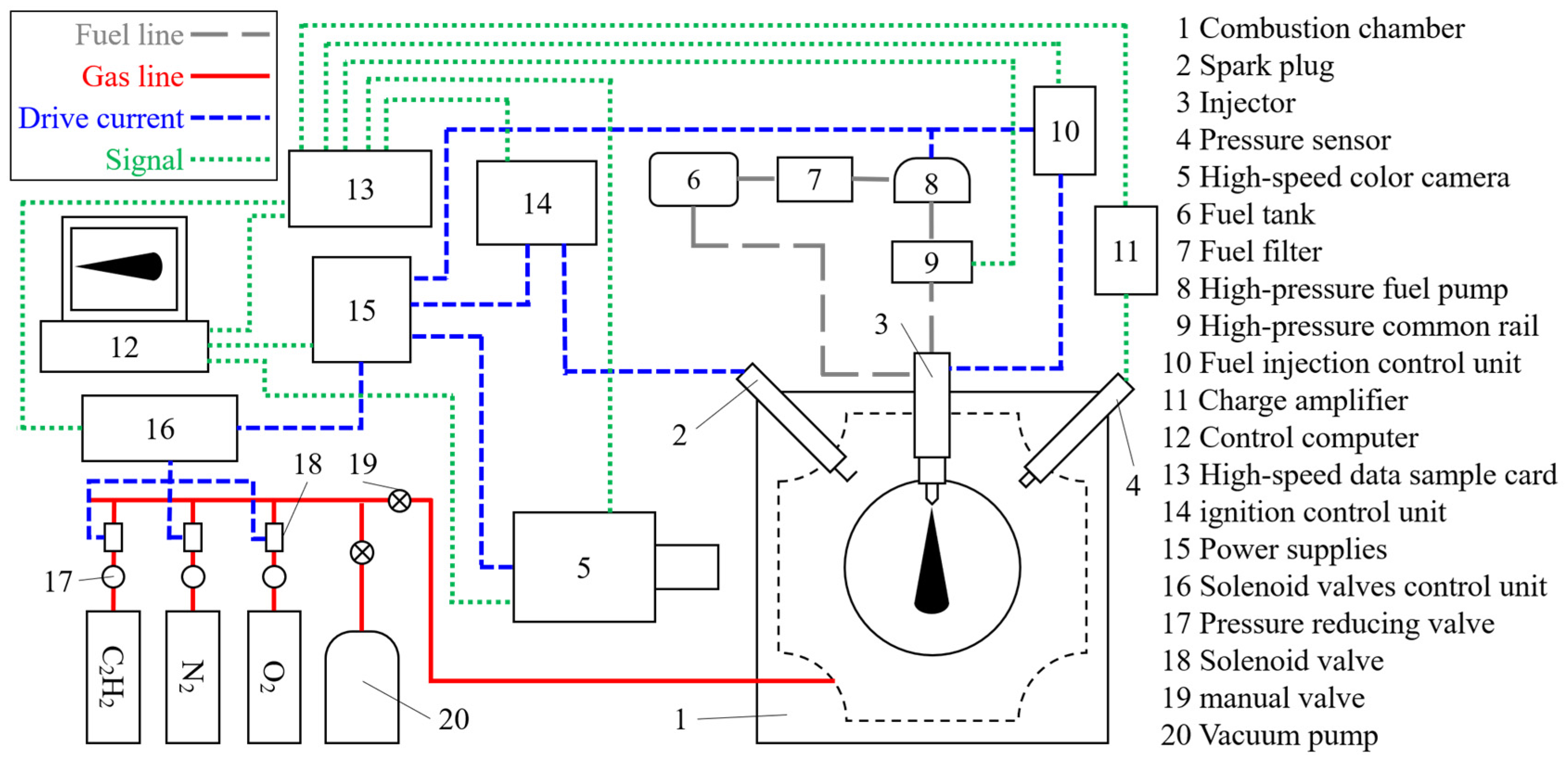
2. Experimental Apparatus and Procedure

2.1. Optical Chamber and Injection System

All of the visualization experiments in this investigation were performed in a CVCC. A schematic diagram of the system is shown in Figure 1. By means of the pre-combustion technique, the CVCC was able to mimic the target conditions at pressures and temperatures representative of those prior to injection in a heavy-duty diesel engine operated under different altitude conditions. The major structure of the CVCC was a symmetric cube with a length of 380 mm, and inside the CVCC, there was a closed cubical combustion chamber with a length of 136 mm. This means that the distance from the injector tip to the end wall of the chamber was 136 mm, which satisfied the requirement for fully developed spray-combustion studies of a free jet. In addition, the CVCC had six main ports for optical access or injector installation. Two quartz windows with a maximum optical diameter of 130 mm and a thickness of 50 mm were installed in line with the light beam to form line-of-sight optical access for visualization. For the other four ports that did not require optical access, metal blanks were installed.
A Bosch model CRIN2 fuel injector with a single sac-type nozzle located on the injector axis was mounted vertically at the center of one main metal port so that the diesel spray flame could be guided to the center of the combustion chamber. A Bosch CP3.3 fuel pump was used to pressurize the injection system, and the fuel pressure was monitored using a transducer installed on the Bosch HFRN-16 common rail. The injection duration was set to 2.0 ms in all of the tests in order to achieve a quasi-steady state of spray and flame.

2.2. Pre-Combustion Technique

This section provides a description of the pre-combustion technique, and more details can be found in previous publications [27,40]. Briefly, this technique was employed to generate a high-temperature, high-pressure environment in the combustion chamber by conducting premixed combustion of a configurable mixture charge. In order to ensure the precise control of the charging pressure and record the in-chamber pressure of the CVCC, a Kistler 6052C pressure sensor (Winterthur, Switzerland), a Kistler 5018 charge amplifier, and an NI USB-6251M high-speed data sample card were combined to form an independent pressure acquisition system. Then, the following procedure was executed to simulate engine-like conditions. Initially, three gases, acetylene (C2H2), oxygen (O2), and nitrogen (N2), were input into the CVCC sequentially via a manual valve (Figure 1) to achieve the precalculated partial pressures, forming a combustible gas mixture with a specified density. The density corresponded to the in-cylinder ambient density of the diesel engine operated under the simulated altitude conditions. Then, this mixture was ignited with a spark plug (Figure 1). By means of the pressure acquisition system, the in-chamber pressure profile from premixed combustion to spray combustion was recorded in Figure 2. When the pressure had decreased to the pre-calculated value during the cooldown stage, the diesel injector was triggered, and the fuel injection, autoignition, and combustion processes ensued, which caused the pressure to increase again (Figure 2). Moreover, the high-speed color camera was triggered simultaneously with the fuel injection to record the spray and flame images.
Two experimental environments were constructed using the pre-combustion technique to conduct the evaporation and combustion tests in this investigation. The global reaction equation for the pre-combustion process is as follows:
aC2H2 + bO2 + cN2 → dCO2 + eH2O + fO2 + gN2
The oxygen concentration could be controlled by adjusting the mixing ratio of the three gases in the reactant mixture. The coefficients of the equation for the evaporation and combustion tests are listed in Table 1. In the evaporation tests, the oxygen concentration after pre-combustion was manipulated to be 0% to prevent the fuel from the ignition, enabling visualization of the evaporating spray in the absence of combustion. In the combustion tests, the oxygen concentration was set to 21%, reproducing typical engine operation without exhaust gas recirculation (EGR), so the subsequently injected fuel autoignited and combusted rather than merely atomizing and evaporating. In addition, the concentration of C2H2 was always set to 4% in order to avoid misfiring and knocking during the premixed combustion. The coefficients in Equation (1) were also used in the calculation of the partial pressures of the three charge gases.

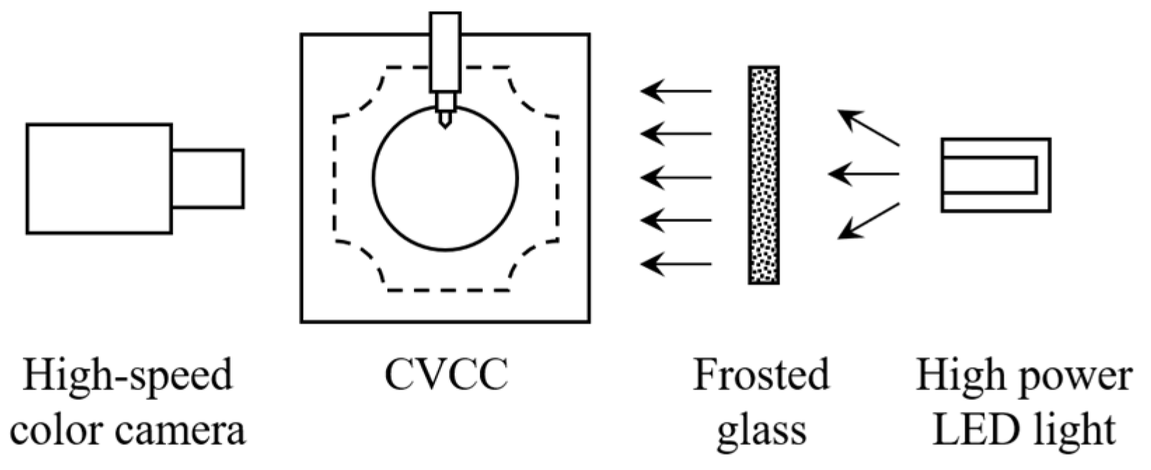
2.3. Optical Techniques and Processing Methods

Three standard optical techniques were employed to visualize the liquid spray, ignition, and combustion flame separately. The camera settings for the three techniques are listed in Table 2. The corresponding optical arrangements and image processing methods are described in detail below.

2.3.1. Visualization of Liquid Spray Penetration

Diffused back-illumination imaging (DBI) can be used to recognize the liquid spray phase from the silhouette obtained by the obstruction of a beam of diffused light by the jet [41]. Because it is less sensitive to the experimental setup, such as the intensity and position of the illumination source, DBI is recommended by the ECN as the standard technique for liquid boundary detection of a vaporizing spray [42]. The optical arrangement for DBI employed in this investigation is illustrated in Figure 3. A 40-W high-power light-emitting diode (LED) light was used as the illumination source. The light passed through a piece of frosted glass to turn it into a diffused bundle of rays, which then went through the CVCC and were directly collected by a high-speed color camera. Finally, spray images with a homogenized background were acquired.
Figure 4 presents the processing sequence of the acquired DBI images, and the corresponding steps are described below:
  • Step 1: Background subtraction. In order to eliminate environmental disturbances in subsequent spray images, the background image, which was regarded as the frame right before the fuel injection, was subtracted arithmetically from the raw images;
  • Step 2: Liquid boundary detection. After the background subtraction, a threshold was carefully selected for image binarization to optimally determine the boundary of the liquid spray. This means that only the pixels connected to the center of mass of the spray were conserved while avoiding underestimation of the liquid boundary;
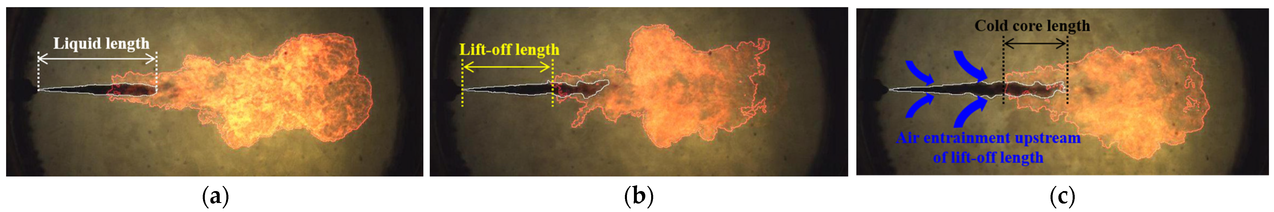
  • Step 3: Contour analysis. Once the liquid boundary was determined, several interesting macroscopic parameters, including the liquid phase penetration and liquid length, were calculated to characterize the liquid spray process. The liquid phase penetration is defined as the distance from the injector tip to the most downstream of the detected boundary. During the quasi-steady period, the average of the liquid phase penetration is referred to as the liquid length.
Figure 4. Image processing sequence for liquid boundary detection. (a) Raw image; (b) Background image; (c) Binary image; (d) Determined boundary.
Energies 16 04832 g004

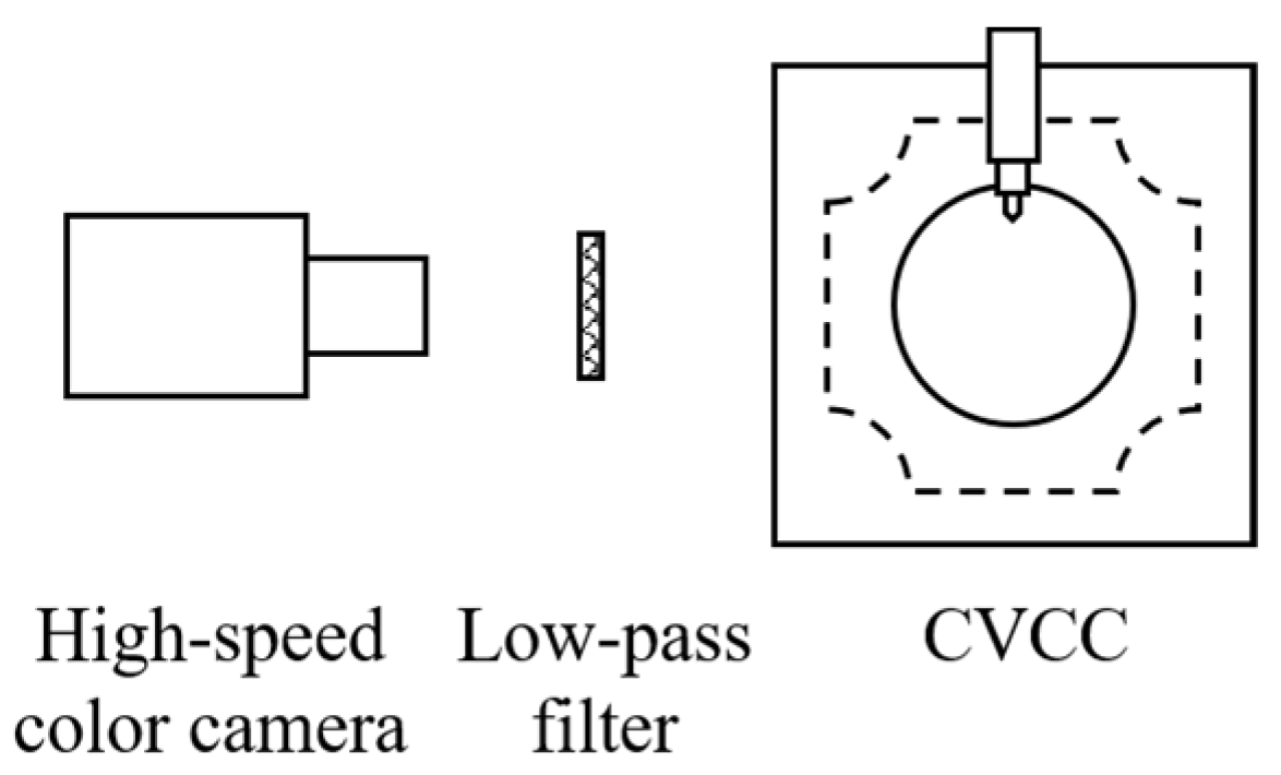
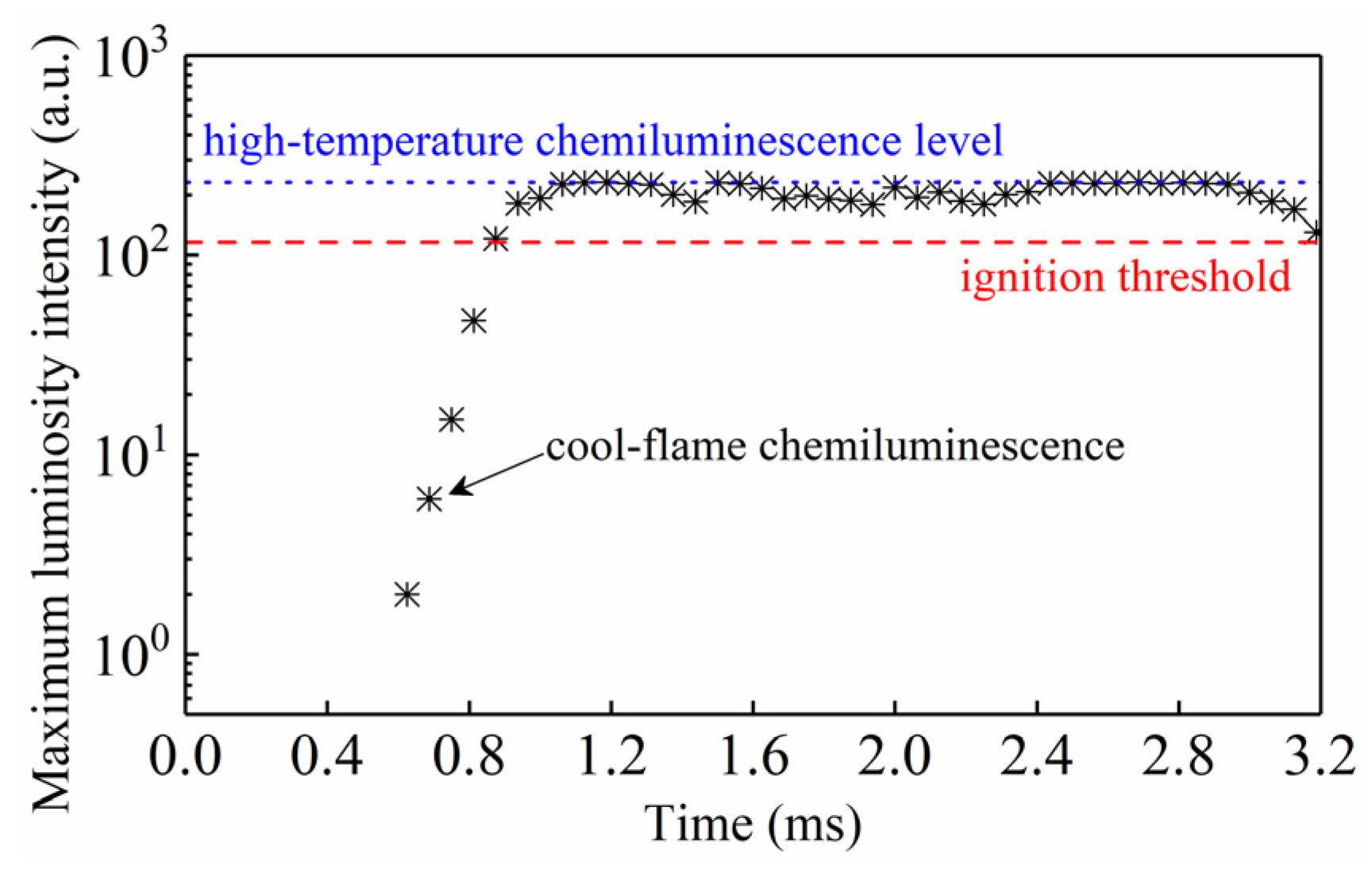
2.3.2. Visualization of High-Temperature Ignition Process

Previous studies [43,44,45] confirmed that diesel ignition is strictly linked with chemiluminescence emissions during combustion. Because of this, broadband chemiluminescence imaging, introduced by Lillo et al. [44], was proven to be feasible for directly measuring the timing and location of spray ignition due to the ability to detect a large range of chemiluminescent species that appear at the onset of high-temperature ignition. Figure 5 illustrates the optical arrangement. A 600-nm low-pass filter was used to reject the higher wavelength thermal emissions from the reaction species and subsequent soot incandescence while being allowed the collection of other radicals (e.g., CH* and C2*).
For the acquired ignition images, a standard processing methodology was developed in related studies [27,43,44]. Initially, a region of interest near the expected lift-off length (or far from the soot luminosity) should be virtually drawn. Then, the maximum intensity calculated in this area can be plotted versus time (Figure 6). The intensity increases by several orders of magnitude from the weak chemiluminescence of a cool flame to an intense glow, and the latter stabilizes at a certain level, which is defined as the high-temperature chemiluminescence level. Following the recommendation of the ECN, the ignition threshold was fixed at 50% of the magnitude of the high-temperature chemiluminescence level. The moment when the chemiluminescence exceeded the ignition threshold was defined as the moment of ignition, and the duration from the start of injection to this moment is defined as the ignition delay. The ignition distance is defined as the axial distance from the injector tip to the location where the high-temperature chemiluminescence emerged.

2.3.3. Visualization of Combustion Flame Propagation

Spectroscopic studies associated with hydrocarbon flames have confirmed that the natural luminosity of a flame during combustion mainly includes the chemiluminescence of intermediate species radicals and the incandescence of soot, and the latter is several orders of magnitude stronger than the former [34,46,47]. Hence, it is accepted that the natural flame luminosity can not only directly reflect the geometric shape of the combustion flame but also the soot formation information to some extent. Therefore, flame natural luminosity imaging has been widely used in recent spray-combustion studies due to its simplicity and explicitness [40,48,49]. The optical arrangement was similar to that for DBI (Figure 3), except that an ND8 filter was used in place of a low-pass filter to reduce the brightness of the flame to 1/8 of its original value in order to avoid camera sensor saturation.
The flame images were processed in a similar way to the DBI images, and choosing an appropriate threshold was also key for flame boundary detection. Based on the identified contour, a number of parameters can be used to characterize the flame geometry and soot formation characteristics mentioned above. The parameters relevant to this investigation are as follows:
  • Flame lift-off length: As an important controlling parameter in the fuel–air mixing prior to the combustion region, the flame lift-off length is defined as the distance from the injector tip to the most upstream location of the flame contour;
  • Flame area: The flame area was calculated by multiplying the pixel area by the number of pixels within the flame boundary to reflect the spatial distribution of the flame.
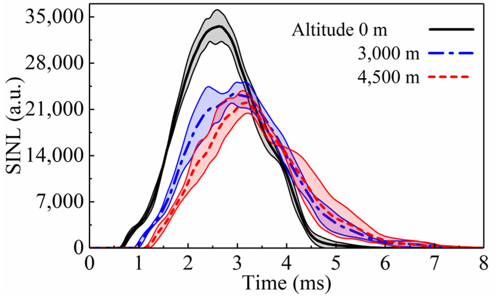
  • Spatially integrated natural luminosity (SINL): By summing up the intensity values of all the pixels inside the flame boundary of each flame image, the SINL is obtained to represent the instantaneous intensity of the natural luminosity of the flame;
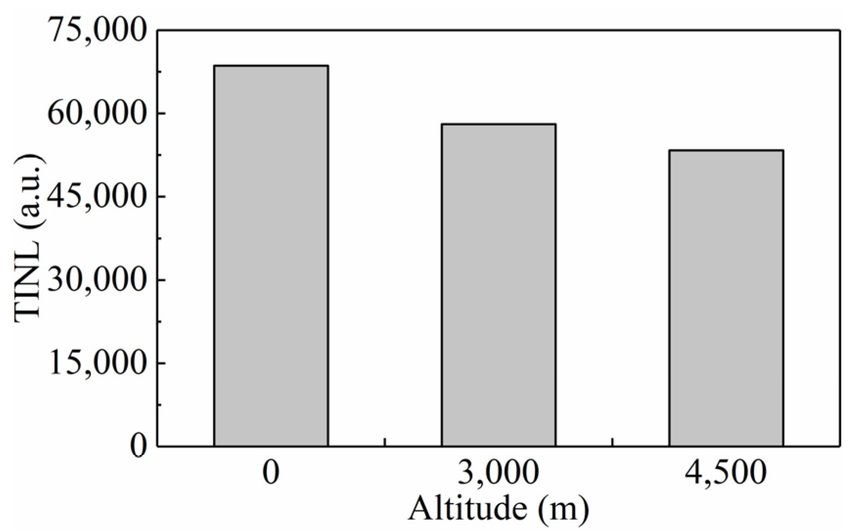
  • Time-integrated natural luminosity (TINL): The TINL is calculated by integrating the SINL with time to quantify the natural luminosity over the entire combustion duration.

2.4. Experimental Conditions

The detailed experimental conditions are listed in Table 3, which were determined based on a real heavy-duty intercooled–turbocharged diesel engine with a compression ratio of 14.25. By means of the pre-combustion technique described in Section 2.2, the in-cylinder thermodynamic conditions of a prototype engine at the start of fuel injection when operating under the altitude conditions of 0, 3000, and 4500 m were reproduced in the CVCC. Both the ambient pressure and ambient temperature are influenced by the altitude. However, environmental pressure was previously confirmed to be the main factor [50]. Moreover, the intake temperature after the inter-cooler was maintained at 353 K, regardless of the altitude, based on the prototype engine. Consequently, it is reasonable to characterize the simulated altitude solely in terms of the ambient density. The nozzle diameter of the fuel injector was 0.32 mm, and the injection pressure was set to 90 MPa to mimic realistic scenarios of the prototype engine. In addition, each test condition was repeated at least five times to ensure experimental reliability and repeatability.

3. Results and Discussion

3.1. Liquid Spray Characteristics

3.1.1. Liquid Spray Morphology

Figure 7 presents the evolution of the liquid spray under the altitude conditions of 0, 3000, and 4500 m. Intuitively, the evolution for all of the altitudes should exhibit typical diesel spray behavior under engine-like thermodynamic conditions [51]. Initially, the liquid fuel penetrated quickly, and the concentration of the liquid phase was large, mainly due to the restricted atomization. Then, as it penetrated further, the fuel evaporated quickly due to the continuous breakup of droplets and entrainment of hot ambient gas, and thus, the concentration gradient of the liquid phase at the liquid spray tip became more progressive. Eventually, the liquid fuel evaporated completely, so the liquid spray stopped penetrating further beyond a certain distance downstream even though the fuel injection continued, indicating that the liquid spray had fully developed in the CVCC.
Additionally, it is important to note, in particular, that the atomization and evaporation processes evolved gradually, and there was no distinct boundary between the liquid and vapor phases, which is consistent with previous observations [52,53]. Thus, as was described in Section 2.3.1, a threshold should be carefully selected to determine the boundary of the liquid spray, and only then could the liquid phase penetration and the liquid length be accurately calculated as macroscopic parameters for quantifying the liquid spray morphology.

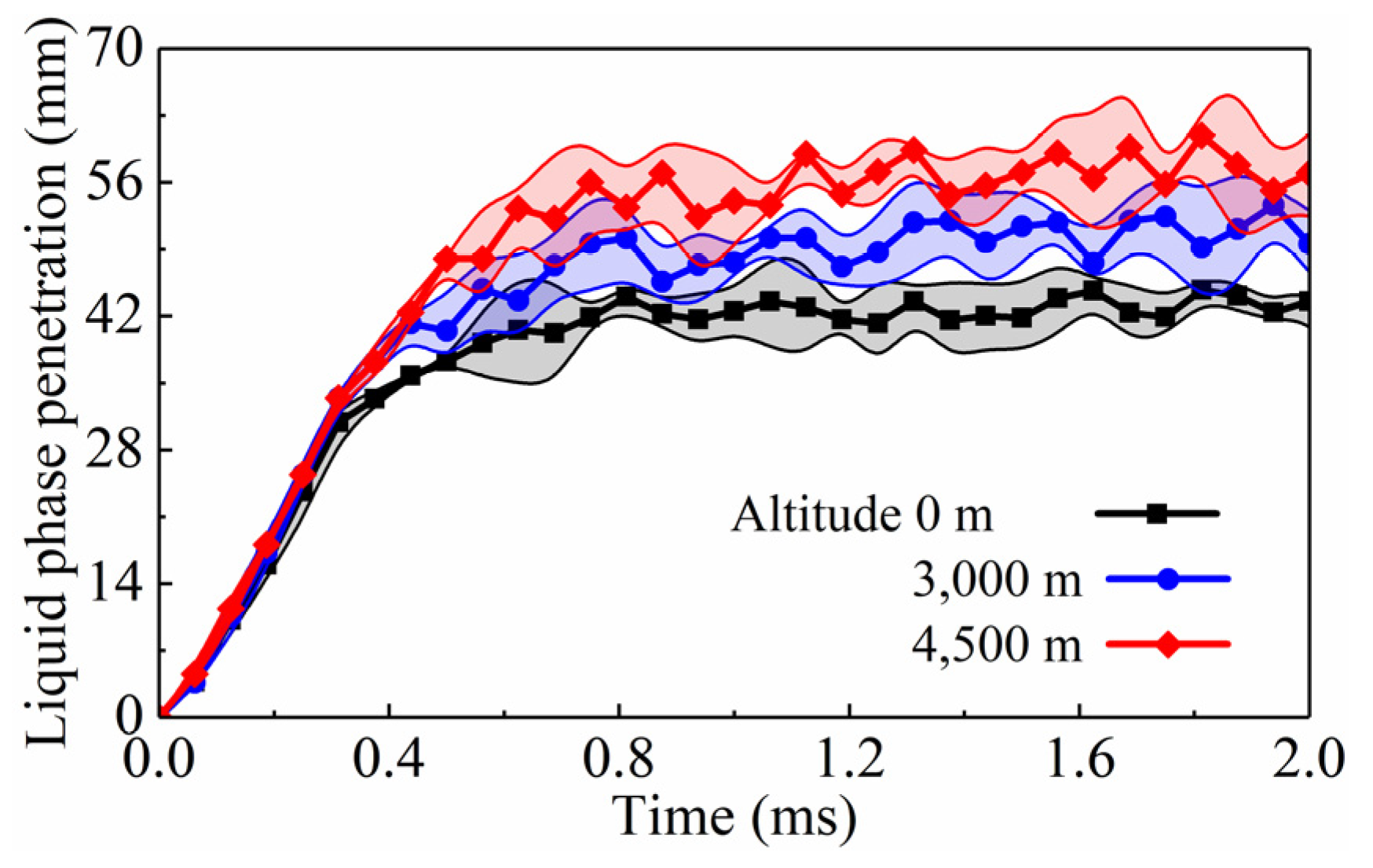
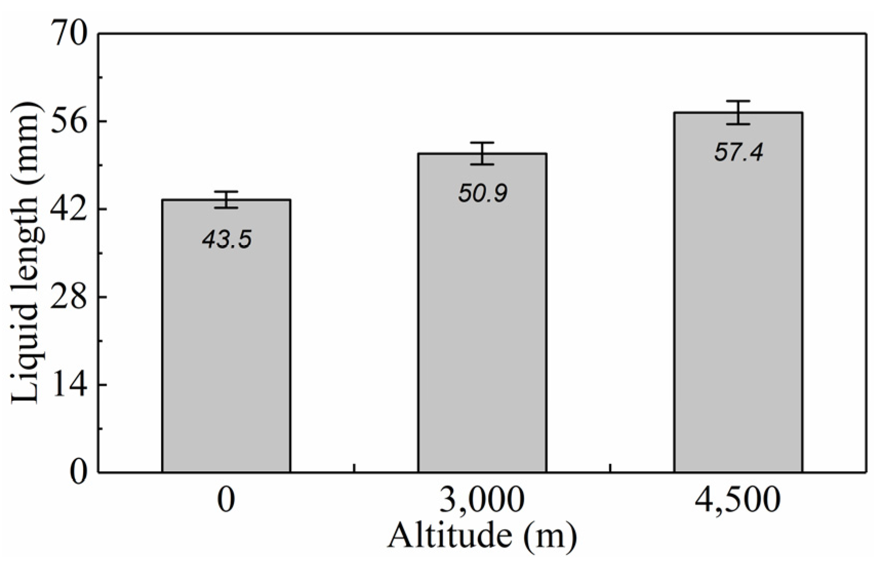
3.1.2. Liquid-Phase Penetration and Liquid Length

A plot of the liquid-phase penetration versus time under the altitude conditions of 0, 3000, and 4500 m is shown in Figure 8. The error bars denote the standard deviation (also in the following figures). In the initial development period, the liquid spray penetrated almost linearly, and the curves for all of the altitudes virtually overlapped, which may have been mainly because, during this period, the predominant injection momentum remained unchanged due to the identical injection pressure, regardless of the altitude. As time proceeded, a point was reached where the curve broke over, and thereafter, the spray tip fluctuated around a fixed axial location, meaning that the liquid spray development had shifted to a quasi-steady period. During this stage, it is clear that the ambient gas resistance, instead of the injection momentum, played a dominant role in the spray penetration, which was totally different from the initial development period.
In other words, the altitude significantly influences spray penetration in the quasi-steady period. For this reason, it is necessary to compare the liquid length under different altitude conditions, as shown in Figure 9. The liquid lengths were calculated to be 42.8, 50.9, and 57.4 mm for the altitudes of 0, 3000, and 4500 m separately. This positive correlation with altitude was expected because the lower ambient density induced by the higher altitude significantly slowed the vaporization rate of the liquid fuel by reducing both the droplet breakup rate and the amount of air entrained into the liquid spray [54].
It should be noted that the variation in altitude was characterized by the change in the ambient density in this investigation. Although the available literature has reported on the effect of the ambient density on liquid spray characteristics [51,54,55], the results described above are essential because they confirm the reliability of the DBI method employed in this investigation and supply robust data on the liquid length under different altitude conditions for deeper analysis in the following sections.

3.2. Ignition Characteristics

3.2.1. Ignition Morphology

The time sequences of the broadband chemiluminescence images recording the high-temperature ignition processes under the altitude conditions of 0, 3000, and 4500 m are presented in Figure 10. In order to visualize the entire ignition process from 0 to 4500 m, the displayed sequences began slightly prior to the appearance of chemiluminescence under the altitude condition of 0 m and ended shortly after the occurrence of ignition under the condition of 4500 m. Concurrent with the fuel injection, the spray in the CVCC underwent breakup, vaporization, and entrainment with the hot ambient gas to form a richer mixture. After further fuel–air mixing, the mixture became lean and then started emitting very weak chemiluminescence from a series of chemical reactions in the low-temperature range. Therefore, this emission was low-temperature or cool-flame chemiluminescence [27,44,56]. As the low-temperature reactions kept releasing heat and continuously accumulating radicals, the chemiluminescence became strong, i.e., high-temperature chemiluminescence [27,44]. Following the convention described in Section 2.3.2, the high-temperature ignition was determined, and the ignition kernels are annotated in Figure 10. As the occurrence of high-temperature ignition was delayed when the altitude was increased from 0 to 4500 m, it was qualitatively concluded that higher altitudes had a distinct inhibitory effect on the ignition. For a more in-depth understanding, several typical metrics of the ignition morphology and the spatial distribution of the ignition kernels are discussed quantitatively.

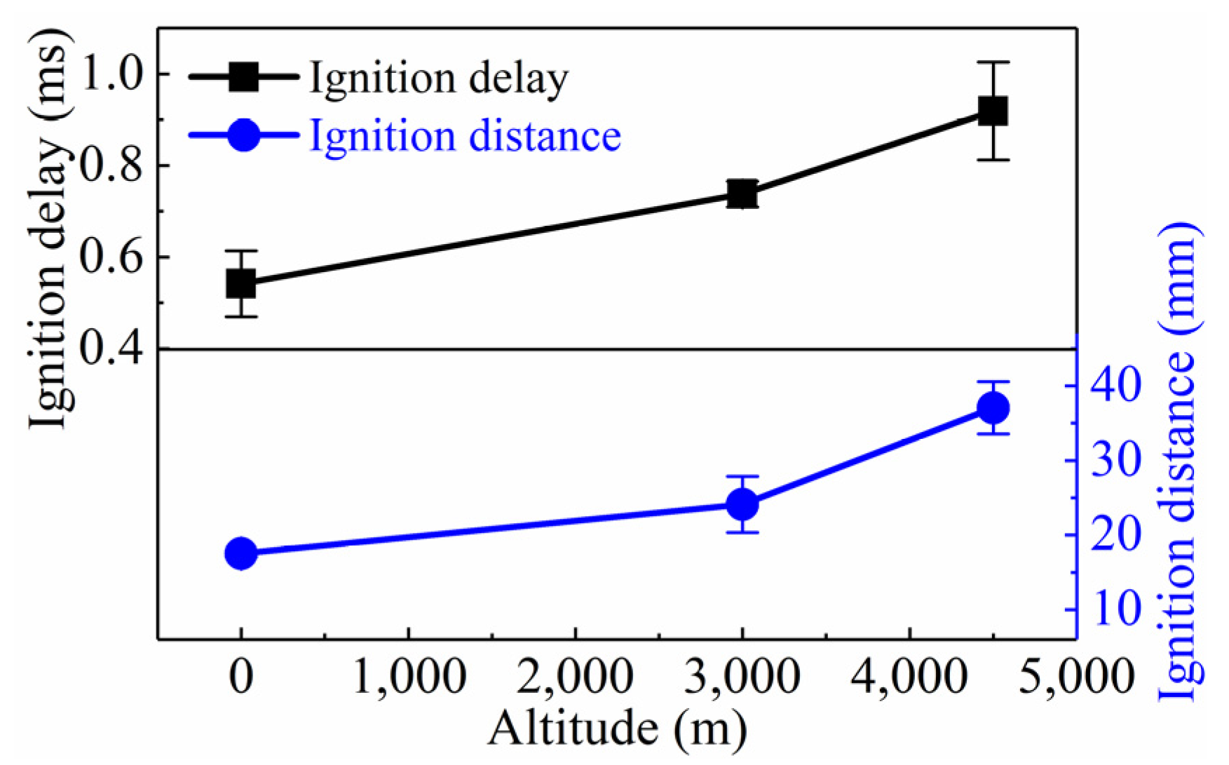
3.2.2. Ignition Delay and Ignition Distance

As shown in Figure 11, when the altitude was increased from 0 to 4500 m, the ignition delay increased from 0.54 to 0.92 ms, and the ignition distance increased from 17.5 to 37.0 mm. Thus, the higher altitude prolonged the ignition delay and lengthened the ignition distance, demonstrating both spatial and temporal inhibitory effects. This can be explained by the fact that with increasing altitude, the ambient density decreased, which weakened fuel–air mixing dynamics, thereby resulting in a higher equivalence ratio [57], so it took the spray more time to mix and, at the same time, it penetrated further downstream to entrain more ambient gas in order to make the fuel–air mixture suitable for ignition.

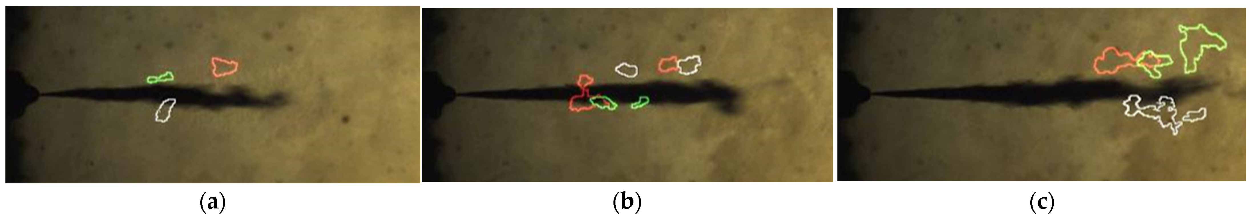
3.2.3. Spatial Distribution of Ignition Kernels

It is well-known that diesel spray exhibits a type of intrinsically stochastic behavior driven by high momentum and high turbulence under high-temperature and high-pressure conditions. Consequently, the ignition process has been found to be highly stochastic [44,58]. One manifestation of this is the variations in the locations and shapes of the ignition kernels annotated in Figure 10. This section discusses the spatial distribution of the ignition kernels under different altitude conditions to further clarify the effect of altitude on the ignition characteristics.
To this end, broadband chemiluminescence images from three repetitions under identical altitude conditions were selected, and then, the borders of all of the ignition kernels were drawn as white, red, and green lines. Next, all of the colored borders were superimposed onto one image and overlaid with the liquid spray image taken at the same time. This culminated in the spatial distributions of the ignition kernels under different altitude conditions, as shown in Figure 12. At first glance, the ignition kernels of the three repetitions under each altitude condition presented an irregular spatial pattern and did not coincide with each other, which verified the inherently stochastic behavior of the ignition process, especially under higher altitude conditions. Furthermore, it was found that the ignition kernels were mainly distributed at the outer periphery of the liquid spray, away from the centerline. This observation can be explained as follows. The eddy structures, which formed and shed along the periphery of the spray, provided a relatively quiescent environment for the fuel–air mixing and chemical reaction without the disruptive effect of the fluid mechanics of the liquid spray [59], making the vapor mixture along the periphery of the liquid spray the most favorable for the occurrence of autoignition.
Another interesting observation from Figure 12 is that the ignition occurred at multiple sites simultaneously, and the projected area generally increased as the altitude increased. To quantify this trend, Table 4 presents the average number and area of the ignition kernels under each altitude condition shown in Figure 12. When the altitude was increased from 0 to 3000 m, the average number of the ignition kernels increased from one to two, and the average area increased from 5.0 to 10.9 mm2, which was mainly related to the inhibitory effect of the higher altitude on the ignition, demonstrating that more fuel–air mixture took part in the ignition. However, when the altitude was further increased to 4500 m, the average number of ignition kernels decreased to 1.7, and the average area increased significantly to 23.9 mm2. This could be because both the longer ignition delay and ignition distance led to more of the mixture reaching the ignitability limit almost simultaneously, and thus, the ignition under the condition of 4500 m occurred at multiple sites and then rapidly filled the space between these sites through augmentation by adjacent sites. For real diesel engines operating under higher altitude conditions, this kind of coalescence would potentially trigger pressure waves and the formation of shock waves [59], which could cause a higher peak pressure rise rate [16,19]. More refined observations should be captured by ignition models to improve their adaptability for diesel engines operating in plateau regions.

3.3. Flame Characteristics

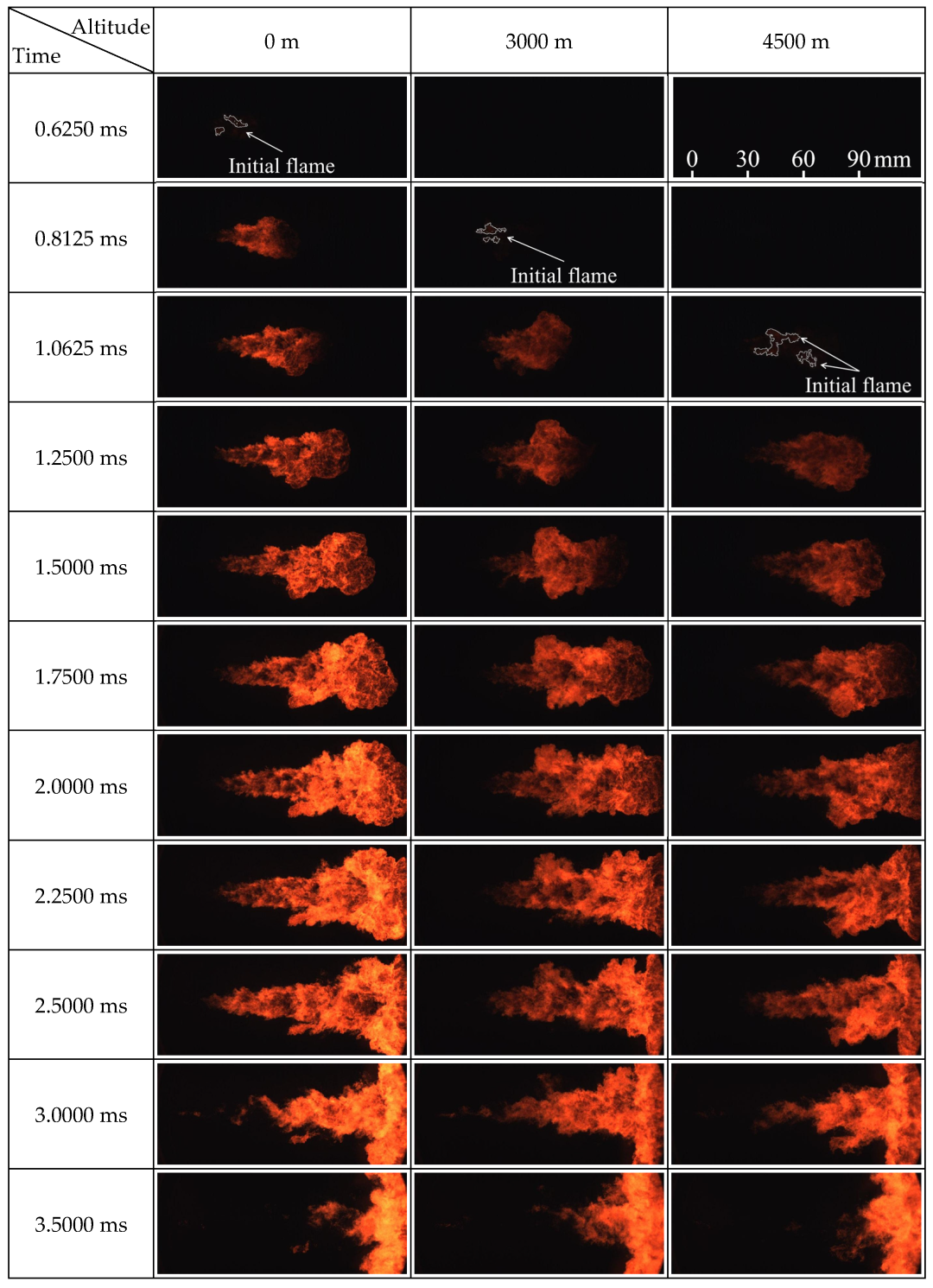
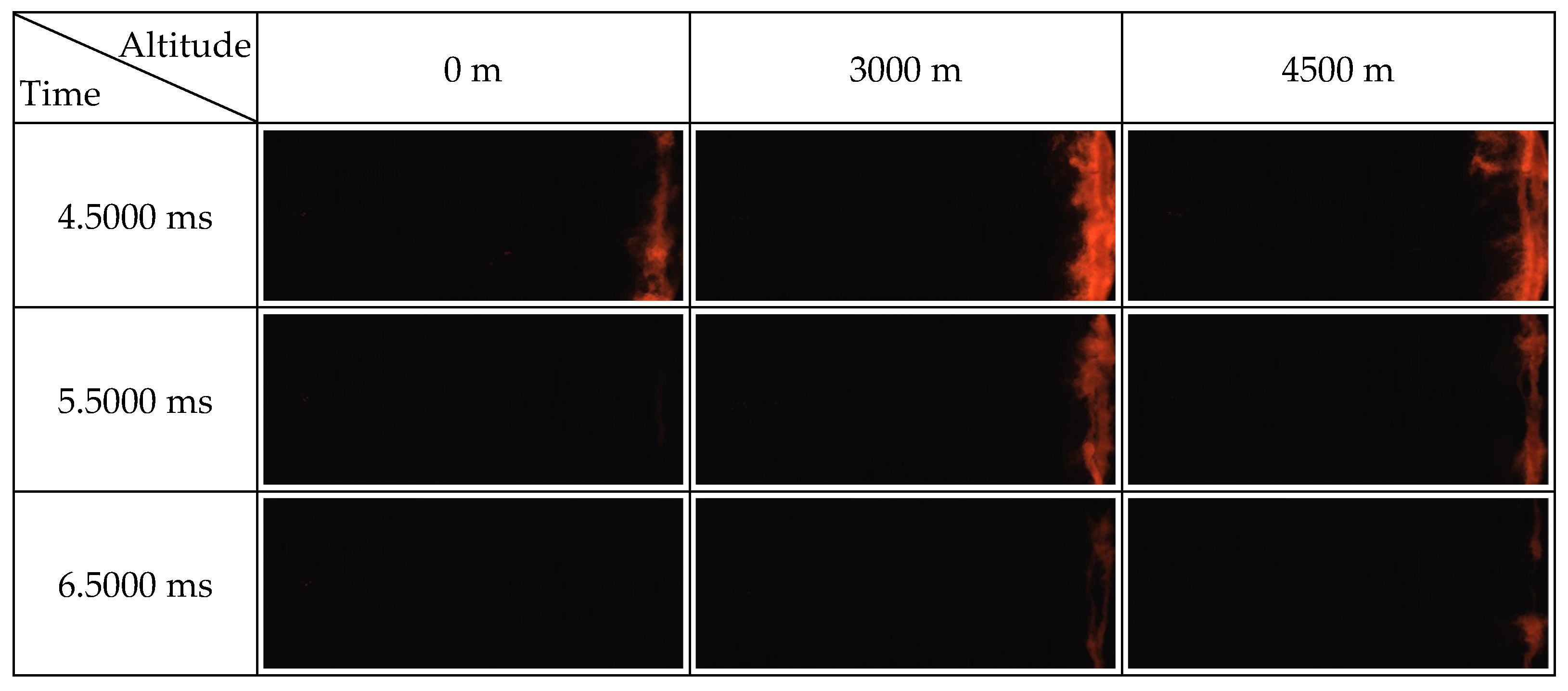
3.3.1. Flame Morphology

Figure 13 shows the evolution of the luminous flame under the altitude conditions of 0, 3000, and 4500 m. Immediately after the aforementioned high-temperature ignition, a weak natural luminosity appeared and subsequently became stronger. As the luminosity region continuously moved downward, driven by the momentum provided by the fuel injection, both the size and luminosity of the combusting flame increased due to increased soot formation. As time proceeded, the flame evolution reached a quasi-steady state, and the flame turned into a lifted, turbulent diffusion flame until the end of the injection [32], which is consistent with the conceptual model of mixing-controlled combustion proposed by Dec [28]. During this period, the flame simultaneously propagated downstream and extended upstream to a stabilized location. The flame lift-off length defined in Section 2.3.3 was calculated and will be discussed in the next section. After the end of the fuel injection, the injection momentum decreased suddenly, and much of the ambient gas was entrained, allowing the flame to exhibit a tendency to propagate back toward the maximum upstream [60]. In addition, in the downstream zone, the flame tip interacted with the end wall of the chamber for a moment and then spread out along the periphery of the chamber wall. As the luminosity region gradually became narrower, the flame contracted to the near-wall region and eventually disappeared. Overall, when the altitude was increased from 0 to 4500 m, the appearance and disappearance of the flame luminosity region were retarded, and the overall flame luminosity seemed to be dimmer.
It is interesting that the criterion for determining the occurrence of ignition employed in this work (described in Section 2.3.2) was significantly different from that employed in other studies, which adopted the appearance of the initial flame as the occurrence of ignition [37,52,61,62]. As the comparation in Figure 14 shows, the appearance of the initial flame annotated in Figure 13 apparently lagged behind, both temporally and spatially; the high-temperature ignition is annotated in Figure 10. Pertinent studies have confirmed that the combustion of diesel spray is characterized by the first onset of low-temperature ignition (first-stage ignition), followed by high-temperature ignition (second-stage ignition), and thereafter, natural luminosity appears due to soot formation [27,43,63]. Moreover, the start of the combustion pressure rise was in good agreement with the timing of the high-temperature ignition [42,44]. Thus, it can be reasonably concluded that the broadband chemiluminescence imaging method employed in this investigation provides more trustworthy ignition measurements for obtaining a high-quality ignition dataset for different altitudes.

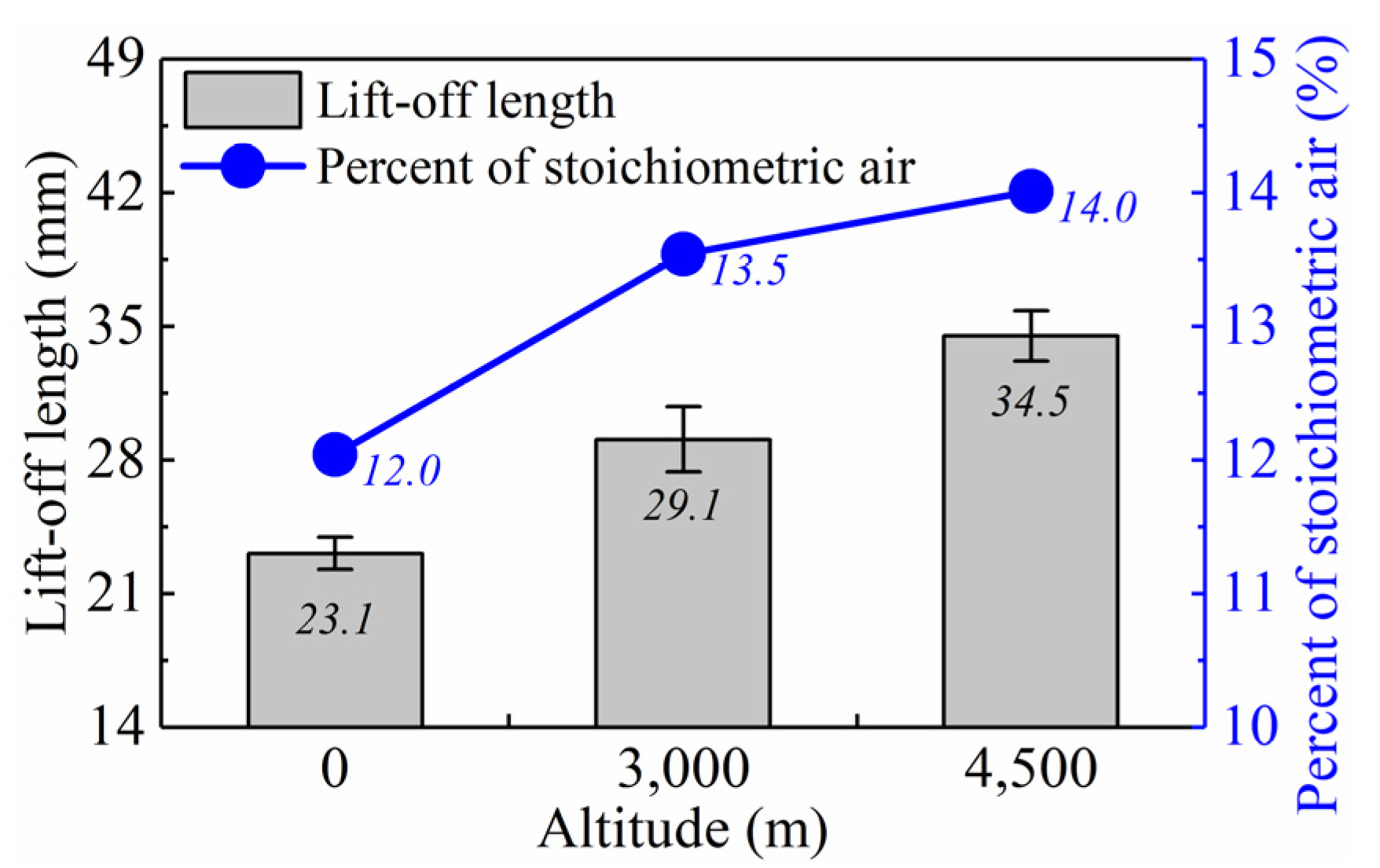
3.3.2. Flame Lift-Off Length and Air Entrainment Upstream of Lifted Flame
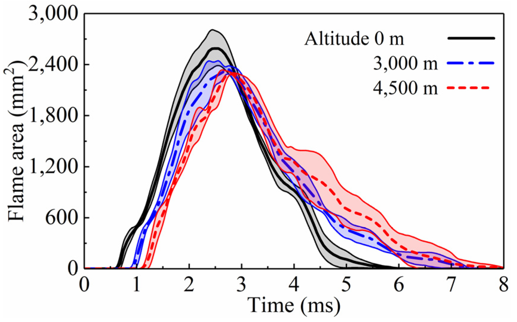
The flame lift-off lengths under the altitude conditions of 0, 3000, and 4500 m are shown in Figure 15. The lift-off length gradually increased from 23.1 to 34.5 mm as the altitude was increased from 0 to 4500 m. This was mainly related to the variation in the ignition delay [34]. The ignition was retarded under higher altitude conditions (Figure 11), and the lift-off length increased correspondingly. Moreover, based on previous knowledge [29,32,34,37], the lift-off length allowed the fuel and air to premix upstream of the lifted flame, and then, the entrained oxygen is believed to have reacted with the fuel in a rich reaction zone in the central region of the flame located downstream of the lift-off length. Thus, the amount of air entrainment upstream of the lifted flame strongly affected the combustion and soot formation processes downstream. It is interesting to identify the air entrainment upstream of the lifted flame under different altitude conditions to comprehensively consider the lower ambient density and, consequently, longer lift-off length caused by the higher altitude.
In view of this, starting from the expression for the axial variation in the cross-sectional average equivalence ratio in the spray ( ϕ ¯ ) proposed by Naber and Siebers [31], when the axial location is designated as the lift-off length, multiplying the reciprocal of the equivalence ratio relationship by 100 gives an expression for the air entrained up to the lift-off location as a percentage of the total air required to completely burn the injected fuel. This percentage has been redefined by Siebers and Higgins [32] as the percent of stoichiometric air ζ % :
ζ % = 100 / ϕ ¯ H = 100 1 + 16 H / x + 2 1 / 2 f s
where ϕ ¯ H is the equivalence ratio of the lift-off length; H is the flame of the lift-off length; x + is the characteristic length scale for the spray, and f s is the stoichiometric air–fuel ratio. The details about the parameters required to calculate ζ % have been described in the authors’ previous work [57].
As shown in Figure 15, the percent of stoichiometric air increased from 12.0% to 14.0% as the altitude increased from 0 to 4500 m. Under higher altitude conditions, the lower ambient density resulted in globally poorer fuel–air mixing [11,57], while the larger lift-off length broadened the spatial extent of the air entrainment upstream of the lifted flame and promoted local fuel–air mixing. However, the change in the percent of stoichiometric air clearly demonstrated that the net effect of the altitude was an increase in the amount of air entrained at the lift-off length, meaning that the well-accepted global deterioration of fuel–air mixing under higher altitude conditions could be locally compensated for by the longer lift-off length. As a direct consequence of the fuel–air mixing, soot formation will be discussed in Section 3.5.

3.3.3. Flame Area

The flame area reflects the spatial distribution of the flame and, thus, reveals the soot formation. Figure 16 presents the variations in the flame area with altitude. As the altitude was increased from 0 to 4500 m, the peak value of the flame area decreased, which was mainly due to the increased lift-off length. As can be seen from the flame morphology shown in Figure 13, the upstream of the lifted flame was further away from the injector; i.e., the lift length was longer, resulting in a narrower spatial distribution of the flame and, consequently, a lower peak flame area. However, in the later stage of the combustion, the lower ambient density reduced the burnout rate of the reactants under higher altitude conditions, so the curves declined more slowly.

3.4. Relationship between Diesel Vaporization and Combustion Processes

In addition to the fuel–air mixing upstream of the lift-off length discussed in the previous section, the concern that needs to be addressed in conjunction with the free spray-combustion characteristics of diesel engines operating under different altitude conditions is the relationship between the diesel vaporization and combustion processes. The comparison of the liquid length and the lift-off length could provide some insights into this relationship to some extent. The liquid spray image and flame’s natural luminosity images taken at 1.5 ms after the start of injection (ASOI) during the quasi-steady period under each altitude condition were synthesized to obtain the spatial distribution of the liquid region and flame region under different altitude conditions. In Figure 17, the white solid lines denote the liquid spray region; the liquid length is annotated in white; the solid red lines denote the flame region, and the lift-off length is annotated in red.
At first glance, the liquid length was always greater than the lift-off length for each altitude, and thus, there was overlap between the liquid fuel and combustion flame, resulting in the appearance of a so-called cold core [53] inside the diffusion flame sheath. The cold core length, which is the distance from the most upstream of the flame to the end of the liquid region (annotated in black in Figure 17), was calculated as the difference between the liquid length and the lift-off length. The calculated cold core lengths were 20.4, 21.8, and 22.9 mm under the altitude conditions of 0, 3000, and 4500 m, respectively. This moderately increasing trend can be explained by means of a scaling law. The scaling of the liquid length with the ambient density is approximately ρ a 0.7 , according to Siebers [64], while the lift-off length is scaled by ρ a 0.85 , according to Pickett and Siebers [34]. This means that the liquid length has a slightly stronger dependence on the ambient density than the lift-off length. Thus, when the ambient density decreases with increasing altitude, the increase in the liquid length will be slightly greater than the increase in the lift-off length, resulting in a longer cold core length. The overlap would have a negative effect on the combustion and emission, such as limiting the air entrainment, reducing the combustion rate, and causing more soot formation [32,38,53,65], which can contribute to the deteriorated combustion under higher altitude conditions reported in the literature to some extent.

3.5. Soot Formation

3.5.1. SINL

Figure 18 presents the SINLs under the altitude conditions of 0, 3000, and 4500 m. Overall, the variations in the SINL were analogous to the variations in the flame area (Figure 16), indicating that the flame distribution had a direct impact on the SINL. After the start of combustion, the SINL increased quickly and reached the peak as time elapsed, reflecting the soot formation process. The peak SINL value decreased with increasing altitude, indicating that less soot formed during the early stage of combustion. This phenomenon can be explained by the fact that, as discussed in Section 3.3.2, there was more air entrainment upstream of the lifted flame, producing a less rich central flame reaction zone downstream of the lift-off length [30,66], which inhibited the formation of soot precursors. After reaching the peak, the SINL decreased continuously to zero, reflecting the soot oxidation process. When the altitude was increased to higher than 3000 m, the end of the SINL curves lagged behind drastically, which was because the lower ambient density under higher altitude conditions reduced the oxygen concentration, resulting in a lower soot oxidation rate.

3.5.2. TINL

Figure 19 shows the TINLs under the altitude conditions of 0, 3000, and 4500 m. The TINL decreased with increasing altitude, indicating a lower soot formation level throughout the entire combustion duration. This can also be mainly attributed to the improved fuel–air mixing quality upstream of the lifted flame as a result of the longer lift-off length and higher percent of stoichiometric air under higher altitude conditions. Generally, based on the analysis of the SINL and TINL under different altitude conditions, it was concluded that the amount of air entrainment upstream of the lifted flame controlled the sooting tendency of the free spray combustion, which was consistent with the results of the previous studies [29,30,32,38,53,62].
Next, we seek to elucidate a noteworthy contradictory finding to improve our understanding of free spray-combustion processes under different altitude conditions. In this work, based on the natural luminosity of the free flame in the CVCC, both the SINL and TINL decreased with increasing altitude, implying a decrease in the soot formation level. In contrast, virtually all the emissions measurements for realistic diesel engines conducted in both bench tests [12,22] and on-vehicle tests [13,67] under different altitude conditions agreed that the exhaust soot concentration increases with increasing altitude. Our best explanation for these contradictory conclusions is as follows. As the diesel fuel injected was completely combusted in the closed cubic combustion chamber of the CVCC, pockets of soot were oxidized, even though the rate of soot oxidation during the late combustion period decreased with increasing altitude. However, when extrapolated to experiments conducted using real diesel engines operating in plateau regions, the soot particles formed in the combustion chamber did not have sufficient time to be oxidized before the exhaust valve opened [30], and hence, more soot survived in the final soot emissions from the engine tailpipe, which was the most visible sign of incomplete combustion under higher altitude conditions [14,19]. That is, the engine-out soot measurements essentially correlated with the luminosity intensity of the flame images during the late combustion period, which has been confirmed in previous studies [30,68]. According to this explanation, accelerating the soot oxidation process could effectively reduce engine soot emissions in plateau regions.

4. Role of Altitude in Spray-Combustion Process of Free Diesel Jet

As discussed in the preceding sections, several general features related to the free spray combustion of a diesel jet, including the liquid length, flame lift-off length, air entrainment upstream of the lifted flame, and natural flame luminosity, including the SINL and TINL, are all significantly affected by altitude, demonstrating the necessity to include the altitude as a key parameter in the practical design of diesel engines. For the heavy-duty diesel engine prototypes targeted in this investigation, in order to fully exploit their potential and improve the combustion and emissions when operating under different altitude conditions, a thorough understanding of the in-cylinder phenomena is critical. However, one important prerequisite for this understanding is a clear picture of how the spray combustion proceeds [28]. To this end, because the combined results of the visualizations presented in the preceding sections have provided a detailed understanding of the spatiotemporal evolution of the free spray combustion for a reacting diesel jet under different altitude conditions, in this section, we add complementary information about the altitude to the schematic diagram proposed by Siebers and Higgins [32]. Figure 20 schematically depicts the spray flame structure of a free jet under different altitude conditions for quasi-steady diesel combustion. The bottom-most schematic with summarized results for an altitude of 0 m is representative of the plain conditions, while the top-most schematic based on the summarized results for a 4500-m altitude represents the plateau conditions, illustrating the evolution of the free spray flame with increasing altitude. It is important to point out that the schematic presented in Figure 20 only applies to the injection parameters and boundary conditions based on the technological level of the prototype engine targeted in this investigation, and the evolution may be different from that described herein for other technological levels.
Based on the schematic diagram, the detrimental effects of higher altitudes on the combustion and emissions can be partially explained, thereby providing a phenomenological description of the role of altitude in the spray-combustion process for a free diesel jet. As shown in Figure 20, as the altitude increases, the liquid length increases, and the vaporization and mixing become correspondingly weaker. Although both the lift-off length and the percent of stoichiometric air increase, the amount of entrained air upstream of the lifted flame is not sufficient to substantially reduce the formation of soot precursors, thus making it difficult for the low ambient density under higher altitude conditions to rapidly and completely oxidize the soot particles. The cold core length, that is, the overlap between the liquid fuel and combustion flame, increases, which is a potential cause of the deterioration of the combustion and emissions [32,65].
The schematic is also helpful in explaining and validating approaches suggested to improve the performances of high-altitude diesel engines in numerous previous [11,16,69] and future studies. For example, in the optimization of injection systems, increasing the injection pressure and decreasing the nozzle orifice diameter have always been the mainstream measures. Theoretically, the lift-off length is very sensitive to the injection pressure, and the reduction in the amount of soot with increasing injection pressure is mainly due to the enhancement of the spray atomization. Downsizing the nozzle diameter significantly reduces the liquid length and improves the air entrainment to reduce the amount of soot. Nishida et al. [38] further revealed that the combination of these two measures avoids the interference of the lift-off length and liquid length, leading to a reduction in the soot formation. However, when it comes to the practice of improving the performances of diesel engines in plateau regions, the situation becomes complex. For instance, downsizing the nozzle orifice diameter causes some unexpected issues. The spray penetration, a critical factor in the emissions from heavy-duty diesel engines [70], decreases as the size of the nozzle hole decreases, narrowing the spatial distribution of the diesel spray, which is unfavorable for utilizing in-cylinder air under higher altitude conditions. However, the injector flow area also decreases, and thus, some compensation measures, such as increasing the number of orifices and/or the injection pressure, have to be implemented to ensure the critical peak load capability for heavy-duty diesel engines. Unfortunately, these changes increase the risk of jet interactions with adjacent jets and/or cylinder walls, and these phenomena are not involved in the description of a free jet in Figure 20, so practical injection system solutions for high-altitude diesel engines may be much more complicated than those deduced theoretically. In this sense, the advancement of diesel combustion technology based on the knowledge of the role of altitude determined in this work is far from complete.

5. Conclusions and Remarks

In this work, the free spray-combustion evolution of heavy-duty diesel engines operating under different altitude conditions was elaborately investigated in a constant volume combustion chamber. The conclusions from the results are summarized as follows:
  • As the altitude was increased from 0 to 4500 m, as expected, the specific parameters characterizing the free spray combustion, including the liquid length, ignition delay, ignition distance, and flame lift-off length, all monotonically increased, which was mainly due to the lower ambient density;
  • By superimposing the liquid spray and ignition images, the spatial distributions of the ignition kernels under different altitude conditions verified the inherently stochastic behavior of the ignition, especially under higher altitude conditions. Moreover, the statistical analysis of the number and area of ignition kernels provided direct evidence of greater peak pressure rise rates in high-altitude diesel engines;
  • By superimposing the liquid spray and flame images, the relationship between the diesel vaporization and combustion process under different altitude conditions was clearly identified. Because the liquid length had a slightly stronger dependence on the ambient density than the lift-off length, the length of the cold core inside the diffusion flame sheath increased slightly from 20.4 to 22.9 mm as the altitude was increased from 0 to 4500 m, which potentially contributed to the deteriorated combustion under higher altitude conditions;
  • Because a higher altitude resulted in both a lower ambient density and a longer lift-off length, the percent of stoichiometric air was calculated to increase from 12.0% to 14.0% when the altitude was increased from 0 to 4500 m, confirming that the net effect of the increasing altitude was an increase in the amount of air entrained upstream of the lifted flame;
  • Due to the improved fuel–air mixing quality upstream of the lifted flame, the peak SINL and TINL decreased, indicating a lower soot formation level with increasing altitude. However, this trend was inconsistent with the increase in the exhaust soot emissions from realistic diesel engines with increasing altitude. This is presumably due to the insufficient time for soot oxidization to occur before the exhaust valve opens, emphasizing the importance of enhancing the soot oxidation to decrease the engine soot emissions in the plateau regions;
  • A novel schematic diagram depicting the spray flame structure of a free jet under different altitude conditions was proposed to provide a phenomenological description of the role of altitude in the free spray-combustion process and to explain and validate approaches for improving the performances of high-altitude diesel engines.
It should be noted that because of the focus on and interest in the basic physics of the complex spray-combustion process, the simple assumption that the diesel jet was fully developed in an unlimited domain was made in this work, without jet interactions with adjacent jets and/or the cylinder walls. This reproduced the basic features of the free spray-combustion process well under relatively quiescent thermodynamic conditions representative of those in the prototype diesel engine operating under different altitude conditions, providing a foundation for understanding how in-cylinder spray combustion proceeds in high-altitude engines. However, there are some obstacles when extrapolating these conclusions to actual diesel engine scenarios. The most fundamental obstacle is that the actual combustion chamber is a limited domain, resulting in wall impingement. More importantly, high-altitude conditions could increase the extent of wall interactions. This issue is beyond the scope of this paper and will be discussed in the second part of this investigation.

Author Contributions

Conceptualization, C.W. and D.L.; methodology, C.W. and P.T.; writing—original draft, C.W.; writing—review and editing, X.Q., T.W. and D.L.; funding acquisition, D.L. and R.Y.; software, C.W.; project administration, P.T. and Z.H.; visualization, C.W. and L.F.; resources, X.Q. and T.W.; supervision, X.Q., T.W. and D.L. All authors have read and agreed to the published version of the manuscript.

Funding

This research was funded by the Guangxi Science and Technology Base and Talent Project (2018AD19349).

Data Availability Statement

Not applicable.

Conflicts of Interest

The authors declare no conflict of interest.

Abbreviations

CVCCConstant Volume Combustion Chamber
ICEInternal Combustion Engine
CFDComputational Fluid Dynamics
ECNEngine Combustion Network
EGRExhaust Gas Recirculation
DBIDiffused Back-illumination Imaging
LEDLight Emitting Diode
SINLSpatially Integrated Natural Luminosity
TINLTime-Integrated Natural Luminosity
ASOIAfter Start of Injection

References

  1. Reitz, R.D.; Ogawa, H.; Payri, R.; Fansler, T.; Kokjohn, S.; Moriyoshi, Y.; Agarwal, A.K.; Arcoumanis, D.; Assanis, D.; Bae, C.; et al. IJER editorial: The future of the internal combustion engine. Int. J. Engine Res. 2020, 21, 3–10. [Google Scholar] [CrossRef] [Green Version]
  2. Reitz, R.D. Directions in internal combustion engine research. Combust. Flame 2013, 160, 1–8. [Google Scholar] [CrossRef]
  3. Kalghatgi, G. Is it really the end of internal combustion engines and petroleum in transport? Appl. Energy 2018, 225, 965–974. [Google Scholar] [CrossRef]
  4. Serrano, J.R.; Piqueras, P.; Abbad, A.; Tabet, R.; Bender, S.; Gómez, J. Impact on reduction of pollutant emissions from passenger cars when replacing Euro 4 with Euro 6d diesel engines considering the altitude influence. Energies 2019, 12, 1278. [Google Scholar] [CrossRef] [Green Version]
  5. Giraldo, M.; Huertas, J.I. Real emissions, driving patterns and fuel consumption of in-use diesel buses operating at high altitude. Transp. Res. Part D Transp. Environ. 2019, 77, 21–36. [Google Scholar] [CrossRef]
  6. Liu, J.; Ge, Y.; Wang, X.; Hao, L.; Tan, J.; Peng, Z.; Zhang, C.; Gong, H.; Huang, Y. On-board measurement of particle numbers and their size distribution from a light-duty diesel vehicle: Influences of VSP and altitude. J. Environ. Sci. 2017, 57, 238–248. [Google Scholar] [CrossRef]
  7. Bermúdez, V.; Serrano, J.R.; Piqueras, P.; Gómez, J.; Bender, S. Analysis of the role of altitude on diesel engine performance and emissions using an atmosphere simulator. Int. J. Engine Res. 2017, 18, 105–117. [Google Scholar] [CrossRef]
  8. Dennis, J.W. Turbocharged Diesel Engine Performance at Altitude; SAE International: Warrendale, PA, USA, 1971; pp. 2670–2689. [Google Scholar]
  9. Husaboe, T.D.; Polanka, M.D.; Rittenhouse, J.A.; Litke, P.J.; Hoke, J.L. Dependence of Small Internal Combustion Engine’s Performance on Altitude. J. Propuls. Power 2014, 30, 1328–1333. [Google Scholar] [CrossRef]
  10. Liu, S.; Shen, L.; Bi, Y.; Lei, J. Effects of altitude and fuel oxygen content on the performance of a high pressure common rail diesel engine. Fuel 2014, 118, 243–249. [Google Scholar] [CrossRef]
  11. Wang, X.; Ge, Y.; Yu, L.; Feng, X. Effects of altitude on the thermal efficiency of a heavy-duty diesel engine. Energy 2013, 59, 543–548. [Google Scholar] [CrossRef]
  12. He, C.; Ge, Y.; Ma, C.; Tan, J.; Liu, Z.; Wang, C.; Yu, L.; Ding, Y. Emission characteristics of a heavy-duty diesel engine at simulated high altitudes. Sci. Total Environ. 2011, 409, 3138–3143. [Google Scholar] [CrossRef]
  13. Yin, H.; Ge, Y.; Wang, X.; Yu, L.; Ji, Z.; Chen, W. Idle emission characteristics of a light-duty diesel van at various altitudes. Atmos. Environ. 2013, 70, 117–122. [Google Scholar] [CrossRef]
  14. Massuchetto, M.A.; Lodetti, J. Root cause analysis, and influence of environmental characteristics on a heavy duty diesel engine fault in high altitude. SAE Technical Paper. In Proceedings of the 23rd SAE Brasil International Congress and Display, Sao Paulo, Brazil, 30 September–2 October 2014. [Google Scholar]
  15. Lizhong, S.; Yungang, S.; Wensheng, Y.; Junding, X. Combustion Process of Diesel Engines at Regions with Different Altitude; SAE Technical Paper; SAE International: Warrendale, PA, USA, 1995. [Google Scholar]
  16. Szedlmayer, M.; Kweon CB, M. Effect of Altitude Conditions on Combustion and Performance of a Multi-Cylinder Turbocharged Direct-Injection Diesel Engine; SAE Technical Paper; SAE International: Warrendale, PA, USA, 2016. [Google Scholar]
  17. Agudelo, J.; Agudelo, A.; Pérez, J. Energy and exergy analysis of a light duty diesel engine operating at different altitudes. Rev. Fac. Ing. Univ. Antioq. 2009, 48, 45–54. [Google Scholar]
  18. Benjumea, P.; Agudelo, J.; Agudelo, A. Effect of altitude and palm oil biodiesel fuelling on the performance and combustion characteristics of a HSDI diesel engine. Fuel 2009, 88, 725–731. [Google Scholar] [CrossRef]
  19. Jiao, Y.; Liu, R.; Zhang, Z.; Yang, C.; Zhou, G.; Dong, S.; Liu, W. Comparison of combustion and emission characteristics of a diesel engine fueled with diesel and methanol-Fischer-Tropsch diesel-biodiesel-diesel blends at various altitudes. Fuel 2019, 243, 52–59. [Google Scholar] [CrossRef]
  20. Wang, X.; Ge, Y.; Yu, L.; Feng, X. Comparison of combustion characteristics and brake thermal efficiency of a heavy-duty diesel engine fueled with diesel and biodiesel at high altitude. Fuel 2013, 107, 852–858. [Google Scholar] [CrossRef]
  21. Wang, X.; Ge, Y.; Yu, L. Combustion and emission characteristics of a heavy-duty diesel engine at idle at various altitudes. SAE Int. J. Engines 2013, 6, 1145–1151. [Google Scholar] [CrossRef]
  22. Yu, L.; Ge, Y.; Tan, J.; He, C.; Wang, X.; Liu, H.; Zhao, W.; Guo, J.; Fu, G.; Feng, X.; et al. Experimental investigation of the impact of biodiesel on the combustion and emission characteristics of a heavy duty diesel engine at various altitudes. Fuel 2014, 115, 220–226. [Google Scholar] [CrossRef]
  23. Zhou, G.; Liu, R.; Dong, S.; Zhang, Z.; Lin, C. Combustion temperature characteristics of a common rail diesel engine under high altitude conditions. Trans. CSICE 2016, 34, 296–303. (In Chinese) [Google Scholar]
  24. Zhu, Z.; Zhang, F.; Li, C.; Wu, T.; Han, K.; Lv, J.; Li, Y.; Xiao, X. Genetic algorithm optimization applied to the fuel supply parameters of diesel engines working at plateau. Appl. Energy 2015, 157, 789–797. [Google Scholar] [CrossRef]
  25. Pang, K.M.; Jangi, M.; Bai, X.S.; Schramm, J.; Walther, J.H.; Glarborg, P. Effects of ambient pressure on ignition and flame characteristics in diesel spray combustion. Fuel 2019, 237, 676–685. [Google Scholar] [CrossRef]
  26. Pei, Y.; Davis, M.J.; Pickett, L.M.; Som, S. Engine Combustion Network (ECN): Global sensitivity analysis of Spray A for different combustion vessels. Combust. Flame 2015, 162, 2337–2347. [Google Scholar] [CrossRef] [Green Version]
  27. Ma, Y.; Huang, S.; Huang, R.; Zhang, Y.; Xu, S. Ignition and combustion characteristics of n-pentanol–diesel blends in a constant volume chamber. Appl. Energy 2017, 185, 519–530. [Google Scholar] [CrossRef]
  28. Dec, J.E. A conceptual model of DL diesel combustion based on laser-sheet imaging. SAE Trans. 1997, 1319–1348. [Google Scholar]
  29. Pickett, L.M.; Siebers, D.L. Soot in diesel fuel jets: Effects of ambient temperature, ambient density, and injection pressure. Combust. Flame 2004, 138, 114–135. [Google Scholar] [CrossRef]
  30. Tree, D.R.; Svensson, K.I. Soot processes in compression ignition engines. Prog. Energy Combust. Sci. 2007, 33, 272–309. [Google Scholar] [CrossRef]
  31. Naber, J.D.; Siebers, D.L. Effects of gas density and vaporization on penetration and dispersion of diesel sprays. SAE Trans. 1996, 82–111. [Google Scholar]
  32. Siebers, D.; Higgins, B. Flame lift-off on direct-injection diesel sprays under quiescent conditions. In Proceedings of the SAE 2001 World Congress, Detroit, MI, USA, 5–8 March 2001; pp. 400–421. [Google Scholar]
  33. Higgins, B.; Siebers, D. Measurement of the Flame Lift-off Location on DI Diesel Sprays Using OH Chemiluminescence; SAE International: Warrendale, PA, USA, 2001; pp. 739–753. [Google Scholar]
  34. Pickett, L.M.; Siebers, D.L.; Idicheria, C.A. Relationship between Ignition Processes and the Lift-off Length of Diesel Fuel Jets; SAE International: Warrendale, PA, USA, 2005; pp. 1714–1731. [Google Scholar]
  35. Pickett, L.M.; Siebers, D.L. Orifice diameter effects on diesel fuel jet flame structure. J. Eng. Gas Turbines Power 2005, 127, 187–196. [Google Scholar] [CrossRef]
  36. Sepret, V.; Bazile, R.; Marchal, M.; Couteau, G. Effect of ambient density and orifice diameter on gas entrainment by a single-hole diesel spray. Exp. Fluids 2010, 49, 1293–1305. [Google Scholar] [CrossRef]
  37. Liu, F.; Zhang, Z.; Wu, H.; Li, Y.; Ma, Y.; Li, X.; Du, W. An investigation on a diesel jet’s ignition characteristics under cold-start conditions. Appl. Therm. Eng. 2017, 121, 511–519. [Google Scholar] [CrossRef]
  38. Nishida, K.; Zhu, J.; Leng, X.; He, Z. Effects of micro-hole nozzle and ultra-high injection pressure on air entrainment, liquid penetration, flame lift-off and soot formation of diesel spray flame. Int. J. Engine Res. 2017, 18, 51–65. [Google Scholar] [CrossRef]
  39. Payri, R.; Gimeno, J.; Bracho, G.; Vaquerizo, D. Study of liquid and vapor phase behavior on Diesel sprays for heavy duty engine nozzles. Appl. Therm. Eng. 2016, 107, 365–378. [Google Scholar] [CrossRef] [Green Version]
  40. Yan, J.; Gao, S.; Zhao, W.; Lee, T.H. Spray and combustion characteristics of butanol-diesel and hexanol-diesel blends under high-altitude conditions. Fuel 2022, 307, 121753. [Google Scholar] [CrossRef]
  41. Gimeno, J.; Bracho, G.; Martí-Aldaraví, P.; Peraza, J.E. Experimental study of the injection conditions influence over n-dodecane and diesel sprays with two ECN single-hole nozzles. Part I: Inert atmosphere. Energy Convers. Manag. 2016, 126, 1146–1156. [Google Scholar] [CrossRef]
  42. Bardi, M.; Payri, R.; Malbec, L.M.C.; Bruneaux, G.; Pickett, L.M.; Manin, J.; Genzale, C.L. Engine combustion network: Comparison of spray development, vaporization, and combustion in different combustion vessels. At. Sprays 2012, 22, 10. [Google Scholar] [CrossRef]
  43. Benajes, J.; Payri, R.; Bardi, M.; Martí-Aldaraví, P. Experimental characterization of diesel ignition and lift-off length using a single-hole ECN injector. Appl. Therm. Eng. 2013, 58, 554–563. [Google Scholar] [CrossRef] [Green Version]
  44. Lillo, P.M.; Pickett, L.M.; Persson, H.; Viera, A. Diesel spray ignition detection and spatial/temporal correction. SAE Int. J. Engines 2012, 5, 1330–1346. [Google Scholar] [CrossRef]
  45. Payri, R.; Salvador, F.J.; Manin, J.; Viera, A. Diesel ignition delay and lift-off length through different methodologies using a multi-hole injector. Appl. Energy 2016, 162, 541–550. [Google Scholar] [CrossRef] [Green Version]
  46. Gaydon, A. The Spectroscopy of Flames; Springer Science & Business Media: Berlin/Heidelberg, Germany, 2012. [Google Scholar]
  47. Dec, J.E.; Espey, C. Ignition and Early Soot Formation in a DI Diesel Engine Using Multiple 2-D Imaging Diagnostics; SAE International: Warrendale, PA, USA, 1995; pp. 853–875. [Google Scholar]
  48. Wang, X.; Huang, Z.; Zhang, W.; Kuti, O.A.; Nishida, K. Effects of ultra-high injection pressure and micro-hole nozzle on flame structure and soot formation of impinging diesel spray. Appl. Energy 2011, 88, 1620–1628. [Google Scholar] [CrossRef]
  49. Yao, C.; Geng, P.; Yin, Z.; Hu, J.; Chen, D.; Ju, Y. Impacts of nozzle geometry on spray combustion of high pressure common rail injectors in a constant volume combustion chamber. Fuel 2016, 179, 235–245. [Google Scholar] [CrossRef]
  50. Zhang, C.; Li, Y.; Liu, Z.; Liu, J. An investigation of the effect of plateau environment on the soot generation and oxidation in diesel engines. Energy 2022, 253, 124086. [Google Scholar] [CrossRef]
  51. Siebers, D.L. Liquid-Phase Fuel Penetration in Diesel Sprays; SAE International: Warrendale, PA, USA, 1998; pp. 1205–1227. [Google Scholar]
  52. Huang, S.; Deng, P.; Huang, R.; Wang, Z.; Ma, Y.; Dai, H. Visualization research on spray atomization, evaporation and combustion processes of ethanol–diesel blend under LTC conditions. Energy Convers. Manag. 2015, 106, 911–920. [Google Scholar] [CrossRef]
  53. Wang, X.; Huang, Z.; Kuti, O.A.; Zhang, W.; Nishida, K. An experimental investigation on spray, ignition and combustion characteristics of biodiesels. Proc. Combust. Inst. 2011, 33, 2071–2077. [Google Scholar] [CrossRef]
  54. Espey, C.; Dec, J.E. The Effect of TDC Temperature and Density on the Liquid-Phase Fuel Penetration in a DI Diesel Engine; SAE International: Warrendale, PA, USA, 1995; pp. 1400–1416. [Google Scholar]
  55. Payri, R.; Gimeno, J.; Bardi, M.; Plazas, A.H. Study liquid length penetration results obtained with a direct acting piezo electric injector. Appl. Energy 2013, 106, 152–162. [Google Scholar] [CrossRef] [Green Version]
  56. Pickett, L.M.; Kook, S.; Williams, T.C. Visualization of diesel spray penetration, cool-flame, ignition, high-temperature combustion, and soot formation using high-speed imaging. SAE Int. J. Engines 2009, 2, 439–459. [Google Scholar] [CrossRef]
  57. Wang, C.; Lou, D.; Tan, P.; Hu, Z.; Liu, S.; Yang, Z. Experimental Study on Diesel Spray Characteristics at Different Altitudes; SAE Technical Paper; SAE International: Warrendale, PA, USA, 2018. [Google Scholar]
  58. Arai, M. Physics behind diesel sprays. In Proceedings of the ICLASS, 12th Triennial International Conference on Liquid Atomization and Spray Systems, Heidelberg, Germany, 2–5 September 2012. [Google Scholar]
  59. Edwards, C.F.; Siebers, D.L.; Hoskin, D.H. A study of the autoignition process of a diesel spray via high speed visualization. SAE Trans. 1992, 187–204. [Google Scholar]
  60. Moon, S.; Matsumoto, Y.; Nishida, K. Entrainment, Evaporation and Mixing Characteristics of Diesel Sprays Around End-of-Injection; SAE Technical Paper; SAE International: Warrendale, PA, USA, 2009. [Google Scholar]
  61. Hwang, J.; Park, Y.; Bae, C.; Lee, J.; Pyo, S. Fuel temperature influence on spray and combustion characteristics in a constant volume combustion chamber (CVCC) under simulated engine operating conditions. Fuel 2015, 160, 424–433. [Google Scholar] [CrossRef]
  62. Zheng, L.; Ma, X.; Wang, Z.; Wang, J. An optical study on liquid-phase penetration, flame lift-off location and soot volume fraction distribution of gasoline–diesel blends in a constant volume vessel. Fuel 2015, 139, 365–373. [Google Scholar] [CrossRef]
  63. Dec, J.E.; Coy, E.B. OH Radical Imaging in a DI Diesel Engine and the Structure of the Early Diffusion Flame; SAE International: Warrendale, PA, USA, 1996; pp. 1127–1148. [Google Scholar]
  64. Siebers, D.L. Scaling liquid-phase fuel penetration in diesel sprays based on mixing-limited vaporization. SAE Trans. 1999, 703–728. [Google Scholar]
  65. Li, D.; He, Z.; Xuan, T.; Zhong, W.; Cao, J.; Wang, Q.; Wang, P. Simultaneous capture of liquid length of spray and flame lift-off length for second-generation biodiesel/diesel blended fuel in a constant volume combustion chamber. Fuel 2017, 189, 260–269. [Google Scholar] [CrossRef]
  66. Kuti, O.A.; Zhu, J.; Nishida, K.; Wang, X.; Huang, Z. Characterization of spray and combustion processes of biodiesel fuel injected by diesel engine common rail system. Fuel 2013, 104, 838–846. [Google Scholar] [CrossRef]
  67. Wang, X.; Yin, H.; Ge, Y.; Yu, L.; Xu, Z.; Yu, C.; Shi, X.; Liu, H. On-vehicle emission measurement of a light-duty diesel van at various speeds at high altitude. Atmos. Environ. 2013, 81, 263–269. [Google Scholar] [CrossRef]
  68. Tree, D.R.; Dec, J.E. Extinction Measurements of in-Cylinder Soot Deposition in a Heavy-Duty DI Diesel Engine; SAE International: Warrendale, PA, USA, 2001; pp. 1618–1634. [Google Scholar]
  69. Liu, Z.; Liu, J. Effect of altitude conditions on combustion and performance of a turbocharged direct-injection diesel engine. Proc. Inst. Mech. Eng. Part D J. Automob. Eng. 2022, 236, 582–593. [Google Scholar] [CrossRef]
  70. Montgomery, D.T.; Chan, M.; Chang, C.T.; Farrell, P.V.; Reitz, R.D. Effect of Injector Nozzle Hole Size and Number on Spray Characteristics and the Performance of a Heavy Duty DI Diesel Engine; SAE Technical Paper; SAE International: Warrendale, PA, USA, 1996. [Google Scholar]
Figure 1. Schematic diagram of the constant volume combustion chamber system.
Energies 16 04832 g001
Figure 2. Pressure profile from premixed combustion to spray combustion.
Energies 16 04832 g002
Figure 3. Optical arrangement for diffused back-illumination imaging.
Energies 16 04832 g003
Figure 5. Optical arrangement for broadband chemiluminescence imaging.
Energies 16 04832 g005
Figure 6. Maximum intensity inside the region of interest during the spray-combustion process.
Energies 16 04832 g006
Figure 7. Temporal sequences of liquid spray images under different altitude conditions.
Energies 16 04832 g007
Figure 8. Liquid-phase penetration under different altitude conditions.
Energies 16 04832 g008
Figure 9. Liquid length under different altitude conditions.
Energies 16 04832 g009
Figure 10. Temporal sequences of ignition images under different altitude conditions.
Energies 16 04832 g010aEnergies 16 04832 g010b
Figure 11. Ignition delay and ignition distance under different altitude conditions.
Energies 16 04832 g011
Figure 12. Spatial distributions of ignition kernels and liquid spray under different altitude conditions. (a) 0 m; (b) 3000 m; (c) 4500 m.
Energies 16 04832 g012
Figure 13. Temporal sequence of flame images under different altitude conditions.
Energies 16 04832 g013aEnergies 16 04832 g013b
Figure 14. Comparison between high-temperature ignition and initial flame under different altitude conditions. (a) Temporal comparison; (b) Spatial comparison.
Energies 16 04832 g014
Figure 15. Lift-off length and percent of stoichiometric air under different altitude conditions.
Energies 16 04832 g015
Figure 16. Flame area under different altitude conditions.
Energies 16 04832 g016
Figure 17. Spatial distributions of the liquid region and flame region under different altitude conditions. (a) 0 m; (b) 3000 m; (c) 4500 m.
Energies 16 04832 g017
Figure 18. SINL under different altitude conditions.
Energies 16 04832 g018
Figure 19. TINL under different altitude conditions.
Energies 16 04832 g019
Figure 20. Schematic diagram depicting the spray flame structure of a free jet under different altitude conditions.
Energies 16 04832 g020
Table 1. Coefficients of pre-combustion reaction equation under different experimental tests.
Test TypeO2 (%)Coefficients
abcdefg
Evaporation test0.04.010.086.08.04.00.086.0
Combustion test21.04.030.665.48.04.020.665.4
Table 2. Details of the optical setup for the employed techniques.
TechniqueDiffused Back-Illumination ImagingBroadband Chemiluminescence ImagingFlame Natural Luminosity Imaging
CameraPCO Dimax S1 high-speed color camera (PCO Imaging, Kelheim, Germany)
LensTokina 100 mm (f/2.8) (Tokina, Tokyo, Japan)
Light sourceLEDNoneNone
FilterNone600 nm low passND8
Exposure time (μs)20544
Frame rate (fps)16,000
Resolution760 × 320
Scale (mm/pixel)0.18
Table 3. Test conditions.
ParametersValue
Fuel#0 diesel fuel
Fuel density (kg/m3)835
Injector typeSingle-hole
Nozzle diameter (mm)0.32
Injection pressure (Mpa)90
Injection duration (ms)2.0
Ambient temperature (K)800
Ambient pressure (Mpa)3.693.052.61
Ambient density (kg/m3)16.0713.3111.37
Simulated altitude (m)030004500
Table 4. Numbers and areas of ignition kernels under different altitude conditions.
Repetitions N.O.Ignition Kernels under Altitude Condition of 0 mIgnition Kernels under Altitude Condition of 3000 mIgnition Kernels under Altitude Condition of 4500 m
Number (-)Area (mm2)Number (-)Area (mm2)Number (-)Area (mm2)
116.1216.4118.5
214.9210.2221.2
313.926.2232.1
Average15.0210.91.723.9
Disclaimer/Publisher’s Note: The statements, opinions and data contained in all publications are solely those of the individual author(s) and contributor(s) and not of MDPI and/or the editor(s). MDPI and/or the editor(s) disclaim responsibility for any injury to people or property resulting from any ideas, methods, instructions or products referred to in the content.

