4.3. Performance of the Hybrid Solar Cooling Systems
The section shows the results related to the PV-AWCH, ST-ABCH, HYB1, and HYB2 systems.
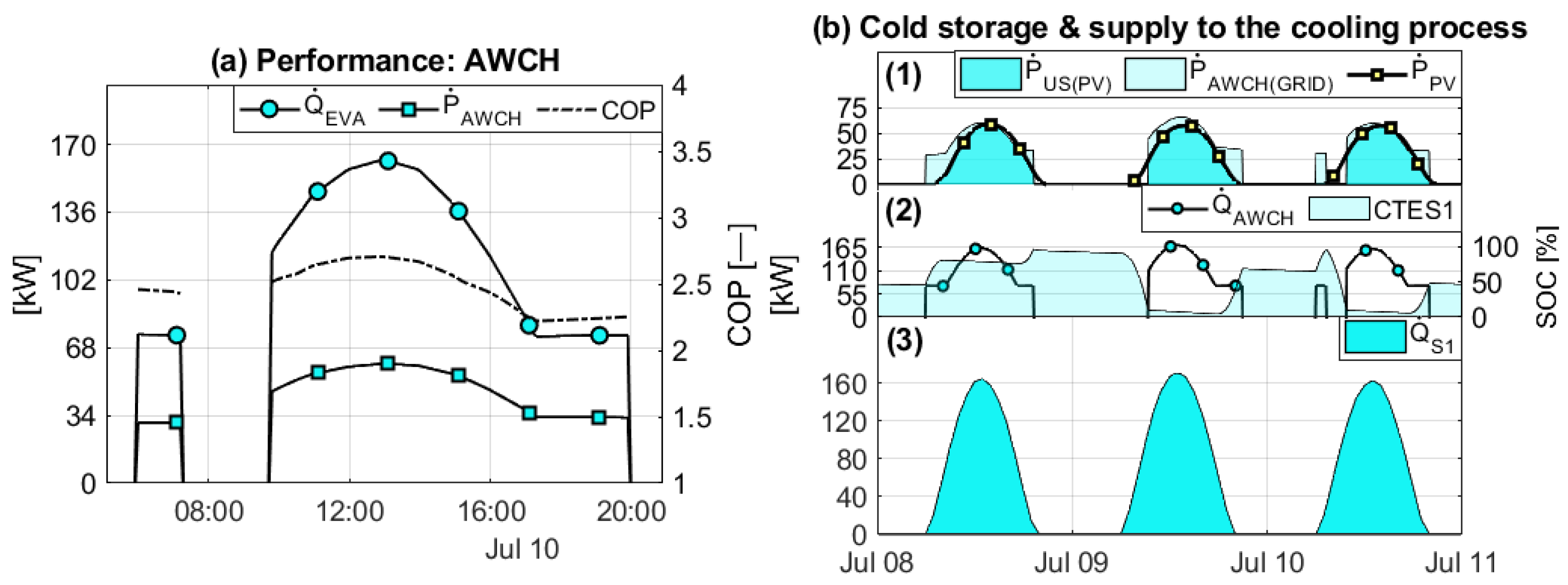
Figure 14a shows the behavior of the AWCH of the individual PV system, the AWCH consumption electricity (
),
, and the COP for the day July 10th.
Figure 14(b1) shows the total power production of the PV field (
), the useful power consumed by the system (
), and the power provided by the electric grid (
). It can be observed that almost all of the
is consumed by the PV-AWCH system. However, due to the charge control conditions and minimum
of operation, there is a
that tends to exceed the
during the first hours of the morning and the last hours of the day.
Figure 14(b2,b3) show the SOC of the system and the coverage of the cooling demand of the system with the main chiller (
), respectively. The SOC of the CTES is close to a total discharge on July 9 and 10, due to the system prioritizing the CTES charge during radiation hours.
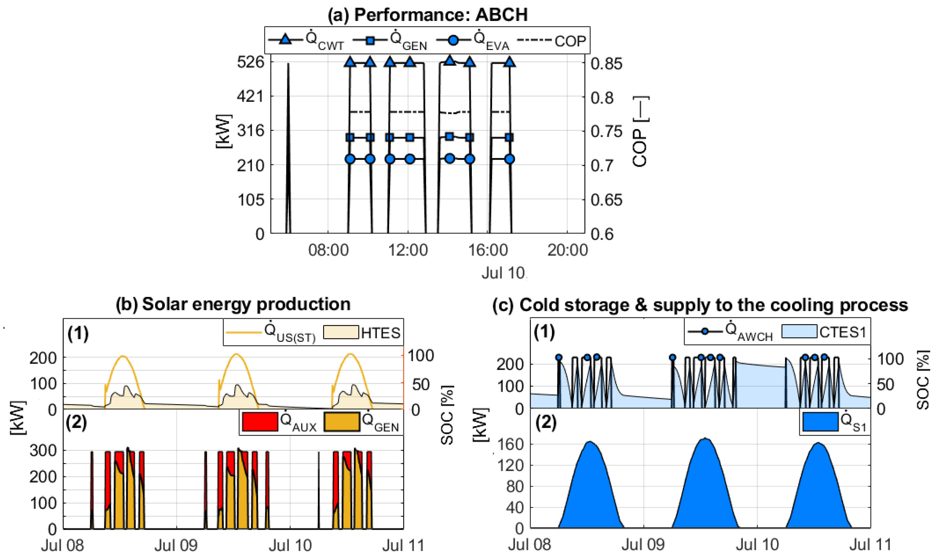
Figure 15 shows the behavior of the individual ST-ABCH system. It is important to note that
Figure 15a shows the performance of the ABCH with
C, due to these results being recorded during the period of maximum system load. In addition, the ABCH increases its capacity by approximately 20% relative to its nominal capacity due to maintaining a
C. However, the operating conditions make it necessary to maintain a heat demand of close to 300 kW, which means a heat demand from the generator that is greater than 40 % with reference to the heating demand.
Figure 15b shows that, despite having a solar field area of 380 m
, a contribution of
close to 75% of the total demand is required during the first and last hours of the day.
Figure 15c shows the SOC of the CTES in which the activation of the ABCH is appreciated once it reaches full discharge, maintaining coverage of
of the cooling demand.
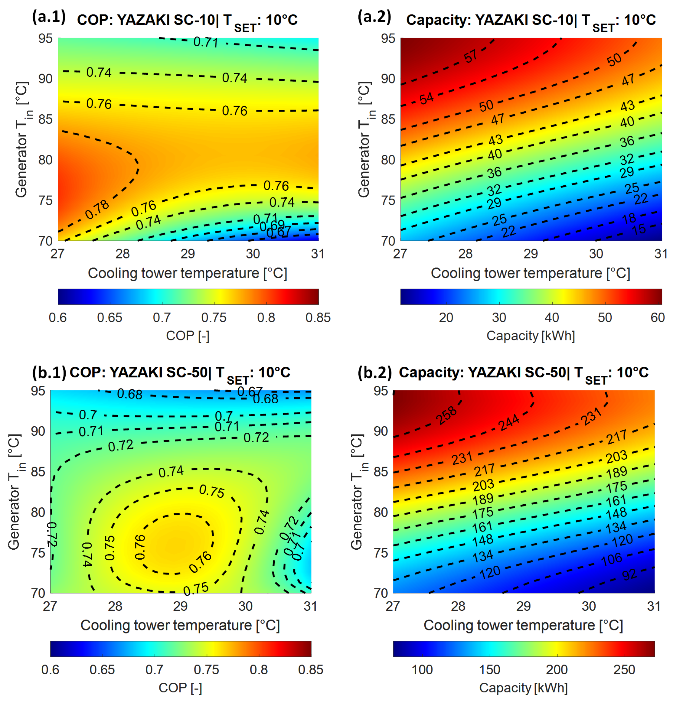
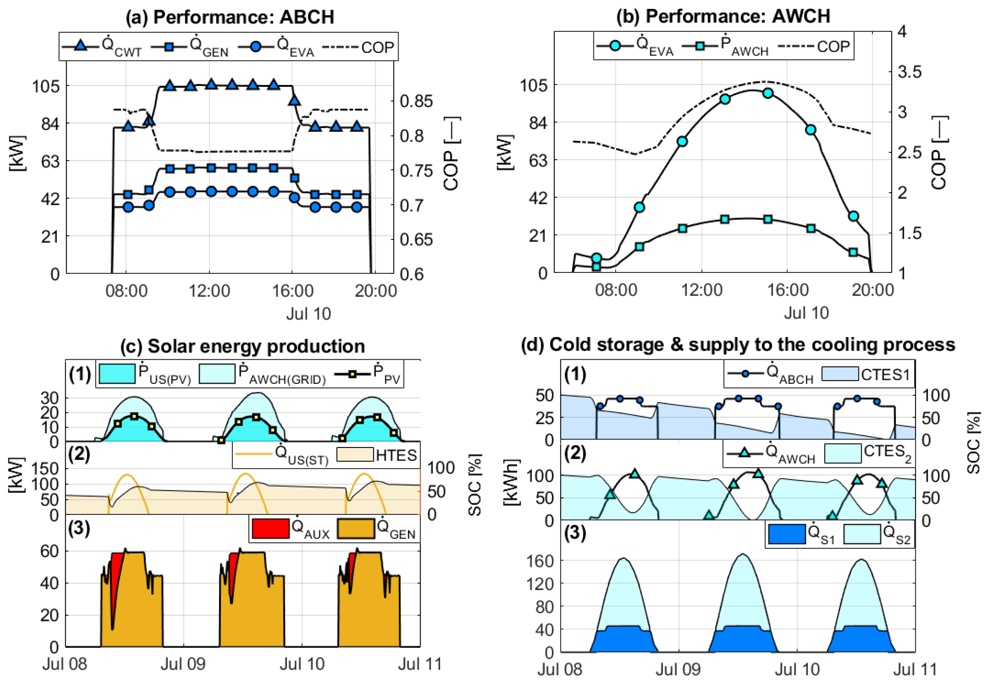
Figure 16a shows the performance of the hybrid solar cooling system with the AWCH as the main chiller, with a nominal capacity (
) of 94 kW that can increase by
with a
of 10
C.
Figure 16b shows the performance of the ABCH with a
of 35 kW; in the same way, the performance of the ABCH can increase by 20% with respect to the nominal capacity. In contrast to the ABCH, the COP of the AWCH tends to increase over three if the
is lower than 30
C.
Figure 16(c1) shows that the
is insufficient to cover the total power consumption of the system. On the other hand,
Figure 16(c2) shows the
and the SOC of the HTES that supply heat to
.
Figure 16(c3) shows that the
decreases, and about 90% of heat is supplied, with the solar thermal system.
Figure 16d presents the SOC of the CTES1 and CTES2 with respect to the performance of the ABCH and AWCH, respectively. In that sense,
covers approximately 30% of the total cooling demand.
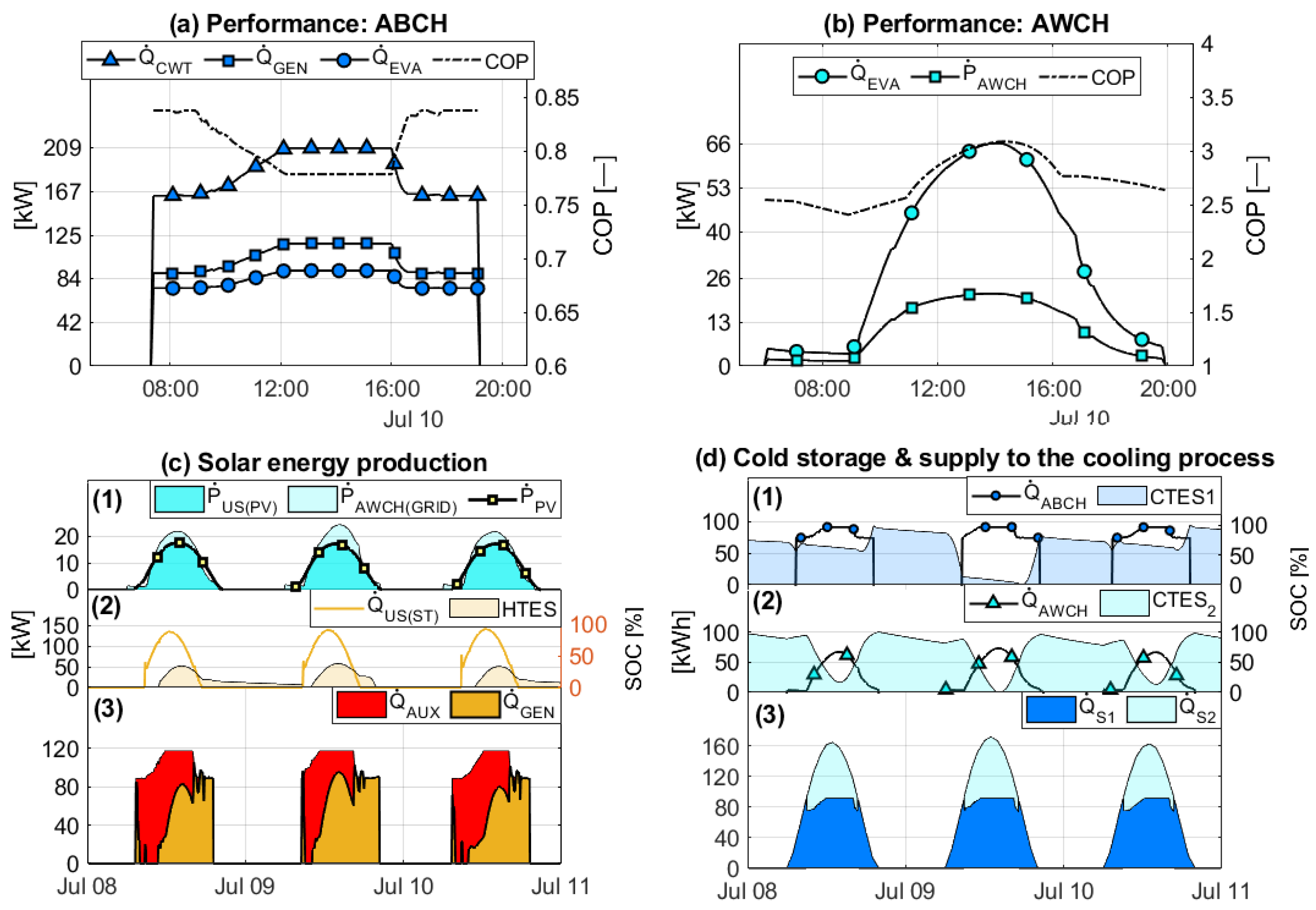
On the other hand,
Figure 17 presents the performance of the hybrid solar cooling system with an ABCH as the main chiller. The performance of the ABCH with a nominal capacity of 70 kW is shown in
Figure 17. The energy efficiency of the HYB2 system shows an increase of around 100% of the heat flow to satisfy the demand of the
. This allows
to cover approximately
of the cooling demand for the same time series. At the same time, 99% of the photovoltaic production is used to drive the AWCH, as shown in
Figure 17c.
Figure 18 shows the monthly behavior of the individual PV-AWCH (a) and ST-ABCH (b) systems with solar field areas of 269 m
and 244 m
respectively. The annual
(
) of the PV-AWCH system is 0.27, reaching a monthly
(
) of 0.65 and 0.67 during July and August. During the winter and autumn months, the PV system covers the electrical demand of the heating system pumps. However, this is less than
of the total energy consumption of the heating system. The advantage of the PV-AWCH lies in the high efficiency of the chiller, which is capable of reaching a COP higher than 2.5, which allows for attenuation of the low conversion efficiency of the PV modules. This means that the PV-AWCH system can achieve a system efficiency (
) of 0.85 and 0.77 in June and August, respectively.
On the other hand, the performance of the ST-ABCH system can achieve a of 0.72, due to having greater than 0.95 during the winter and autumn months. However, the maximum is 0.7 when the ABCH is on, decreasing to 0.49 during July. This is because the heat demand for the operation of the ABCH tends to be higher than the heating demand. In addition, it should be noted that the electrical consumption of the cooling system is around 5% of the total energy demand. Although the ST-ABCH system presents a high , the tends to be less than 0.3 during summer and less than 0.4 during winter, indicating an oversized solar field.
Figure 19 shows the hybrid system, which comprises a 244 m
ST collector field and a 34 m
PV field, totaling 278 m
. The HYB1 (a) system with the AWCH as the main equipment achieves a
of 0.86, whereas in July and August, it reaches
of 0.72 and 0.74, respectively. The
increases because the AWCH covers about 60% of the cooling demand, meaning a low heat demand requirement during the summer months. The energy reduction allows an
of 0.6 to be achieved during the months with cooling demand, increasing the
and
of the ST-ABCH system, which has a similar solar field area.
Meanwhile, the HYB2 (b) system increases heat demand because the ABCH covers 70% of the cooling demand. This results in a minimum of 0.6, due to the increased energy consumption of the boiler to supply the required heat to drive the ABCH. On the other hand, the efficiency increases to 0.5 and the consumption is reduced by around 40%, improving the indicators concerning the ST-ABCH reference system. However, the consumption of is increased by 99% with respect to the HYB1 configuration.
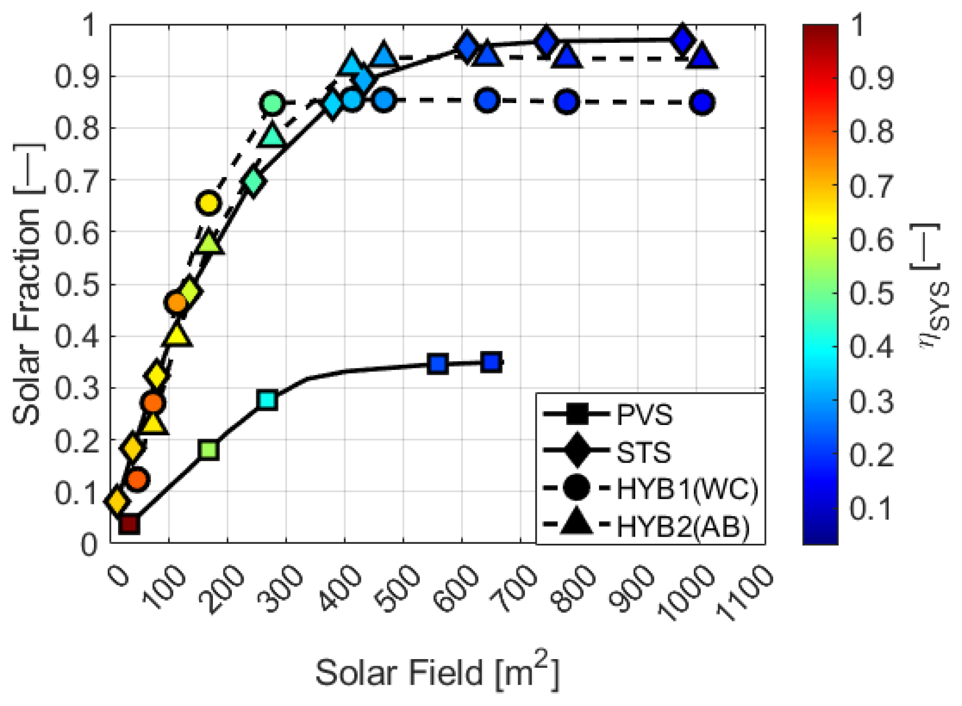
Regarding the annual results,
Figure 20 shows the behavior of the PV-AWCH, ST-ABCH, HYB1 and HYB2 systems for the
as a function of the solar field area, and the color bar shows the
. The ST-ABCH reaches the maximum
, with values close to 0.95, with a solar field larger than 700 m
. However, the
tends to be less than 0.2, due to the oversized area of the solar field with
. Meanwhile, the PV-AWCH reaches a maximum
of 0.35 because the system does not take advantage of the electrical production of the PV during winter, while the HYB1 reaches an
higher than the reference systems from 120 m
, reaching a maximum
of 0.85 and an
close to 0.4. On the other hand, the HYB2 shows improvements, with an area of 277 m
compared to the ST-ABCH but with a lower
than the HYB1.
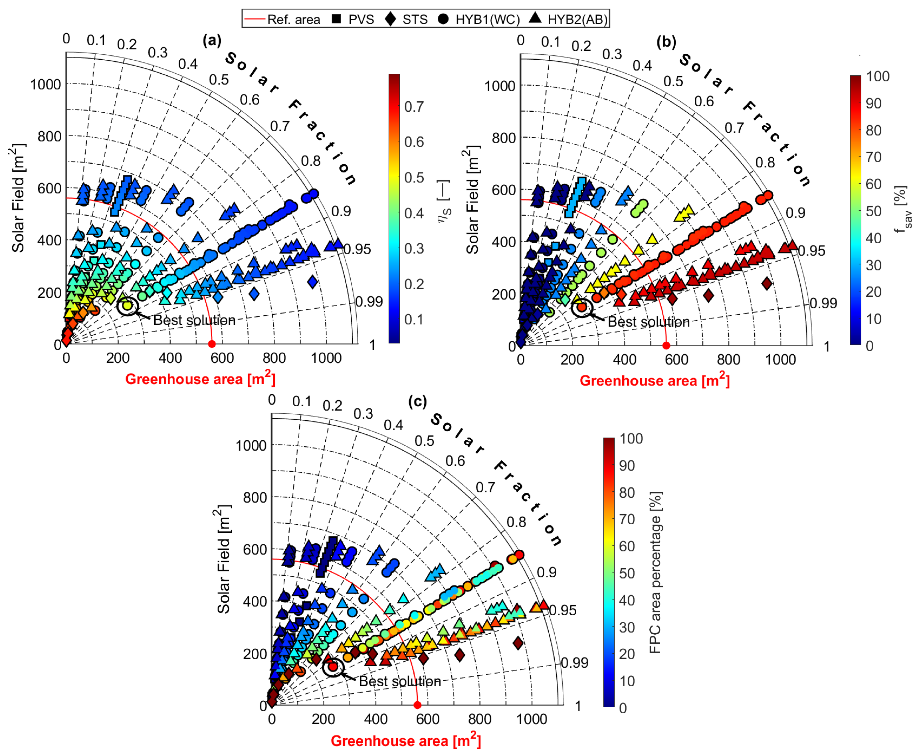
Figure 21 shows the behavior of the proposed schemes based on the area of the solar field, the area of the greenhouse, and the distribution of the
. The red line marks the maximum recommended installation area, while the scatter plot with the color bar shows: the efficiency of conversion of the system
(a), the fractional energy saved (
), and the percentage of occupation of the FPC. The PV-AWCH configuration achieves a maximum
of
, due to only covering the demand of the electric systems (pumps and AWCH). However, the best result of the PV-AWCH configuration, considering the reference area as a limit of the size of the solar field, achieves an
of
with an area of 336 m
and a
28%. On the other hand, the ST-ABCH configuration achieves an
of 0.97 with an area close to 1000 m
. Although the
is close to 99%, the area of the solar field exceeds the reference area by 87%. The most favorable result of the ST-ABCH system is with a field of 434 m
, capable of achieving
and
84%. On the other hand, the HYB1 configuration achieves a maximum of
and
84% with an area of 413 m
. However, the best result of the HYB1 is placed with an area of 278 m
, because it achieves
83% and
. The HYB1 achieves similar results to those of the ST-ABCH system with an area of 380 m
, but the HYB1 exceeds the
by 11%, while the HYB2 achieves
and
88% with an area of 414 m
, which, relative to the ST-ABCH reference system, represents an increase of 3% and 4% in the
and
, respectively. On the other hand, the best result of the HYB2 concerning the reference area is achieved with an area of 278 m
by reaching
and
62%, which, in relation to the ST-ABCH system with a similar area, represents an improvement of 12% of
and 40% of
.
In light of the results obtained, it can be determined that the hybrid configuration with the best energy results is the second, which has an AWCH as the main equipment, achieving an of 0.85 and a fossil energy saving of 83% with a composition of 12% of PV modules, which means that the solar field occupies 50% of the reference area available.

 ,
, 