Abstract
The article discusses the possibility of using glycerol as an additive to the engine fuel in order to reduce the tendency of combustion knock, and thus to increase the octane number of a given fuel. Experimental tests were carried out on the UIT-85 research engine with a variable compression ratio from eight to eleven to test the intensity of the knock. The completely renewable fuel—the blend of glycerol with butanol in the ratio of 25 and 75%, respectively—was tested. A comparative analysis of the knock intensity was conducted with gasoline 95 and N-butanol tested as reference fuels. The developed method for knock analysis using the proposed knock indicator was also presented. The experimental results proved the proposed blend of N-butanol and glycerol reduces the knock intensity by more than 50% in the spark-ignition engine at a compression ratio of 10, maintaining engine performance at a similar level as it was for a gasoline-fueled engine. The results confirmed the thesis on the reduction of knock intensity when adding glycerol to N-butanol.
1. Introduction
The topics raised in the article deal with fuel testing and knock analysis. Hence, the literature review was divided into two parts on these two topics. As the literature databases are rich in research works focused on the knock phenomenon and alcohol combustion in internal combustion (IC) engines, this introduction only presents exemplary references related to the key topics; however, they are not strictly correlated with the essence of the article, and hence, prove a gap in knowledge.
The tendency of IC engines to knock is one of the most important reasons limiting the thermal efficiency of engines. It prevents the achievement of an efficient combustion process, and limits the possibility of increasing the compression ratio. The knock results from the noise caused by the self-ignition of a certain part of the air-fuel mixture before the spreading flame front [1]. This phenomenon is inherent in the operation of IC engines and has been intensively researched for decades. There are several terms to describe this phenomenon as follows: combustion knock, engine knocking, or knocking combustion. High-frequency pressure oscillations occur in the combustion chamber during knocking combustion. The knocking combustion is harmful to the engine by causing damage mainly to the piston rings and piston crowns by melting and puncturing them. The results from knocking tests lead to a deeper understanding of combustion, and ultimately to improving engine construction, increasing durability, decreasing fuel consumption, and reducing toxic exhaust emissions and noise. The phenomenon consists of two characteristic phases. The first one is the flame propagation phase, which lasts from the ignition of the spark to the beginning of the pressure oscillation. In this phase, the temperature of the unburned mixture increases as a result of compression, caused by the exhaust gas and the piston motion, and heating because of the spreading flame. In the second phase, the pressure sharply increases to a maximum, and then oscillates with decreased amplitude. Self-ignition occurs as a result of reaching a sufficient level of pressure and temperature of the unburned mixture. The pressure wave, initiated by spontaneous combustion, propagates inside the chamber, reflects off its walls and causes pressure oscillations. The knocking combustion can be reduced by changing cylinder design and engine operating parameters as follows: spark timing, engine load and speed, air-to-fuel ratio, and exhaust gas recirculation. Another strategy is to modify a fuel so that it will be more resistant to generating knock, e.g., by adding some ingredients or blending with another liquid. In this paper, n-butanol blended glycerol is proposed as the engine fuel which is characterized by low knock willingness.
The knock has several faces. In modern small-capacity gasoline engines, the highest possible power needs to be performed from a small swept volume, and there is a risk of the so-called super-knock [2]. The super-knock can destroy the engine very quickly. Since super-knock occurs before ignition of the mixture, it is very violent, uncontrolled, and technically impossible to prevent by using appropriate sensors or ignition control. The knock resistance of fuels in SI engines is determined by the research octane number (RON) [3] and the motor octane number (MON). A higher octane number means greater resistance to fuel self-ignition. The paper [4] presents a broad and in-depth review of the knowledge about the processes occurring during knocking in spark-ignition engines, emphasizing recent advances in the field of their prevention in highly supercharged SI engines. It was found that knock or knocking can occur in modern combustion engines under conditions of high energy density, and that thermodynamic conditions and shock waves affect the initiation phases of the combustion and detonation wave. According to the authors [4], the most frequently observed was the mode of detonation initiated by the reflection of the shock wave, and this reflection is the main reason for self-ignition at the wall. The strategies for controlling the knock and individual combustion phases were also summarized, as well as the perspective directions of the research on knock combustion. Numerous works describe various techniques of knock detection [2,5,6,7,8,9,10] and methods of engine control to prevent knocking [3,7,11,12,13]. In order to better understand the knocking phenomenon, many studies were conducted on the basis of various diagnostics with the visualization of pressure waves and self-ignition [13,14,15,16,17]. The research on the knocking phenomenon is also carried out using numerical simulation methods based on various models of the combustion process, leading to the formation of knocking [1,18,19,20,21]. The negative effects of knocking combustion on engines are the motivation to research the possibilities to increase the octane number of fuels, most often by modifying the composition of fuels or introducing appropriate additives [22,23].
The content of the article deals with butanol and glycerol. Butanol is recognized as an alternative clean fuel for SI engines. Wei et al. [24] investigated the knocking combustion of gasoline blends with bio-butanol in an SI engine with direct injection. He found that pure bio-butanol has a better knock resistance, which was enhanced by increasing the ignition advance angle. The probability and cumulative distributions were used to assess the variability of knocking intensity of each fuel. The fuel, containing 20% bio-butanol (Bu20) compared to gasoline, had a slightly lower anti-knock resistance. In a study performed by Yang et al. [25] on the SI engine fueled by butanol-gasoline mixtures, it was found that the engine power was not reduced when butanol concentrations were below 20% by vol. Feng et al. [26] investigated the combustion efficiency in a diesel engine powered by bio-butanol and with gasoline injected into the intake manifold. It was found that at the optimal ignition angle, the indicated mean effective pressure (IMEP) increased, and with the increase of the bio-butanol mass fraction, the resistance to knock increased. Huang et al. [27] investigated the possibility of using a mixture of butanol and gasoline in a scooter SI engine with a capacity of 125 cm3. The fuels with the volumetric content of butanol from 10% to 100% were used. Research has shown that pure butanol increased engine performance at 4000 and 6000 rpm. Thomas et al. [28] investigated the influence of the compression ratio on the performance and emissions of an SI engine powered by a mixture of gasoline and bio-butanol at various loads. Measurements were performed at three different compression ratios (CR): 7:1, 8.5:1, and 10:1. The fuels used in this study were pure gasoline and a 20% N-butanol blend with gasoline. The results showed that with an increase in the compression ratio at all loads, the engine efficiency increased. Moreover, it has been found that the efficiency of the SI engine at partial load can be improved by using a variable compression ratio, especially when using fuels with better anti-knock properties. Niass et al. [29] found that the RON, the MON, and the heat of vaporization significantly increased for the gasoline-butanol mixture. Therefore, with advanced ignition, the efficiency increased at high and full loads, and thus, more favorable combustion conditions could be obtained. The increase in knock resistance assists with the reduction of CO emissions when the compression ratio was enhanced, or engine downsizing was performed. At medium loads, the identical or slightly better operating and emission parameters were defined. Galloni et al. [30] analyzed the performance of a downsized SI engines powered by gasoline and bio-butanol blends (20% and 40% bio-butanol blend by weight with gasoline). It was found that with the increase in alcohol content, the thermal efficiency decreased slightly (by approx. 4%) and that butanol increased the burning rate of poor mixtures. It has also been found that the ignition timing does not need to be adjusted when switching from pure gasoline to bio-butanol–gasoline blends. Scala et al. [31] analyzed the performance of a turbo-charged SI engine, powered by various butanol–gasoline mixtures, by numerical analysis. It was found that the optimal ignition timing for operating with an alcohol–gasoline mixture must be delayed (up to 13%) compared to pure gasoline. Irimescu et al. [32] investigated the use of N-butanol in an SI engine with direct injection, operating at low load and wide-open throttle (WOT). The correlation of the obtained thermodynamic data with flame images provided information on the evolution of chemical compounds (OH radical, soot precursors and carbon structures) during combustion. It was found that at low load, the alcohol performed slightly better than gasoline. However, at WOT, an opposite trend was observed. In the case of low coolant temperature, there was a liquid fuel film on the piston crown, which resulted in a slower flame spread. Merola et al. [33] conducted successful experimental tests on the SI optical engine with a 20% butanol-gasoline fuel injected into the channel mounted in the head of a commercial turbocharged SI engine. Deng et al. [34] investigated the effects of ignition timing, ratio of bio-butanol–gasoline mixture, engine load, and air-fuel ratio in a high-speed SI engine. It has been found that bio-butanol can provide a higher knock resistance, allowing for a more advanced ignition angle, leading to more efficient combustion. Czerwiński et al. [35] studied the different proportions of butanol in gasoline on a two-cylinder SI engine. They found that N-butanol blends with gasoline can reduce CO, HC, and NOx emissions in the raw exhaust gas, and have very little effect on the catalytic conversion factors of the three-way catalyst.
With regards glycerol, this is colloquially called glycerin and its chemical formula is: C3H8O3. The molecular structure of glycerol is presented in Figure 1. The main properties of glycerol are provided in Table 1.
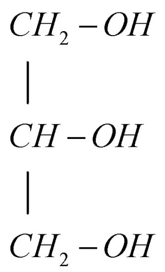
Figure 1.
Molecular structure of glycerol.

Table 1.
Properties of glycerol, N-butanol and gasoline 95.
Glycerol is a colorless, oily liquid with a sweet taste. It dissolves in water and alcohols, and does not dissolve in substances such as esters or chloroform. Originally, glycerol was obtained in the process of fat saponification. This reaction is well known because it produces glycerol and fatty acid salts, i.e., soap. Nowadays, glycerol is more and more often obtained from the biodiesel production process. Glycerol has many practical uses. It is a completely non-toxic substance. Glycerol is a substance with high hygroscopicity, i.e., the ability to absorb moisture, which is used, for example, in tanning to prevent the leather from drying out. Glycerol is also used as a sweetener in cough suppressant syrups. It is also used for the production of explosives (nitroglycerin). There are several works as regards to glycerol combustion in IC engines [36,37,38,39,40]. As found from a literary survey, glycerol has a high potential to be implemented as a fuel additive or a secondary fuel for IC engines. Nowadays, glycerol is mainly used in fuel blends at percentages up to 25% by volume. The problem of glycerol comes from its relatively high viscosity at ambient temperatures and high surface tension; these parameters have a negative effect on spraying, atomization, and primary and secondary break-ups while glycerol is injected into an engine cylinder.
In summary, the novelty and innovation presented in this article deal with the mixture of N-butanol of 75% and glycerol of 25% by volume which is considered an attractive fuel for the spark-ignition (SI) engine. As concluded from a literature review, there is a gap in the field regarding investigations of this mixture as a potential fuel for a reciprocating IC SI engine. Additionally, a new knock indicator was introduced and implemented into practice in this investigation.
2. Test Setup
The reciprocating internal combustion engine UIT-85 was used for the tests. It is a single-cylinder variable compression unit used to determine the octane number of fuel and is a clone of the Waukesha CFR1 engine. The technical data of the engine are given in Table 2.
Table 2.
Technical data of the engine UIT-85.
For research purposes, some significant changes were made to the engine. An open-water, forced cooling system with a water-air cooler and a thermostat-controlled electric fan was used. Electronically controlled ignition and injection system were used to manage the engine parameters, such as ignition angle, amount of fuel, and fuel injection angle. The electronically controlled encoder installed on the camshaft determines the instantaneous position of the crankshaft. A wideband lambda was used in the exhaust system, as well as a pressure sensor on the intake manifold and an air-flow meter and a piezoelectric pressure sensor. Temperature sensors were installed in the intake system, in the cooling system, and at the exhaust; ambient temperature data were transmitted to the data card. The engine as a research unit was equipped with a system working on gaseous and liquid fuels with the possibility of heating liquid fuel in the case of high viscosity. The complete test stand is presented in Figure 2.
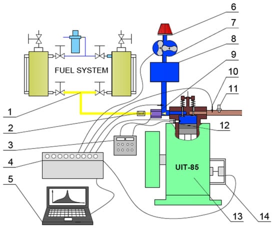
Figure 2.
The scheme of test bench. 1-fuel supply system; 2-fuel heater; 3-electronic injection and ignition control system; 4-data acquisition card; 5-computer for real-time analysis; 6-air filter; 7-rotor flow meter; 8-air reservoir; 9-fuel injector; 10-exhaust gas temperature sensor; 11-universal exhaust gas oxygen (UEGO) sensor; 12-spark plug equipped with a piezoelectric pressure sensor; 13-UIT-85 research engine; 14-encoder on the camshaft.
The test bench consisted of a fuel system (1), which includes two fuel tanks allowing for quick replacement or refilling of fuels during the tests. The injection pressure (up to 10 bar) was adjusted by compressed air. Highly viscous liquid fuels can be heated by an electric heater (2) and then fed into the fuel injector (10). An electronic system (3) was used to control the injector, which ensures the control of the start of injection and injection time, electric discharge time, and spark energy. The system used an encoder (14) installed on the camshaft and synchronized with the engine. A data acquisition card (4) collected temperature data of the engine cooling system, the engine intake air, and the exhaust gas. Additionally, the data acquisition card (4) recorded the impulses from the encoder (14) and from the pressure sensor built into the spark plug (12). The computer (5) with the SAWIR application was used to analyze the engine parameters. The air intake system contained the air filter (6), a rotor air flow meter (7), and a pressure pulsation compensator (8) with a capacity of 120 dm3. The exhaust gas temperature sensor (10) and a universal exhaust gas oxygen (UEGO) sensor (11) with a controller were installed in the exhaust system. The exhaust gas analyzer (15) enabled continuous analysis of the exhaust gases. The test engine (13) can operate with an adjustable speed and variable load. Instrumentation and the uncertainties used in tests are presented in Table 3.
Table 3.
Instrumentation of the measurement system.
2.1. Methodology
The investigation was taken on the basis of comparative analysis with 3 fuels as follows:
- N-Butanol+Glycerol at ratio of 3:1 respectively
- Gasoline 95
- N-Butanol.
Gasoline and N-butanol were used as reference fuels to show any differences and similarities to the main fuel, which was a mixture of N-butanol of 75% and glycerol of 25% by volume.
The comparative analysis conducted in this investigation is based on measurements of the following parameters:
- Indicated Mean Effective Pressure (IMEP) of the engine,
- Knock Intensity (KI),
- Knock-to-Power indicator.
All three parameters were calculated on the basis of in-cylinder pressure data sampled at a 100 kHz frequency.
As far as the IMEP does not need any detailed explanation, the knock intensity KI was calculated as the maximum amplitude of in-cylinder pressure pulsations during the combustion phase after filtering the raw in-cylinder pressure (Figure 3a) with the high-pass Butterworth filter of 4th order and a cut-off frequency of 3.5 kHz as depicted in Figure 3b. This approach for determining knock intensity is relatively simple and therefore commonly used in research. In other papers, this parameter is named MAPO (maximum amplitude of pressure oscillations).
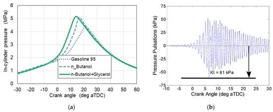
Figure 3.
(a) Exemplary in-cylinder pressure for the tested fuels; (b) in-cylinder combustion pressure pulsations for KI calculations.
For the comparative analysis a new indicator denoted Knock-to-Power was proposed from Equation (1):
where KIRel is a dimensionless, relative factor expressing ratio of knock intensity of the engine working on tested fuel (KITF) to knock intensity of the engine fueled by a referenced fuel (KIRef) at its optimal spark timing for this fuel as described by Equation (2).
where IMEPRel is a dimensionless, relative factor expressing a ratio of indicated mean effective pressure of the engine working on the tested fuel (IMEPTF) to IMEPRef of the engine fueled by the referenced fuel at its optimal spark timing for this fuel as presented with Equation (3).
This dimensionless indicator, defined as the ratio of relative parameters for knock intensity and engine load, is to be used to evaluate the possibility of using an unknown fuel in the engine with respect to obtaining the maximum power and minimum knock in reference to a known fuel at its known operating settings, e.g., spark timing. Additionally, it can provide the possibility of easier optimization of the engine operation on this unknown fuel. It was recognized that simply determining RON as an indicator of knock resistance for a given fuel will not be reliable, because it does not relate to engine performance, which is affected not only by fuel quality (i.e., RON), but also by its lower heating value (LHV), combustion rate, and maximum flame temperature. In some cases, intense knocking occurs beyond the range of the effective engine operation at max. IMEP or maximum brake torque (MBT). However, it is also the case that the knock occurs earlier and accompanies engine work, thus limiting the engine’s operating range and not allowing it to enter optimal operating conditions. This indicator proposed here can solve several problems and might point out research targets.
2.2. Test Matrix
The tests were conducted following parameters depicted in Table 4. Table includes parameters that were varying and fixed during the tests. The combustion was at a stoichiometric ratio at the maximum possible engine performance at WOT. Although engine load expressed by the IMEP was not constant, but assuming WOT conditions, the maximum possible IMEP was generated.
Table 4.
The tests parameters.
3. Results and Discussion
At the beginning, the results of IMEP vs. the ignition angle for the tested fuel and the two reference fuels (gasoline and N-butanol) are presented (Figure 4a,c,e). With the aid of these graphs, it is possible to determine the optimal ignition angle at which the engine achieves the highest IMEP at various compression ratios in the range of 8 to 11, which corresponds to the highest indicated efficiency assuming both a constant fuel dose and engine speed. One can observe that at the higher CR, the spark timing is closer to the TDC. This is a well-known correlation for the IC engine. At a higher CR there is a higher temperature at spark timing that consequently affects faster flame propagation, hence, higher combustion rate, and as a result, the maximum IMEP is generated closer to the TDC. As depicted in Figure 4a, the optimal spark timing for a gasoline-fueled engine was not achieved for the CR of 11. It was caused by the relatively high knock intensity over 200 kPa when the spark timing occurred earlier than −6 CA deg aTDC; therefore, the engine was not operated at this range. However, this partially conducted test was depicted in Figure 4a,b. Figure 4b,d,f shows knock intensity KI vs. spark timing for the tested fuels under the same various compression ratios. As observed, knock intensity KI increased with advancing the spark timing. As mentioned, the KI calculations were obtained from the same tests depicted in Figure 4a,c,e. Based on a number of research studies, it was assumed that a knock intensity KI above 60 kPa may be burdensome on the engine and may shorten its life. On the other hand, the knock above 100 kPa is so strong that engine operation in the conditions leading to this knock is unacceptable. As observed in Figure 4f, the mixture of butanol and glycerol (denoted as N-Butanol + Glycerol) is characterized by the lowest KI, which does not exceed 100 kPa except the test for CR = 11 at ST earlier than −14 CA deg aTDC. On this basis, it can be stated that glycerol is a substance that reduces the maximum flame temperature and thus slows down the combustion process. Hence, the lower flame temperature and lower combustion reaction rates should positively reduce the formation of local self-ignition centers.
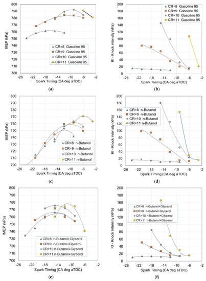
Figure 4.
IMEP and knock intensity vs. spark timing for the tested fuels at various compression ratios: (a) IMEP for Gasoline 95; (b) KI for Gasoline 95; (c) IMEP for N-Butanol; (d) KI for N-Butanol; (e) IMEP for N-Butanol + Glycerol; (f) KI for N-Butanol + Glycerol.
The test with a compression ratio of 10 was selected for further analysis because this one is commonly used in modern spark-ignition engines. There are several correlations of knock intensity with other combustion parameters. For example, typical combustion analysis deals with the heat release rate (HRR) (Figure 5a) and cumulative heat released from combustion recalculated to the normalized range from zero to one (Figure 5b). The representation of HRR and cumulative heat plots for comparison requires the same scale as the crank angle axis. These HRR and cumulative heat courses were calculated for the optimal spark timings, which were different for the tested fuels. Therefore, in order to make a comparison between the HRR plots, it was decided to present them by taking the spark timing as a reference point shown in Figure 5 as “Spark Timing”. Hence, the horizontal axis represents the relative crank angle and starts with “zero” from the beginning of combustion. As observed, there are no significant differences associated with the knock intensities and heat release rates for these tested fuels. The sharp peak on the butanol combustion course is caused by a so-called “rumble” effect known from gasoline combustion. One can conclude that this “rumble” effect might contribute to higher in-cylinder pressure pulsations during butanol combustion, as does knock intensity. Furthermore, as a result of higher HRR, the combustion progress is faster for N-butanol in comparison with other tested fuels, as depicted in Figure 5b.
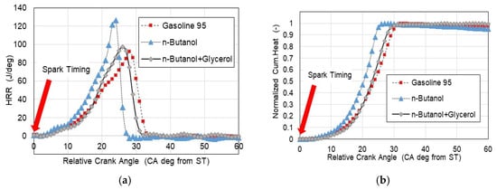
Figure 5.
(a) Heat release rate vs. relative crank angle; (b) normalized cumulative heat released vs. relative crank angle for the tested fuels.
Figure 6 presents both IMEP and KI for various spark timings at a compression ratio of 10 for these three tested fuels. The maximum IMEP was marked with a bar also showing the optimal spark timing associated with the IMEP maximum. Additionally, KI was inserted in these diagrams. As found, the KI for optimal spark timings for these fuels was in the range from 40 to 60 kPa. On the other hand, the IMEP maximum varied more significantly, changing from nearly 790 kPa for gasoline and decreasing to 775 kPa for N-Butanol + Glycerol. Thus, from this point of view, one can conclude that the engine, at its optimal spark timing, operated on gasoline works more efficiently because it generates higher IMEP at a similar knock intensity.
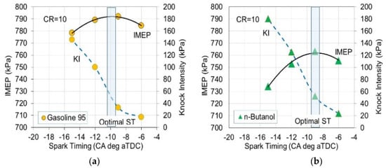
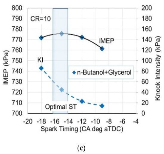
Figure 6.
IMEP and knock intensity KI vs. spark timing for the tested fuels at a compression ratio of 10: (a) for Gasoline 95; (b) for N-Butanol; (c) for N-Butanol + Glycerol.
As previously mentioned in the Methodology section, a specific knock indicator Knock-to-Power was proposed that took into account, apart from the knock intensity, the engine performance expressed by IMEP. For the analysis presented here, the Knock-to-Power indicator for the operation of the engine on gasoline 95 at a compression ratio of 10 and ST = −10 generated the highest IMEP. Therefore, this indicator should be used to assess the performance and intensity of the knock occurring for an engine operating on different fuels. This approach may come as a bit of a surprise when one notices that the absolute knock value is the most significant quantity in terms of engine life. However, the knock related to engine performance (IMEP in this case), as defined by the indicator Knock-to-Power, should provide additional information of a potential for higher power with a knock occurring at a safe level that is harmless for the engine. Thus, this indicator characterizes not only the fuel (just like the index called octane number), but it illustrates the specific engine-fuel system. As shown in Figure 7, Knock-to-Power, in some conditions, exceeds a value of three. This means the relative knock intensity KIRel is 3-times higher than the relative IMEPRel referring to absolute values for KIRef and IMEPRef for gasoline at an ST = −10 CA deg aTDC at CR = 10.
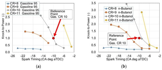
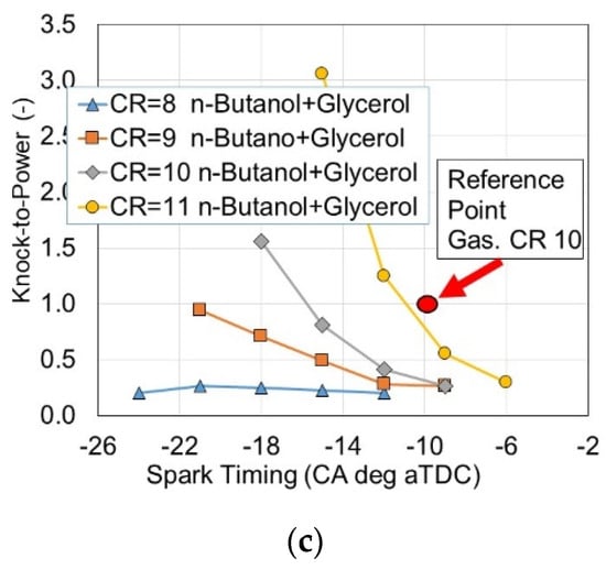
Figure 7.
Knock-to-Power indicator vs. spark timing for the tested fuels at various compression ratios: (a) for Gasoline 95; (b) for N-Butanol; (c) for N-Butanol + Glycerol.
As can be seen in Figure 8, the operation of the engine on N-butanol is the most unfavorable, because, with a knocking intensity similar to that of gasoline, the engine achieves a significantly lower IMEP value, and thus lower power and lower efficiency and, consequently, lower overall efficiency. The most effective work is for the engine fueled by a mixture of butanol and glycerol. The engine achieves satisfactory performance with the relatively low Knock-to-Power indicator, as shown in Figure 8 and presented in Table 5.
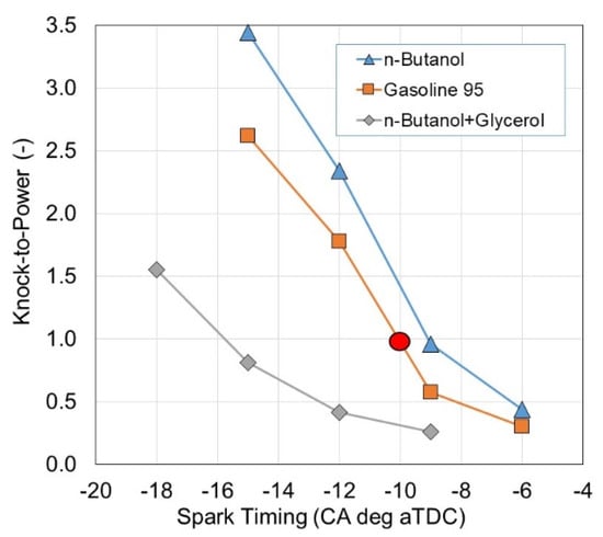
Figure 8.
Knock-to-Power vs. spark timing for the tested fuels at a compression ratio of 10.
Table 5.
The data for normalized Knock-to-Power.
Table 5 provides data for normalized Knock-to-Power, knock intensity KI, and IMEP at optimal spark timing at a compression ratio of 10, as it was earlier assumed for gasoline combustion tests. In Table 5 one can notice the absolute results for KI are comparable with each other for gasoline and N-butanol; however, the Knock-to-Power indicator is definitely lower, i.e., more favorable for gasoline. This indicator is even better for a mixture of glycerol and butanol. It can be concluded that the lower this indicator, the greater the possibility of obtaining better engine performance (power, IMEP). This is because KI increases more slowly than IMEP. This indicator is a value that can be used to characterize the drive unit: engine + fuel.
4. Conclusions
The following conclusions were drawn from the investigation focused on applying the proposed fuel consisting of butanol and glycerol:
- The novelty of the research work presented in this article deals with a new blend, which consist of glycerol and N-butanol, which are renewable liquids.
- Glycerol added to N-butanol at the percentage of 25% by volume decreases knock intensity in a spark-ignition engine.
- The mixture of 75% N-butanol and 25% glycerol can be combusted in the engine working at a compression ratio of 11. As compared to gasoline combustion tests, the knock is at the acceptable level of below 60 kPa at the optimal spark timing of −10 CA deg aTDC for a maximum of IMEP.
- The proposed mixture of butanol-glycerol at the volumetric percentage of 75–25, respectively can be treated as a fully renewable fuel for a spark-ignition engine working as a propulsion unit in a vehicle or a power generation set.
- Regarding the indicator Knock-to-Power, its significantly low value for the proposed mixture of 75% N-butanol and 25% glycerol, in comparison to gasoline tests at compression ratio of 10, provides the premises for the potential to work at higher compression ratios.
- The proposed Knock-to-Power indicator for knock evaluation is the innovative quantity developed for the purpose of linking knock and engine load in a dimensionless grading.
- The indicator Knock-to-Power is considered a valuable tool to assess the potential of heavy knock occurrence under engine load.
Author Contributions
Conceptualization, S.S.; methodology, S.S., M.G. and R.J.; software, M.G.; validation, S.S., M.G. and M.P.; formal analysis, S.S. and R.J.; investigation, M.G. and M.P.; data curation, M.G.; writing—original draft preparation, S.S.; writing—review and editing, S.S. All authors have read and agreed to the published version of the manuscript.
Funding
The research was supported by university funding for R&D.
Data Availability Statement
Data available on request.
Conflicts of Interest
The authors declare no conflict of interest.
Abbreviations
| aTDC | after top dead center |
| CA | crank angle |
| CI | compression ignition |
| CO | carbon monoxide |
| CR | compression ratio |
| HC | hydrocarbon |
| HRR | heat release rate |
| IC | internal combustion |
| IMEP | indicated mean effective pressure |
| KI | knock intensity |
| LHV | lower heating value |
| MON | motored octane number |
| NOx | nitric oxides |
| RON | research octane number |
| SI | spark-ignition |
| WOT | wide-open throttle |
References
- Heywood, J.B. Internal Combustion Engine Fundamentals, 2nd ed.; McGraw-Hill College: New York, NY, USA, 2018; ISBN 9781260116106. [Google Scholar]
- Kalghatgi, G.T.; Bradley, D. Pre-Ignition and ‘Super-Knock’ in Turbo-Charged Spark-Ignition Engines. Int. J. Engine Res. 2012, 13, 399–414. [Google Scholar] [CrossRef]
- Mehl, M.; Chen, J.Y.; Pitz, W.J.; Sarathy, S.M.; Westbrook, C.K. An Approach for Formulating Surrogates for Gasoline with Application toward a Reduced Surrogate Mechanism for CFD Engine Modeling. Energy Fuels 2011, 25, 5215–5223. [Google Scholar] [CrossRef]
- Wang, Z.; Liu, H.; Reitz, R.D. Knocking Combustion in Spark-Ignition Engines. Prog. Energy Combust. Sci. 2017, 61, 78–112. [Google Scholar] [CrossRef]
- Ettefagh, M.M.; Sadeghi, M.H.; Pirouzpanah, V.; Arjmandi Tash, H. Knock Detection in Spark Ignition Engines by Vibration Analysis of Cylinder Block: A Parametric Modeling Approach. Mech. Syst. Signal Process. 2008, 22, 1495–1514. [Google Scholar] [CrossRef]
- Molinaro, F.; Castanié, F. Signal Processing Pattern Classification Techniques to Improve Knock Detection in Spark Ignition Engines. Mech. Syst. Signal Process. 1995, 9, 51–62. [Google Scholar] [CrossRef]
- Jones, J.C.P.; Spelina, J.M.; Frey, J. Likelihood-Based Control of Engine Knock. IEEE Trans. Control Syst. Technol. 2013, 21, 2169–2180. [Google Scholar] [CrossRef]
- Novella, R.; Pla, B.; Bares, P.; Jiménez, I. Acoustic Characterization of Combustion Chambers in Reciprocating Engines: An Application for Low Knocking Cycles Recognition. Int. J. Engine Res. 2020, 23, 120–131. [Google Scholar] [CrossRef]
- Barbosa, R.; Galvagno, A.; Tajima, H.; Tomidokoro, T.; Yokomori, T. Deep Learning for Knock Occurrence Prediction in SI Engines. Energies 2022, 15, 9315. [Google Scholar] [CrossRef]
- Zou, F.K.; Zeng, H.; Wang, H.Y.; Wang, X.X.; Xu, Z.X. Implementation and Parameter Analysis of the Knock Phenomenon of a Marine Dual-Fuel Engine Based on a Two-Zone Combustion Model. Processes 2021, 9, 602. [Google Scholar] [CrossRef]
- Luo, W.; Chen, B.; Naber, J.; Glugla, C. Stochastic Knock Detection, Control, Software Integration, and Evaluation on a V6 Spark-Ignition Engine under Steady-State Operation. SAE Tech. Pap. 2014, 2014-01-1358. [Google Scholar] [CrossRef]
- Spelina, J.M.; Peyton Jones, J.C.; Frey, J. Stochastic Simulation and Analysis of a Classical Knock Controller. Int. J. Engine Res. 2015, 16, 461–473. [Google Scholar] [CrossRef]
- Zembi, J.; Battistoni, M.; Ranuzzi, F.; Cavina, N.; De Cesare, M. CFD Analysis of Port Water Injection in a GDI Engine under Incipient Knock Conditions. Energies 2019, 12, 3409. [Google Scholar] [CrossRef]
- Kołodziej, B.; Matyka, M. Odnawialne Źródła Energii. Rolnicze Surowce Energetyczne; PWRiL Sp. z o.o.: Poznań, Poland, 2012; ISBN 978-83-09-01139-2. [Google Scholar]
- Chłopek, M. Ciśnieniowa Aglomeracja Kompozytowych Paliw Stałych; Rozprawa d.; Akademia Górniczo-Hutnicza im. Stanisława Staszica: Kraków, Poland, 2015. [Google Scholar]
- Bembenek, M. Badania Wpływu Kształtu Powierzchni Roboczej Walców Na Efekty Pracy Prasy Walcowej; Praca dokt.; Akademia Górniczo-Hutnicza im. St.Staszica w Krakowie: Kraków, Poland, 2010. [Google Scholar]
- Ahn, B.J.; Chang, H.S.; Lee, S.M.; Choi, D.H.; Cho, S.T.; Han, G.S.; Yang, I. Effect of binders on the durability of wood pellets fabricated from Larix kaemferi C. and Liriodendron tulipifera L. sawdust. Renew. Energy 2014, 62, 18–23. [Google Scholar] [CrossRef]
- Sileghem, L.; Wallner, T.; Verhelst, S. A Quasi-Dimensional Model for SI Engines Fueled with Gasoline–Alcohol Blends: Knock Modeling. Fuel 2015, 140, 217–226. [Google Scholar] [CrossRef]
- Pipitone, E.; Beccari, S.; Genchi, G. A Refined Model for Knock Onset Prediction in Spark Ignition Engines Fueled With Mixtures of Gasoline and Propane. J. Eng. Gas Turbines Power-Trans. Asme 2015, 137, 111501. [Google Scholar] [CrossRef]
- Fontanesi, S.; D’Adamo, A.; Rutland, C.J. Large-Eddy Simulation Analysis of Spark Configuration Effect on Cycle-to-Cycle Variability of Combustion and Knock. Int. J. Engine Res. 2015, 16, 403–418. [Google Scholar] [CrossRef]
- Holly, W.E.; Lauer, T.; Schuemie, H.A.; Murakami, S. Prediction of the Knocking Combustion and NOx Formation for Fuel Gases with Different Methane Numbers. Int. J. Engine Res. 2016, 17, 35–43. [Google Scholar] [CrossRef]
- Rankovic, N.; Bourhis, G.; Loos, M.; Dauphin, R. Understanding Octane Number Evolution for Enabling Alternative Low RON Refinery Streams and Octane Boosters as Transportation Fuels. Fuel 2015, 150, 41–47. [Google Scholar] [CrossRef]
- Bradley, D. Combustion and the Design of Future Engine Fuels. Proc. Inst. Mech. Eng. Part C J. Mech. Eng. Sci. 2009, 223, 2751–2765. [Google Scholar] [CrossRef]
- Wei, H.; Feng, D.; Pan, M.; Pan, J.Y.; Rao, X.K.; Gao, D. Experimental Investigation on the Knocking Combustion Characteristics of N-Butanol Gasoline Blends in a DISI Engine. Appl. Energy 2016, 175, 346–355. [Google Scholar] [CrossRef]
- Yang, J.; Yang, X.; Liu, J.; Han, Z.; Zhong, Z. Dyno Test Investigations of Gasoline Engine Fueled with Butanol-Gasoline Blends. SAE Tech. Pap. 2009, 2009-01-1891. [Google Scholar] [CrossRef]
- Feng, D.; Wei, H.; Pan, M.; Zhou, L.; Hua, J. Combustion Performance of Dual-Injection Using n-Butanol Direct-Injection and Gasoline Port Fuel-Injection in a SI Engine. Energy 2018, 160, 573–581. [Google Scholar] [CrossRef]
- Huang, Q.J.; Chung, C.H.; Syu, Y.F.; Wu, Y.Y.; Li, C.K. Research on Applying Butanol-Gasoline Blend Fuel on Scooter Engine. SAE Tech. Pap. 2016, 2016-32-0056, 2688–3627. [Google Scholar] [CrossRef]
- Thomas, R.; Sreesankaran, M.; Jaidi, J.; Paul, D.M.; Manjunath, P. Experimental Evaluation of the Effect of Compression Ratio on Performance and Emission of SI Engine Fuelled with Gasoline and N-Butanol Blend at Different Loads. Perspect. Sci. 2016, 8, 743–746. [Google Scholar] [CrossRef]
- Niass, T.; Amer, A.A.; Xu, W.; Vogel, S.R.; Krebber-Hortmann, K.; Adomeit, P.; Brassat, A. Butanol Blending—A Promising Approach to Enhance the Thermodynamic Potential of Gasoline—Part 1. SAE Int. J. Fuels Lubr. 2012, 5, 265–273. [Google Scholar] [CrossRef]
- Galloni, E.; Fontana, G.; Staccone, S.; Scala, F. Performance Analyses of a Spark-Ignition Engine Firing with Gasoline–Butanol Blends at Partial Load Operation. Energy Convers. Manag. 2016, 110, 319–326. [Google Scholar] [CrossRef]
- Scala, F.; Galloni, E.; Fontana, G. Numerical Analysis of a Downsized Spark-Ignition Engine Fueled by Butanol/Gasoline Blends at Part-Load Operation. Appl. Therm. Eng. 2016, 102, 383–390. [Google Scholar] [CrossRef]
- Irimescu, A.; Merola, S.S.; Tornatore, C.; Valentino, G. Effect of Coolant Temperature on Air–Fuel Mixture Formation and Combustion in an Optical Direct Injection Spark Ignition Engine Fueled with Gasoline and Butanol. J. Energy Inst. 2017, 90, 452–465. [Google Scholar] [CrossRef]
- Merola, S.S.; Valentino, G.; Tornatore, C.; Marchitto, L. In-Cylinder Spectroscopic Measurements of Knocking Combustion in a SI Engine Fuelled with Butanol–Gasoline Blend. Energy 2013, 62, 150–161. [Google Scholar] [CrossRef]
- Deng, B.; Fu, J.; Zhang, D.; Yang, J.; Feng, R.; Liu, J.; Li, K.; Liu, X. The Heat Release Analysis of Bio-Butanol/Gasoline Blends on a High Speed SI (Spark Ignition) Engine. Energy 2013, 60, 230–241. [Google Scholar] [CrossRef]
- Czerwinski, J.; Güdel, M.; Engelmann, D.; Pechout, M. Influences of Butanol Blends on Combustion and Emissions of a Small SI Engine. SAE Tech. Pap. 2018, 2018-32-0058. [Google Scholar] [CrossRef]
- Beatrice, C.; Di Blasio, G.; Guido, C.; Cannilla, C.; Bonura, G.; Frusteri, F. Mixture of Glycerol Ethers as Diesel Bio-Derivable Oxy-Fuel: Impact on Combustion and Emissions of an Automotive Engine Combustion System. Appl. Energy 2014, 132, 236–247. [Google Scholar] [CrossRef]
- Gruca, M.; Pyrc, M.; Szwaja, M.; Szwaja, S. Effective Combustion of Glycerol in a Compression Ignition Engine Equipped with Double Direct Fuel Injection. Energies 2020, 13, 6349. [Google Scholar] [CrossRef]
- Presciutti, A.; Asdrubali, F.; Baldinelli, G.; Rotili, A.; Malavasi, M.; Di Salvia, G. Energy and Exergy Analysis of Glycerol Combustion in an Innovative Flameless Power Plant. J. Clean. Prod. 2018, 172, 3817–3824. [Google Scholar] [CrossRef]
- Szwaja, S.; Gruca, M.; Pyrc, M. Investigation on Ethanol-Glycerol Blend Combustion in the Internal Combustion Sparkignited Engine. Engine Performance and Exhaust Emissions. Fuel Process. Technol. 2022, 226, 107085. [Google Scholar] [CrossRef]
- Szwaja, S.; Gruca, M.; Pyrc, M.; Juknelevičius, R. Performance and Exhaust Emissions of a Spark Ignition Internal Combustion Engine Fed with Butanol–Glycerol Blend. Energies 2021, 14, 6473. [Google Scholar] [CrossRef]


Disclaimer/Publisher’s Note: The statements, opinions and data contained in all publications are solely those of the individual author(s) and contributor(s) and not of MDPI and/or the editor(s). MDPI and/or the editor(s) disclaim responsibility for any injury to people or property resulting from any ideas, methods, instructions or products referred to in the content. |
© 2023 by the authors. Licensee MDPI, Basel, Switzerland. This article is an open access article distributed under the terms and conditions of the Creative Commons Attribution (CC BY) license (https://creativecommons.org/licenses/by/4.0/).