1. Introduction
The future power grid is anticipated to incorporate a new generation of nuclear power plants that possess inherent safety features, environmentally sustainable operations, and cost-effective production of electricity, processing heat, and hydrogen. Recently, there has been a notable surge in the interest surrounding the development of nuclear reactors utilizing liquid fuels.
Several concept designs within the realm of GenIV reactors draw upon various forms of molten salt reactors (MSR) technology [
1,
2]. This utilization offers notable advantages, such as circumventing issues related to fuel poisoning and damage typically encountered in solid-state fuel systems during power plant operations.
Incorporating a fast neutron spectrum offers several advantageous outcomes, including the elimination of long-lived waste, improved safety characteristics, and enhanced utilization of nuclear fuel resources. The presence of strongly negative temperature coefficients, primarily driven by fuel thermal expansion, enables the reactor to self-regulate in response to external power demands [
3]. This capability allows for an appropriate reduction (or increase) in energy production to align with sudden surges (or declines) in power generated from renewable energy sources [
4].
The dual fluid reactor (DFR) [
5,
6,
7] possesses distinct advantages over traditional molten salt reactors (MSRs). Unlike a conventional MSR, where the molten salt serves as both the fuel and coolant, the DFR enables independent adjustment of the flow velocities for the fuel and coolant. This capability provides notable enhancements in terms of reactor economics and safety features to be added to its high energy returned over investment EROI [
8]. In addition, the utilization of DFR technology enables the implementation of online recycling and the establishment of a closed fuel cycle through the integration of a pyrochemical processing unit (PPU) [
9]. Moreover, DFR operating at temperatures exceeding 1200 K presents the opportunity for hydrogen production as an additional benefit to the electric power generation [
10].
On the other hand, the use of a liquid fuel also leads to additional challenges in reactor design resulting from thermal hydraulics (i.e., modeling of heat transfer and flow characteristics [
11]) and neutronics of circulating liquid fuel resulting in moving precursors [
3]. These analyses require taking different operational scenarios into consideration, for example starting up, shutting down, and accidents scenarios [
12]. Thus, a coupling of both effects in transient calculations of reactors are necessary [
13], and a precise simulation of the fuel flow plays a crucial role. Additionally, for DFR construction as a new concept, experiments and modeling validation are essential for both the design and licensing procedures as recommended by the IAEA [
14].
In a small modular DFR operating at an average temperature of 1000 °C, the heat exchange between the fuel and coolant transpires within the reactor core. The reactor core comprises numerous SiC ceramic pipes with small diameters, through which liquid uranium eutectics (U + Cr) flow. These pipes are enveloped by liquid lead, maintained at a lower temperature, thereby facilitating the heat transfer process [
15,
16].
This kind of design leads to complex thermal and hydraulic phenomena that determine the safety of the reactor both in normal operation and transition scenarios. Utilizing liquid metals results in very low Prandtl numbers of the flow. Thus, they should be tested experimentally and described numerically using validated computer codes. The first step in this way would be the construction of a non-critical mini demonstrator possessing all the main features of the real reactor. The uniqueness of this design lies in the exceptionally high operating temperature and the ability to study heat transfer between two separated liquids.
In this article, we present a comprehensive framework based on the principles of the dual fluid reactor, which incorporates distinct fuel and coolant loops. Our study focuses on investigating heat transfer phenomena between these loops at varying temperatures and flow velocities. Utilizing computational fluid dynamics, we aim to identify critical design aspects and determine temperature and velocity distributions within the flows. These findings are crucial as they will inform the ongoing design phase of the DFR, including safety analyses. Moreover, the results will be compared against experimental measurements from an upcoming experimental facility, enabling validation of the model employed in this study and exploration of potential refinements to enhance the accuracy of modeling the DFR, taking into account its geometric and operational parameters.
This study focuses on the CFD analysis of the MD core with the given DFR pipes dimensions and main thermal hydraulic parameters. The detailed mechanical workshop and design drawings for elements, connections, measuring devices, and components of the MD loops are beyond this study and shall be introduced in future work. The CFD modeling of the low Prandtl number fluids might require different models and techniques as the current models were not designed for this type of fluid with a smaller thermal boundary layer compared to the velocity boundary layer. This is because liquid metals typically have higher thermal conductivity and lower viscosity, which allows for efficient heat transfer and reduced resistance to fluid motion. Different attempts for establishing such a model are still developing [
17]. Two widely employed turbulence models in the field are the various versions of the k-ω SST model and the k-ε model. These models are commonly utilized to simulate flows of this nature, particularly in the context of the dual fluid reactor (DFR). Some other more complicated models adopted an additional transport equation, but these models are more suited to flow cases where a high Richardson number (Ri) is found; thus, the buoyancy forces and natural convection have a large role in the flow behavior [
18]. Notably, both models have demonstrated comparable results when applied to the DFR case [
16].
In this preliminary analysis study, the k-ω SST model was selected for two primary reasons. Firstly, this model has exhibited the highest possible accuracy comparable to the widely used k-ε model, thereby ensuring reliable results. Secondly, the k-ω SST model holds potential for future enhancements, warranting a comparison between the outcomes of the two modeling approaches. The standard form of the k-ω SST model incorporates a constant turbulent Prandtl number (Pr
t), typically set below unity (e.g., 0.85). In forthcoming research, investigating the utilization of a variable Prandtl number governed by an appropriate correlation is of interest. The present paper will serve as a valuable reference for facilitating this comparison and its potential implications [
19]. The enhancement of the heat transfer is crucial to the safety of the facility; this includes DFR and MD. This enhancement basically takes place in nuclear facilities using optimization of heat exchangers. In different applications, this type of optimization may be modeled using different techniques as genetic algorithm [
20]. In the case of carbon nanotubes, other methods were developed for this reason [
21].
Various numerical schemes have been developed to tackle the challenges associated with solving problems involving low Prandtl number fluids. Recent advancements have introduced new schemes that exhibit faster convergence rates and reduced computation times during simulations. These innovative schemes offer promising solutions for effectively and efficiently handling low Prandtl number fluid simulations [
22,
23]. Given that the current study focuses on modeling rather than simulation, the computation time did not pose a significant challenge. Therefore, the default code method for numerical discretization was employed in this analysis.
2. Materials and Methods
2.1. Description of Test Case
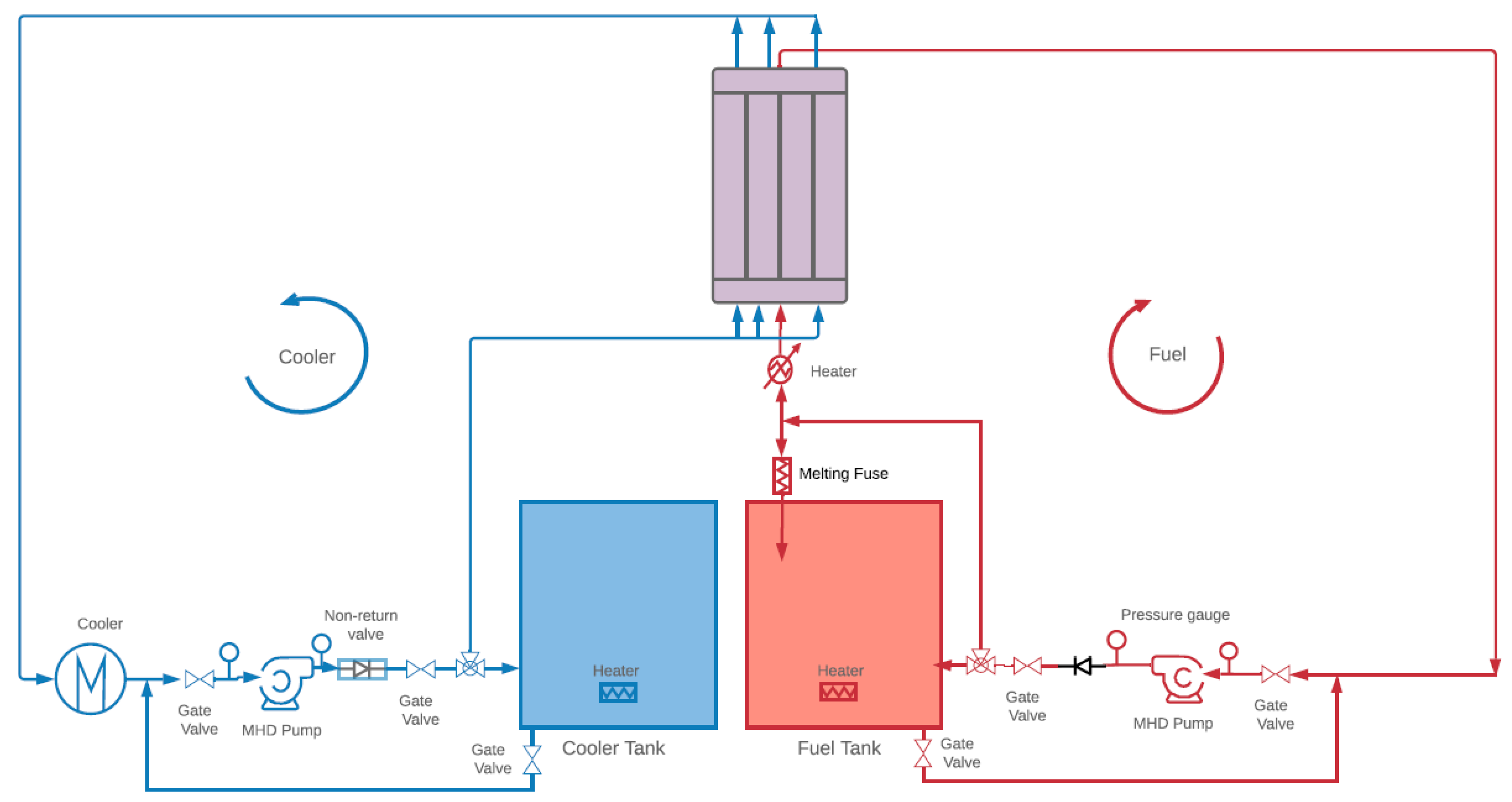
The mini demonstrator (MD) analyzed in this work consists of two pipe loops and a vessel (core) with several measuring and control devices, arranged in a specific order to acquire a required role
Figure 1. The MD has been developed as a simplified demonstrator to explore the thermal hydraulics of the dual fluid reactor (DFR) [
5]. Its primary purpose is to investigate the behavior of flows and the heat transfer process from the fuel to the coolant regions. The metallic variant of the DFR comprises two distinct loops: the fuel loop, which involves the uranium–chromium eutectic, and the coolant loop, which utilizes molten lead.
In present work, the MD is designed using two molten lead loops, without using the U–Cr eutectic, due to the ease of molten lead providence compared to the radioactive U–Cr in the research facility. The MD is equipped with various measuring and control devices. These components are meticulously arranged to fulfill specific functions within the system. Two magneto-hydraulic pumps (MHD) [
24,
25] are employed to facilitate the circulation of flows within the two loops. This type of pump is a commonly used type in lead and sodium cooled fast reactors [
26,
27] and molten salt reactors [
28,
29]. Each loop features a dedicated storage tank, which is equipped with internal heaters, as illustrated in the schematic diagram
Figure 1. Both tanks serve as sources of lead and can also function as storage units during shutdown or emergency situations.
Several valves, melting fuses, and a bypass passage are also implemented within the two loops to cope with different operation scenarios, for instance, in the event of fuel overheating, a melting fuse mechanism is incorporated. These fuses ensure that, if overheated, the entire quantity of fuel within the core is allowed to exit and descend into the storage tank under the influence of gravity. While the MD offers a diverse range of research possibilities, such as magneto-hydraulic pumps, corrosion, and material studies, the current research work is specifically dedicated to conducting preliminary thermal hydraulic analysis solely on the MD core. The investigation deliberately omits the study of other components within the cycle to maintain a focused approach.
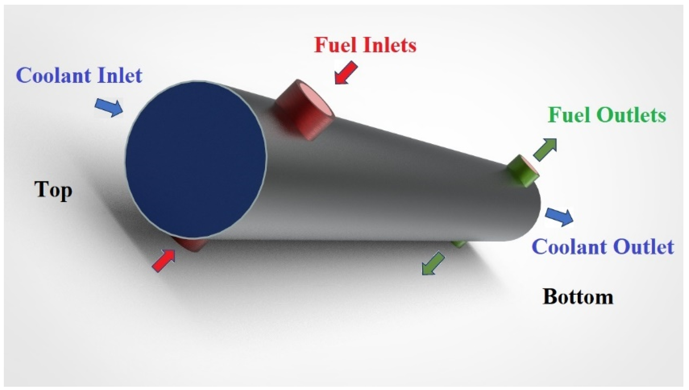
The two loops in the MD are separated without mixing at any point in the two cycles, similarly, in the actual DFR. The MD configuration includes two fuel inlets, two fuel outlets, one coolant inlet, and one coolant outlet (
Figure 2).
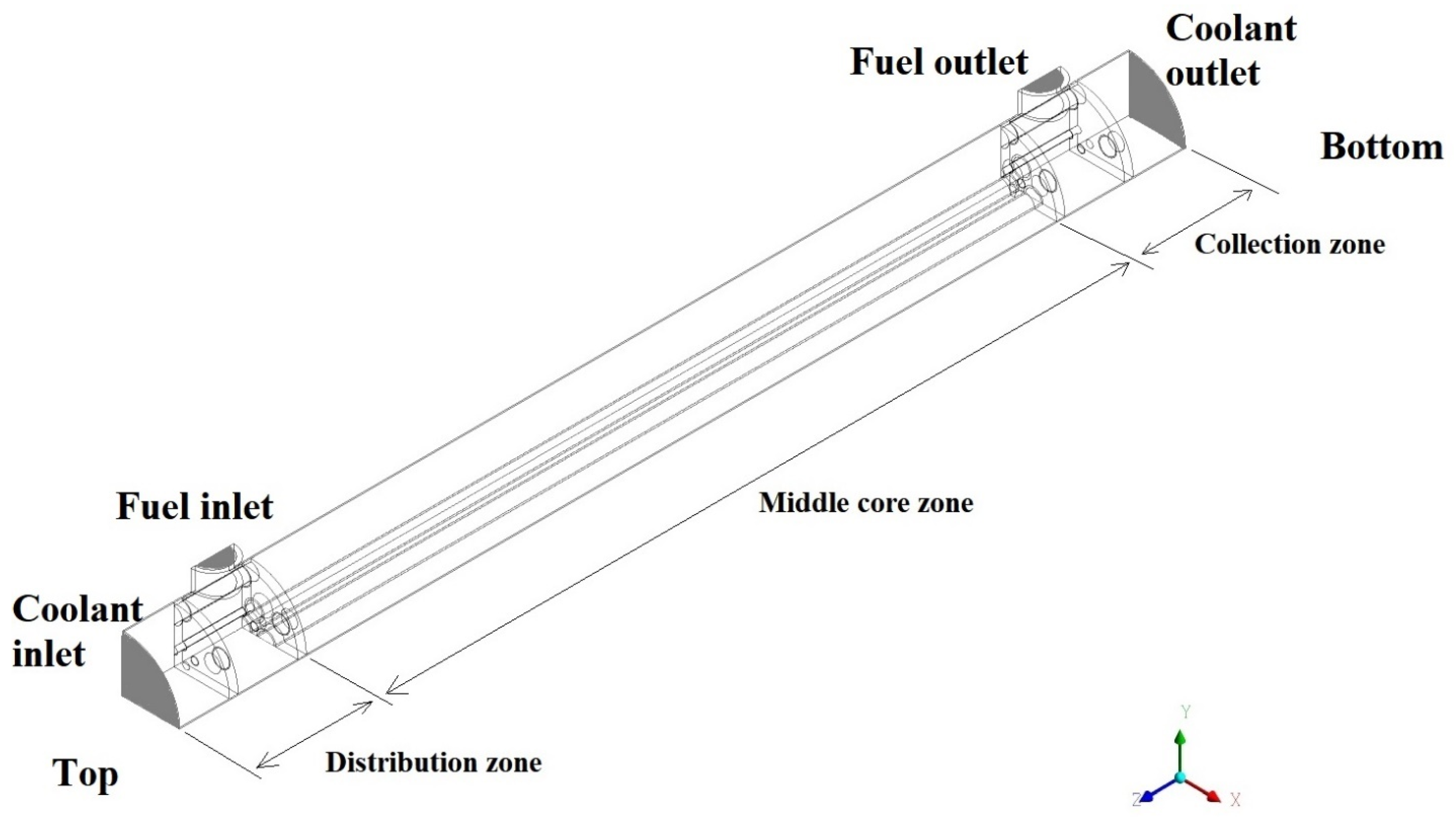
The MD core has three main zones:
Distribution zone: This is the zone between the fuel/coolant inlets and the middle core inlets. In this zone, the fuel and coolant enter the MD (from the top), where fuel surrounds the coolant pipes.
The middle core zone: In this zone, the fuel pipes are surrounded by coolant. The middle core zone is the largest section in the MD, and this is the zone where the major amount of heat transfer is expected to take place.
The collection zone: This zone lies between the middle core zone outlets and the outlets of the MD in an identical structure to that of distribution zone (bottom).
In
Figure 3, the three zones of the MD core are illustrated.
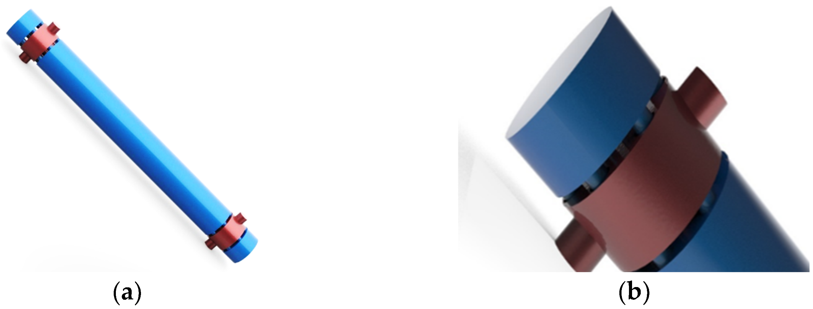
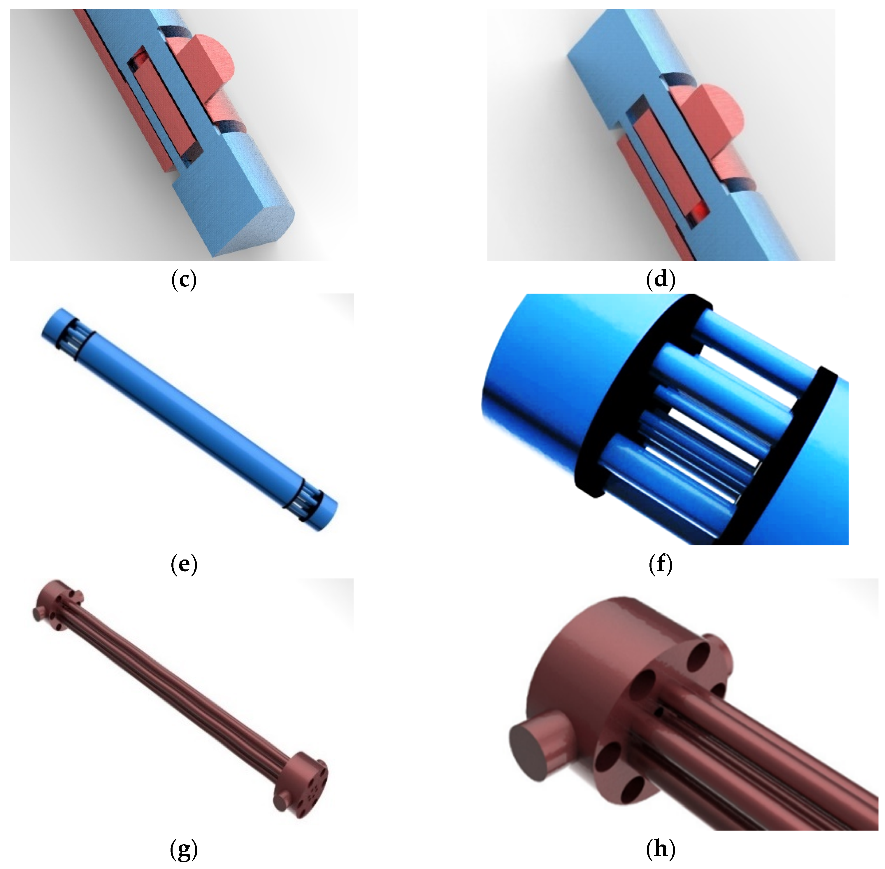
To optimize computational efficiency and reduce calculation time, the core of the MD was divided into four identical quarters with symmetrical walls in the relative directions (X and Y directions). This segmentation allows for a more manageable computational workload. Additionally, the same approach was used in structural figures to show the insights configuration of the MD core and pipes. For the same reason, the outer casing was hidden as well as the separation discs between zones (
Figure 4a,b).
The fuel is introduced into the MD through two inlets located at the top of the MD. Subsequently, it traverses a network of seven interconnected pipes (
Figure 4g,h). Within the middle core region, the fuel undergoes a progressive heat dissipation process as it exchanges heat with the coolant until reaching the exit. Subsequently, the fuel is transported to the collection zone, where it exits the MD through two outlets. From there, the fuel is returned to the heater for further processing (
Figure 1) after being pumped by the MHD pump. Similarly, the coolant flow is driven by another pump from the same type.
The coolant, as illustrated in
Figure 4e,f, enters the system through a single inlet and is distributed among six large diameter pipes and six small diameter pipes within the distribution zone. From there, the coolant proceeds towards the core, passing through these 12 pipes. It enters the core to occupy the space surrounding the fuel pipes. The primary heat absorption by the coolant takes place within the core region. Subsequently, the coolant exits through the same 12 pipes present in the distribution zone, ultimately leaving the mini-demonstrator collection zone via a single outlet.
2.2. Mathematical Background
The flow studied in this work is characterized by high Reynolds number. The Reynolds number based on average mean velocity and pipe diameters in different sections vary between 15,000 and 250,000 for the fuel and coolant, respectively. The k-ω turbulence model was employed in the present work to address the turbulent flow physics.
The standard k-ω model was originally proposed by Wilcox [
30] as an empirical model based on K and ω, where k is the turbulence kinetic energy and ω is specific dissipation rate, to describe the free stream outside the shear boundary layer. One of the remarkable improvements of this model was implementing the SST version of the k-ω model [
30].
For the standard k-ω model,
k and
ω can be obtained from the following equations, respectively:
where the turbulence kinetic energy generation is the generation of
ω,
and
are the diffusivity of
k and
ω, respectively.
Gb and
Gwb are buoyancy terms.
The SST model improvement is based on the Bradshaw’s assumption illustrating the proportionality between the main shear stress and the turbulent kinetic energy. The SST model is independent of the freestream values and shows better agreement with the experimental data.
The sheer stress can also be computed from the two-equation model from the form:
where
. Within the framework of the eddy viscosity model, redefining the eddy viscosity is then possible in the following form:
In adverse pressure gradient flows, the production of sheer stress is larger than the dissipation in the majority of the boundary layer; for this reason, the following expression is able to apply the shear stress equation for most of the adverse pressure gradient,
while for the rest of the boundary layer, the original expression is being used, which is
To keep the eddy viscosity model valid for the free shear layers, the modifications are only within the boundary layers; the following blending function is used:
where
is defined as below:
The
specifies its value based on the location as per its previously mentioned definition. For correcting the behavior of the flow over a flat plat boundary layer, the constants for SST model are expressed as below:
More information about the model can be found in [
31].
2.3. Computational Details
The model of the DFR core contains 7 fuel pipes (see
Figure 4g,h) and 12 coolant pipes (6 have larger diameter and 6 with a smaller one) (see
Figure 4e,f). Due to the geometric symmetry, only a quarter of the domain was considered in simulation. Detailed core parameters of the studied geometry can be found in
Table 1). The core parameters and dimensions were chosen to be within their corresponding ones in the DFR for best modeling experimental outcome benefits [
5,
32].
2.4. Boundary Conditions and Numerical Scheme
As mentioned, the k-ω model has been used in simulations of mini-demonstrator cases, taking into consideration the Y+ not exceeding 5 in the areas where significant heat transfer and velocity gradients are located (e.g., inside and outside surfaces of all fuel and coolant pipes). The energy equation was activated for the purpose of predicting heat transfer. The material properties of molten lead bismuth were manually added with proper correlations valid within the suitable temperature ranges as shown in
Table 2.
The inlet velocities of both fuel and coolant were set to be 0.1 m/s and 0.5 m/s, respectively, constant and perpendicular to the inlet’s surfaces. The atmospheric pressure was prescribed at outlets for fuel and coolant were set to be atmospheric as in the real reactor case. Detailed data of the boundary conditions can be found in
Table 3.
Second order upwind was used for discretization of convective terms in governing and transport equations. The normalized residuals for the governing and transport equations were driven to the level 10−5.
2.5. Meshing
Using sweep method wherever possible to mesh all sweepable bodies of the model, and different methods for the unsweepable bodies, the mesh was constructed carefully paying more attention to the boundary layers near the walls of the highest interest of investigation by adding the proper number of cells in the wall-normal direction (5–10 elements) with growth rate of 1.2 to fuel and coolant domains in the inner and outer sides of both fuel and coolant pipes).
Given the intricacy of the model, a small mesh size is essential to accurately capture the various phenomena and behaviors exhibited by the fluids during the simulation. This finer mesh resolution ensures that all relevant features and intricacies are reliably captured in the computational model.
A sensitivity analysis was conducted to evaluate the impact of different factors on the system. The analysis was conducted using one fuel pipe. Although the results of the analysis showed close values among the tested mesh sizes and number of elements, the intricate geometry and varying element sizes in different locations made the analysis challenging and difficult to implement a consistent mesh size change across the entire model. As a result, the sensitivity analysis was not conclusive and could not be universally applied. However, to be within the best possible y+ range required by the specific model, the finest mesh size 24 million elements was chosen for further calculations, relying on the statistical values of the mesh quality parameters that were found to be within the recommended values.
2.6. Validation of RANS Model
One of few facilities in the world used to test liquid lead systems to observe the behavior of the flow in various operational conditions is the TALL-3D facility in the Royal Institute of Technology, Stockholm, Sweden. An experiment has been performed in the facility that can be used here for the purpose of validation. The facility has two loops with a heat exchanger between them. Liquid lead–bismuth eutectic (LBE) was used as a coolant to the primary loop while the secondary loop has glycerol oil coolant. Further description can be found in [
33].
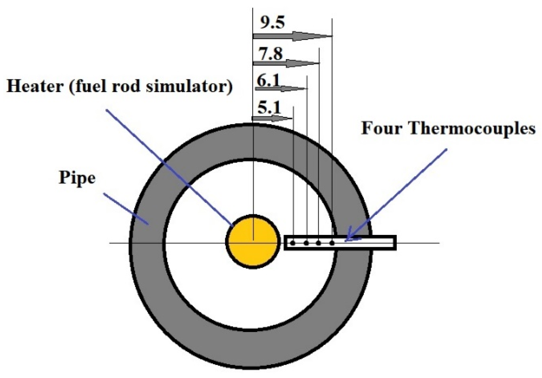
The loop has a testing section which consists of a pipe with a heater rod in the center along the whole testing section of 150 cm total length. The heater itself has a heating section only in 87 cm of its length located after a 60 cm length used for flow development, the heater is then followed by a 3 cm section for device constructional reasons. Four different elevations in the testing section, equally spaced, had four thermocouples each. The temperature of the LBE was calculated in the four elevations based on the average temperature detected by the four thermocouples (
Figure 5).
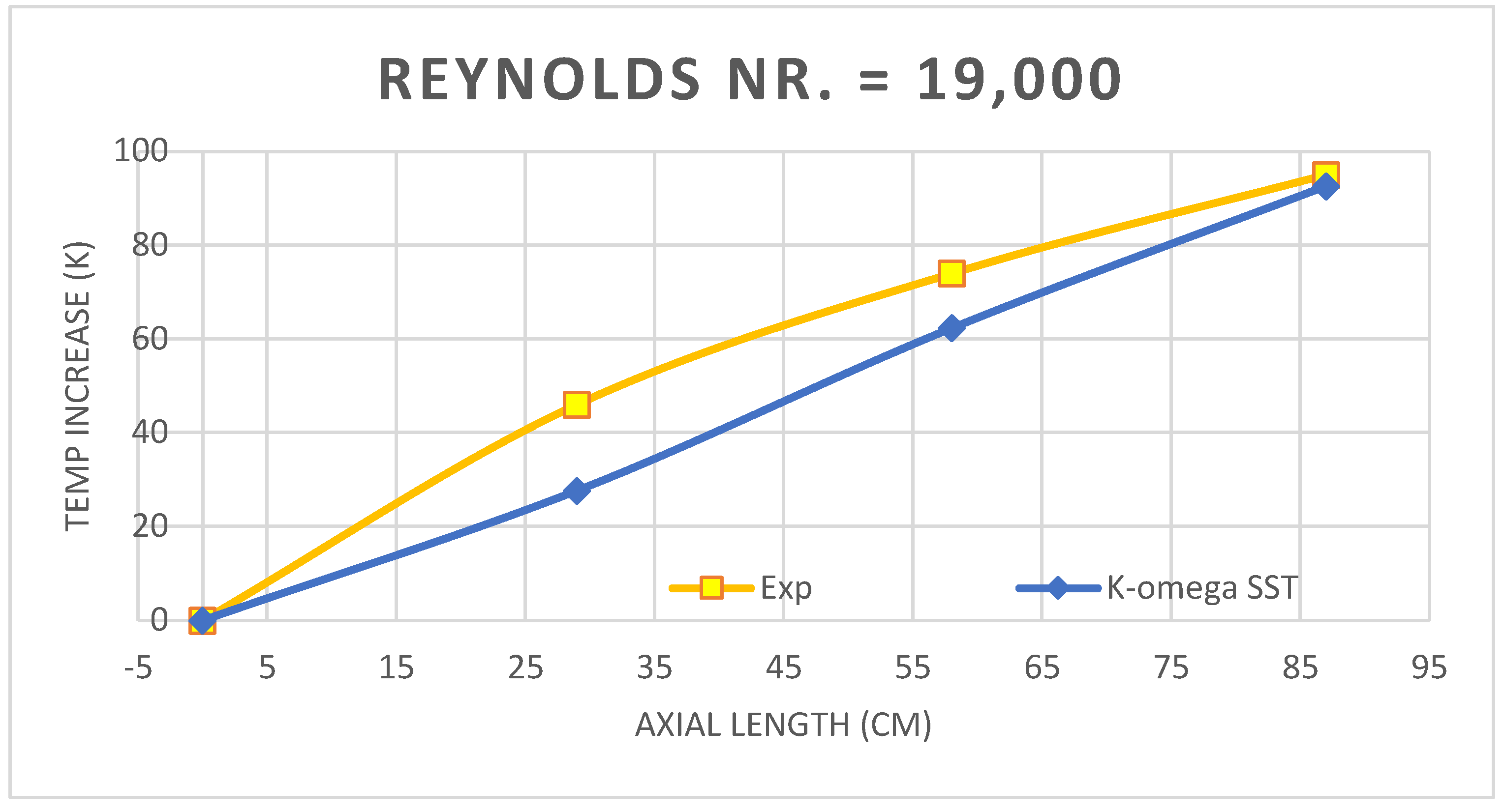
The steady state experiment was set based on the nominal power of the heater, which is 21 kW as a constant value, while different inlet velocities were tested (0.65, 0.93, 1.36, 1.57, and 2 m/s) and temperature increase of the LBE was measured and presented. The lowest and highest Re numbers were selected for modeling for the purpose of validating the k-ω SST model (Re = 19,000 and Re = 61,000). The same elevations as well as thermocouple detection points were modeled with the same dimensions and distances. For this modeling, Ansys fluent was employed and results are presented in
Figure 6 and
Figure 7.
The differences between the used SST k-ω model and the experimental data varied from 0% by the inlet to 3% in the second section in the tested length with highest error value corresponding to the lowest Re number. The error percentage variation within the same sections as well as with Re number variation are presented in
Figure 8.
The results showed that using the SST k-ω model to solve this type of flow with the same or close conditions can be reasonable and leads to robust results. Additionally, the k-ω SST model used a constant turbulent Prandtl number (typically 0.85). An interesting research point is to test using the same model but adding different correlations for the turbulent Prandtl number estimation, hence comparing the results to achieve the highest calculations accuracy. For the forementioned reasons, the SST k-ω model was adopted for further calculations for the MD case studied in this article.
4. Conclusions
In the present work, we applied 3D computational fluid dynamics (CFD) not to the DFR core but to its model “mini demonstrator MD core” to be constructed in order to test the DFR functionality without any radioactivity. The structure of the proposed DFR mini demonstrator has been presented here in detail, encompassing key components and elements of the two loops, such as the core, pump, tanks, and heaters. The core design has been thoroughly described, highlighting the flow patterns of cold and hot fluids through the inlets, outlets, and piping system. The dimensions of the pipes and core vessel are presented, mirroring those of the real DFR, except for the number of pipes which is reduced to the minimum number of seven, reflecting the hexagonal geometry of the core.
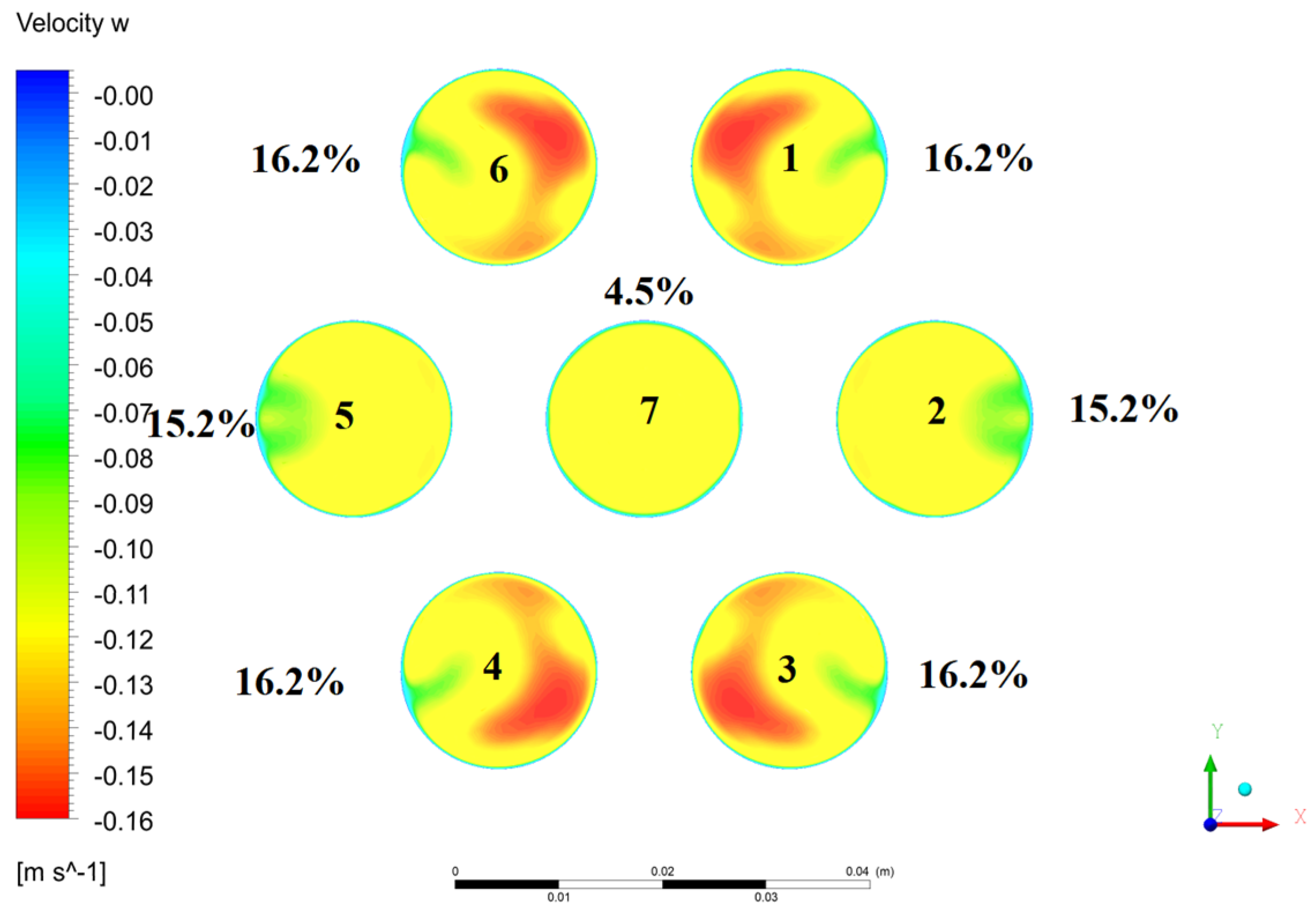
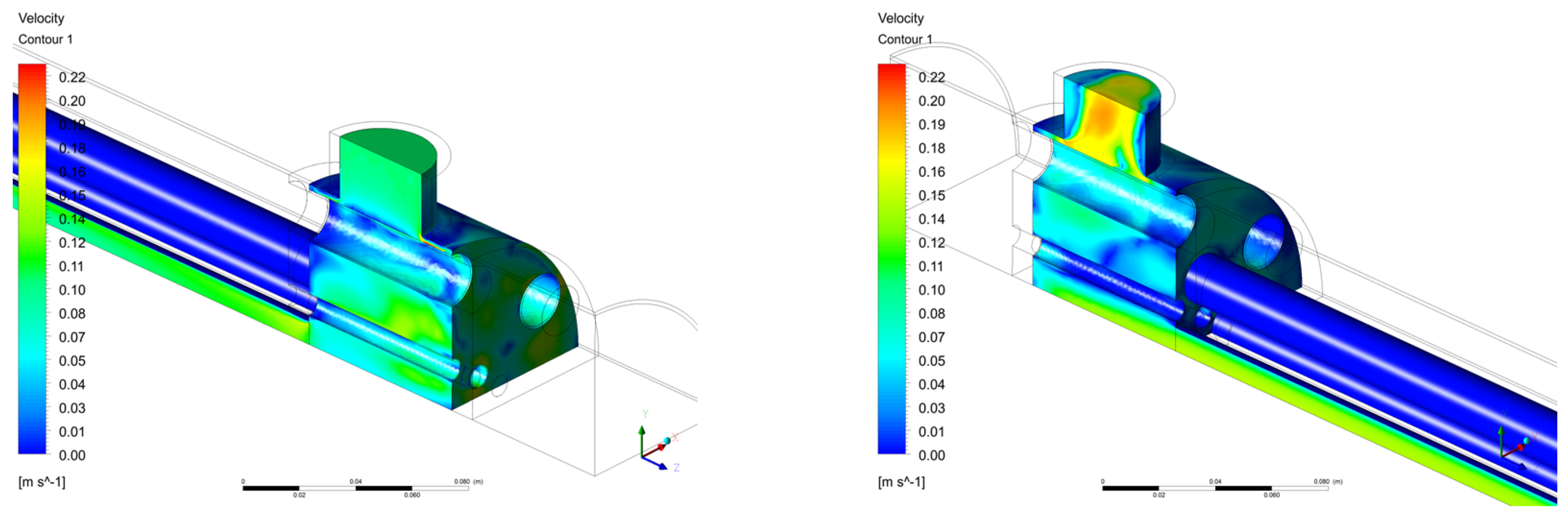
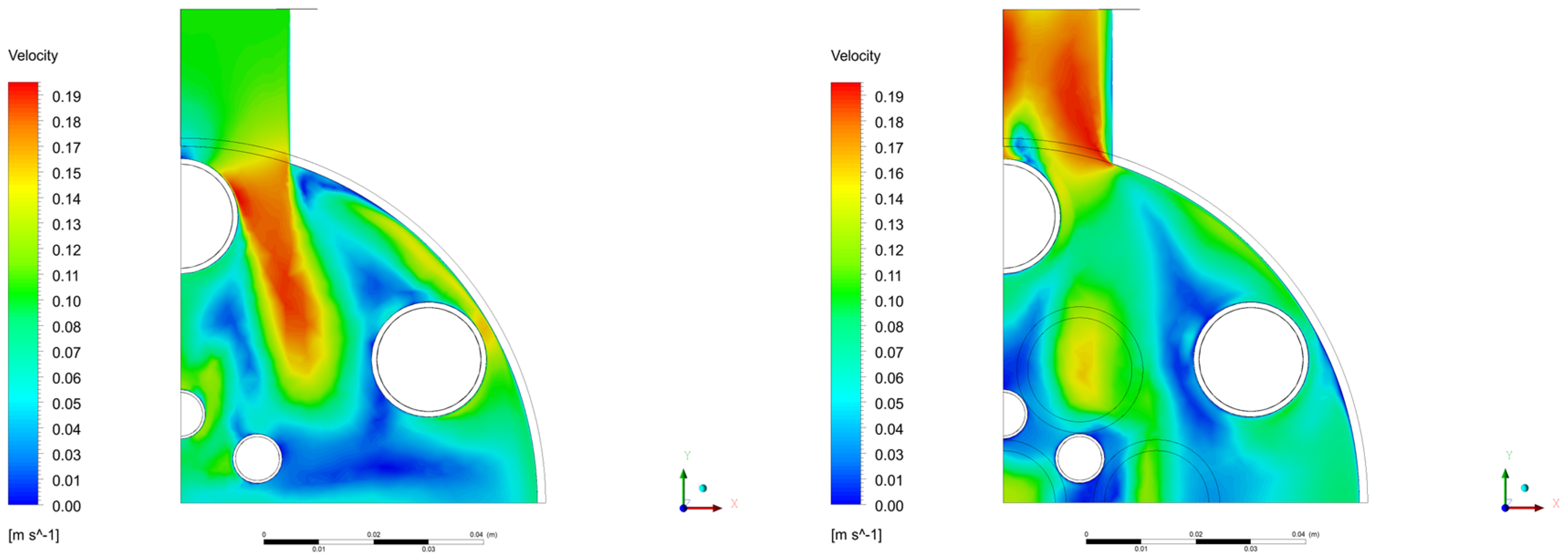
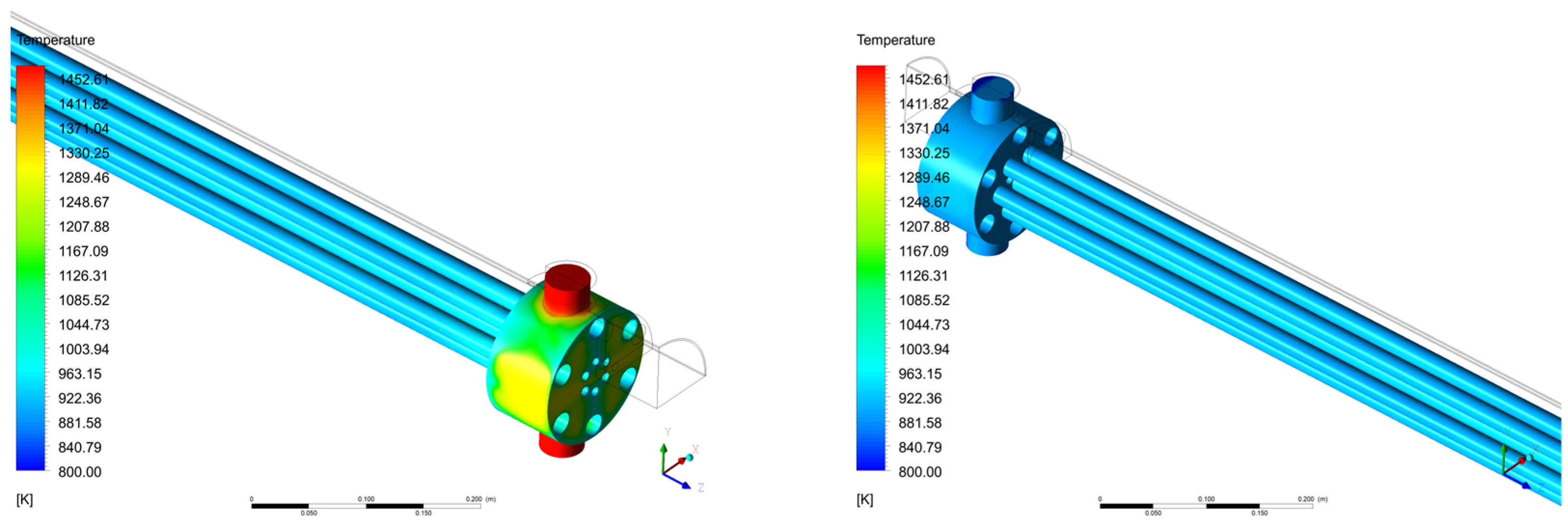
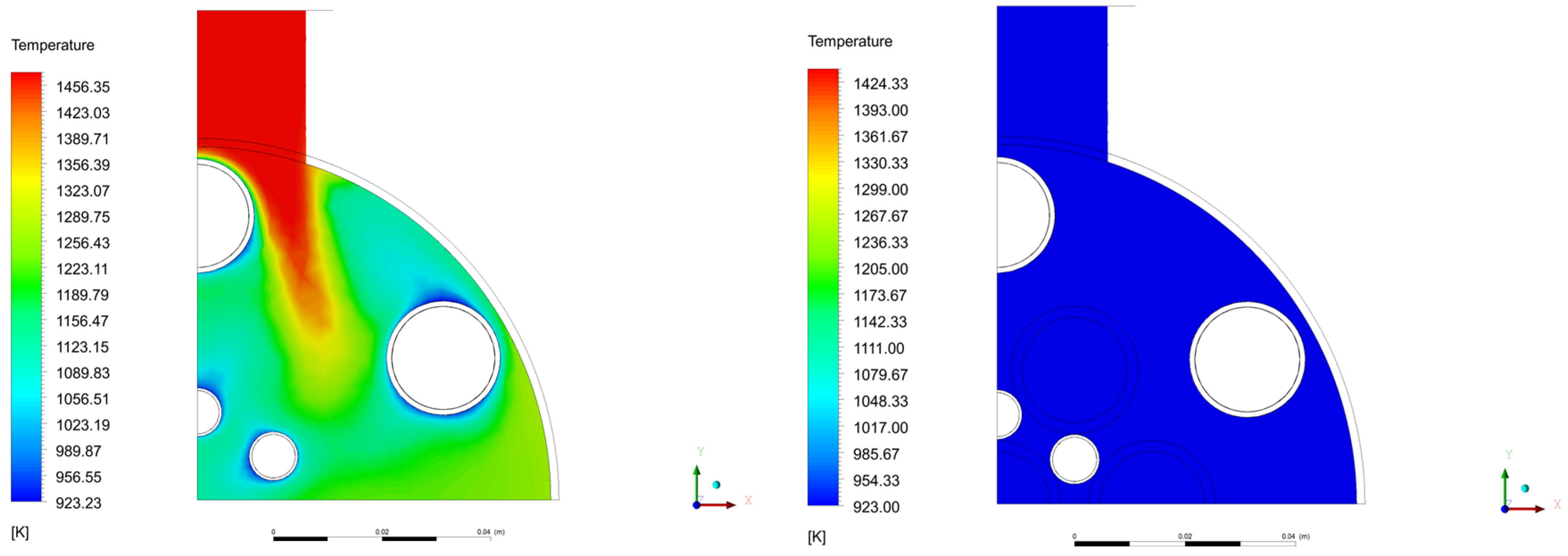
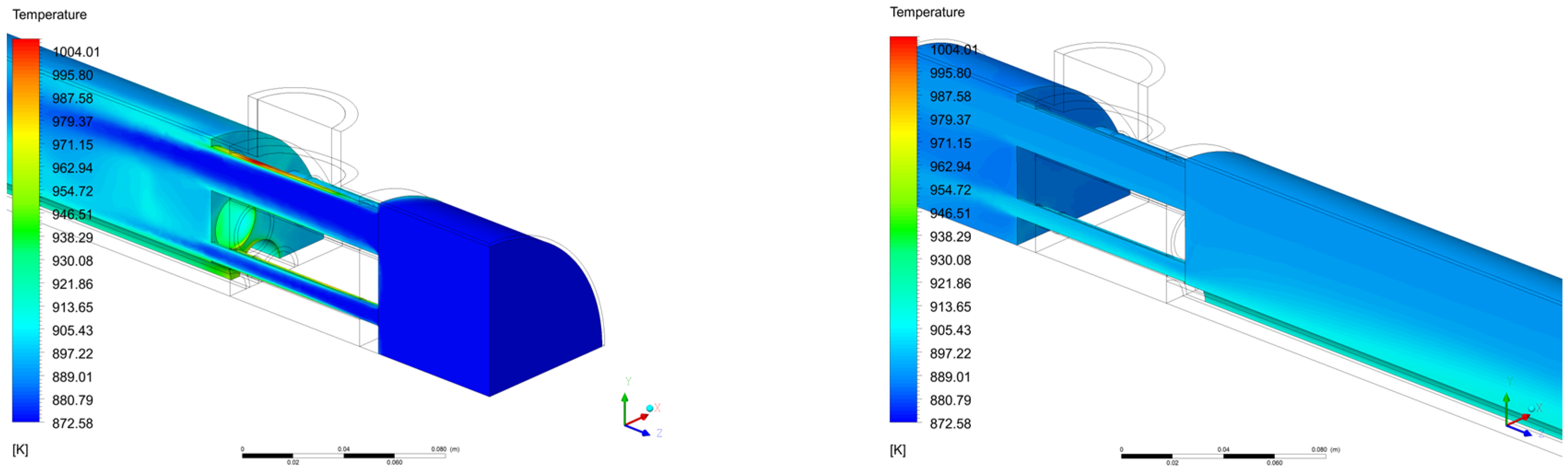
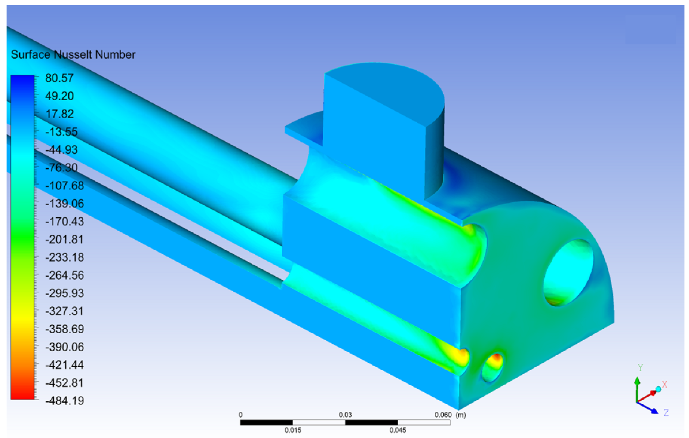
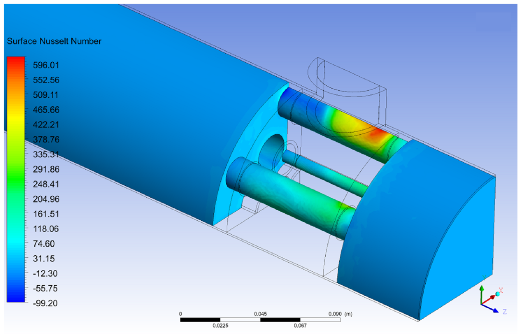
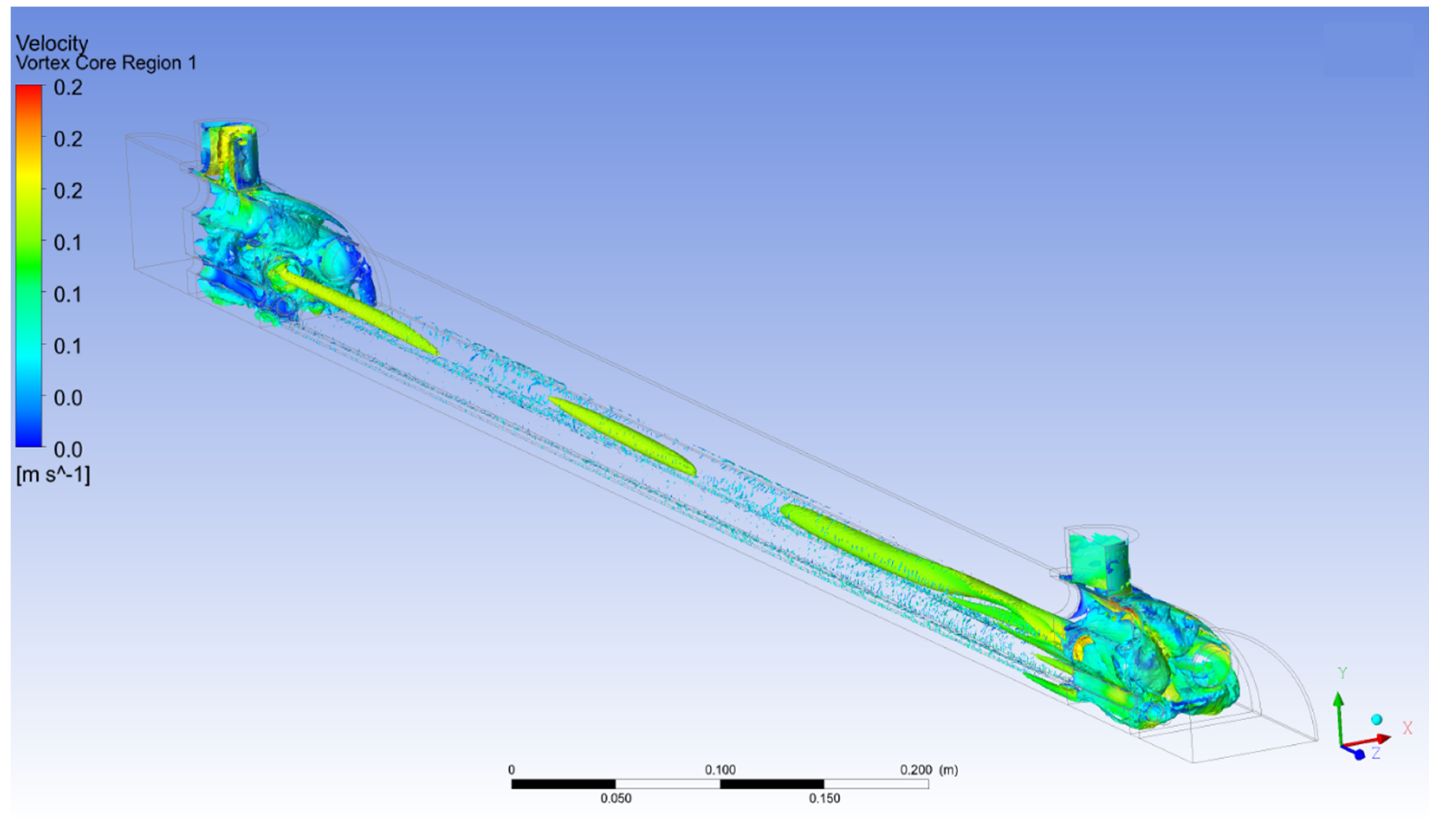
The analysis focused on underlining the heat transfer between the fuel and coolant within the core, considering each pipe individually. Additionally, the mass flow rate for each fuel pipe was determined as a percentage of the total mass flow rate. This analysis showed a lack of uniformity of mass flow distribution percentage per pipe (16–4%). Eddy viscosity and surface Nusselt number contours were employed to identify regions with high heat transfer rates in different areas. The Reynolds numbers, based on mean velocity and hydraulic diameter, ranged from 15,000 to 30,000 for the fuel domain and from 200,000 to 250,000 for the coolant domain. The current design was found to exhibit a rapid increase in turbulence due to intense mixing and abrupt changes in flow areas and directions, despite the relatively low inlet velocities. The analysis conducted in this study revealed significant findings that merit discussion. Firstly, the identification of hot spots in close proximity to the fuel entrance was observed, leading to elevated temperatures within the coolant pipes (up to 1000 K). It is strongly advised to take measures to prevent such occurrences in order to ensure optimal system performance and safety of the reactor. This can be achieved by changing the position of the fuel inlets not to face coolant pipes directly. Furthermore, the mass flow rates within the fuel pipes located in the core exhibited irregular patterns dependent on the pipe’s position. Likewise, variations in heat transfer rates were observed among the different pipes. Flow swirling phenomena were also observed in the fuel pipes, characterized by varying swirling frequencies. These swirling patterns have the potential to induce pipe vibrations, which could lead to fracture under extreme operational conditions. To mitigate these thermal–hydraulic limitations, flow stabilizers can be added, e.g., honeycomb patterns.
Despite the satisfactory agreement obtained for the validation of the k-ω SST model, additional investigations are required for modeling techniques specific to liquid metals. Further validations are crucial for this model. Subsequently, with the construction of the mini demonstrator, additional experimental data can be gathered and compared against various models to identify and address modeling deficiencies and enhance validity. It is also crucial to explore different modeling conditions as different conditions might have different accuracies. Comparison of experimental data with CFD calculations will enable to improve construction of the final design of the reactor.
This study aimed to propose preliminary guidance to the DFR design work and safety analysis, in addition to the validation and future improvements of the model that will be used for both the MD and the DFR to explore optimal design parameters.


