Abstract
Solid-state caloric cooling is a viable route toward a more sustainable way of refrigerating. The refrigerants are solid-state materials with a caloric effect detectable by measuring a temperature variation through an external-field intensity change. The caloric effect could be particularized depending on the properties of the material and the type of field. Magnetocaloric is the effect occurring in ferromagnetic materials through the variation of an external field. Thermodynamically, two are the possible cycles regulating the cooling process in the system: the Active Caloric Regenerative cooling cycle and the solid-to-solid heat transfer (SSHT). The former requires the involvement of an auxiliary fluid for the heat transfer processes; in the latter, the heat transfer can be regulated by thermal diodes with the capability of changing their thermal conductivity depending on the intensity of an external field. The investigation introduced is focused on an SSHT system employing magnetocaloric materials as refrigerants and thermal diodes as the vehiculation elements. The two-dimensionality of the model allows the optimization of the dimensions of both the magnetocaloric and the thermal diode elements to achieve elevated operative frequencies. A comparison between two magnetocaloric materials was performed, Gadolinium and LaFe11.384Mn0.356Si1.26H1.52. Encouraging results on the system, suitably employable in the field of electronic circuit cooling, have been found.
1. Introduction
The electronic components used inside the devices are subjected to a continuous process of evolution and improvement, but the need to ensure proper cooling remains a key aspect for the creation of a successful product. The power dissipation and, therefore, the heat deriving from it are problems that have influenced the development of new devices since the beginning of the research and developments on electronics [1]. Moore’s law requires the number of transistors in integrated circuits to double every two years; this involves a continuous shrinking of the transistors and, together with the increase in the intensity of the current with which they operate, there is an increase in the operating temperatures and in the power density to be dissipated; a phenomenon that, if not controlled well, can lead to breakage of the devices themselves. One of the main points of attention in the design of modern electronic components is the control of working temperatures [2]. High temperatures in the devices affect their operation and performance. From a technological point of view, a good contribution to the theme was given by the techniques of miniaturization of the components that have reduced the power absorption and, consequently, the dissipation. Beyond a certain limit (1 Wcm−2), however, it is necessary to intervene with refrigeration techniques that have found various solutions over time. Among the various solutions are those of the liquid cooling type and, in some cases, over the years, refrigerant fluids, such as freon or, in general, belonging to the class of HCFCs and HFCs, were used [3,4]. However, these fluids are harmful to the environment, both from the point of view of Ozone Depletion and of contribution to global warming. Attention to environmental defense, especially in recent years, was given to the research focused more on eco-sustainable techniques [5,6,7,8,9]. Over the last twenty years, the scientific community has paid greater attention to the alternative and eco-friendly refrigeration technologies based on solid-state refrigerants due to caloric effects [10,11], whose main advantage is the use of solid refrigerant materials, thus avoiding the use of harmful refrigerant fluids. The technological solution of working with solid-state refrigerants represents a great return in terms of environmental impact because they do not present a non-zero global warming potential. The latter, together with the good energy performances, provides the sustainability of the solid-state cooling technology [12] based on the caloric effect, i.e., on the temperature change due to an adiabatic variation of an external field. Caloric systems for cooling or, more specifically, for electronic circuits cooling [13], can be based on an Active Caloric Regenerator (ACR) refrigeration cycle where the solid-state substance acts not only as a refrigerant, providing a temperature variation in the face of adiabatic field increasing or decreasing, but also as a regenerator. Heat transfer processes are regulated through a natural fluid that can be water or air. The main constraints of the ACR cycle are the limitation of the cycle frequency due to the convective heat transfer coefficient between solid and fluid, which influences the cooling capacity. Dually, if the heat transfer processes are, therefore, regulated by solid-state materials, the conductive heat exchange can occur through direct contact with the caloric material that provides a relative motion with them. Otherwise, one can implement solid-state elements with a variable thermal conductivity, i.e., the Thermal Diodes (TD). The thermal diode is an element used to control and manipulate the direction of heat transmission and occasionally its trend since it is able to change its thermal conductivity following the variation of the intensity of an external field [14].
2. State of the Art
Apart from the not-in-kind cooling technologies, such as magnetocaloric [15], many are the fields where the thermal diode concept has found application [16], such as thermal solar [17,18] and photovoltaic [19,20,21,22]. Magnetocaloric is the primarily developed solid-state technology for cooling. The MagnetoCaloric Effect (MCE) is a related phenomenon; thanks to a variable magnetic field (adiabatically) in the influence area of a magnetocaloric material, a temperature mutation is registered in the latter [23,24,25,26,27]. The concept is extendable to other nature fields, e.g., electrical, mechanical (stress or pressure), and applied to caloric materials [14,28,29] with coupling properties, the electrocaloric [30], elastocaloric [31,32], or barocaloric effects [33] are detectable. The employment of thermal diodes as thermal control elements and, more generally, the investigation on solid-to-solid heat transfer (SSHT) caloric systems is very recent, and it began around 12 years ago by Kitanowski and Egwolf [34]. The concept they introduced was referred to as magnetocaloric refrigeration (one of the caloric cooling technologies), but currently, it has been extended to all the other caloric technologies. Magnetocaloric is the first thermal diode-based technology because it has been the pioneering technology among the caloric ones, and it is currently the most consolidated one. Magnetocaloric has found space in many fields of application, such as cryogenic [35] and liquid natural gas production process [36], but the most suitable and investigated field at all is the one for the development of devices for cooling at heat pumping at room temperature. The interest began 35 years ago because of the promising magnetocaloric effect of Gadolinium [37,38] at environmental temperature. The first device, a magnetic heat pump, was developed in 1976 in Ohio (USA) by NASA [39]. The Active Magnetocaloric Regenerative cycle was developed in 1982 [40], consequently to the construction of the Active Magnetic Regenerators (AMR) that were working actively and, at the same time, founding the inverse Brayton cycle. The AMR cycle is the magnetocaloric particularization of the more general ACR cycle introduced in the previous section, and it is proven that regeneration is essential to achieve a higher temperature span. That was a beginning and a breakthrough point of the research in this field that has led to the construction of more than one hundred devices based on the magnetocaloric effect [41], but only a low number of them are based on the SSHT concept. From 2010, the year when the thermal diode concept for caloric cooling was introduced, many studies were disseminated by researchers in the open literature, and almost all were numerical ones. The first application of SSHT with thermal diodes was numerical and introduced in 2012 by Silva et al. [42]. A 1D numerical model based on the finite difference method was presented: the application considered a magnetic refrigeration system founding on thermal diodes and characterized by a layer of magnetocaloric material (Gadolinium under ΔB = 1 T) was placed in the center between two layers of solid-state materials whose conductivity varied within the magnetic field (thermal diodes). This structure is located between two heat exchangers, one hot and one cold. The results gave an optimum point (operation temperature of 296 K), where a maximum cooling power density of 2.75 Wcm−2 and 1.5 as COP was obtained. These results signed the beginning in considering the SSHT with thermal diodes a viable alternative to the AMR cycle. Subsequently, over the years, the same authors have provided updated versions of this model: in 2016, a cascade of Magneto-Caloric Materials (MCM) and thermal diodes was realized [43]. Silva et al. noticed [43] that in thermal diode systems consisting of a cascade of MCM, the temperature span tended to increase with the number of elements of magnetocaloric material until a certain number of them was reached, after which there was a saturation of the performances but toward higher values than the ones achievable with only one element. However, when using many elements, it is possible to reduce the contact time up to very large frequency values. In 2013, Monfared et al. [44] proposed a more complex 1D model where an SSHT system based on Peltier elements as thermal diodes was modeled. The main emerging data showed that, due to Joule heating, it was disadvantageous to try to enhance the cooling power by increasing the electric current in the Peltier elements. Therefore, material properties, optimal parameters, and limitations in fabrications need to be further considered and studied to achieve high performance in practical applications. In 2014, Egolf et al. [45] presented a magnetocaloric heat pump with thermal switches based on Peltier elements formed by thin films of nickel nanowires. The study revealed a good potential for magnetic refrigeration applications, although the thermal resistance, electrical resistance, durability, and cost of Peltier elements are factors that should be further considered. In the same year, Tomc et al. [46] presented the results of an investigation where a numerical comparison between a solid-to-solid magnetocaloric refrigeration device and an AMR cycle was made. The SSHT system is based on micro-Peltier elements as the thermal diodes. The results revealed that the SSHT system allowed to work up to 50–100 Hz as operating frequency rather than 2–3 Hz proper of AMR cycle. However, the exergy efficiency at such high frequencies is not substantially improved. They found a maximum specific cooling power of up to 2 kW kg−1. In contrast with [46], there is the later published work (in 2017) by de Vries et al. [47]. They identify [47] an optimal switching frequency (20–25 Hz), and the influence of different configurations and load variations on system performance was investigated using a 2D simulation. However, the loss of heat through the thermal diode caused a more realistic, not negligible, reduction in performance, and, therefore, the prospect of the application was not so optimistic. In 2017 an enhanced solution for SSHT was proposed by Wu et al. [48] in their study, where they described a new magnetic refrigeration cycle based on the regeneration of micro-units in cascade, which avoids the use of heat transfer fluid and heat flow switching elements. This cycle is defined by the acronym MUR (Micro Unit Regeneration). The novelty is to realize, through a ring structure, a continuous useful effect of heat subtraction from a cold side without the help of the heat transfer fluid, reducing the transfer loss of heat and avoiding intermittent fluid flow. In 2020, Klinar et al. [49] introduced a numerical investigation on a magnetocaloric device based on a thermal diode and devoted to macroscale refrigeration, tested on different materials, and they underlined the great potential of thermal diode technology for cooling applications. In 2019, Hess et al. extended [50] the concept of thermal diodes to the more general caloric class. As a matter of fact, the literature also accounts for experimental prototypes based on SSHT systems, as reviewed by Greco et al. [41]. Next to this, the concept of thermal diodes as solid-state heat transfer material is very recent; there are only two conceptual studies performed, respectively, through ElectroCaloric Effect (ECE) [51] in 2013 and elastocaloric [52] in 2018, as underlined by Klinar and Kitanovski in their review [53]. In 2020, Kalizan and Tušek [54] presented to the scientific community the results of a comparative study between electrocaloric and elastocaloric materials employed as refrigerants of a microscale caloric device based on thermal diodes and devoted to electronic circuits cooling. They found that electrocaloric materials can achieve super enormous COP up to 30–40. The elastocaloric materials are also promising, but they allow to reach COPs up to 10 but specific cooling powers higher than the electrocaloric ones. Nevertheless, many points of improvement are still to be investigated. This paper introduces a comparative study on magnetocaloric materials employed as refrigerants of a TD-SSHT device through the development of a two-dimensional model. This type of study, to the best of our knowledge, has not been performed yet. In this paper, a 2D model of a thermal diode-based SSHT system for controlling the heating of electronic circuits is introduced. The novelties introduced by the development of such a 2D model are the possibility of optimizing the dimensions of both the block of caloric refrigerant and the thermal diodes with the aim of optimizing the heat transfer to reach high values of working frequencies, a comparison among the energy performances given by an SSHT thermal-diode caloric system for cooling employing different solid-state magnetocaloric materials.
3. Physical Phenomenon and Thermodynamic Cycles
The caloric effect can be measured as an adiabatic temperature variation or an isothermal entropy change according to the following relations:
where Y and X are the driving the conjugate fields, respectively. (Y = H, and X = M for magnetocaloric cooling).
The thermodynamic cycle underlying caloric refrigeration is known as an Active Caloric Regenerator refrigeration cycle based on the Brayton one, representing the most investigated cycle in the field of caloric refrigeration at room temperature. The caloric element is active, and the employment of fluid (commonly water or air) allows to vehiculate heat fluxes between the two environments.
ACR is characterized by the following four steps repeated cyclically:
- adiabatic-field increasing;
- heat-releasing toward a Hot Heat Exchanger (HHEX);
- adiabatic-field decreasing;
- heat-subtracting from a Cold Heat Exchanger (CHEX).
An ACR allows reaching a temperature span greater than the maximum ΔTad of the MCM.
Dually, the high pressure in the regenerator leads to large viscous dissipation that reflects on the COP; the limitation of the cycle frequency is due to the convective heat transfer coefficient between solid and fluid, which influences the cooling capacity.
SSHT is the answer to the cons shown by the ACR since the heat transfer is conductive and, so, the achievable frequencies are larger. The steps of the SSHT cycle are visible in Figure 1a,b, and they are as follows:
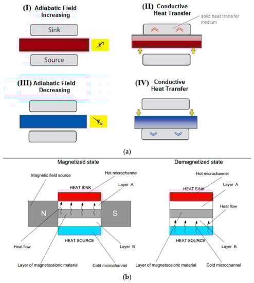
Figure 1.
(a) The SSHT caloric cycle; (b) the solid-to-solid thermal diode-based concept for magnetocaloric cooling [34].
- adiabatic-field increasing;
- conductive-heat transfer with the upper solid-state auxiliary material to release thermal energy toward a hot side;
- adiabatic-field decreasing;
- conductive-heat transfer between the downer solid-state auxiliary material to subtract heat from the cold side.
In (I), the caloric material increases its temperature of ΔTad due to the caloric effect. (II) is the heat transfer process where the caloric material reduces its temperature thanks to a conductive heat exchange with the solid-state auxiliary material. So, the heat is released toward a hot heat exchanger. In (III), the field is decreased adiabatically, and the caloric material furtherly decreases its temperature of ΔTad due to the caloric effect. The (IV) is the stadium where the cooling is achieved thanks to the heat taken from the cold source, occurring through a conductive heat transfer with the secondary solid-state material that is not colder.
If the heat transfer materials are conductive elements, to ensure a controlled heat transfer only in the desired steps of the cycle, an up-and-down motion of the caloric material is required, as visible in Figure 1a, proposed by Kitanovski and Egolf [32]. Another possibility is to design the SSHT system without any relative movements between the caloric material and the conductive elements through the concept of Thermal Diodes (TD), as visible in Figure 1b. The grey block is the magnetocaloric element that is alternatively magnetized and demagnetized. The upper and lower white blocks (Layers A and B) are the thermal diodes, and they show opposite properties: Layer A becomes a thermal conductor if it is magnetized, while magnetization makes Layer B a thermal insulator. Dually, a demagnetization reflects in kB rising and kA falling. Heat flux can flow from CHEX to HHEX without any mechanical motion, realizing the cooling effect. Through this solution, large frequency values are achievable.
4. The 2D Model
The modeled system is constituted by a rectangular block of a caloric material (2 mm thickness × 12 mm height) placed between two thermal diode-type elements (1 mm × 12 mm each): the left one is in contact with the cold heat sink, the right one with the hot source. The three blocks are in contact with each other, so the heat transfer occurs only through conduction. According to this, the mathematical model that regulates the four steps of the thermal diode-based cycle is given only by the energy equations for the three blocks, as reported in the following formula:
where the term Q placed in the energy equation of the caloric refrigerant accounts for the caloric effect. Applying the concept to magnetocaloric cooling, consequently, Q models the magnetocaloric effect experienced by magnetocaloric material, and it is proportional to the adiabatic temperature variation ΔTad due to MCE. It is defined as a density of power generated per unit of volume, which is described by the following relationship:
This Q term is positive in the magnetization phase and negative in the demagnetization phase, and it is placed only in the equation that regulates the operation of the magnetocaloric material, as the diodes do not show the magnetocaloric effect.
For the implementation of the diodes, an active material with thermal conductivity k(H) dependent on the applied magnetic field H is used so that
kA (0) < kB (0) for H = 0
kA (0) + ΔkA > kB (0) for H ≠ 0
According to this, in the proposed mathematical model, the thermal diodes A and B are characterized by time-dependent thermal conductivity and, specifically,
where and are two analytical functions reproducing customized square waves functions to let the thermal conductivities behaving as described in Equations (5) and (6), depending on the magnetization/demagnetization cycles of the SSHT system.
The following boundary conditions represent the CHEAH and HHEAX:
The equation system (3) is solved through a FEM approach; i.e., the domain has been divided into triangular elements, following free triangular meshing.
The resolution of the equations of the FEM model has been achieved through a time-dependent solver that, due to its stability and affordability, utilizes the implicit BDF (Backward Differentiation Formula) as a time-step procedure so as to work with equations presenting accuracy from one (named as the backward Euler method) to five. The optimum in terms of accuracy would be to employ high-order BDF whenever possible and lower-order BDF only when the stability of the resolution must be kept. The latter strategy is called free-time stepping, allowing the solver to set larger or reduced time steps to satisfy the required tolerances. In fact, the solver tries to calculate with the largest possible time step, but when the solution is characterized by high-slope gradients, the relative and absolute tolerances could not be respected anymore, and consequently, the size of the timestep is reduced as required. A sensitivity analysis has been carried out, varying the cycle frequency. The set of frequencies under which the investigation has been performed is the following:
The initial temperature of the system is fixed at 291 K, and 3 K is the temperature difference between the temperatures of the cold and the hot heat exchangers (289.5 K and 292.5 K, respectively).
To characterize the thermal diode, the cooling power density (coupled with the heat adsorbed in the cold heat exchanger), the heating power density (coupled with the heat released toward the hot heat exchanger), and the Coefficient Of Performance have been considered as energy performances, and they were calculated as follows:
The temperature derivative of Equation (12) has been calculated at the interface between the thermal diode A and the magnetocaloric material, whereas the temperature derivative of Equation (13) has been evaluated at the dual interface.
5. Solid-State Materials
For the investigation presented in this paper, many materials have been considered. Two different magnetocaloric materials have been chosen as possible solid-state refrigerants for a thermal diode-based SSHT system. The magnetocaloric are Gadolinium (k = 10.9 W m−1K−1; ρ = 7900 kg m−3) and a specific La-Fe-Si based alloy, i.e., LaFe11.384Mn0.356Si1.26H1.52 (k = 9.0 W m−1K−1; ρ = 7100 kg m−3). The magnetocaloric properties (ΔTad(B,T) and Cp(B,T)) of gadolinium and of LaFe11.384Mn0.356Si1.26H1.52 available from the existing literature [55,56,57,58,59] have been plotted in Figure 2 and Figure 3 through an interpolation software. In Figure 2a and Figure 3a, one can see the adiabatic temperature change measured during magnetization and demagnetization with ΔB = 1.2 T; Figure 2b and Figure 3b report the heat capacity measured during magnetization with ΔB = 1.2 T.
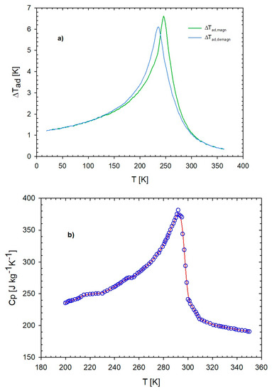
Figure 2.
(a) Adiabatic-temperature change under ΔB = 0–1.2 T and (b) heat capacity of gadolinium measured at 1.2 T (the red line is the interpolation of the blue circle).
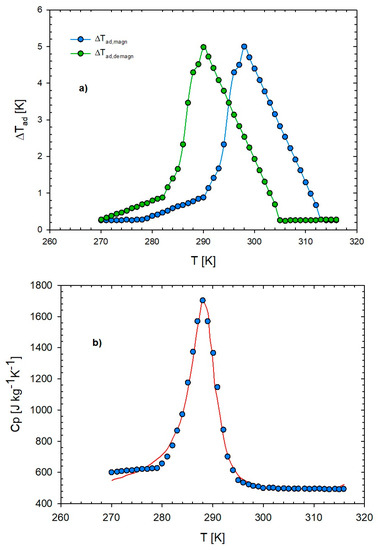
Figure 3.
(a) Adiabatic-temperature change under ΔB = 0–1.2 T and (b) heat capacity of LaFe11.384Mn0.356Si1.26H1.52 measured at 0 T (the red line is the interpolation of blue circles).
To define the Q functions for magnetization and demagnetization processes in Equation (4), a mathematical function finder software, Nutonian Formulize, has been utilized. With the use of this software and the experimental data reported in Figure 2 and Figure 3, mathematical expressions of Cp and Q for both magnetization and demagnetization were found.
6. Results
In Table 1, for both the magnetocaloric materials, the mathematical expressions for the Cp(B,T), Qmagn(B,T), and Qdemagn(B,T), modeling, respectively, the heat capacity vs. T, the magnetocaloric effect during the magnetization and demagnetization steps, under ΔB = 1.2 T, are listed. The values of these expressions have been replaced in the energy equation of the magnetic material given in Equations (3) and (4).

Table 1.
Mathematical expressions of Cp and Q found for the presented materials during magnetization and demagnetization.
Figure 4 and Figure 5 show the interpolated function of (a) Qmagn and (b) Qdemagn, corresponding to the mathematical expressions found for Gadolinium and LaFe11.384Mn0.356Si1.26H1.52, respectively, to model the magnetocaloric effect. Circles represent experimental data, whereas the continuous line is the curve fitting. In all the above-mentioned figures, it is possible to appreciate a peak around the Curie temperature, where the magnetocaloric effect is maximum. For Gd, Qmagn and Qdemagn seem to present the same intensity peak that also follows around the same temperature. This is due to the low magnetic hysteresis shown by gadolinium, which is proper for a second-order transition material; the latter characteristic also ensures that the magnetocaloric effect of gadolinium spreads over a quite large range of temperature (approximately 200 ÷ 350 K). The difference coming out from Figure 5 reflects the first-order magnetic transition nature of the LaFe11.384Mn0.356Si1.26H1.52 that, due to magnetic hysteresis, exhibits peaks of different values (23 M J m−3 for Qmagn and 17 M J m−3 for Qdemagn) falling in correspondence of different temperatures (291 K and 298 K, respectively, for magnetization and demagnetization). The peaks of the two curves for LaFe11.384Mn0.356Si1.26H1.52 are higher, and the MCE is significant in a larger temperature range with respect to Gd.
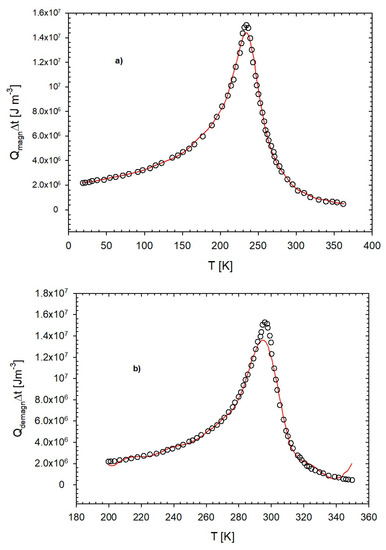
Figure 4.
(a) The functions Qmagn and (b) Qdemagn vs. T under ΔB = 0–1.2 T. (the red line is the interpolation of the circles).
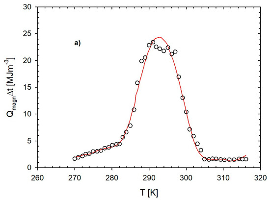
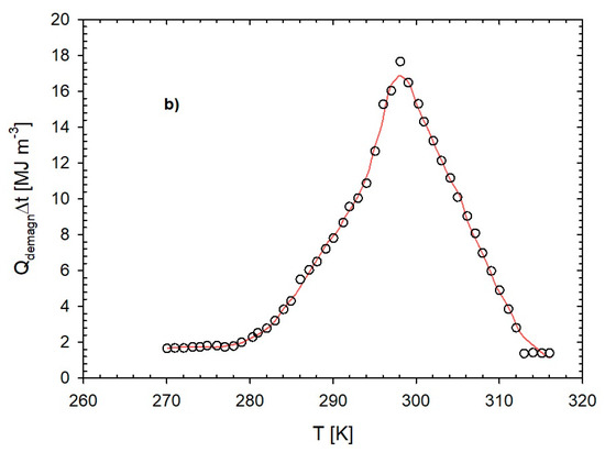
Figure 5.
The functions (a) Qmagn and (b) Qdemagn vs. T under ΔB = 0–1.2 T (the red line is the interpolation of the circles).
After this, the simulation campaign started under the conditions of Section 3. In Figure 6a,b, the cooling power density and the heating power density are reported. Cooling power density is the most important parameter for these SSHT applications. The trends of the curves in Figure 6a related to the reliance of the frequency to the cooling power density, with 2 mm as the fixed thickness of the block of caloric material, reveals that qc increases up to an optimal frequency and then slowly decline. Moreover, from the Figure, two main considerations are emerging:
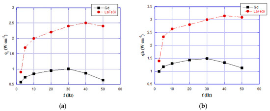
Figure 6.
(a) Cooling power density and (b) heating power density as a function of working frequency for the magnetocaloric materials under test.
- -
- for every material, the peak of qc falls at a different frequency;
- -
- the cooling power evaluated for a thermal diode-based SSHT system working with LaFe11.384Mn0.356Si1.26H1.52 is globally higher than an operation with Gadolinium as a refrigerant.
The cooling power density peak for Gadolinium has been registered at 30 Hz, whereas the LaFe11.384Mn0.356Si1.26H1.52 one falls at 40 Hz. The behavior that sees LaFe11.384Mn0.356Si1.26H1.52 cooling power densities, always greater than gadolinium one, is attributable to the working temperature range (289.5 K–292.5 K) that is better centered around the maximum of the former material. Specifically, the differential increase in the cooling power of the LaFeSi is more contained at low frequencies (56% at 2.5 Hz), while it becomes more and more marked as the increase in frequency, up to a maximum of 272% at 50 Hz. From the results, it emerges that LaFeSi works better at high frequencies. Anyhow, the medium percentage increment of cooling power density, on the whole, investigated frequency range is 150.6%.
Figure 6b plots the heating power density as a function of the working frequency for the magnetocaloric materials under test. The trend shown by the curves reflects one of the cooling powers; Gadolinium has a peak around 30 Hz, whereas the one shown by the heating power is given by LaFe11.384Mn0.356Si1.26H1.52 falls at 40 Hz. The heating power of LaFe11.384Mn0.356Si1.26H1.52, for every frequency, is always greater than the Gd one. Consequently, also the differential increase in the heating power density follows the one of qc, but the calculated values are slightly smaller: the minimum and the maximum increments are 40.0% and 173.1%, respectively, at 2.5 Hz and 50 Hz. The medium percentage increment of on the whole frequency range under investigation is 106.9%.
Figure 7 reports the coefficient of performance as a function of the working frequency for the magnetocaloric materials under test. Both materials show a peak Coefficient of Performance at 30 Hz. The lower values of the cooling power density evaluated for the gadolinium with respect to the tested LaFeSi compound are also reflected in the coefficient of performance. The best COP is 4, and it is calculated for LaFe11.384Mn0.356Si1.26H1.52 at 30 Hz. The percentual increment of COP of LaFe11.384Mn0.356Si1.26H1.52, with respect to Gd on the peak of the curve, is 88.7%. The average COP increment on the whole interval of frequency range under test is 86.5%. The numerical values of the energy performances agree with the scientific literature. Specifically, the qc and COP measured for Gadolinium punctually accord with the results found by Silva et al. [40] in their 1D model, where a maximum cooling power density of 2.75 W cm−2 and 1.5 as COP were obtained for a system working with Gadolinium. The differences between the peak of qc registered in our model (1 W cm−2) and the one of Silva et al. (2.5 W cm−2) lies in the different operating temperature that, in our case (291 K), is not so close to the Curie Temperature of the Gadolinium (294 K), rather than the working temperature of the study of Silva et al. (296 K). Nonetheless, the obtained values of coefficients of performance are larger (or, in the worst cases, comparable) than the mean COPs calculated for thermoelectric-based devices (below 1) [60], indicating SSHT thermal diode as a promising application for future use. Another phenomenon that thoroughly agrees with the relevant open literature is the saturation of the energy performances after a certain frequency, as also noticed by [44]. Specifically, they asserted that due to the saturation phenomenon, it is not convenient to work for frequencies larger than 50 Hz.
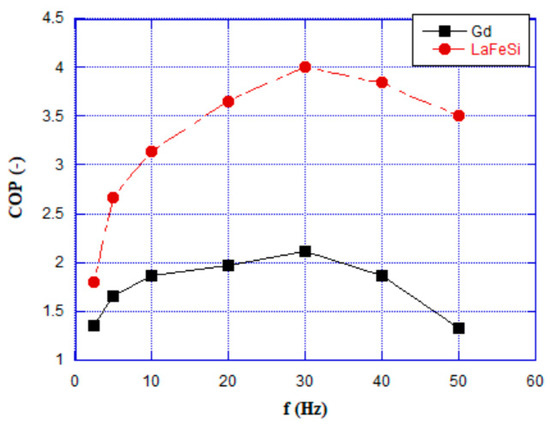
Figure 7.
Coefficient of performance as a function of working frequency for the magnetocaloric materials under test.
7. Conclusions
In this paper, the potentialities of a system based on thermal diodes and employing different caloric-effect materials as refrigerants are analyzed through a 2D numerical model, and a comparison in terms of energy performances is carried out, an investigation that, at the best of our knowledge, has never been analyzed before. In the investigation performed, a comparison between two magnetocaloric materials employable as possible solid-state refrigerants at room temperature have been carried out. This SSHT system is devoted to controlling the heating of electronic circuits, and it could be a starting point for a wider investigation for optimizing other parameters. As a matter of fact, a 2D model allows the possibility of optimizing the dimensions of both the block of caloric refrigerant and the thermal diodes to improve the heat transfer reaching high values of working frequencies.
The coefficients of performance and the cooling powers were evaluated. The general consideration is that the results found are in agreement with other investigations on thermal diode-based SSHT systems published in the open literature. Anyhow, apart from the considerable increase in the working frequency with respect to the caloric cooling systems based on active regeneration and the quite satisfactory energy performances measured (the order of magnitude of the cooling power is in line with or better than the values required for advanced application for cooling of electronic circuits), there are still many points of improvement for this application. Among them, the employment of magnetocaloric materials as refrigerants, given their narrow and peaked ΔTad curves vs. T, does not allow the possibility of working with large temperature ranges. This problem can be overcome with thermal diode-SSHT systems based on other caloric effect materials, such as elastocaloric.
Author Contributions
Conceptualization, L.C., A.G. and C.M.; methodology, L.C., A.G. and C.M.; validation, L.C., A.G. and C.M.; formal analysis, L.C., A.G. and C.M.; investigation, L.C., A.G. and C.M.; data curation, L.C., A.G. and C.M.; writing—original draft preparation, L.C., A.G. and C.M.; writing—review and editing, L.C., A.G. and C.M.; visualization, L.C., A.G. and C.M.; supervision, L.C., A.G. and C.M.; project administration, A.G. All authors have read and agreed to the published version of the manuscript.
Funding
This research received no external funding.
Data Availability Statement
Lead contact: Further information and requests for resources and materials should be directed to and will be fulfilled by the lead contact, Luca Cirillo (luca.cirillo2@unina.it). Materials Availability: This study did not generate new unique materials. Data and code availability: The datasets presented in this study are available from the lead contact upon reasonable request.
Conflicts of Interest
The authors declare no conflict of interest.
Nomenclature
| an | square wave function |
| A | heat exchange surface, m2 |
| B | magnetic field induction, T |
| c | specific heat capacity, J kg−1 K−1 |
| E | electric field, V m−1 |
| f | frequency, Hz |
| H | magnetic field, A m−1 |
| h | convective heat transfer coefficient, W m−2 K−1 |
| K | time dependent thermal conductivity, W m−1 |
| k | thermal conductivity, W m−1 K−1 |
| L | whole length of system, mm |
| M | magnetization, T |
| n | number of times |
| P | polarization, C m−2 |
| p | pressure, Pa |
| power density due to caloric effect, W m−3 | |
| q | thermal power density, W m−2 |
| S | entropy, J kg K |
| T | temperature, K |
| t | time, s |
| V | volume, m3 |
| x | longitudinal spatial coordinate, m |
| X | conjugate field |
| y | orthogonal spatial coordinate, m |
| Y | driving field |
| Greek symbols | |
| Δ | finite difference |
| δ | infinitesimal difference |
| ε | strain, N |
| ξ | infinitesimal quantity |
| ρ | density, kg m−3 |
| σ | uniaxial stress, MPa |
| Subscripts | |
| 0 | initial |
| 1 | final |
| A | thermal Diode A |
| B | thermal Diode B |
| ad | adiabatic |
| C | cold heat exchanger |
| cycle | cycle |
| demagn | demagnetization |
| field | magnetization/demagnetization processes |
| H | hot heat exchanger |
| h | hot |
| M | caloric material |
| magn | magnetization |
| MCM | MagnetoCaloric Material |
| p | constant pressure |
| s | solid |
| TDA | thermal diode A |
| TDB | thermal diode B |
References
- Kish, L.B. End of Moore’s law: Thermal (noise) death of integration in micro and nano electronics. Phys. Lett. A 2002, 305, 144–149. [Google Scholar] [CrossRef]
- Li, C.; Jiao, D.; Jia, J.; Guo, F.; Wang, J. Thermoelectric cooling for power electronics circuits: Modeling and active temperature control. IEEE Trans. Ind. Appl. 2014, 50, 3995–4005. [Google Scholar] [CrossRef]
- Banker, N.D.; Prasad, M.; Dutta, P.; Srinivasan, K. Experimental results of an activated carbon–HFC 134a adsorption cooling system for thermal management of electronics. Appl. Therm. Eng. 2011, 31, 1607–1612. [Google Scholar] [CrossRef]
- Banker, N.D.; Srinivasan, K.; Prasad, M. Performance analysis of activated carbon+ HFC-134a adsorption coolers. Carbon 2004, 42, 117–127. [Google Scholar] [CrossRef]
- Blanco-Marigorta, A.M.; Sanchez-Henríquez, M.V.; Peña-Quintana, J.A. Exergetic comparison of two different cooling technologies for the power cycle of a thermal power plant. Energy 2011, 36, 1966–1972. [Google Scholar] [CrossRef]
- Dorotić, H.; Pukšec, T.; Duić, N. Multi-objective optimization of district heating and cooling systems for a one-year time horizon. Energy 2019, 169, 319–328. [Google Scholar] [CrossRef]
- Brown, J.S.; Domanski, P.A. Review of alternative cooling technologies. Appl. Therm. Eng. 2014, 64, 252–262. [Google Scholar] [CrossRef]
- Qian, S.; Nasuta, D.; Rhoads, A.; Wang, Y.; Geng, Y.; Hwang, Y.; Radermacher, R.; Takeuchi, I. Not-in-kind cooling technologies: A quantitative comparison of refrigerants and system performance. Int. J. Refrig. 2016, 62, 177–192. [Google Scholar] [CrossRef]
- Kitanovski, A.; Plaznik, U.; Tomc, U.; Poredoš, A. Present and future caloric refrigeration and heat-pump technologies. Int. J. Refrig. 2015, 57, 288–298. [Google Scholar] [CrossRef]
- Aprea, C.; Greco, A.; Maiorino, A.; Masselli, C. The environmental impact of solid-state materials working in an active caloric refrigerator compared to a vapor compression cooler. Int. J. Heat Technol. 2018, 36, 1155–1162. [Google Scholar] [CrossRef]
- Aprea, C.; Greco, A.; Maiorino, A.; Masselli, C. Energy performances and numerical investigation of solid-state magnetocaloric materials used as refrigerant in an active magnetic regenerator. Therm. Sci. Eng. Prog. 2018, 6, 370–379. [Google Scholar] [CrossRef]
- Aprea, C.; Greco, A.; Maiorino, A.; Masselli, C. Enhancing the heat transfer in an active barocaloric cooling system using ethylene-glycol based nanofluids as secondary medium. Energies 2019, 12, 2902. [Google Scholar] [CrossRef]
- Cirillo, L.; Greco, A.; Masselli, C. Development of an electronic circuit cooling system using elastocaloric effect: A FEM comparison among different configurations. Appl. Therm. Eng. 2023, 219, 119463. [Google Scholar] [CrossRef]
- Moya, X.; Kar-Narayan, S.; Mathur, N.D. Caloric materials near ferroic phase transitions. Nat. Mater. 2014, 13, 439–450. [Google Scholar] [CrossRef] [PubMed]
- Wang, Y.; Wang, H.; Tan, W.; Huo, D. Magnetization reversal, critical behavior, and magnetocaloric effect in NdMnO3: The role of magnetic ordering of Nd and Mn moments. J. Appl. Phys. 2022, 132, 183907. [Google Scholar] [CrossRef]
- Wong, M.Y.; Tso, C.Y.; Ho, T.C.; Lee, H.H. A review of state of the art thermal diodes and their potential applications. Int. J. Heat Mass Transf. 2021, 164, 120607. [Google Scholar] [CrossRef]
- Smyth, M.; Barone, G.; Buonomano, A.; Forzano, C.; Giuzio, G.F.; Palombo, A.; Mondol, J.; Muhumuza, R.; Pugsley, A.; Zacharopoulos, A.; et al. Modelling and experimental evaluation of an innovative integrated collector storage solar water heating (ICSSWH) prototype. Renew. Energy 2020, 157, 974–986. [Google Scholar] [CrossRef]
- Teymori-omran, M.; Motevali, A.; Seyedi, S.R.M.; Montazeri, M. Numerical simulation and experimental validation of a photovoltaic/thermal system: Performance comparison inside and outside greenhouse. Sustain. Energy Technol. Assess. 2021, 46, 101271. [Google Scholar] [CrossRef]
- Gholami, A.; Ameri, M.; Zandi, M.; Ghoachani, R.G. A single-diode model for photovoltaic panels in variable environmental conditions: Investigating dust impacts with experimental evaluation. Sustain. Energy Technol. Assess. 2021, 47, 101392. [Google Scholar] [CrossRef]
- Gholami, A.; Ameri, M.; Zandi, M.; Ghoachani, R.G. Electrical, thermal and optical modeling of photovoltaic systems: Step-by-step guide and comparative review study. Sustain. Energy Technol. Assess. 2022, 49, 101711. [Google Scholar] [CrossRef]
- Elminshawy, N.A.; Osama, A.; Naeim, N.; Elbaksawi, O.; Tina, G.M. Thermal regulation of partially floating photovoltaics for enhanced electricity production: A modeling and experimental analysis. Sustain. Energy Technol. Assess. 2022, 53, 102582. [Google Scholar] [CrossRef]
- Abd Elaziz, M.; Almodfer, R.; Ahmadianfar, I.; Ibrahim, I.A.; Mudhsh, M.; Abualigah, L.; Lu, S.; Abd El-Latif, A.A.; Yousri, D. Static models for implementing photovoltaic panels characteristics under various environmental conditions using improved gradient-based optimizer. Sustain. Energy Technol. Assess. 2022, 52, 102150. [Google Scholar] [CrossRef]
- Aprea, C.; Greco, A.; Maiorino, A.; Masselli, C. A comparison between electrocaloric and magnetocaloric materials for solid state refrigeration. Int. J. Heat Technol. 2017, 35, 225–234. [Google Scholar] [CrossRef]
- Aprea, C.; Greco, A.; Maiorino, A.; Masselli, C. Analyzing the energetic performances of AMR regenerator working with different magnetocaloric materials: Investigations and viewpoints. Int. J. Heat Technol. 2017, 35, S383–S390. [Google Scholar] [CrossRef]
- De Oliveira, N.A.; von Ranke, P.J. Theoretical aspects of the magnetocaloric effect. Phys. Rep. 2010, 489, 89–159. [Google Scholar] [CrossRef]
- Pecharsky, V.K.; Gschneidner, K.A., Jr. Magnetocaloric effect and magnetic refrigeration. J. Magn. Magn. Mater. 1999, 200, 44–56. [Google Scholar] [CrossRef]
- Zhao, B.; Hu, X.; Dong, F.; Wang, Y.; Wang, H.; Tan, W.; Huo, D. The Magnetic Properties and Magnetocaloric Effect of Pr0.7Sr0.3MnO3 Thin Film Grown on SrTiO3 Substrate. Materials 2023, 16, 75. [Google Scholar] [CrossRef]
- Moya, X.; Mathur, N.D. Caloric materials for cooling and heating. Science 2020, 370, 797–803. [Google Scholar] [CrossRef]
- Aprea, C.; Greco, A.; Maiorino, A. A numerical analysis of an active magnetic regenerative cascade system. Int. J. Energy Res. 2011, 35, 177–188. [Google Scholar] [CrossRef]
- Aprea, C.; Greco, A.; Maiorino, A.; Masselli, C. A comparison between different materials in an active electrocaloric regenerative cycle with a 2D numerical model. Int. J. Refrig. 2016, 69, 369–382. [Google Scholar] [CrossRef]
- Yuan, L.; Wang, Y.; Yu, J.; Greco, A.; Masselli, C.; Qian, S. Numerical study of a double-effect elastocaloric cooling system powered by low-grade heat. Appl. Therm. Eng. 2023, 218, 119302. [Google Scholar] [CrossRef]
- Cirillo, L.; Farina, A.R.; Greco, A.; Masselli, C. The optimization of the energy performances of a single bunch of elastocaloric elements to be employed in an experimental device. Therm. Sci. Eng. Prog. 2022, 27, 101152. [Google Scholar] [CrossRef]
- Aprea, C.; Greco, A.; Maiorino, A.; Masselli, C. The use of barocaloric effect for energy saving in a domestic refrigerator with ethylene-glycol based nanofluids: A numerical analysis and a comparison with a vapor compression cooler. Energy 2020, 190, 116404. [Google Scholar] [CrossRef]
- Kitanovski, A.; Egolf, P.W. Innovative ideas for future research on magnetocaloric technologies. Int. J. Refrig. 2010, 33, 449–464. [Google Scholar] [CrossRef]
- Falsaperna, M.; Saines, P.J. Development of magnetocaloric coordination polymers for low temperature cooling. Dalton Trans. 2022, 51, 3394–3410. [Google Scholar] [CrossRef]
- Ansarinasab, H.; Hajabdollahi, H.; Fatimah, M. Conceptual design of LNG regasification process using liquid air energy storage (LAES) and LNG production process using magnetic refrigeration system. Sustain. Energy Technol. Assess. 2021, 46, 101239. [Google Scholar] [CrossRef]
- Gschneidner, K.A., Jr.; Pecharsky, V.K. Magnetocaloric materials. Annu. Rev. Mater. Sci. 2000, 30, 387–429. [Google Scholar] [CrossRef]
- Sari, O.; Balli, M. From conventional to magnetic refrigerator technology. Int. J. Refrig. 2014, 37, 8–15. [Google Scholar] [CrossRef]
- Brown, G.V. Magnetic heat pumping near room temperature. J. Appl. Phys. 1976, 47, 3673–3680. [Google Scholar] [CrossRef]
- Barclay, J.A.; Steyert, W.A. Active magnetic regenerator. U.S. Patent No. 4332135, 1 June 1982. [Google Scholar]
- Greco, A.; Aprea, C.; Maiorino, A.; Masselli, C. A review of the state of the art of solid-state caloric cooling processes at room-temperature before 2019. Int. J. Refrig. 2019, 106, 66–88. [Google Scholar] [CrossRef]
- Silva, D.J.; Bordalo, B.D.; Pereira, A.M.; Ventura, J.; Araújo, J.P. Solid state magnetic refrigerator. Appl. Energy 2012, 93, 570–574. [Google Scholar] [CrossRef]
- Silva, D.J.; Bordalo, B.D.; Puga, J.; Pereira, A.M.; Ventura, J.; Oliveira, J.C.R.E.; Araújo, J.P. Optimization of the physical properties of magnetocaloric materials for solid state magnetic refrigeration. Appl. Therm. Eng. 2016, 99, 514–517. [Google Scholar] [CrossRef]
- Monfared, B. Simulation of solid-state magnetocaloric refrigeration systems with Peltier elements as thermal diodes. Int. J. Refrig. 2017, 74, 324–332. [Google Scholar] [CrossRef]
- Egolf, P.W.; Gravier, L.; Francfort, T.; Pawlowski, A.G.; Courret, G.; Croci, M. High-frequency magnetocaloric modules with heat gates operating with the Peltier effect. Int. J. Refrig. 2014, 37, 176–184. [Google Scholar] [CrossRef]
- Tomc, U.; Tušek, J.; Kitanovski, A.; Poredoš, A. A numerical comparison of a parallel-plate AMR and a magnetocaloric device with embodied micro thermoelectric thermal diodes. Int. J. Refrig. 2014, 37, 185–193. [Google Scholar] [CrossRef]
- de Vries, W.; van der Meer, T.H. Application of Peltier thermal diodes in a magnetocaloric heat pump. Appl. Therm. Eng. 2017, 111, 377–386. [Google Scholar] [CrossRef]
- Wu, J.; Lu, B.; Liu, C.; He, J. A novel cascade micro-unit regeneration cycle for solid state magnetic refrigeration. Appl. Therm. Eng. 2018, 137, 836–847. [Google Scholar] [CrossRef]
- Klinar, K.; Muñoz Rojo, M.; Kutnjak, Z.; Kitanovski, A. Toward a solid-state thermal diode for room-temperature magnetocaloric energy conversion. J. Appl. Phys. 2020, 127, 234101. [Google Scholar] [CrossRef]
- Hess, T.; Maier, L.M.; Corhan, P.; Schäfer-Welsen, O.; Wöllenstein, J.; Bartholomé, K. Modelling cascaded caloric refrigeration systems that are based on thermal diodes or switches. Int. J. Refrig. 2019, 103, 215–222. [Google Scholar] [CrossRef]
- Sato, W. A Study of a New Cooling Device Based on the Electrocaloric Effect. In Proceedings of the ASME International Mechanical Engineering Congress and Exposition, San Diego, CA, USA, 15–21 November 2013; Volume 56352, p. V08BT09A002. [Google Scholar]
- Bartholome, K.; Fitger, A.; Mahlke, A.; Winkler, M.; Schaefer-Welsen, O. An elastocaloric cooling system based on latent heat transfer. In Proceedings of the Symposium TP01: Caloric Materials for Highly Efficient Cooling Applications, Boston, MA, USA, 25–30 November 2018. [Google Scholar]
- Klinar, K.; Kitanovski, A. Thermal control elements for caloric energy conversion. Renew. Sustain. Energy Rev. 2020, 118, 109571. [Google Scholar] [CrossRef]
- Kalizan, J.; Tušek, J. Caloric Micro-Cooling: Numerical modelling and parametric investigation. Energy Convers. Manag. 2020, 225, 113421. [Google Scholar] [CrossRef]
- Dan’Kov, S.Y.; Tishin, A.M.; Pecharsky, V.K.; Gschneidner, K.A. Magnetic phase transitions and the magnetothermal properties of gadolinium. Phys. Rev. B 1998, 57, 3478. [Google Scholar] [CrossRef]
- Griffel, M.; Skochdopole, R.E.; Spedding, F.H. The heat capacity of gadolinium from 15 to 355 K. Phys. Rev. 1954, 93, 657. [Google Scholar] [CrossRef]
- Morrison, K.; Sandeman, K.G.; Cohen, L.F.; Sasso, C.P.; Basso, V.; Barcza, A.; Katter, M.; Moore, J.D.; Skokov, K.P.; Gutfleisch, O. Evaluation of the reliability of the measurement of key magnetocaloric properties: A round robin study of La (Fe, Si, Mn) Hδ conducted by the SSEEC consortium of European laboratories. Int. J. Refrig. 2012, 35, 1528–1536. [Google Scholar] [CrossRef]
- Aprea, C.; Greco, A.; Maiorino, A.; Masselli, C. A comparison between rare earth and transition metals working as magnetic materials in an AMR refrigerator in the room temperature range. Appl. Therm. Eng. 2015, 91, 767–777. [Google Scholar] [CrossRef]
- Masselli, C. Magnetic Refrigeration: An Attraction toward Our Future. Ph.D. Thesis, University of Salerno, Fisciano, Italy, 2017. [Google Scholar]
- Min, G.; Rowe, D.M. Experimental evaluation of prototype thermoelectric domestic-refrigerators. Appl. Energy 2006, 83, 133–152. [Google Scholar] [CrossRef]


Disclaimer/Publisher’s Note: The statements, opinions and data contained in all publications are solely those of the individual author(s) and contributor(s) and not of MDPI and/or the editor(s). MDPI and/or the editor(s) disclaim responsibility for any injury to people or property resulting from any ideas, methods, instructions or products referred to in the content. |
© 2023 by the authors. Licensee MDPI, Basel, Switzerland. This article is an open access article distributed under the terms and conditions of the Creative Commons Attribution (CC BY) license (https://creativecommons.org/licenses/by/4.0/).