Abstract
Centrifugal pumps are the most common machines responsible for the increase in hydraulic energy in a piping system. Their proper design, operation, and maintenance have a strong influence on the performance of technological processes carried out in many industrial units. For the ultra-low specific speed (nq < 10) application, there is no economical reason for these pumps to be used. This is caused by an increase in internal losses in the pump. The article concerns the problem of the hydraulic operation of a new type of labyrinth pump—the radial labyrinth pump (RLP), which is a developed axial unit. The main research method involves the experimental research of hydraulic sets consisting of passive and active discs. The analyses were preceded by dimensional analysis and experimental planning. The study investigates the influence of a chosen structural parameter of both discs on the process of energy conversion obtained in the pump. The influence of parameters such as number, depth and width of the grooves, as well as inlet angle and diameter on the properties of the pump was studied and discussed in detail. The essential novelty of the article is the recognition of the hydraulic performance of the RLP with grooved discs. To extend the scope of the conducted research for the chosen hydraulic sets, a comparison of the mutual cooperation of an active disc with a smooth and grooved passive one was conducted. It was identified that not every geometric relationship of the parameters of the active and passive discs results in an increase in head with respect to cooperation with a smooth passive disc (motionless). The highest head and high efficiencies were obtained for sets with short channels with large inlet diameters—zk12 and zk13—ratios for zk12 d1ap/d2ap = 0.78, and for zk13 zk12 d1ap/d2ap = 0.81. Based on the obtained results, preliminary recommendations for the construction were made.
1. Introduction
The range of application of a rotodynamic pump is strongly limited by specific speed nq. It is commonly known that the boundary value of parameter nq is equal to 10. This is due to the economical factors associated with the application of centrifugal pumps [1]. Below this value, due to internal losses, the external efficiency of the pump becomes lower, and its value reduces with the decrease in nq. Moreover, the described problem becomes more complicated when the flow capacity of the pump is lower than Q < 10 m3/h. The presented scope of the parameters is met by positive displacement pumps that have a very high total efficiency. However, in many situations, it is important to secure the following features: low pulsation of the flow parameters, high reliability and durability, lack of connection of the cooperating parts, lack of internal seals, etc. In these situations, centrifugal pumps are one of the solutions. The above-mentioned reasons forced the development of an unusual construction of the flow passages of pumps. Examples of these constructions could be found in the patents database [2,3,4,5] and literature: radial impellers equipped with straight blades [6,7,8], holes, and pipe impellers [9,10].
One potential hydraulic structure that could be applied in the described situations is a labyrinth pump. This type of pump was patented by I. A Golubev [11] and was developed as the concept of a labyrinth seal. The analyzed pump is characterized by the lack of a typical impeller as the element responsible for the increase in the moment of momentum as in a classical centrifugal pump. The hydraulic power is generated by means of the mutual cooperation between two main elements: a motionless sleeve and a rotational cylinder. Both elements are equipped with a multiple thread, where a right-hand thread is located on the moveable element, and a left-hand thread on a stationary one (or vice versa, then the rotation direction is the opposite).
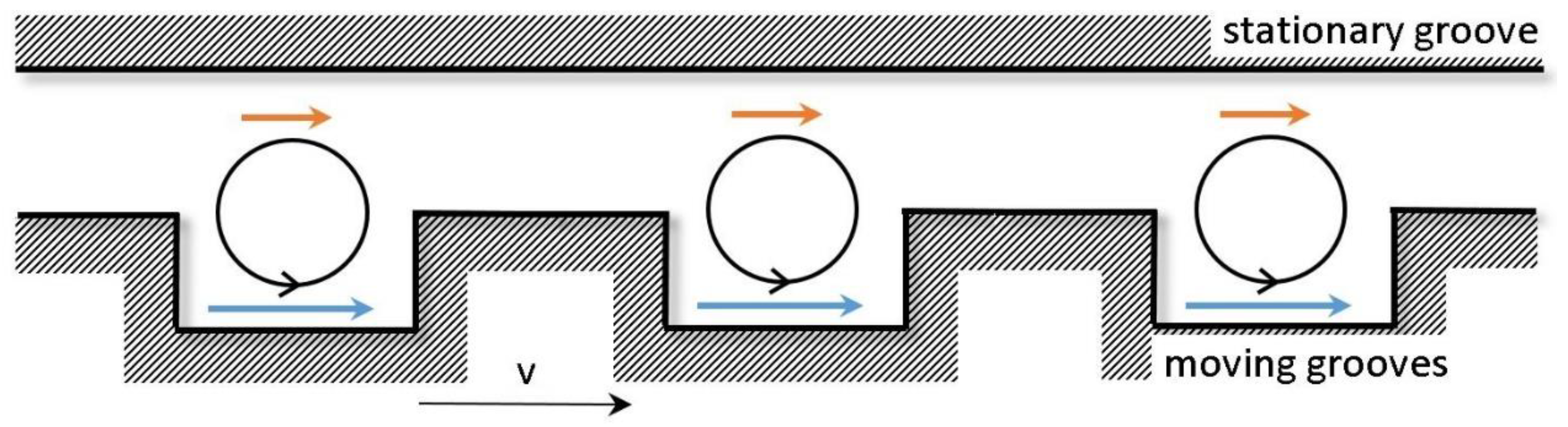
The working process of the labyrinth pump is similar to that observed in side channel pumps. The interaction between the stator and rotor leads to the increase in momentum of the fluid [12,13,14,15]. This process is fulfilled by the impact between the fluid aligned to the motionless and rotational part of the pump. The role of a side channel takes the grooves of the stationary sleeve, and the blades of the impeller can be found in the hills of the rotating thread located on the cylinder. In the cross-section, defined by the grooves of the motionless and rotating element, the vortex structure is observed, which transports the momentum from the active side to the passive one (Figure 1). As a result of the described movement, the total head of the pump increases.
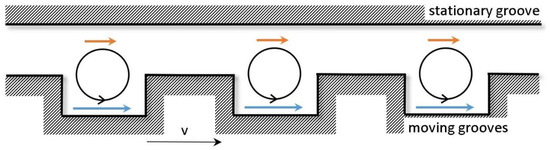
Figure 1.
The working process of the labyrinth pump.
The calculation process of the axial units involves two methods. The first one allows the assumed hydraulic parameters to be obtained by means of recalculating the existing and investigated pumps. As was mentioned in [12], labyrinth pumps are subjected to the law of hydraulic similarity. This approach provides good results and is recommended for practical applications. In the second method, which is based on theoretical calculations, the Prandtl equation for tangent tension in the transverse movement of fluid is applied. The theory, which was first introduced in [12] and then developed in [13,14,16,17,18,19,20,21,22,23,24,25,26,27], correlates theoretical curves with reality by applying the head coefficient k. This factor depends on the shape of the thread: height, width, pitch, angle between the threads of the sleeve and cylinder, clearance between those elements, Reynolds number, and the type of pumped fluid (for slurries). Such a number of parameters means that the determination of the k value is only possible using experimental methods [11,13,14,16,17]. Moreover, the head coefficient also depends on the flow. The application of the parameter k allows the characteristic curves of the pump to be calculated with a convergence to reality equal to 10%. Many researchers focused on the groove design parameters and their impact on the pump performance [28,29,30]. In [21], the authors drew the conclusion that the application of a rectangular labyrinth pump is appropriate for multiphase and high viscous flows. Instead of fluid parameters, structural optimization was analyzed in few studies [25,31,32]. The validation of the numerical modelling was carried out in [33,34], where the rectangular labyrinth pump was compared with the results of the CFD analysis.
Depending on the flow direction, two types of labyrinth pumps can be distinguished: radial labyrinth pumps (RLP) and axial labyrinth pumps (ALP). The RLP is the new approach for labyrinth pumps, as is the case with axial units, and consists of a stationary element, a passive disc, and a rotating element, an active disc (names proposed by the authors). Both discs are equipped with specially designed grooves that have the opposite trajectory for separated discs (Figure 2). Mutual cooperation between the discs, which are separated by clearance δ, results in an increase in the total energy of the flow, which is caused by the superposition of a centrifugal action (the increase in the moment of momentum) and the exchange of momentum. Considering the cross-section perpendicular to the axis of the groove in active disc, two zones can be distinguished: the flat space between adjacent grooves (flatland) and the channel of groove (valley). The first one exchanges the momentum, and the second is mostly responsible for the centrifugal action.
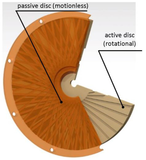
Figure 2.
Isometric view of cooperating discs.
A review of the literature on labyrinth pumps showed that only axial units are recognized, and therefore the investigation of radial pumps seems justified. It is very important to analyze the pumps from a hydraulic point of view, especially in terms of identifying the influence of the geometry of both operating discs on the obtained operating parameters, which is the main motivation of study. In order to design such hydraulic sets in a conscious and sensible way, the mentioned relations should be taken into consideration. Moreover the proposed pump could find the application in different industries, especially the chemical, metallurgical, petrochemical, and food industry, and especially when the pumping process needs to be combined with mixing processes. For Q = 0, the RLP operate as the non-contact, dynamic seal—the other potential application.
2. Object of the Research
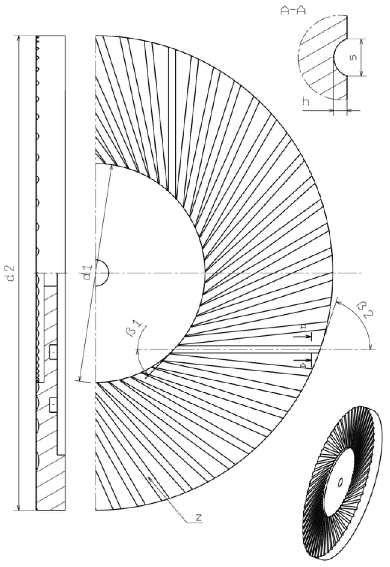
The investigation of the performance of the RLP was preceded by the analysis of the potential geometrical parameters that may have an impact on the performance of the pump. Dimensional analysis was applied as the main tool. The literature review and preliminary studies conducted by the authors allowed for the determination of the following group of parameters that determine the geometry of the operating disc: outer diameter d2, inlet diameter d1, clearance between discs δ, inlet angle of groove β1, outlet angle of groove β2, number of groves z, height h, and width of groove s. In Figure 3, the global dimensions of RLP were presented.

Figure 3.
Geometrical parameters of the cross-section of the grooves.
Specific energy generated by the pump as a product of head and gravity acceleration is equal to:
Y = gH = f(Q, P, ρ, v, n, d2, d1, δ, h, s, β1, β2, z).
In accordance with [6,35], the dimensional independent parameter for the centrifugal pump should be assumed as density ρ, rotational speed n, and the outer diameter of both discs d2. Taking into account the mentioned assumptions, the following formula was obtained:
The first three numbers, according to hydraulic similarity, influence the performance of the labyrinth pump. This was confirmed for the axial and radial units [12,13]. For further analyses, steady pump operation conditions were suggested, and it was assumed that the discharge, power consumption, and viscosity of the pumped medium would be constant. The mentioned simplifications allow function (2) to be reduced to:
To decrease the number of variables, and therefore reduce the experimental analysis, the following assumptions were considered:
- the geometry of both discs was identical;
- one shape of the groove in the cross-section was taken into consideration: the semi-half circle cross-section;
- one groove trajectory was applied: linear;
- the outer diameter of the discs was constant;
- the dimensions of the vortex casing were identical for all the analyzed geometries;
- the clearance between the discs was constant.
Furthermore, the assumption of the maximum number of grooves was applied. In comparison to the operation of an axial unit, the maximization of the cooperating grooves increases the head H [13]. Thus, the inlet diameter could be defined as the function of the width s, inlet angle β1, and quantity of channels z:
Due to the ease of manufacturing, the linear trajectory of grooves was applied, which identify the outlet angle β2. The assumptions allow function (3) to be reduced to:
A lack of information in the literature on the operation of the RLP forced the experimental research. The characteristic dimension of both discs was assumed to be the value of d2 = 180 mm. According to the conducted dimensional analysis, the cross-section of a groove was described by its width s and height h. As the cross-section shape, the semi-half-shape (Figure 3) was chosen. The clearance between the cooperating discs was equal to δ = 0.25 mm. This value was assumed for the axial pumps, in which the minimal value of the clearance corresponds with the high height H and the steep flow curve [13].
The obvious necessity of reducing the scope of the experimental investigations was realized by the application of experimental planning, in which a rotatable experimental schedule was applied. This allows the number of experimental tests to be reduced to 15, while still maintaining the quality of the conducted operations. The geometrical form of the investigated elements was constructed for the range of different geometrical parameters, which are defined in Table 1. The scope of the alteration of the groove height was limited to the range h∈<1;3>, and this assumption can be seen to be acceptable for defining the pumping possibility of the analyzed object.

Table 1.
The range of alteration in the analyzed parameters.
Finally, the assumed range of change in geometrical parameters allowed models of the sets of the active and passive discs to be created. The sets were named according to the first column in Table 2, where the specific values of the parameters defining each geometry are also presented.
Table 2.
The parameters of the sets for the investigations.
In Figure 4, the passive discs of the chosen hydraulic sets for the experimental study are presented. The discs were made of polycarbonate.
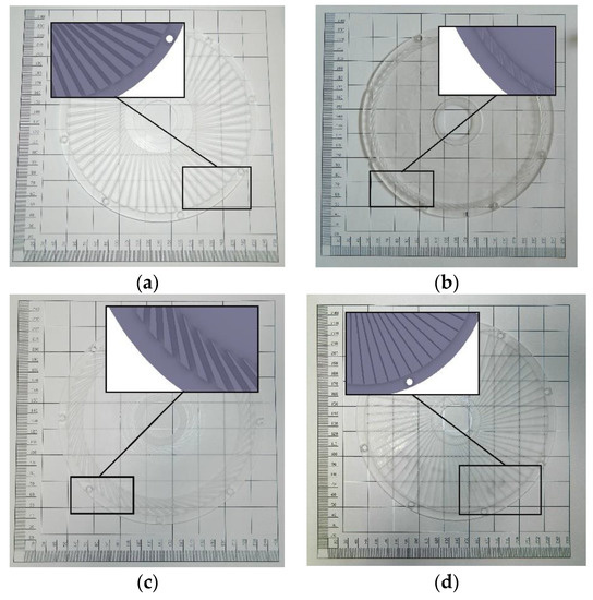
Figure 4.
Passive disc of sets: (a) zk14; (b) zk4; (c) zk13; and (d) zk11.
3. The Test Rig
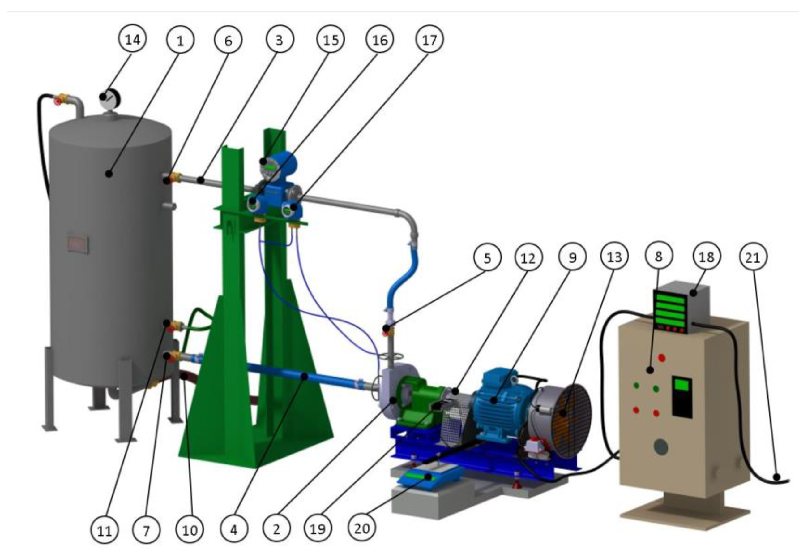
To investigate the performance of the analyzed objects, the pump was mounted in a specially prepared test rig. The scheme of the stand is presented in Figure 5. The pump was located horizontally and was coupled with an asynchronous motor. The squirrel cage motor was fixed to enable swings, which in turn allowed the torque on the shaft to be measured using the scale. The test rig had the possibility to regulate the pump’s operating parameters by alternating the rotational speed. The water was circulating in a closed system, where the inertial pressure was fully regulated.
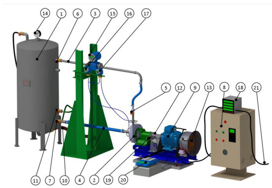
Figure 5.
Scheme of the test rig (3D model) 1—tank, 2—RLP, 3—discharge pipeline, 4—suction pipeline, 5—throttling valve, 6,7—cut-off valves, 8—frequency converter, 9—squirrel-cage motor, 10—drainage, 11—supplying pipeline, 12—coupling cover, 13—fan, 14—manometer/vacuum gauge, 15—electromagnetic flowmeter, 16—absolute pressure meter, 17—differential pressure meter, 18—power meter, 19—electronic tachometer, 20—scale, and 21—power supply.
The overall pressure in the tank and the temperature of the pumped water were measured and controlled during the tests. The curves of the analyzed pump were obtained in accordance with the recommendation given in [36]. The applied measuring devices and their accuracy are presented in Table 3.
Table 3.
Parameters of measuring devices.
According to the details given in [36], the experimental study was conducted in class 1. The hydraulic sets for the investigations were installed in the model pump and proper measurements were conducted. Due to the phenomenon of cavitation occurring for some sets, the rotational speed was lowered to n = 2000 rpm. The results of the measurement were recalculated to a constant rotational speed. Finally, the external curves of each hydraulic set were obtained.
The Model Pump
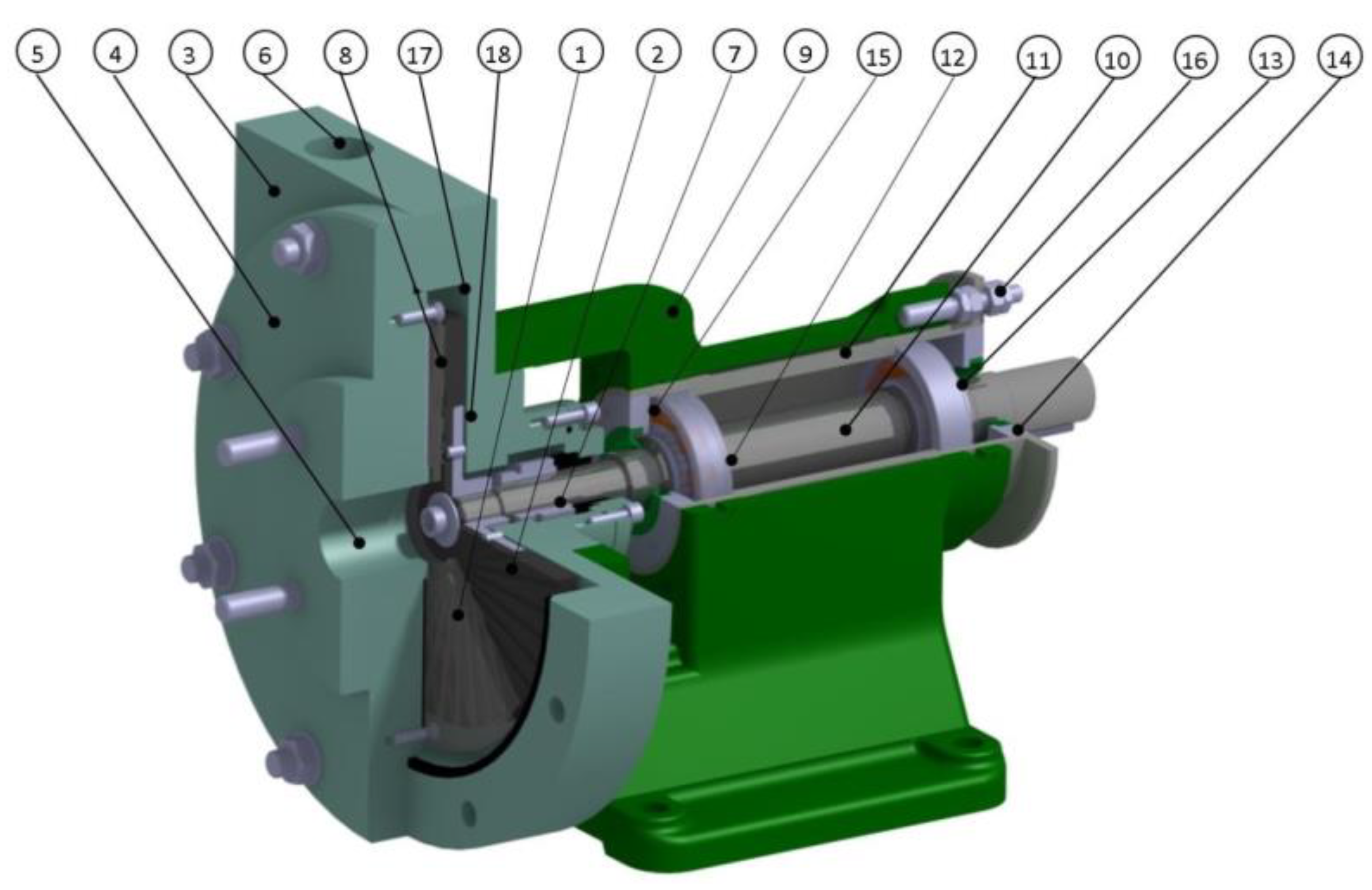
A specially designed radial labyrinth pump was used as the base for the model study of the hydraulic performance of the analyzed geometrical sets. The view of the pump is presented in Figure 6. The pump was designed similarly to a centrifugal unit. The passive and active discs were located vertically in relation to the main axis of the pump. The rotating disc was joined to the shaft of the pump, where the position of the bearing casing (sleeve) could be altered relative to the pump body by means of regulation screws. The applied geometrical solution allowed the clearance between the operating discs to be adjusted and controlled.

Figure 6.
Model pump (3D model): 1—passive disc, 2—active disc, 3—body, 4—pump cover, 5—suction connection, 6—discharge connection, 7—mechanical seal, 8—rubber washer, 9—bearing housing, 10—shaft, 11—regulating sleeve, 12, 13—bearings, 14, 15—sleeve covers with seals, 16—regulating screw, 17—vortex casing, and 18—hub.
The pump was designed to allow it to be easily assembled and dissembled. The alteration of the geometrical parameters of the analyzed pump was obtained by replacing the hydraulic sets. The operating discs cooperated with the vortex casing, the geometrical parameters of which were constant during the course of the tests. As the main sealing of the pump, a mechanical one was used.
4. The Results of Experimental Measurements
The main aim of the conducted research was to find the influence of the geometrical parameters of cooperating discs on hydraulic performance.
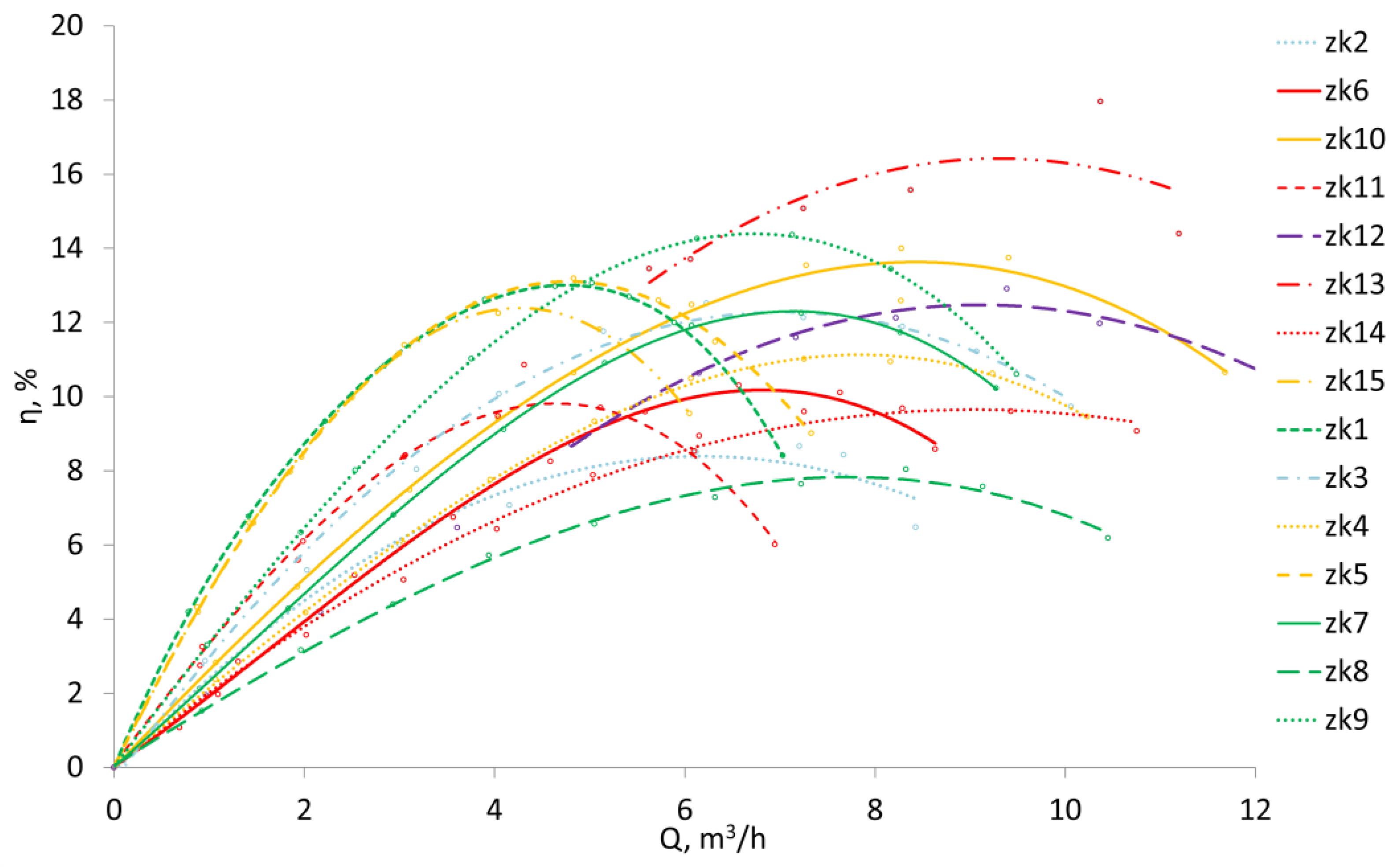
The experimentally obtained curves of flow H = f (Q) (Figure 7), power consumption P = f (Q) (Figure 8), and efficiency η = f (Q) (Figure 9) allow the operation of the RLP equipped with discs with straight grooves to be analyzed. The resultant flow curves are stable for sets zk1, zk3, zk5–zk9, zk11, and zk15, and unstable for zk2, zk4, zk10, zk12, zk13, and zk14. The power consumption curves could be characterized by a different trend, where the following groups can be distinguished:
- curves with an increasing overload character—zk9, zk10, zk12, and zk14;
- curves with a non-overload character:
- with a local maximum for high capacities Q: zk1, zk3, zk4, zk5, zk8, zk11, and zk13;
- with a local maximum for small capacities Q: zk2, zk6, and zk15;
- with a decreasing character in the entire range of Q–zk7.
The flow curve with the highest head was obtained for set zk13, for which the parameters of the best point are: HBEP = 18 m and QBEP = 9.5 m3/h. The efficiency of energy conversion was ηBEP = 16.2%. This set was characterized by the highest efficiency among the tested hydraulic variants. The lowest efficiency was noticed for set zk8, for which at the optimum point QBEP = 8 m3/h, HBEP = 10.8 m, and efficiency was ηBEP = 7.6%.
By analyzing the shape of the curves in the analyses, it is clearly visible that the number of grooves has an influence on the flow curves. When comparing the flow characteristics for sets that differ only in the number of grooves (the other geometric parameters are the same for the pair (Table 2)), i.e., zk1–zk2, zk3–zk4, zk5–zk6, zk7–zk8, and zk9–zk10, higher values of H were obtained with an increase in the number of channels. The only exception is the pair zk3–zk4, for which the increase in the number of channels caused the decrease in parameter H. This situation could be explained by a very small value of inlet diameter d1ap (d1ap = 165 mm for set zk4—Figure 4b), due to which the wetted surface of grooves is very small. This in turn affects the obtained hydraulic parameters. The hydraulic losses in the inlet and outlet cross-section of the discs, which are correlated with quite a short length of channels, determined the external parameters of the pump. The highest rise of the head was obtained for the pair zk9–zk10. This increase, calculated for zk10 in BEP, equals δH = 133%. The smallest increase in the head parameter was achieved for the pair zk1–zk2. In this case, δH = 35% was only obtained for the optimal parameters of set zk2. It should be noted that for Q = 0 m3/h, the obtained head H does not depend on the number of channels for pairs zk5–zk6 and zk7–zk8. In other cases, there was a growth (e.g., for zk1– zk2 o δH = 17.7%), which can be explained by the increase in the momentum exchange.
When comparing the flow curves for the pairs of sets that differ only in terms of the width of the grooves (the other geometric parameters are the same for a pair (Table 2)), i.e.,: zk1–zk3, zk2–zk4, zk5–zk7, zk6–zk8 (height of grooves h= 2 mm), and zk11–zk12 (height of grooves h = 3 mm), it can be concluded that increasing the width s causes the discharge of the pump Q to also grow. The exception here is the pair zk2–zk4, which is due to the reasons described above (value of d1ap for set zk4). The rise of discharge is maximum δQ = 71.4% for the pair zk11–zk12, and minimum δQ = 20.9% for the configuration z6–z8. The difference in the course of the curves H = f(Q) when increasing the groove width s (constant h) is visible as a parallel shift of the curve towards higher values of Q (zk1–zk3 and zk11–zk12). For the remaining cases, there was no clear parallelism between the curves (a similar value of H for Q = 0 m3/h).

Figure 7.
Flow characteristics H = f(Q) of the tested models.
Figure 7.
Flow characteristics H = f(Q) of the tested models.
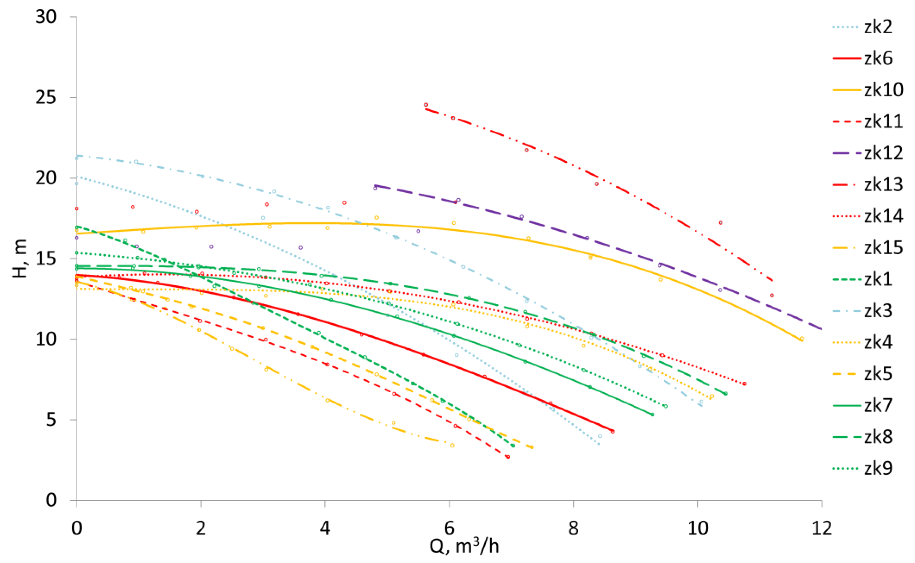
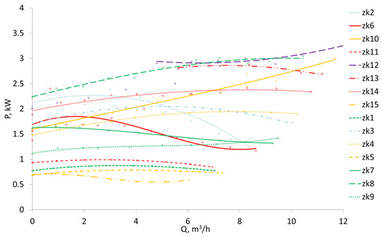
Figure 8.
Power consumption characteristics P = f(Q) of the tested models.
Figure 8.
Power consumption characteristics P = f(Q) of the tested models.

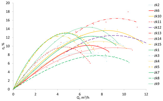
Figure 9.
Efficiency characteristics η = f(Q) of the tested models.
Figure 9.
Efficiency characteristics η = f(Q) of the tested models.
The analysis of the course of the flow curve for set zk15, one of the geometric parameters of which is the depth of the groove equal to h = 1 mm, showed that the lowest value of the discharge was obtained with the head that was comparable to the geometrically similar set zk14. A lack of the implementation of the research plan for the change in this parameter does not allow the impact of its change on the course of the characteristic H = f (Q) to be defined. It should be assumed that its value and the width of the groove in the form of the cross-sectional area of the channel are correlated with the flow inside the pump.
The influence of the inlet angle β1 can be evaluated by comparing the pair of sets zk13 and zk14. As can be seen from the course of the curves, the lowering of the angle leads to an increase in the size of the head. In the analyzed case, for Q = 5.8 m3/h (the break point of the flow curve for zk13), there was an increase in the head H of δH = 100% when compared to zk14. For sets zk1–zk8 (except for set zk4), the decrease in the angle from β1 = 50° to β1 = 30° also leads to the increase in parameter H.
The external parameter that relates to the analyzed variables, in accordance to Equation (4), is the inlet diameter d1ap. As was shown in previous studies, the flow curve H = f (Q), characterized by the highest values of the head, was obtained for the largest inlet diameters d1ap = 146 mm − zk13, and also for set zk12 − d1ap = 140 mm and zk3 − d1ap = 115 mm (except set zk4). Since Q = 0 m3/h, the conducted tests showed that the number of grooves for some of the analyzed sets affects the head H0, whereas for other sets, it does not. It can be assumed that apart from the analyzed parameters z, s, β1, and k, the value of the inlet diameter d1ap has a significant influence on the hydraulic parameters achieved by the pump. Therefore, for further analysis, this parameter should be analyzed as an independent variable, which would enable the impact on the analyzed variables to be determined.
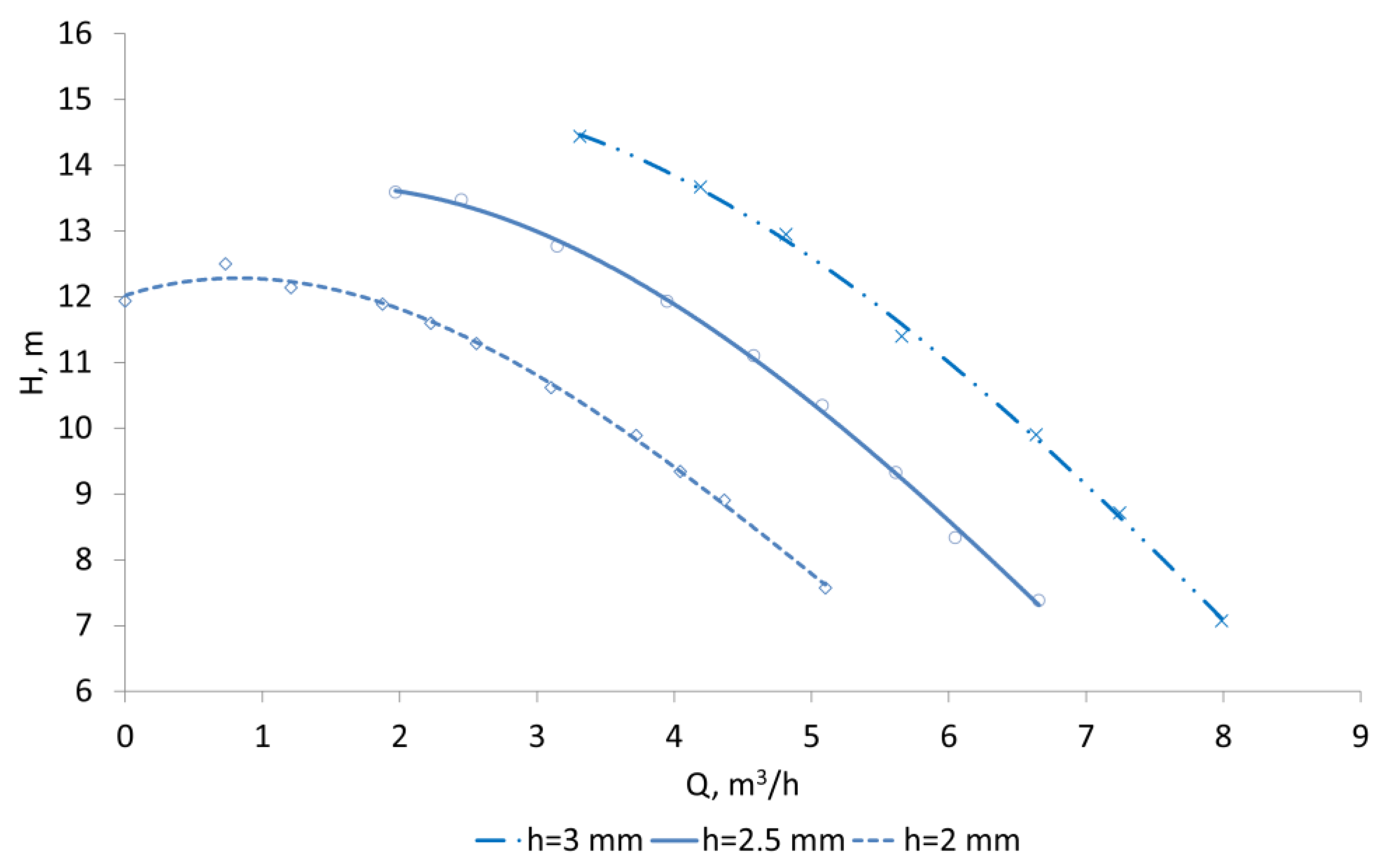
In the experimental planning, in order to limit the number of trials, the impact of the depth of the grooves on the course of the pump’s performance was not fully taken into account. In order to identify this impact, appropriate tests for set zk13 were carried out. The flow geometry of the analyzed set was modified by cutting facing surfaces of the active and passive discs. As a result, the depth of channels was reduced to the range h ∈ {2; 2.5; 3}. As a consequence of the conducted measurements, the curves H = f (Q) were obtained, which are shown in Figure 10. The tests were performed at a speed of n = 1500 rpm. Due to the instability of characteristics, only the stable part is shown on the graph.
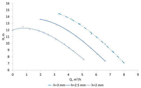
Figure 10.
The influence of the height of the groove on the flow curve (H = f(Q), set zk13, n = 1500 rpm).
The results of the conducted research show that the increase in parameter h caused the rise of the flow. The alteration of the flow chart could be noticed by a parallel shift towards a higher discharge. It is caused by the increase in the flow cross-section through the pump in relation to the base model (h = 3 mm), with δA = 18.7% for h = 2.5 mm, and δA = 37.3% for h = 2 mm. It is important to notice that for the height h = 2 mm, the obtained curve was quasi-stable. When extrapolating the flow curve H = f(Q) and determining the position of the point H0 for Q = 0 m3/h, it could be assumed that the change in height of the channel also influences the pump’s head, which can be explained by the intensification of the liquid circulation process.
5. The Analysis of the Performance of the Selected Hydraulic Sets
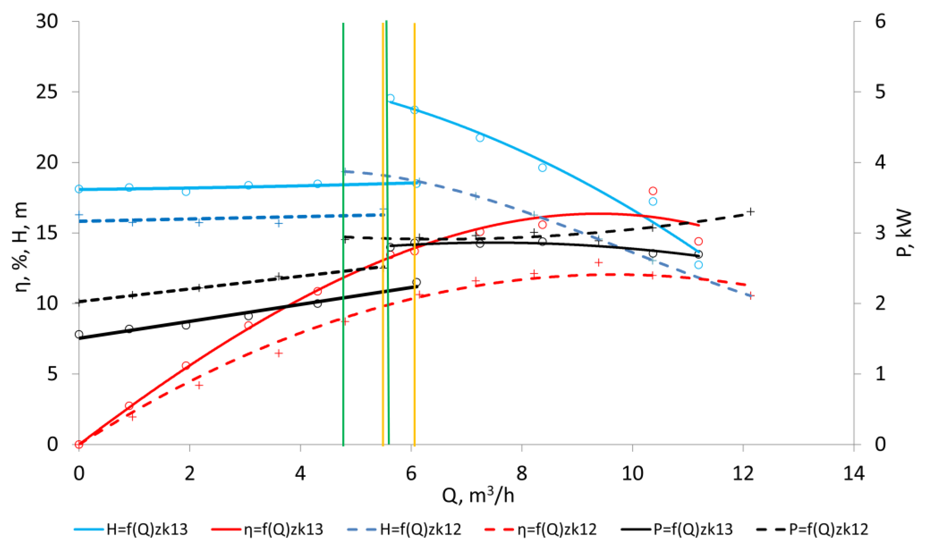
The conducted experimental studies showed that the highest value of the head was gained for sets zk12 and zk13, and therefore their operation (Figure 11) was subject to a detailed analysis.
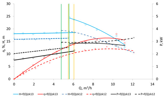
Figure 11.
The comparison of the characteristic curves for sets zk12 and zk13, n = 2000 rpm.
The results of the investigation for sets zk12 and zk13 are characterized by the unstable form of the flow characteristic. While decreasing the value of the discharge in the pump, a sudden drop in the head was observed for Q ≈ 4.8 m3/h − zk12 and Q ≈ 5.8 m3/h − zk13 (green continuous lines in Figure 11). In the course of opening the regulating valve, this point was shifting towards a higher flow, in turn resulting in a hysteresis for the determined curve (green dashed lines in Figure 11). The hysteresis was also noticed for the power consumption curve. The occurrence of the sudden drop in the head can be explained by the presence of swirls in the working elements of the pump [37].
For set zk12, the maximum head was Hmax = 19.4 m and the maximum head coefficient was ψmax = 1.07. The optimum point parameters were: QBEP = 9.4 m3/h, efficiency ηBEP = 12%, and head coefficient ψBEP = 0.8. The specific speed of this set was nqBEP = 13.7.
In the case of set zk13, the maximum head was Hmax = 24.5 m for the flow Q = 5.8 m3/h. At this point, the pump was characterized by the head coefficient equal to ψmax = 1.36 and specific speed nq ≈ 7. The tested set of discs achieved a maximum efficiency of ηBEP = 16.2% for the capacity QBEP = 9.5 m3/h and head HBEP = 18 m, which in turn defines the value of the specific speed in the BEP of nqBEP = 11.8.
The analyzed sets zk12 and zk13 are characterized by large ratios d1ap/d2tap for zk12 d1ap/d2ap = 0.78 and for zk13 d1ap/d2tap = 0.81, respectively.
In the case of an increase in the inlet diameter d1ap (and with the assumption that the number of channels is large enough to fill the entire inlet sections of both disks), the hills between the grooves become similar to the vanes. The blades obtained in this way are widened. The increase in the inlet diameter d1ap value leads to the reduction in the coefficient of the constriction at the outlet φ2 and to the increase in the head. Therefore, it is better to use discs equipped with blades than to use grooved discs.
6. The Comparison of the Cooperation between a Smooth Disc and a Passive Disc
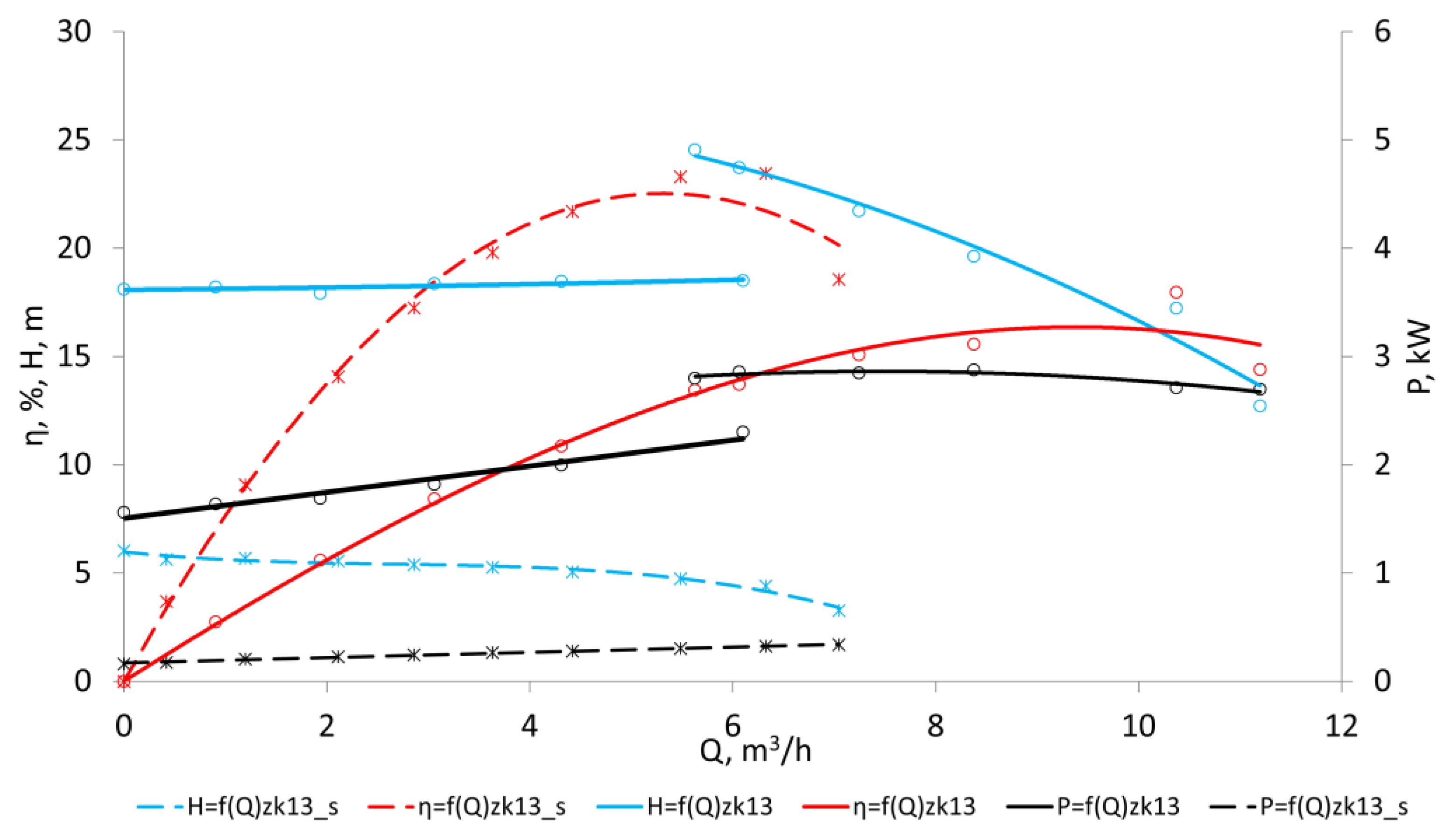
The main aim of the application of the passive disk is to initiate and keep a momentum exchange process between two working elements. Such a solution meets the requirements of axial pumps, as was mentioned in [12,13,17]. In order to define the influence of the application of the grooved passive disc on the hydraulic performance, appropriate tests were carried out where the active discs of sets zk13 and zk14 were put together with a smooth passive disc. The tests were conducted for different rotational speeds, which for set zk14 was equal to n = 2920 rpm, and for set zk13 it was reduced to the value of 2000 rpm due to the occurrence of cavitation. The results of the measurements are shown in Figure 12 and Figure 13.
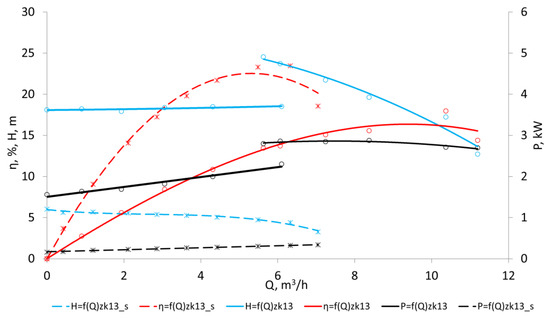
Figure 12.
The comparison of the characteristics of the mutual cooperation between the active disc from set zk13 and the grooved and smooth passive discs (n = 2000 rpm).
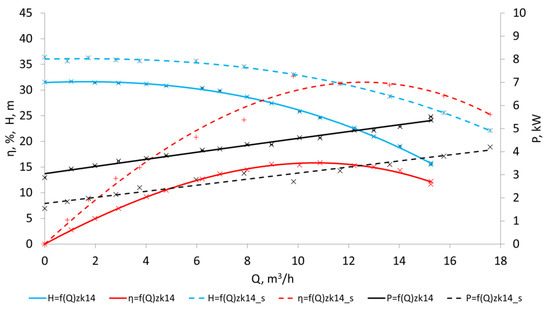
Figure 13.
The comparison of the characteristics of the cooperation between the active disc from set zk14 and the grooved and smooth passive discs (n = 2920 rpm).
For the set consisting of the active disc zk13, which was cooperating with the smooth passive disc, a lower value of the head was obtained with regards to the base model for the whole capacity range (Figure 12). The obtained head decreased almost 1.8 times for Q = 0 m3/h and 2.7 times for Q = 5.8 m3/h (the point with the maximum parameter H for the set with the grooved passive disc). In the case of the elimination of the flow instability, higher values of differences in the head for the lower range of the flow should be expected. A reduction in the hydraulic parameters of the pump leads to a decrease in power consumption and an increase in efficiency of approximately Δη ≈ 5%. The optimal point moved towards lower capacities by ΔQ ≈ 3 m3/h. The application of the grooved passive disc for set zk13 leads to the increase in size of the generated head, which can be seen to be beneficial.
From the analysis of the course of the characteristic curves (Figure 13) for the active disc from set zk14, it can be concluded that the application of the passive grooved disk leads to the decrease in the height H when compared to the model with a smooth motionless face. This difference is equal to a maximum ΔH ≈ 11 m (68.7%) for Q = 15 m3/h. The efficiency of the conversion of mechanical energy into hydraulic energy is higher in the case of the smooth disk and equals ηBEP = 31%, while for the grooved disk, it is about half the amount (ηBEP = 16%). The best point, due to the reduction in the steepness of the flow and power consumption characteristics, was shifted towards the higher flow. To sum up the carried out investigations, for the application of the channel passive disc for set zk14 in the process of energy conversion, the centrifugal effect of the active disc is significant, as opposed to set zk13, which does not lead to an increase in the height H, and thus the analyzed geometric solution does not meet the required assumptions.
However, as was demonstrated by comparative studies of the collaboration of the smooth and grooved passive disc with the rotating active one, for some geometric solutions, it is advantageous to apply a channel passive disc in order to obtain a lower value of specific speed. When examining the geometrical parameters of both sets, it can be concluded that the geometry with spreading vanes and a low value of the coefficient of the constriction at the outlet φ2 (zk13) ensures (apart from centrifugal action) the exchange of momentum. This is opposite to the case of set zk14, for which the value of φ2 is much larger.
7. Summary
The article presents an experimental study of the radial labyrinth pump (RLP). The conducted study should be treated as a preliminary investigation, where the main goal was to recognize the possibility of increasing the hydraulic energy transferred to fluid by means of opposite grooved discs. This approach, based on the analysis of hydraulic characteristics, provided a lot of information that is significant from an engineering and research standpoint. Labyrinth pumps are not common units; however, in some applications their use could be justified, especially in cases when the pumping performance should be correlated with the possibility of mixing components. Therefore, the conducted investigations are valuable with regards to operation and reliability.
The experimental investigations of the prototype research unit were conducted in order to identify the hydraulic parameters achieved in the RLP. The measurements were carried out for 15 different sets of hydraulic solutions. The scope of the research took into consideration different inlet angles, heights of the channel, widths of the channel, and the number of channels, as well as indirectly the alteration of ratio d1ap/d2ap. Other geometric parameters, i.e., outer diameter, dimensions of the volute, and the gap between discs, were unchangeable. In accordance with the conducted analyses and the presented results of the investigation, other conclusions can also be drawn:
- The highest efficiency of the energy conversion from mechanical into hydraulic was obtained for set zk13 and it was equal to ηBEP = 16.2% for QBEP = 9.5 m3/h and the specific speed value nq = 11.8.
- The measurements of the cooperation between the active grooved disc and the smooth passive disc showed that the use of the grooved passive disc leads to the increase in the achieved height H. However, this is not the case for each active disc.
- For sets with the grooved passive disc, the reduction in the constriction coefficient at the outlet φ2 causes the increase in the height H (assuming the maximum possible number of channels). This is related to the increase in the ratio d1ap/d2ap (up to the maximum value for set zk4, which was characterized by the highest ratio d1ap/d2ap, and an increase in the height H was not noticed). Therefore, from an energy point of view, it is more advantageous to use blade discs than channel discs.
- The value of diameter d1ap affects the obtained hydraulic parameters, and therefore it is necessary in further research that this variable is independent from the number of grooves.
The limitations of the hydraulic system taken into consideration should be considered according to the range of parameters shown in Table 1 and Table 2, and should be similar for pumps with a similar specific speed. Further work on the RLP’s construction should be aimed at detailing the research plan for the geometric parameters of the zk12 and zk13 sets. Additionally, the cause of the appearance of instability on the H = f(Q) curve, related probably to the process of cavitation, should be clarified, which is a separate research issue.
Author Contributions
Conceptualization, P.S.; methodology, J.S.; software, W.L.; formal analysis, P.S.; investigation, J.S.; resources, W.L.; data curation, P.S.; writing—original draft, P.S.; writing—review and editing, J.S. and W.L. All authors have read and agreed to the published version of the manuscript.
Funding
This research received no external funding.
Data Availability Statement
The data presented in this study are available on request from the corresponding author.
Conflicts of Interest
The authors declare no conflict of interest.
Nomenclature
| d | Diameter, (mm) |
| d1ap | Inlet diameter of active/passive disc, (mm) |
| d2ap | Outlet diameter of active/passive disc, (mm) |
| F | Force (N) |
| G | Gravitational acceleration, (m/s2) |
| h | Height (mm) |
| H | Pump total head (m) |
| K | Head coefficient (for labyrinth pump) |
| n | Rotational speed (rpm) |
| nq | Kinematic specific speed (nq = nQ0.5/H0.75) (rpm) |
| p | Pressure (Pa) |
| P | Power consumption (W) |
| s | Width (mm) |
| T | Temperature (°C) |
| Q | Flow rate (m3/s) |
| Y | Specific energy (J/kg) |
| z | Number of grooves |
| β | Groove angle (°) |
| δ | Clearance (mm) |
| ν | Viscosity (m2/s) |
| η | Total efficiency |
| ρ | Density (kg/m3) |
| ψ | Head coefficient (universal) |
| φ | Coefficient of contraction (universal) |
References
- Satoh, H.; Uchida, K.; Cao, Y. Designing an Ultra-Low Specific Speed Centrifugal Pump. Turbomachinery 2005, 33, 316–322. [Google Scholar]
- Adler, D. Low Specific Speed Impeller. Patent 96/08655, 1996. [Google Scholar]
- Koji, K. Low Specific Speed Impeller. Patent 7208392 A, 1994. [Google Scholar]
- Koji, K. Low Specific Speed Impeller. Patent 9209983 A, 1997. [Google Scholar]
- Hergt, P.; Nivklas, A.; Scianna, S. Centrifugal Pump Impeller With Low Specific Speed. Patent 90/07650, 1990. [Google Scholar]
- Gulich, J. Centrifugal Pumps; Springer: Berlin, Germany, 2020. [Google Scholar]
- Jedral, W. Rotodynamic Pumps; PWN: Warsaw, Poland, 2011. [Google Scholar]
- Meng, Y.; Li, C.; Yan, H.; Liu, X. Numerical simulation of the ultra-high-speed lowspecific-speed rotodynamic pump and application research in hydraulic system. In Proceedings of the IPCSIT, Singapore, 16–18 September 2011; Volume 2, pp. 179–183. [Google Scholar]
- Kurokawa, J.; Yamada, T.; Hiraga, H. Performance of low specific speed pumps. In Proceedings of the 11th Australasian Fluid Mechanics Conference, Hobart, Australia, 14–18 December 1992; pp. 861–864. [Google Scholar]
- Skrzypacz, J. Investigating the impact of multi-piped impellers design on the efficiency of rotodynamic pumps operating at ultra-low specific speed. Chem. Eng. Process. 2014, 86, 145–152. [Google Scholar] [CrossRef]
- Golubiev, A.I. Labirynth Pump. Patent USSR 602029/25, 1960. [Google Scholar]
- Golubev, A.I. Labitynth Pumps for Chemical Purposes; Mashgiz: Moscow, Russia, 1961. [Google Scholar]
- Golubev, A.I. Labitynth-Threaded Pumps and Sealings for Aggressive Fluids; Mashynostroyene: Moscow, Russia, 1981. [Google Scholar]
- Golubev, A.I.; Pyatigorskaya, E.I. Efficiency coefficients of a labyrinth pump. Chem. Pet. Eng. 2005, 41, 260–266. [Google Scholar] [CrossRef]
- Grabow, G. Vergleichsbetrachtungen zu Seitenkanal-, Labyrinth- und Strahlpumpen. Forsch. Im Ingenieurwesen–Eng. Res. 1994, 62, 11–20. [Google Scholar] [CrossRef]
- Golubev, A.I.; Pyatigorskaya, E.I. Determination of optimal parameters of labyrinth-screw seals and pump. In Proceedings of the 16th International Conference on Fluid Sealing, Brugge, Belgium, 18–20 September 2000. [Google Scholar]
- Golubev, A.I.; Pyatigorskaya, E.I. Optimization of the hydraulic calculation for labyrinth-screw seals and pumps. In Proceedings of the Ninth International Scientific-Technical Conference Hervicon-99, Sumy, Ukraine, 7–10 September 1999; Available online: https://hervicon.sumdu.edu.ua/uk/history/hervicon-1999 (accessed on 5 June 2023).
- Guo, Y. Numerical and Experimental Simulation of the Trapezii Form Labyrinth Screw Pump. Ph.D. Thesis, Beijing University of Chemical Technology, Beijing, China, 2005. [Google Scholar]
- Guo, Y.; Zhang, Y.; Li, J. Numerical simulation of the interial flow in a complex trapeziform labyrinth screw pump. J. Beijing Univ. Chem. Technol. 2008, 35, 44–49. [Google Scholar]
- Ma, R. CFD Numerical Simulation and Experimental Study of the Pumping Mechanism and Pumping Performance of Labyrinth Screw Pump. Ph.D. Thesis, Beijing University of Chemical Technology, Beijing, China, 2009. [Google Scholar]
- Ma, R.; Wang, K. CFD Numerical simulation and experimental study of effects of screw-sleeve fitting clearance upon triangular thread labyrinth screw pump. J. Appl. Fluid Mech. 2010, 3, 75–81. [Google Scholar] [CrossRef]
- Ma, R.; Wang, K. Modelling of pumping performance of labyrinth screw pump (LSP) by 2d Reynolds stress equation. J. Fluid Eng. 2009, 131, 085001. [Google Scholar] [CrossRef]
- Ma, R.; Wang, K.; Li, J. Study on pumping mechanism of labyrinth screw pump by numerical simulation of computational fluid dynamic (CFD) and pump performance experiment. Lubr. Eng. 2008, 24, 75–79. [Google Scholar]
- Wang, C.; Zhang, H.; Peng, N.; Zhao, B.; Zheng, H. Numerical calculation and experimental study for interior flow field in triangular labyrinth screw pump. J. Drain. Irrig. Mach. Eng. 2009, 27, 73–77. [Google Scholar]
- Zahng, Y.; Yang, C.; Li, J. Numerical simulation and experiment of gas-liquid two-phase flow field in labyrinth screw pump. J. Drain. Irrig. Mach. Eng. 2010, 28, 492–496. [Google Scholar]
- Vasilcov, E.A.; Nevelic, V.V. Hermetic Elektopumps; Mashynostroenye: Leningrad, Russia, 1968. [Google Scholar]
- Andrenk, P.; Lebedev, A. Labyrinth screw pump theory. Motrol. Comm. Mot. Energetics Agric. 2014, 16, 35–42. [Google Scholar]
- Zhang, S.; Zhang, Y.C.; Yan, H.; Yang, W.M. Numerical simulation and experimental study of gas-liquid two-phase flow of series-connected combined labyrinth screw pump. Ind. Saf. Environ. Prot. 2016, 42, 14–17. [Google Scholar]
- Li, J.J.; Zhang, Y.C. Numerical simulation of series combined labyrinth screw pump based on Fluent. J. Drain. Irrig. Mach. Eng. 2014, 32, 296–301. [Google Scholar]
- Ma, Q.Y.; Zhang, Q.Z.; Zhang, L.F.; Silan, F. Numerical simulation and experimental research on the internal flow field of rectangular labyrinth pump. Fluid Mach. 2017, 45, 1–4. [Google Scholar]
- Wang, C.; Zhang, Y.C.; Li, J.Z. CFD simulation of maze screw pump coal water slurry transportation and preliminary discussion of internal wear. Guangdong Chem. Ind. 2011, 38, 57–59. [Google Scholar]
- Rong, X.; Zhu, H.; Hu, B. Performance Research and Structure Optimization of Labyrinth Screw Pump. Micromachines 2021, 12, 790. [Google Scholar] [CrossRef] [PubMed]
- Li, T.T. Theoretical Design, CFD Numerical Calculation and Experimental Study on Rectangle Labyrinth Screw Pump; Jiangsu University: Zhenjiang, China, 2007. [Google Scholar]
- Jia, F. Large Eddy Simulation and Experimental Study on Trapezium Labyrinth Screw Pump; Jiangsu University: Zhenjiang, China, 2013. [Google Scholar]
- Lazarkiewicz, S.; Troskolanski, A. Impeller Pumps; Pergamon Press: Warsaw, Poland, 1965. [Google Scholar]
- EN ISO 9906:2012; Rotodynamic Pumps—Hydraulic Performance Acceptance Tests—Grades 1, 2 and 3. The European Standard: Brussels, Belgium, 2012.
- Plutecki, W.; Szulc, P.; Plutecki, J. The influence of the vane diffuser head losses curve on the external characteristic of high specific speed pumps. J. Pet. Sci. Eng. 2018, 162, 394–406. [Google Scholar] [CrossRef]


Disclaimer/Publisher’s Note: The statements, opinions and data contained in all publications are solely those of the individual author(s) and contributor(s) and not of MDPI and/or the editor(s). MDPI and/or the editor(s) disclaim responsibility for any injury to people or property resulting from any ideas, methods, instructions or products referred to in the content. |
© 2023 by the authors. Licensee MDPI, Basel, Switzerland. This article is an open access article distributed under the terms and conditions of the Creative Commons Attribution (CC BY) license (https://creativecommons.org/licenses/by/4.0/).