1. Introduction
Crushing and grinding have different techniques for the process of size reduction. While the crushing operation for size reduction is carried out by compression, impact and attrition have less impact. In the case of grinding, the attrition force is much more impactful and great. Both dry and wet conditions can be used to operate the grinding mill. The grinding media used for grinding purposes are most commonly spherical or cylindrical balls, causing a crushing action by striking the ore continuously, resulting in a size reduction. One end of the mill receives the material, while the other end removes the discharge. The size reduction strategy is heavily influenced by the amount of energy required for size reduction as well as the choice of crusher or grinder. In contrast, the amount of energy needed is determined by the rock’s starting size and hardness and the eventual product that must be produced.
In the past, the mineral processing industry found fine grinding undesirable due to disadvantages related to conventional milling (through tumbling mills). The only way to obtain the necessary grinds for the tougher minerals was to mill them for a lengthy time, which resulted in limited productivity and higher power usage [
1]. Smaller media in closed circuits can help tumble mills produce fine grinds, but their ability to transmit kinetic energy to the media is still fundamentally limited. They also have significant areas where minimal media movement occurs (dead grinding zone), which reduces efficiency. Ultrafine grinding (UFG) mills overcome these constraints by utilising revolving stirrers inside a steel mill shell. Recently, new-generation mills have been gaining popularity in the finer comminution circuit for reducing specific energy consumption. The autogenous/semi-autogenous mills were also used along with a ball mill for intermediate-size grinding. However, there is a new configuration of the grinding circuit composed of a high-pressure grinding roll and stirred media mills as a fine and ultrafine grinding unit, respectively, which is a recent trend. Stirred mills are compressive grinding mills with potential in the mineral- and cement-based processing industries for reducing the particle size from a few millimetres to a micron.
Each ore has a preferred particle size for economic reasons; too fine a grind and grinding expenses surpass any increase in recovery, whereas too coarse a grind and inadequate liberation restrict recovery in the separation stage. The amount to which the values are disseminated in the gangue and the subsequent separation method to be utilised will both affect the ideal grind size in liberating the grain, and the energy consumption is one of the main factors in grinding materials.
There is also an effort to achieve net zero, and in that, energy transition is a key factor. As grinding is one of the energy-consuming processes in the mining and mineral processing value chain, any effort towards reducing energy is a positive step. So, by adopting an advanced energy-efficient comminution circuit, there is a benefit towards minimising CO2 emissions.
There are several published pieces of literature focusing on the grinding of minerals and materials. However, very few articles have been published on ultrafine grinding using stirred media mills, one of the recently adopted technologies by mining industries. Also, there is a lack of a systematic knowledge base on this important research topic. So, a review article in this direction will be useful for the researchers, technocrats, as well as plant operators as a reference resource.
The present literature review focuses on investigating the energy-efficient ultrafine grinding of particles using stirred mills. To that end, it will give a general overview of various size reduction techniques, with an emphasis on energy consumption in different mills. Further, factors affecting particle size distribution and assessing the potential of stirred milling will be discussed. The review aims to emphasise the benefits of stirred mills over conventional tumbling mills. Also, to further understand the effect of grinding media on the product size and energy consumption, this review aims to attain knowledge of stirred mill-based energy-efficient mills regarding ultrafine grinding techniques and the implications of those techniques for industrial applications.
2. Grinding
Grinding is one of the key steps in the comminution process in different industries, including mining, mineral processing, cement, etc. It is generally used in the process flow sheet to liberate, separate, and micronise processes in mineral processing. The main objective of the isolation of fine materials from the mixed material that follows is to achieve adequate sizing for further processing through classification or separation technologies. In general, the material is ground to achieve a particle size below 1 mm to sub-micron sizes based on the requirement.
Several grinding “stages” can be adopted in the size reduction process depending on the size of the target product. It is believed that regrinding creates particles with a fineness of less than 75 µm and as little as 30 µm. Fine grinding, which occurs at 30 µm below particles, broken down to about a lesser size of 10 µm, is a more recent development. As the particle size is less than 10 µm, the “extremely fine grinding” phase might be used. The use of energy and steel components like media, liners, etc. significantly influences the cost of grinding. In the process of processing minerals, grinding uses the greatest energy. Metalliferous ore grinding is frequently the most energy-intensive collection of activities and accounts for around a quarter of the 2% of the world’s energy that is used for mineral comminution [
2,
3]. Ultrafine grinding is the procedure in which the size of the particles is in the vicinity of nanometres when matched with various other synthesis techniques. With quicker production levels (tonnages of nanomaterials can be generated in an hour), mechanical attrition techniques are frequently utilised in manufacturing industrial materials, including metal, clay, and coal powders [
4].
The demand for mining materials, cement, and comminution operations is always necessary for the process flowsheet. The material needs to be processed into finer-sized products, which causes energy consumption to be higher [
5]. The industrial process of ultrafine grinding uses 4% of the whole world’s electrical power and amounts to almost 50% of the entire consumption at the mine site [
6]. This is the reason why an energy-efficient method needs to be developed. The selection of a grinding mill depends on the size reduction limits to be achieved in grading results. So, the process always aims to minimise the energy used.
2.1. Size Reduction in Comminution
Before separating minerals from the gangue, particles have to be broken down by comminution through crushing and grinding. The objective of this process is for the particle size of the ore to be broken down until one can obtain fine or liberate quality minerals from the gangue. With comminution, it can achieve minerals of the desired size, making it easier for the conveyors or ore carriers to handle the after-product. The particle’s surface area is increased using the size reduction method. The amount of mass and heat transmission and chemical reactions are typically clearly proportional to the unit operation’s area and the solid particle’s chemical reactions. This technique is carried out because an increased surface area makes such activities easier.
As a result, the rate of solid particle combustion is approximately equal to the area subjected to the gas, though several residual factors may also be involved. Sometimes, these sizes of the particle influence the material property, and, hence, it is reduced. This technique for particle size reduction is easy to understand; the materials break into large, intermediate, and fine-sized particles with the sudden impact subjected to the mass of the material. When energy increases, the larger particles will be widespread and smaller. However, there is a marginal change in the product size while grinding a finer particle size range. The internal structure of the material is associated with the size of fine particles. The reduction process of the material size is correlated with larger particle sizes [
7].
2.1.1. Crushing
Grinding becomes simpler after the ore has been crushed until the minerals and gangue have been largely separated. After this activity, the ore is compressed by pushing the material against a surface in a tightly contained motion. One of the stages in the crushing process is the reduction ratio. The feed-to-product size ratio is the ratio of the largest particle entering the crusher to the largest particle leaving it. Feed is generally subjected to multiple crushing stages to reduce the particle size and enable it to feed into the grinding process.
2.1.2. Grinding
The impact, attrition, and abrasion of the feed material help in attaining the grinding of ore. Grinding is accomplished both through the slurry and in the dry mode. Grinding with the help of a mill can take down a few steps of crushing. Tumbling mills need just half of the cost and energy for grinding as those of crushing [
8]. The only drawback is having a more complex circuit with high maintenance [
9,
10,
11]. However, advanced mills such as stirred media mills are more energy-efficient for P
80 = 50 µm. This is because stirred mills emphasise more shear energy than impact energy and have greater power intensity than ball mills.
2.2. Fine Grinding
Comminuting and synthetic are the two methods for producing ultrafine particles [
12], carried out either by the mechanical process or chemical reaction. The synthetic process produces particles in a smaller size with a high purity but low output and narrow particle distribution, making the production cost higher and involving a complicated production technology. In the comminuting method, the output is high, but the production cost is considerably lower due to the simpler production technology. This is why the comminuting method is preferred. The schematic diagram of these mechanisms is shown in
Figure 1.
Certain criteria must be met to use the comminuting method. Riding aids must be used. Furthermore, the grinding equipment must generate intensely concentrated energy that has a violent attraction and impaction on the particle [
12]. So as not to form large particles from the ground particles, the grinding aids must be closely observed when the acting force becomes vigorous. Because of the grinding assistance, the material’s surface area and dispersivity rise, reducing the particle size. This demonstrates the grinding aid value in creating ultrafine particles. Compression, impact, shear, and attrition are the four mechanisms that contribute to reductions in particle size. The type of grinding machine required depends on parameters such as the feed size (F
80), product size (P
80), ore hardness, ore type, equipment availability, operating costs, maintenance costs, etc. [
13,
14].
Figure 1.
Mechanism of grinding in a tumbling mill (white shapes—grinding media, black shapes—particles, and arrow marks—forces acting on a particle) [
15].
Figure 1.
Mechanism of grinding in a tumbling mill (white shapes—grinding media, black shapes—particles, and arrow marks—forces acting on a particle) [
15].
2.3. Evolution of Ultrafine Grinding
The higher cost of the energy usage in grinding, steel media cost, grinding media wear rate, and mill’s complex design cause an increase in the capital cost, the reason for the high cost of the grinding material [
16]. To overcome these factors, researchers have found ways to decrease energy consumption by either finding a substitute for steel media with a more conventional type or changing the grinding chamber’s configuration. Here, we are focusing on the latter. Just by optimising the operating parameters like the type and grinding media size, rotation speed, and grinding process, it can be seen that there was a change in the size range of the ultrafine product and the energy requirement; it was possible to cover 10–2000 kW/t of dry solids compared to before. There was a change in the coarseness of the end-product and a decrease in the product size. These developments were achieved by changes in the agitator and media separator design, the size of the mill, and the distinct method for separating liquid and feeding solids in the stirred ball mill [
17].
Ultrafine grinding using a stirred mill was first introduced by Klein & Szegvari when they performed a wet grinding test for the first time in 1928. They used an agitator and spherical grinding media [
17]. After this, many industries such as the cement, metallurgical, pharmaceutical, cosmetic, material, chemical, and biomass power industries followed the same concept [
18,
19,
20]. Many developments were made in terms of grinding media material, energy efficiency, design parameters, applications, and operating conditions. The high energy usage in the grinding process causes the need for an energy-efficient system. The ultrafine material requirement was already an energy-intensive process compared to coarse grinding.
Figure 2 represents the correlation between the specific energy (kWh/t) and product size (µm). Variations in circuit configuration, ore hardness, and operating parameters and conditions all contribute to the variation in specific energy consumption [
21].
Controlling the particle size distribution closely allows you to reduce the error margin when producing critical materials. The maintenance on these machines is much lower than one might expect because producing the results requires only a small amount of force. In general, only the motor bearings and support springs require maintenance, which means that these mills not only save money but also reduce equipment downtime, increasing productivity.
Figure 3 depicts the range of application and the level of size reduction of the principal grinding methods used in mineral ore processing, reducing the particle size from 500 mm to sub-15 µm through ultrafine grinding [
23].
2.4. Application of Ultrafine Grinding
Everything that has increased our standard of living is because of the extraction of metals from minerals that are used for various purposes. And for the mineral to be useful, various technological advancements are being made. Ultrafine grinding using stirred mills has been quite popular after its introduction in 1928, making grinding minerals for valuable metal extraction easy and affordable.
The objectives of the grinding process are to bring down the size of the particle, increase the surface area, or liberate the particles. Before this, blasting and the primary and secondary crushing of material are used to break down minerals. Extended milling could achieve the hard mineral’s desired grind, making it an energy-intensive process. The energy transfer between the particles reduces with the decrease in the impartation of kinetic energy to the particle using finer media. Ultrafine grinding mills were developed to get around these restrictions. Ultra-fine grinding mills were once utilised in numerous commonplace industries, including manufacturing medications, dyes, clays, paint, and pigments. In the mineral sector, these mills have largely been used to liberate particles of gold ores, magnetite ores, copper–lead–zinc deposits, and platinum ores with liberation sizes of 15 µm or less [
24].
3. Milling Technology
Before the introduction of third-generation grinding mills for wet fine and ultrafine grinding, tumbling mills were used. The number of revolutions controls the power consumption for the grinding of media. Hence, it has a moderately smaller power density. However, for ultrafine grinding, the time required for grinding is considerably longer. The traditional grinding machine, a tumbling mill consisting of grinding media such as steel rods (in the case of a rod mill), balls (in the case of a ball mill), or rock (in the case of the autogenous mill), had the working phenomenon of a rotating shell, and the motion imparted was charged by the mill shell. The type of motion, the distance between each medium piece, the amount, and the particle size are some variables that affect grinding in the tumbling mill. The possibility of an ore particle entering a zone between medium units (balls, rod, etc.) and the likelihood that a breakage event will occur after entry define the degree of grinding. Generally, a feed 20 mm in size is regarded as fine grinding, and 150 mm is considered coarse grinding. Similarly, tumbling mills reduce particle sizes between 5 and 250 mm, and 25 and 300 µm [
25].
The tumbling mills were used for the purpose of conventional grinding. The motor where the ore is ignited rotates the horizontal mill’s cylindrical body. The grinding medium then started tossing as a result. Impact, attrition, and abrasion are created during grinding because of the free movement of unconnected media like ceramic balls, coarse ore pebbles, or steel rods. Ball mills work well for finer grinding, whereas rod mills can handle coarse grinding. Both of them use a grinding medium in the form of rods or balls and rotate the shell. In most cases in mineral processing applications, the grounded particles flow in the form of a slurry to the concentration process. So, wet grinding is favoured compared to dry grinding. However, dry grinding has several uses [
25,
26], such as cement, pharmaceutical, etc. The energy needed for slurry feed reduces the process of comminution, which can further be reduced by adding chemicals that get absorbed into the solid [
27]. The surface energy lowers because the absorptions provided to the surfactant rupture as the bond strength decreases. Ball mills have a lesser power intensity than, i.e., the power per unit volume of the mill compared to that of the stirred mill, which makes it less compatible [
28]. Also, the energy needed for processing is much higher for obtaining the desired product size. The iron media used for grinding were contaminated, making it hard to achieve the desired flotation performance.
Selection of Mill Types
A mill’s medium provides a specific energy spectrum that may best be described as a frequency/magnitude map of the energy the mill generates. This correlation for a mill can be considerably changed by changing the operational constraints. The range of the energy spectrum that different mill designs can produce will vary, though. The framework will be more effective the more closely a mill’s energy spectrum matches the breakage criteria of an application. The primary mills for ultrafine grinding include [
29]
Stirred media mill
Jet mill
Ball mill
Centrifugal mill
Planetary mill
Ball mills are frequently utilised in closed circuits with different classifiers for different applications. Tumbling ball mills are utilised more frequently in wet mineral processing applications, primarily for very large tonnage usage and coarse grain grinds. The following literature analysis demonstrates how recently developed advanced mills have essentially replaced traditional tumble ball mills in fine and ultrafine applications due to their effectiveness advantages over white ball mills. For a better understanding, the performance curve in terms of the product size and specific energy consumption in a tumbling mill and a stirred media mill is plotted for a material (
Figure 4). It can be observed that the specific energy consumption in a stirred media mill is less for producing ultrafine particles compared to the conventional tumbling mill.
Jet mills, also referred to as impact mills, are stationary mills that rapidly utilise energy-moving fluid to diminish the size of the particle by impacting or abrading the particles. There are two types in use: the first one is the parallel type, which impacts two opposing fluid streams, and the second one is the opposed jet, which brings air into a circular grinding chamber. The feed solids are typically transported using steam, an inert gas, or compressed air. No medium is employed in fluid energy mills; feed particles and fluid supply the breaking forces [
30].
Figure 5 is a cross-sectional view of a jet mill illustration along with a classifying chamber.
Based on when the technique is used, the intended goal can change. Jet milling can be either the first or last stage in a material’s path toward different particle sizes. Due to the milling environment’s compressed air, moisture-sensitive materials, for instance, can be excellent candidates for jet milling applications. At other times, applications demand nanoscale materials, which must be reduced to 200–300 µm using wet milling. These are common in the abrasives, pigment, medicinal, and, occasionally, 3D-printing industries [
31].
Centrifugal mills rapidly rotate the mill body around the central axis to provide high energy strength inside the mill. It revolves around a constant axis of rotation where the grinding drum’s radius D/2 is lower than the distance between the drum’s axis and the rotation axis. The angular frequency of the grinding tube is identical to the inverse angular frequency of the motor because there is no other spinning of the mill itself. [
32] These mills can be run wet or dry with autogenous or conventional media. The centrifugal tube mill, which comes in an industrial size, is used for milling anthracites, organic pigments, silicon carbides, and silicon nitrides [
32].
There is another work of research by Boyes (1988) on the design of a new centrifugal mill which had the potential to be implemented on an industrial scale [
33]. A pilot-scale prototype was used for the study, and it found that the newly designed mill had a significant increase in the production rate compared to conventional mills. However, basic research on the breakage rate as well as other mill scale-up parameters was not studied systematically. Also, the dry grinding option is an area of research on the sustainability front.
Planetary mills offer much higher grinding energies than gravitational mills. This is because there is not the critical velocity specified earlier. The jar material, geometric problems, such as the symmetry of the masses spinning at high speeds, and excess heat produced by the collisions of the balls in the milling jar are the reasons that limit the milling speed in the case of planetary ball mills. The motion direction and high velocity of the vials make planetary ball mills challenging to operate in a heated vial system. When there is no way to provide the vial with considerable electrical energy, it is challenging to maintain a steady temperature inside the vial [
34]. In industrial settings, planetary ball mills are only used for grinding minerals (up to five tonnes of powder per hour).
The type of comminution occurring in different mills affects the product’s size distribution, surface area, and material liberation, with each mill having different characteristics ranging from attrition to abrasion and fracture. However, none of these must be disregarded to provide feed for a pilot concentrator operation using a readily available mill. The differences in mill products and their effects on plant performance must be carefully addressed if various mill types are being evaluated. So, a comparison and evaluation of whole-size distributions are necessary to determine their restoration qualities [
29].
4. Stirred Mill
The vertical stationary grinding chambers were first introduced in 1928 [
35] with an agitator rotating slowly. In 1950, attritors with a 6 m/s circumferential speed were built for metal and ceramic grinding. These stirred media mills have a low speed. At the same time, around 1948, attritors with an 8 to 20 m/s circumferential speed were developed for the paint industry. The ratio of the length and diameter of the vertical chamber was increased while having smaller grinding media. These mills are high-speed stirred media mills. By 1990–1991, to have an economical option for re-grinding the material in metalliferous operations, researchers came up with horizontal mills, which proved to be an efficient method for product grinding up to 80%. In 1994, MW IsaMill, first full scale, was installed, allowing for a low-cost grinding and cost-effective wear material [
36].
The degree of fine grinding necessary to attain mineral liberation sizes with the emergence of stirred mills in the mineral industry has been achieved. As the ball mill restraints, the momentum is applied to small beads that limit the decrease in the media size. At the same time, the stirred mill conquers these limitations by applying momentum with the impeller to the particles and applying an arbitrarily high collision intensity [
37]. Compared to the power density of 20 kW/m
3 for a ball mill, the stirred mill has a higher power density between 40 and 300 kW/m
3. This decreases the plant space requirements at the same input [
38]. They integrate into conventional grind circuits extremely quickly and with remarkable effectiveness.
The mineral industry is the main field of application, and the unit has the capability to produce an ultrafine size to liberate minerals up to a particle size below 15 µm. In general, the liberation sizes of magnetite, copper, lead, zinc, and platinum minerals are ultrafine sizes, which can be used by stirred mills [
24]. These mills are popular because they utilise 30–40% lower energy to grind materials to a similar result than traditional ball mills. They also demand less money and have significantly smaller carbon footprints. Stirred mills prioritise shear energy over impact energy in comparison to ball mills. This makes fine grinding with P
80 at 50 µm media more energy-efficient when combined with the fine media size [
39,
40].
In stirred mills, the mill shells are fixedly installed in either a horizontal or vertical position. The internal stirrer’s motion gives the charge momentum. Particles smaller than 15 µm are ground ultrafine in stirred mills [
25].
The IsaMill’s grinding mechanism and media retention system are depicted in
Figure 6. The IsaMill uses a product separator to keep the media contained whilst letting the fine product leave the mill. Whatever ore particles or coarse particles enter the product separation region are rotated in the direction of the shell [
41].
With the introduction of stirred mills, the mines can now reach the necessary level of fine grinding to achieve mineral liberation sizes. Compared to the lower-tonnage mills, these mills need to be greatly scaled up. These mills have already been proven to be efficient, and traditional grind circuits quickly integrate them [
24].
4.1. Stirred Mill Design
The mills are distinguished by various designs based on the mill chamber, stirrer geometry, and separating device. While preventing the grinding media from leaving the mill and being kept in the grinding chamber by the screen, the separator device is crucial to the free flow of the product. With the development of grinding media smaller than a few hundred microns, screens have gained popularity at the expense of rotating gaps [
17].
The screens are fixed, creating no dead zones in the grinding chambers and the screen cartridges provide the facility for exchanging media without completely emptying the grinding chamber. The centrifugal forces help keep the grinding media separate from the screen. This can even be caused by using a special kind of rejector wheel classifier [
42].
The making of a stirred media mill is of the types according to the stirrer geometry and mill chamber, which are as follows (also shown in
Figure 7) [
43],
Disc stirrers, being the simplest stirrer geometry, are with holes, slits, etc. and are fixed whimsically. They use adhesion and displacement forces for energy transfer to the grinding media from the stirrer. Similarly, the pin-counter-pin stirrer uses displacement force to move the grinding media. A stirred mill with annular gap geometry uses adhesion forces for energy transfer, and the highest power density is reached with the annular gap mill’s grinding chamber. For the highest power density, they are equipped with pins.
4.2. Working Principle of Stirred Mills
The researcher Stehr, in 1988, illustrated horizontal as well as vertical stirred media mills [
17]. According to him, the grinding mill that produced the most homogeneous media distribution has more advantages in the orientation of the grinding chamber. As the continuous process is being carried out from the front face, the suspension is pushed into the grinding chamber. By generating the motion required for the content, the powered shaft and agitator element inserted inside the grinding cylinder aid in the grinding operation. The discs are inserted into the hole. Circumferential velocities of the disc-tips of up to 20 ms
−1 are used, resulting in centrifugal accelerations more than 50 times those of gravity. According to the mechanics of size reduction, the spirals, discs, or pins’ rotating and centrifugal action causes a significant differential shear between the medium and the ore particles in the slurry. The high shear rate lowers the size of the mineral particles in the slurry, resulting in an abrasive effect. Unlike ball mills, stirred mills do not use crushing or spiralling forces to reduce the particle size. Both fluidised beds and gravity-induced beds are intended for use with Metso stirrer vertical mills manufactured at Helsinki, Finland during the 90’s [
43].
The grinding media move closer to the stirrer disc toward the grinding chamber wall. Yet, they stay in the mill due to the revolving separation gap with a width and mesh size of less than half the diameter of the grinding media or by a sieve or a specific centrifugal separation. Because of the continuous process, the materials move near the agitator shaft, creating a rotating motion of the grinding media. Gravitational acceleration is only noticeable adjacent to the agitator shaft, in which the centrifugal acceleration is quite minor. The Lagrangian approach is used to keep track of the grinding media’s motion within the calculated velocity field. Central collisions by the bead’s contact with the borderline of the calculated domain cause kinetic energy transfer, which is a significant part of the grinding procedure. The region with the highest energy stored is called the milling zone. The milling zone is situated near the disc of the outer tip with a thickness of one inch, presumably [
18].
The concept of grinding media movement within a stirred media mill with a vertical grinding chamber was first published by Bosse [
44], and it causes the media to cycle back and forth between moving closer to the disc stirrer, moving to the grinding chamber wall, and moving back to the agitator shaft, forming a cyclic movement.
The stirred mill can be configured vertically or horizontally, representing either upward or horizontal material flow through the grinding chamber. Stirred mills can vary in energy intensity in addition to mill alignment and stirring framework variations. Screened silica sand, solid steel cylinders, steel balls, or ceramic spheres are common grinding media [
23]. The rotating separation gap holds the grinding media inside the mill, whose width must be less than the diameter of half of the grinding media. When the product is temperature-sensitive, the grinding chamber must be cooled off along with the rotor. Stirred media mills have the advantage of having extremely high energy inputs.
As the grinding media and materials move inside the grinding chamber, the material gets classified around the rotational disc because of the vertical configuration. The finer particles, through the disc opening, move upwards, and the unresolved particles remain inside the chamber peripheral for a long time, along with the grinding beads that stay put because of gravity. The hydro classifier at the top ensures no beads come from the grinding chamber. Apart from that, no external classifiers are used. In front of the mill, there is a scalping cyclone that assists in eliminating product fines and preserving the slurry-solid content at the targeted mill requirement. The circuit product is the sum of the mill discharge and cyclone overflowing.
4.3. Media Types in Stirred Mills
It is critical to comprehend the appropriate media to use. The kind of grinding material to be processed and the desired fineness, size, and type of the media, as well as the media’s competence and hardness, are some of the crucial elements to take into account. The stirrer’s geometry, the grinding chamber’s geometry, operating factors like the throughput, peripheral speed, and method of operation, grinding media characteristics like the diameter, density, hardness, and filling ratio, and the feed material as a whole can all have an impact on the size distribution of particles (hardness, concentration, density) [
45]. While assuring top-size particle breakage, the adoption of a large media size (6 mm) led to considerable wear on the mill’s interior parts [
46].
Glass, ceramic and steel balls, zirconium, and river sand have all been utilised as grinding mediums in stirred mills. The media size could be from 25 mm to 6 mm of steel balls and cylpebs in the vertimill and tower mill case to 1 mm to 5 mm. High-grade alumina and sand media are used in the SMD, Metso, Finland, and the Netzsch, Selb, Germany/IsaMill, Brisbane City, Australia.
When focusing on the cost as well as the performance of the grinding media, it becomes costlier for grinding media sizes below 25 mm, causing a restriction on their usage. But this is finally overcome with the introduction of cast media and a steel shot. Ferrous or nonferrous media can be used. Nonferrous media include things like silica sand, low-grade mullite ceramic beads, and high-grade alumina balls and beads. While adopting low-cost local media might provide the application with enough specific energy, media breakage and mill component wear might make the media unsuitable for commercialisation. Higher-quality media may also lead to smaller equipment dimensions.
Additionally, when input and output sizes decrease, breakages happen more frequently, and per unit mass, the energy required to break a particle decreases. The additional energy from breaking occurrences is primarily converted to heat, which hinders the grinding operation. The product-size distributions for the several runs are shown in
Figure 8.
4.4. Different Types of Stirred Mills
Over the years, stirred mill designs have changed significantly. This comprises the Isamill, Stirred Media Detritors, and Gravity-Induced Stirred Mill. The fundamental distinction between all of these mills is the alignment of the grinding chamber and the stirrer design.
4.4.1. Gravity-Induced Stirred Mill
In this kind of stirred mill, the movement of media is driven by the rotation of the helical impeller. The media must stay in close touch with the particles for effective grinding, as they fall downward due to gravity. As the charges level on top of the media, this results in the product being extracted without the screens [
24]. To accomplish this, the media’s dimension might range from 12 mm to several centimetres [
25]. The tower mill was the first gravity-induced stirred mill, followed in the 1950s and 1980s by the Vertimill manufactured by Metso, Finland or Eirich, Germany.
The stirrer, which is centrally situated, as shown in
Figure 9, is powered by the motor and rotates while the shell remains still in a vertical mill. The mill is on its end, and the stirrer is suspended from the top. These mills have shell heights that range from 10.5 m to 5.8 m. The size reduction forces are produced by the screws’ circular movement. Water cooling can be used to reduce the heat produced at the cylindrical shell by the agitated mill charge. The spiral’s rotation lifts the central ball charge of the mills; the balls then descend onto the outside of the screw via a dual helical screw with an adjustable pitch that is wrapped all around the centre shaft. Contrary to tumbling mills, which are rarely charged much over 40% of their capacity to enable room for tumbling action to occur, vertical stirred mills are regularly loaded with media occupying 80% of the mill volume. The stirred mills contain 10 to 12 mm media and run at a maximum tip speed of 3 to 8 m/s [
24].
4.4.2. Stirred Media Detritor
It is octagonal in shape. Metso detritor mills have a chamber dimension of around 1:1 in diameter to height. The schematic diagram of a stirred media detritor is presented in
Figure 10. It consists of a concentric impeller with horizontal pins that stick out in front and a vertical milling chamber. The primary purpose of the impeller is to increase impact in terms and grind effectiveness by applying high-energy movement to the charge [
47]. Low-speed mills like the Vertimill and detritor produce materials with an 80% passing size of roughly 1.5 mm, whilst high-speed mills produce products with an 80% passing size of roughly 0.5 mm. The highest tip speed of the detritor mill, on the other hand, is 11–12 m/s. Although higher speeds produce a product that is more finely crushed, a limit needs to be established. As a result, a resting zone develops at the top of the mill, where the medium and mineral particles can segregate. The ultrafine crushed product is typically expelled after passing past the separating screen. It also carries fine media products with it. When used as a medium, the detritor mill utilises a screen size of 300 mm to preserve sand [
24]. Metso presently produces them in metalliferous ores ultrafine grinding [
48].
4.4.3. IsaMill
The initial IsaMill was jointly developed by Netzsch, Germany and Mount Isa Mines Ltd., Mount Isa, Australia. In 1999, ore was ground to an ultrafine powder using this horizontal disc mill [
49]. Combining the tip speed and media diameter, SMD (stirred media mill) and IsaMill share the same effectiveness in ultrafine grinding under similar operating conditions. The sole distinction is that IsaMill has a narrower particle size distribution since it has a lesser tendency towards coarse particles. Additionally, this helps to drain precious metals [
50] effectively. It comprises a horizontal cylindrical chamber with an agitator comprising a row of pierced discs connected to a central shaft, as shown in the illustration of the horizontal stirred mill in the Mineral Processing Design [
23]. Due to the fluidised bed high-speed mill’s very small grinding media, which have diameters ranging from 1 to 8 mm, very small product sizes can be produced, with P
80 values as low as 7 m being feasible. Vertical stirred mills have stationary walls [
24,
51].
The tension energy for comminution comes from a spindle with perforated discs that rotate quickly in the centre of the system. The perforations of the discs are designed to direct the slurry toward the discharge end. The discs are evenly spaced apart, with the exception of the one at the discharge end. The end disc serves as a centrifuge to isolate the grinding media from the much smaller ground product. The end disc acts as a divider as a result. The centrifuge separates the bigger particles, which are collected and returned to the grinder for further grinding. Larger mills have a capacity of 125 t/h and produce particles with a diameter of 45–170 mm, while smaller mills have a capacity of 10–30 t/h. Grinding kinetics are very fast—typically, half a minute to a minute inside the mill. The highest motor power used for a high disc rotation speed equals or exceeds 0 kW [
52].
4.5. Comparison between Horizontal and Vertical Stirred Mills
Different manufacturers/OEMs design different stirred mills under these mills. Among these, Vertimill
®,(manufactured by Metso, Finland), Stirred Media Detritor (SMD
®) (manufactured by Metso, Finland), and IsaMill
®, (manufactured by Glencore Xstrata, Coober Pedy, Australia and Netzsch, Germany) are the most widely used stirred mills in mining and minerals processing [
53]. Horizontal and vertical stirred mills have a smaller footprint than traditional ball mills. They consume less power even though they have a comparable size deduction strategy. Vertical mills are typically circular, with a stand on their endings and a stirrer hanging from the head end. The stirrer is centrally located in all of these mills, trying to form the long axis of the shell. Large mills have a shell of 10.5 m in height, whereas the shell height of smaller mills is 5.8 m. These cylindrical shells could be water-cooled to avoid the heat generated during the procedure. They can also be charged either through the headend or bottom part, and the outcome is released from any end after being separated from the grinding medium when passing through a screen that removes the grinding medium. The grinding efficiency typically depends on the ratio between the grinding medium and the ore particles. The typical particle size for a ball mill item would be between 300 and 500 mm, with a less than 20 mm product size [
54]. The feed slurry contains between 30 and 60% solids. Stirrers in stirred mills typically rotate at high speeds, around 25 m/s, with high energy densities.
Horizontal mills, also known as IsaMills, as opposed to vertical mills, have attributes that make them better for the case of wet grinding. They typically comprise a horizontal tubular grinding chamber with an agitator shaft and agitator discs in the centre. In the mill, energy is then communicated from the disc to the fluid, and the outcome is snipped by the media surface rather than the discs. There seems to be little physical attrition, and media are distributed uniformly.
IsaMill is rapidly replacing traditional tumbling mills for ultrafine grinding due to its economic factors, increased energy efficiency, shorter retention time, and fairly sharp cut size and the more subordinate cost of the proposal. This causes less investment as well as the obtention of a more suitable outcome. The use of these mills, because of their simplicity for gold extraction with improvised recovery, is becoming very popular lately [
55].
4.6. Comparison with Conventional Ball Mills
A rotating cylinder that lifts the ball charge is the fundamental part of a tumbling ball mill. Pressure and collision together result in particle breakup. Factors like the mill diameter, ball density, and ball diameter can have an impact on the amount of energy that is readily available during each particular ball–particle interaction. The mill speed affects the power proposal. A built-in barrier for increasing the mill speed is the phenomenon of centrifuging at a nearly critical speed. Stirred ball mills, in contrast, feature a high-speed rotor and an installed grinding chamber. By using compression-shear action, grinding is caused. The agitator rotates so rapidly that normal centripetal accelerations are more than 50 times greater than the force of gravity. The power draught is inversely related to the speed of the rotor cubed. Theoretically, raising the speed can endlessly increase the kinetic energy per unit volume. When the needed fineness is in the submicron level, stirred ball mills can therefore be filled with microbeads with diameters of 200/m. Tumbling ball mills have a minimum bead diameter of about 1/2”, or 13,000/μm. Many operating parameters and parameter variations allow for optimised grinding procedures in a broad range of desired product fineness [
17].
Higher power densities and greater grinding effectiveness are making stirred ball mills more and more popular for ultrafine grinding, particularly in the mineral industry, when compared to traditional tumbling ball mills. The mineral industry required a mill that would retain cost efficiency in power and the type of grinding media used. It could go on continuously for a long time, processing tonnes of quantities per hour. Compared to conventional grinding, stirred mills [
18] have less material loss and less accumulation, no need for devices for air cleaning, as there is no dust explosion or oxidisation, a better heat transfer, and an easier handling of toxic release.
Conventional grinding was not preferred for the grinding of a harder material. Tumbling mills with closed circuits and smaller media were used to accomplish finer grinding media, but that option became restricted as well because of their effect on kinetic energy, and there was not much media movement as well. With the grinding media becoming fine, their impact by kinetic energy decreases, reducing the energy transfer during the particle and media contact. These restrictions were fulfilled by the ultra-fine grinding mills, which had stationary mill shells with rotating stirrers. As they have finer products, they impact a larger surface area. Also, the media size used by the ultrafine grinding machine (2–3 mm) is much smaller than that of the conventional mill (12–100 mm).
Figure 11 shows the difference in the grind size at P
80 and power intensities in the ball mill, tower mill, and ultrafine grinding mill.
Figure 12 and
Figure 13 show the comparison between the power consumption and grinding efficiency of the ball mill and stirred mill.
4.7. Comparison between Wet and Dry Stirred Milling
Wet grinding has become the most widely used technique for particle size reduction, with the exception of particular situations, such as with industrial minerals, where the material must be dryly treated and ground. When choosing between dry and wet grinding, the variations in their processing conditions are considered. The power loss and power utilisation of grinding circuits can be significantly impacted by the transmission and motion of particles through the air during dry grinding or by water in the scenario of wet grinding [
57]. In addition, because the pulp has higher flow qualities than dry material in the air, a consistent mill feed can be transferred faster in a wet operation than in a dry one. Nevertheless, compared to dry grinding, wet grinding greatly increases the rate of ball and liner rust [
58,
59].
Compared to wet grinding, dry grinding exhibits much less medium wear. But this might lead to variations in the chemistry of the pulp and the surface [
60]. The number of Fe ions in the solution was almost four times smaller after dry grinding whenever the Fe concentration levels in the pulp were examined after dry and wet grinding [
61,
62].
Since dry grinding takes longer and uses more energy to generate the same distribution of particle sizes as wet grinding, some excess energy may be lost as flaws. However, these flaws may have more surplus enthalpy than surface energy. In other terms, there was more excess enthalpy in the dry ground sample than in the wet ground sample. On the other side, flaws can lead to rather abrasive particle surfaces. SEM and atomic force microscopy topographic analyses showed that dry ground particles had a rougher surface than wet ground samples. Defects can, therefore, strongly activate or deactivate particle surfaces, changing their behaviour in subsequent processes [
63]. The grinding media that is stainless or mild steel impacts the particle surface property in case of flotation separation when considering dry or wet grinding.
For the same size distribution, dry grinding requires 15–50% greater energy than wet grinding, irrespective of the kind of mill. Wet grinding can produce finer particles at the same energy level as dry grinding. Following wet grinding, the particle size distribution is far more constrained than that in a dry setting. The Fe content in the pulp of the downstream process for the same mineral is substantially lower following dry grinding because it results in noticeably fewer media and less liner wear than wet grinding [
64].
5. Particle Breakage Mechanism of Stirred Milling
The ore has a complex mineralogy that can be understood by the use of different mediums to increase liberation, enhancing mineral recovery. Grinding is the most energy-intensive process of mineral liberation; economical solutions need to be adopted. Stirred mills are currently in use for grinding particles below 10 µm. Having a breakage mechanism that requires minimum energy for the liberation of minerals has become vital at the current time. A high level of liberation can be accomplished by an inter-angular breakage mechanism rather than a trans-granular one for a coarse ground product just by adapting operating parameters formed on the type of mineral in the mill. This is because inter-angular fractures need 10–14% less energy than trans-granular ones [
65,
66].
For particle breakage in the grinding mill, direct contact between the media and the particle should be maintained. Aside from that, the media must apply sufficient stress intensity to the particle. Because stirred mills have a higher media volumetric loading than tumbling mills, they use less energy, which results in higher stress intensity and stress number per unit volume delivered to the particles [
67]. A significant tangential velocity gradient is visible in the vicinity of the disc surfaces and the grinding chamber wall during the movement of grinding media with disc stirrers [
68]. In these regions, the power density is significantly higher than the mill’s overall average, suggesting more intense contact. Most of the particle breakage in the mill is assumed to be caused by these intense impacts. The parameter that affects the particle size distribution is displayed in
Table 1. In addition, the type of energy input greatly impacts how well grinding works out. Because energy is transmitted from the stirrer to the suspension and the grinding medium in stirred media mills, the product becomes finer by raising the filling ratio at a fixed specific energy input [
69].
5.1. Effect on Breakage Mechanisms due to the Mill Type
The particle breakage mechanism is the impact breakage consequence of mineral liberation, grinding effectiveness, and particle size distribution. A medium of a lower density or no significant compressive forces causes low-pressure deterioration mostly seen in traditional ball mills. Abrasion as the breakage mechanism is the main factor involved in grinding, which is associated with a high-speed stirred mill. This means feed particles are compressed at high pressures, forming a round particle formation. Apart from attrition, impact breakage is also associated with the stirred mill [
71,
72]. This breakage mechanism of abrasion and attrition is an important phenomenon for the reduction in size distribution, which causes an increase in breakage resistance.
The intensity of stress varies greatly depending on the mill type and grinding conditions; stress intensity is related to product fineness and specific energy consumption. Variations in stirrer and grinding chamber geometry have only a minor impact on this connection at a given stress intensity. For any given grinding application, there is an optimal stress intensity. The product fineness increases with the increase in stress intensity until reaching the optimum and then lowers relatively slowly with increasing stress intensity [
73]. According to Equation (1) [
73], the media diameter, media density, and stirrer tip speed all affect how much tension is present in a horizontal stirred mill [
74]. In a horizontal stirred mill, the stress intensity will grow significantly more frequently when the tip speed is increased while utilising the same media.
where
SIGM is the stress intensity of the grinding media (Nm)
dGM is the diameter of the grinding media (m)
GM is the density of the grinding media (g/m3)
vt is the stirrer tip speed (m/s)
The tower mill had a higher energy efficiency because less energy was directed toward fluid motion and more was directed toward ball–particle interaction. There is not much difference in the energy requirement for low- and high-intensity stirred mills. Classifiers are used in the operation of the tower mill to increase the particle size distribution and boost the overall performance. However, IsaMill is preferred as an open-circuit operation, as it minimises the risk of over-grinding, which sometimes is the case for tower mills.
5.2. Influence of Breakage Mechanisms on Mineral Liberation
The stirred mills operate at a significantly higher stress level than the conventional ball mill. Different mills’ varying stress levels have corresponding effects on the breakage method. This suggests that some feed materials reduced to the same size using different mills may have improved mineral liberation in one of the mills due to changes in these breakage mechanisms. Any milling places particles under a variety of stresses of different intensities. The percentage of stressful episodes when the stress intensity exceeds this crucial level determines how efficient the procedure is.
On the other hand, excessive stress intensities lead to lower grinding effectiveness, which increases the specific energy [
75]. Depending on the specific feed material, a bead mill can improve the mineral size–liberation correlation. The bead mill was especially useful for grinding difficult and complicated ores.
By varying the input energy utilising potential variations in the size of the media, the speed of the mill, and the media density, they discovered that an increase in energy input lowers the optimal stress intensity. It is believed that the critical intensity for fracture corresponds to the ideal intensity. If the breakdown rates and dispersion are known, mass balances are needed to forecast the product size distributions. The generalised size–mass balance model is denoted by Equation (2) [
75]:
where
mi = Mass of material in size class
i,
5.3. Effect of Stirred Mills on Particle Size Distributions
Without further size classification, high-speed stirred mills can generate slender particle size distributions. The impeller disc in the horizontal stirred mill is used for particle size distribution. The Rosin–Rammler–Bennett distribution, rather than the Gaudin–Schuhmann distribution, is the best function for characterising the particle size distribution of an ultrafine product [
72]. This is an empirical distribution, but it may have some basis in the particle breakage population balance model [
76].
Under plug-flow conditions, a horizontal mill will generate the thinnest particle size distribution. As a result, it is preferable that the plug flow be estimated in the IsaMill. In order to function effectively and decrease the impeller speed, back-mixing can be reduced [
77]. As the throughput increases, the residence time distribution in the Netzsch mill narrows [
78]. Uneven mixers in series were successfully used to model residence time distributions in a Netzsch mill [
78].
Yue offered potential impact and compression breakage outcomes in stirred bead mills in his research [
79]. This experiment demonstrated particle–bead collisions, particles that are “roll-crushed” between beads, and particles that are captured between beads and are indirectly struck by another bead. Due to the huge size differences between beads and particles, a catastrophic breakage occurs when the bead strikes the particle; nevertheless, the possibility of this impact is quite minimal. Particle breakage results from the indirect transfer of impact energy from the balls’ collision with the bed through the beads to the particles. This may be the main reason for particle breakage in agitated mills. Compression occurs between the beads, which act as multiple micro roll-crushers running in a mill.
Yue [
80], in his research, showed the collision between the particle and the media. Massive cracking is caused as the bead strikes with the particle, but the likelihood of this collision is low due to the huge difference in size between the media and the particles. He also described how the particles are caught or roll-crushed in between the grinding media. As balls collide with the bed, the impact energy is transmitted implicitly to particles via beads, resulting in particle deformation. This may account for most of the particle breakage in stirred mills and the compression between grinding media, which serve as multiple small roll crushers in a mill. If the size of the particle is somehow too small, attrition might substitute for compression very well.
5.4. Influence of the Shape of Media on the Grinding Performance of a Stirred Mill
Various kinds and shapes of grinding media, from spherical to more complex structures of sand or slag, are used, varying in the distribution in sizes, material properties, and densities. With time, as the media in the mill wear, the media shape can evolve. But a few things should be considered, and the grinding media should be of a higher density than the material being ground. Likewise, highly viscous materials require denser media to prevent floating. The specific gravity of grinding media must thus be considered. The higher the grinding competence and the longer the wear, the harder the media.
The contact mechanism for the grinding gets affected because of the different surface areas caused by different shapes of material in stirred media mills. Along with it, the weight of the particle and bulk densities should be taken into consideration. The media shape affects the grinding media flow and the collision inside the stirred mill. The important factors involved in the particle shape are packing, shear flow, and mixing [
79,
81].
5.4.1. Influence of the Media Form on the Media Movement and Bed Structure
Sinnott, in his research on grinding performance [
82], shows the dependency of the mean axial speed radical in the case of different media shapes. The screw transfers the material in an upward motion present within and outside the central cylindrical region; beyond that region, the particle travels downward because of gravity. The upward axial speed must be significantly greater than the downward axial speed to equalise the flow in the outer annulus, which is more tightly packed and has a bigger area, demonstrating that the system-wide recirculation yields the grinding in the mill.
When the media is spherical, the highest upward mean speed of 0.1 m/s occurs at 0.058 m, considerably inside the screw’s outer edge (at 0.07 m). The upward speed of the screw surface, 0.3 m/s, represents the maximum axial transport speed. The downhill flow quickens until it achieves its maximal speed at 0.1 m, which is 0.05 m/s. For the mill to be in equilibrium, there must be an equivalent flux of particles going up and down. To regulate the flow in the outer annulus, which is really larger and more tightly packed, the upward axial speed must be substantially greater than the downward axial speed [
79].
Super-quadrics (SQs) are used to describe non-spherical particles with Equation (3) [
82]:
where
As shown in
Table 2, the three different scenarios of media shape and therir shape proprties, the flow rates found for media with a mild shape (SQ1) are equivalent to those discovered for spherical media. The medium’s slight non-sphericity has no impact on how axial flow behaves. All axial flow rates are greatly reduced by larger media shape variations (SQ2 and SQ3), with particularly notable impacts at small and large radii [
82].
In this instance, the grinding mill’s media are not spherical; as the radius increases, the axial speed decreases until it reaches zero at the mill shell. An area of reasonably close stagnant material arises next to the mill shell for more severely shaped media. When using media with a spherical or nearly spherical shape in the grinding mill, the velocity near the shaft equals the velocity of the screw, suggesting that the media are co-rotating with the screw at this point. As the radii increase, there is more of a slip between the screw and the media because the media speed increases more slowly than the screw speed. The greatest tangential speed of the spherical medium at 0.053 m is 0.35 m/s. The strongly non-spherical media (SQ2 and SQ3), on the other hand, go through the mill at a rate that is faster than the screw’s rotation.
5.4.2. Influence of the Media Form on the Energy Use
Table 3 shows that the power draw is critical and negatively impacted by the non-sphericity of the media. Instead of the media surfaces being struck head-on, the overwhelming bulk of the energy is lost through shearing or sliding interactions.
For some feed materials, mass reduction during rounding could result in less severe breaking. The interstitial feed particles will not be seriously harmed until the media particles have lost a substantial amount of mass due to selective corner fracture if the media particles are truly deformed, like bits of slag. When that time comes, it is possible that they will not have enough mass to collide with feed particles that are more elastically strong. This will worsen the severely blocky, uneven, or elongated media’s grinding performance.
5.5. Influence of the Media Size on the Stirred Mill Grinding Performance
When experiments using horizontal mills were carried out for wet grinding, the ground particle size influencing the media size greatly reduced the energy consumption. Too small of a media size or too large of one can decrease the mill efficiency [
83], making the media size dependable on the ground particle size. That is, in the case of a particle size below 10 μm, finer media sizes were more effective, and when the media sizes were between 1.7 and 1.2 mm, efficient grinding was performed [
24]. The collision energy distribution for various grinding media sizes is shown in Jayasundara’s research on the grinding media performance in terms of the media size [
84]. Small grinding media collide with each other more frequently with low collision energy due to their high kinetic energy on impaction. In contrast, large grinding media collide with each other considerably more frequently with high collision energy. The mill uses more energy as the size of the medium grows.
Equation (4) represents the particle size changes concerning the grinding time [
85]:
where,
D0 is the feed particles’ original size,
Dt is the particle size at grinding time t,
is the limiting size,
Kp is the constant of the grinding rate.
Figure 14 depicts variations in grinding rates with a medium size at different rotation speeds. It is concluded that, between 800 and 1600 rpm, grinding with 4 mm glass beads is noticeably quicker than grinding with 2 mm or 6 mm glass beads. At 1200 rpm, nevertheless, the grinding rate decreases slightly as the medium size increases [
86].
5.6. Grinding Medium’s Motion in Different Stirred Mills
The description of grinding media collisions includes the movement of the grinding media. The outcome of the grinding process is significantly influenced by the frequency, energy, and type of grinding medium impacts. Numerous studies have been conducted on the stirred media mill grinding media movement. A few of those are listed here.
Positron emission particle tracking [
87] is carried out through the particle tracking method.
Particle tracking through glass grinding chambers [
88].
Computational fluid dynamic (CFD) simulations [
89,
90,
91].
The discrete element method (DEM)-[
69,
92,
93,
94].
The coupling of DEM with CFD [
95,
96,
97] for representing both fluid flow and grinding media and their respective influences.
Smoothed particle hydrodynamics (SPH) [
98].
Some studies have shown that it is possible to forecast the consequence of grinding to some extent. One such procedure is the distribution of stress energy for model parameters. The model may be correct, but it will take time to conduct DEM stimulations for every parameter, which is necessary for accuracy. Alternatively, using geometrical principles and presumptions about the link between the collision energy of grinding media and operating parameters, the stimulating result can be extrapolated for stress–energy propagation [
99,
100].
The frequency with which the product particle is stressed proposes the grinding media distribution in the simulated area. At a v
t = 6 m/s tip speed, the centrifugal force causes the grinding media to concentrate in the outer region, resulting in radical symmetric profile concentration. There is a somewhat higher concentration of grinding media on the rising side of the grinding chamber [
101]. According to Fragnière et al.’s research [
102], the geometric simulation was divided into four volumes (designated V1–V4) for data analysis, relying on the velocity profiles obtained from CFD simulations with a comparable stirrer geometry. Stender et al.’s findings are supported by the order of the median stress energies: SE (V1) > SE (V2) > SE (V3) > SE (V4) [
95].
The asymmetry of the grinding medium is particularly noticeable at low total filling levels, as seen in
Figure 15. V1 and V4 had the lowest grinding media concentrations across all simulations. In these amounts, the content of the grinding media grows approximately linearly with the level of the filling of the grinding media as a whole. V3 was the main area with the largest concentrations of grinding media. At higher total filling levels, V2 nevertheless showed an excessive increase in the local grinding media concentration. V2 had the highest concentrations of grinding media at the highest studied overall filling level of 90%. The local grinding media concentration in the volumes at 80% total filling did not change while the stirrer tip speed was increased.
To account for v
t, the variable stirrer speeds and grinding media speeds were averaged in a circular pattern and across time. The disc tip velocity was used to normalise all velocities. Again, the speed was greatest on the sidewalls on the outer rim of the stirrer discs. The grinding medium only sometimes exceeded 18% of the rotor circumferential speed for all rotor speeds. The normalised velocity profile was fairly consistent for all of the tested stirrer tip speeds and lower stirrer speeds having more regions with correspondingly greater grinding media velocities [
103].
It is common knowledge that the grinding media flow back to the rotor shaft in the middle of the gap between the rotor discs after being forced outwards toward the chamber wall near the grinding disc. Particles are captured and split between the grinding media or the grinding media and the grinding chamber wall or rotor during comminution in stirred media mills [
102]. The quantity of grinding media collisions is thus one of the most important indicators of the grinding process. The local collision frequency is reduced when the grinding medium is closely packed against the outer chamber wall. Additionally, there are more clashes between the grinding media as the fill levels increase.
The quantity of collision of the grinding media is thus one of the most important factors of the grinding process. When the outer chamber wall intimately binds up the grinding medium, the localised frequency of collision is reduced. Furthermore, there are more clashes between the grinding media as the fill levels increase [
102].
5.7. Influence of Slurry Rheology on Stirred Media Milling
Slurry rheology is the deformation and flow of matter. The deformation of that material can determine a material’s slurry rheological property. The impact of mineral slurries’ rheological behaviour on their grind abilities has piqued attention and focus, particularly in terms of ultrafine grinding performance [
104]. The slurry rheology of minerals is carried out to bring down the cost of the energy requirement and increase the product fineness along with the maximum output through wet ultrafine grinding using stirred mill.
To analyse and control particle properties, understanding the particle’s rheological behaviour is valuable because that helps in obtaining the desired flow behaviour. Along with a high bead load, small grinding media are added for a slurry bead mixture created due to intensive grinding in the grinding chamber due to the high stirring speed causing compressional, shear, and torsional stresses, and the predominant grinding mechanism depends on that [
43,
105,
106,
107].
The flow behaviour of media and material in the grinding chamber has an undeniable impact on the slurry bead mixture’s motion [
108]. Optimising the ground slurry’s rheological behaviour, which denotes the degree of interparticle contact or material accumulation in the slurry brought on by inter-particle interactions such as van der Waals forces and electrostatic forces, can preserve energy efficiency. Steric force is considered when adding a polymeric dispersant to the feed slurry. The percentage of particles with diameters under 1 µm., especially near the end, is relatively high in wet ultrafine grinding; hence, the van der Waals force is significant. The particle’s surface charge and the development of an electric double layer on its surface generate the electrostatic repulsive force, making slurry rheology a crucial component of wet ultrafine grinding [
104]. According to a study that used thermodynamics, 43% of the energy used in a mill was transmitted to the slurry [
109].
6. Energy Requirement for Ultrafine Grinding
Comminution consumes up to 4% of the world’s electricity and accounts for about 50% of all consumption at a mine site [
110]. The mining industry is the third industry to utilise energy in most of the industrial sectors in the United States, consuming 11% of all the energy used, as per a study in 2020, which is shown in
Figure 16.
As much as 40% of the energy is utilised for the purpose of grinding minerals in the mining industry.
Figure 17 shows the energy usage of grinding along with several other operations. The graph makes it quite evident that the majority of the energy is used during grinding. About 44% of the total electricity is used for grinding and crushing. There is a correlation, which means more energy usage while the product particle size decreases during the processes of crushing and grinding. Even though many other elements are at play and can have an impact on how deformation acts, the finer the product, the more energy is needed to comminute it.
For fine grinding in a stirred media mill, there is a link between energy consumption and stress energy spectra that depends on the material [
111]. Based on this, there is a large range of variation in the stress energy for product grinding. When stress energy rises or falls, it can be shown that this mechanism becomes even less effective. During the grinding operation, essentially, no change in the particle size may be seen for the lowest applied stress energy [
112].
When smaller grinding media and a higher energy intensity are used, the stirred ball mills use less specific energy than the other types of mills. The ultrafine grinding of material with the help of stirred media mills, specifically for pharmaceuticals, incorporates a number of benefits, such as the ability to handle highly concentrated and very viscous products, a good cooling efficiency, and a broad scope of stress intensities because of the capacity to use diverse grinding media sizes and materials, in addition to numerous stirrer speeds [
113].
6.1. Effect of the Mill Type on the Energy Requirement
The energy demand for ore size reduction, particularly grinding processes, is expected to rise in the coming years for a variety of reasons. As ore grades deteriorate, mining companies are forced to extract and process additional raw materials in order to keep the refining industry stocked with ore concentrates. Compared to ores from past decades, ore textures are becoming more complicated, and valuables are becoming finer-grained, demanding extra grinding for adequate mineral release. These developments could result in much more energy consumption for the ultra-fine grinding of major metal ores in 2030 compared to now [
114]. Also, the energy efficiency of a grinding process dramatically reduces as the particle size is produced, or even when the energy input increases. They have a high stirring velocity.
The mechanical and electrical components of the grinding mills cause significant power loss because of the presence of transformers, gearboxes, electric motors, etc. This power loss is proportional to the power transferred to the equipment and its efficiency [
115]. Ball mills have high energy requirements, and the efficiency of the size reduction is low, with a product finesse limit of 40–45 µm [
116]. Hence, there are alternatives to this: tower mills and stirred mills. In the case of tower mills, the stirrers are operated at the low velocity of a 3 m/s tip speed, but the stirred mill is often used to achieve finer grinding that helps to achieve much more efficient energy for grinding materials with a stirrer velocity of 21–23 m/s. The data regarding the media surface area and the power intensity of three widely used grinding mills are displayed in
Table 4.
Table 4 shows that the stirred mill’s power intensity is substantially higher than that of the combined ball mills and towers. As the stirred mills do not require the large empty zone necessary for the tumbling action, the mill capacity in them can be dominated by media and ore, lowering the mill footprint [
117]. The overall energy utilisation in the bond ball mill was anticipated with the regression equations obtained.
Figure 18 shows the mill rotation statistics, where the bond tests reached an equilibrium point when an evaluation of the power to the motor based on energy efficiency was made. The bond standard grindability test’s work index, which depends on the work indexes for crushing, ball milling, and rod milling, can be used to determine the grindability [
118]. According to earlier studies, for multiple kinds of ore and grind sizes, there is a clear correlation between bond ball mill rotations and energy usage, as measured by a digital energy metre [
119]. In the locked-cycle tests, one grinding cycle took only around 20 s, compared to more than 180 s for the bond ball mill, and the overall usage of energy for the motor of the stirred mill tests was evaluated using a power metre. This is shown in
Figure 18 [
117]. According to Shi and Fengnian, in their research comparing energy efficiency between the ball and stirred mill, the ball mill required 73% more energy than the stirred mill did [
120].
An experimental evaluation was conducted on a stirred media mill for the transfer of energy within the mill; the size of the grinding media, the circumferential speed, or the degree of media filling have no bearing on the mill-related energy transfer coefficient, which is determined by the slope of the fitted line through the data points. However, the deceleration of the accelerated grinding medium is influenced by the type of material utilised in the mill equipment. Due to the inertia of a slower grinding medium, the stirrer slows down, requiring the engine to use more torque and power to maintain the set speed. Friction coefficients can be used to describe the sliding and rolling friction that predominantly affects this occurrence [
121].
Empirical techniques, such as the Bond approach, are not the best for stirred media mills because they are mostly useless at determining the power consumption demands for ultrafine grinds. The Bond approach actually incorporates a compensation factor for small product sizes (EF5). By adopting this correction factor, the inefficiencies of ball mills that produce extremely fine products while employing regular media sizes are taken into account. The restriction on media size is largely eliminated, and the milling efficiency is significantly increased with stirred media mills [
30].
6.2. Energy Requirement for Stirred Mills
These powders may have more uses than normally ground particles because ultrafine grinding alters the material surface [
120]. The particle loses a significant amount of energy as heat as a result of impression, stress, impact, and shear. And some of the energy applied is wasted as tension is imposed on the particle, with the remaining amount being used to break up the particle [
30]. Compared to ball mills, stirred mills are more energy-efficient, even at a moderately coarse P
80 of up to 100 μm [
79]. When the agitator speed or mill power is kept constant, the specific breaking rate decreases as the proportion of particles in the media rises. Regarding the size distribution, particle breakage rate, and product size, there is an ideal size of the medium for a specific size of the feed. A 20:1 media-to-feed size ratio is considered ideal [
77]. Ball milling becomes unprofitable below 30 µm when the energy demand for grinding items below 75 µm grows considerably.
Figure 19 illustrates the relationship between the energy consumption and particle size, showing that stirred mills are far more efficient than traditional ball mills for fine grinding and regrinding. Since stirred mills first appeared on the scene, ultrafine grinding has become more economically viable [
26].
Energy is delivered from the agitator to the grinding media as well as the slurry, then by impact, compression, and abrasion, and next to the particles in a stirred mill. In stirred media mills, moving the media consumes the majority of the energy. To significantly reduce energy consumption, it should be necessary to reduce the medium density while maintaining the mill grinding performance. When coarser material is ground at low speeds, low-density media (glass, ceramic, pebbles, etc.) are less effective than high-density media [
26,
122]. In stirred mills, the grinding media charging ratio can reach up to 85%, although it is typically approximately 40% in conventional grinding systems. The grinding energy is thus given more successfully [
122].
6.3. Influence of Operating Conditions on Energy Requirements
The rate of production is inversely correlated with the specific energy required to create the specified product grade and directly proportional to the power utilised in the stirred media mill grinding chamber. The power assumed inside the grinding chamber is that which has been reduced by the no-load power or the total power demand. The maximum production rate has only achieved the power drawn at its peak, and the specific energy required to achieve the target quality is at its lowest [
123].
In case the production rate efficiency is to be increased, one has to know which operation has the most effective production rate. And to know that, to make a product of the desired quality, we have to know how the power is drawn, and the specific energy requirements are affected by various operating parameters. Applying the stirred media mill’s power characteristics will allow you to calculate the power draw under a specific operating scenario (i.e., the relation between the power and Reynolds numbers). A “stress model”, which concentrates on the fundamental processes occurring in the grinding and dispersion processes, can be used to determine the dependence of the specific energy on essential operational parameters.
The influence of adjusting the mill speed on how much power it uses is depicted in
Figure 20. The critical speed value and the centre of gravity shift with speed are two mechanisms by which the mill’s rotational speed influences the power draught. As the rotational speed increases, the centre of gravity initially slips to the left, but after the critical speed is reached, it shifts to the centre as more material is forced up against the shell. The centrifuging layer gets progressively thicker as the speed increases because the critical speed is higher at smaller radii until the entire charge is centrifuging and the net power drain is zero [
124].
6.4. Solid Concentration Effect on Energy Consumption
When a dispersant is added to the mixture for wet ultrafine grinding, this can change the granules’ surface characteristics in a ground slurry, causing fully repulsive interlayer forces that improve flow characteristics. For wet ultra-fine grinding, this reduces energy consumption and raises productivity [
125]. The concentration of the solid in the mixture can be monitored by varying the quantity of water in the input mixture, causing the slurry volume to depend on it. The specific energy of solids rises in density from 30 to 80% by mass, and the relationship is not linear. The rise in specific energy observed between 30% and 50% solids appears to be consistent. When the solids concentration is elevated further (above 50 wt%), the frequency at which the specific energy rises seems to be lower. In an Isamill, the power draw rises as the solid’s concentration is raised from 1000 to 3000 kg/m
3 [
126]. When the solid concentration is as high as 70%, viscosity issues may arise, which affect the motion in charge [
85].
When Mussa Lisso experimented with the size reduction in the ultrafine grinding of particle sizing 25 μm and sub-38 μm, the R
2 value for the same was 0.90 and 0.92, respectively. This indicates that the size-based specific energy gradually decreases over the spectrum of the solid concentration as thr solids concentration increases [
79]. When Mankosa et al. experimented with keeping the specific input energy constant, the residence time was maintained, whilst the particular energy input was based on the power consumed, which changed as the solid’s concentration did [
127].
6.5. Impeller Speed Effect on Energy Consumption
Over the tested set of impeller speeds, a rise in the impeller speed causes an increase in specific energy. The particular energy usage appears to rise linearly as the impeller speed increases. Reduced stirrer speeds in a vertical stirred mill result in a higher energy use (50–150 rpm). It has also been noted that the energy efficiency declines as the impeller speed rises [
79]. In the experiment conducted by Weller & Gao, increasing the impeller speed resulted in a rise in specific energy use [
128]. With an increase in stirrer speed, the power draught rose. As a result, while milling dolomite in a horizontally stirred mill, the specific energy used increased along with the stirrer speed [
129].
6.6. Influence of the Stirrer on the Energy Utilisation
The stirrer kind is in charge of applying energy to the charge, which, in essence, causes particle breaking. The grinding rate as well as the product quality and specific energy are impacted by the three distinct stirrer types: pin, disc, and blade. For all stirrer types, the lower tip speed revealed roughly comparable grinding efficiencies and energy consumptions. Compared to the pin and disc stirrers, which provided almost identical product fineness with the same grinding periods, the blade stirrer appeared to produce the finest output with all grinding durations.
The disc stirrer has the lowest overall energy use. Greater disparities in grinding processes and specific energy consumption appeared at higher tip speeds. The blade stirrer and pin stirrer were the two most efficient stirrers for grinding. The net energy usage for the disc stirrer was somewhat higher but almost the same for the blade and pin stirrers [
130]. High collision energy and high collision frequencies lead to a high power demand.
Eswaraiah [
131] found that the double helical screw stirrer uses less power than the pin type stirrer after researching two types of pins and double helical screw stirrers for the analysis of energy consumption. According to a statistical analysis of the double helical screw stirrer design, it uses less power and is notably different from pin-type stirrers. There is an impact of the stirrer design on a certain energy usage. Further research shows that the double helical screw stirrer design grinds the particles more effectively than the pin-type stirrer while using less power. Additionally, it is evident that the pin-type stirrer design requires more energy to produce the same degree of size as the double-helix screw stirrer design.


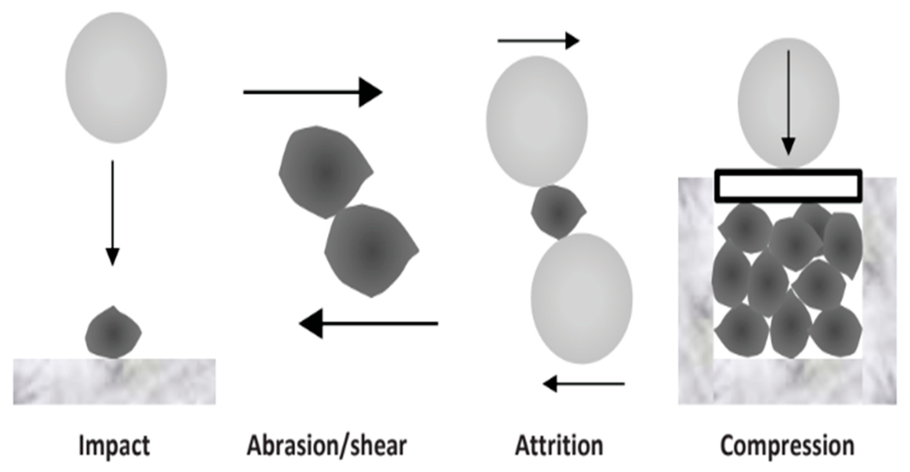


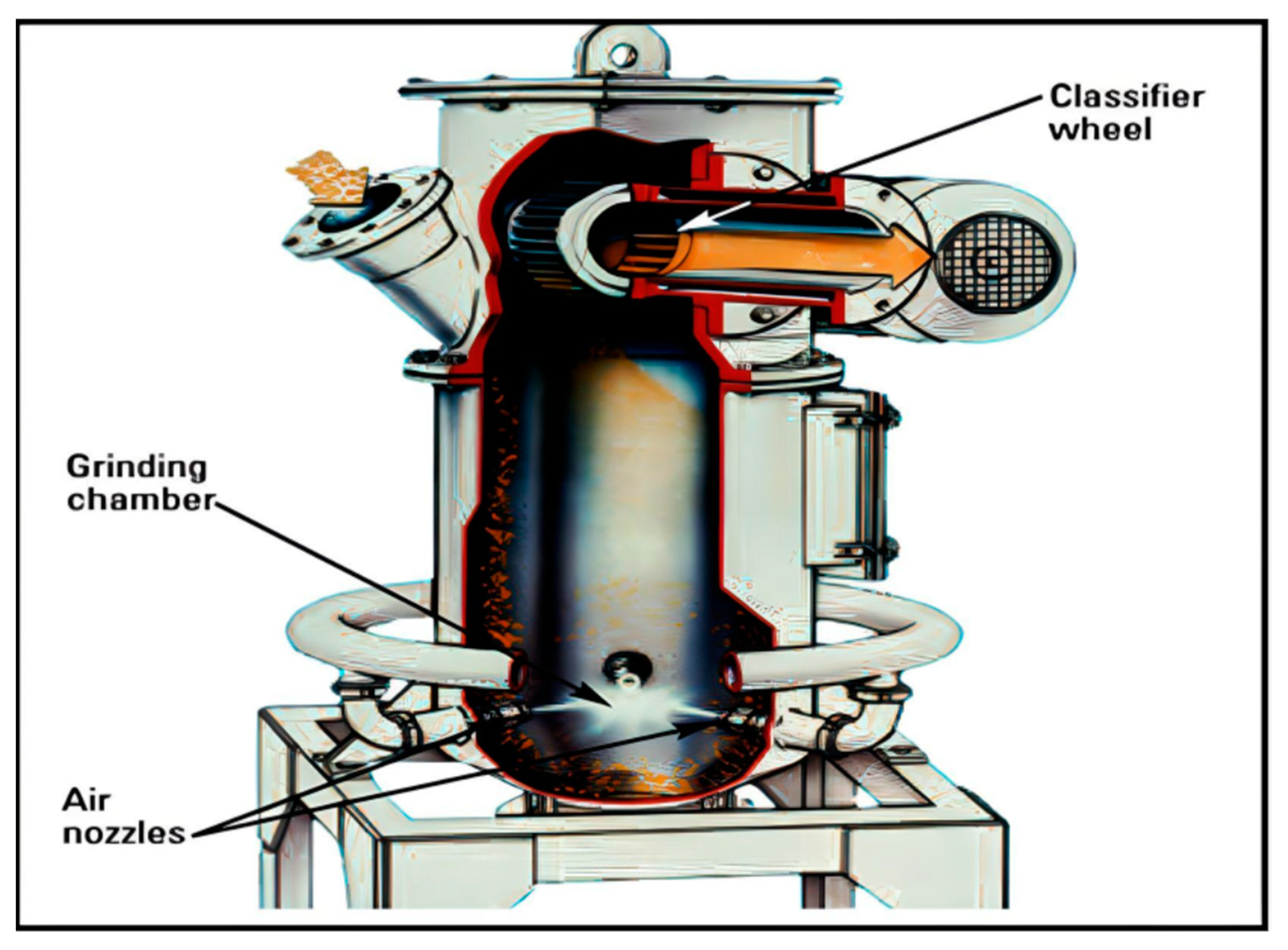