Article

Thrust Coordinated Assignment and Ripple Suppression of a Multiple-Modular Permanent Magnet Linear Synchronous Motor Based on Model Predictive Thrust Control

1
College of Safety and Ocean Engineering, China University of Petroleum, Beijing 102249, China
2
CNOOC Ener Tech-Drilling & Production Co., Tianjin 300452, China
3
School of Electrical and Information Engineering, Jiangsu University, Zhenjiang 212013, China
*
Author to whom correspondence should be addressed.
Energies 2023, 16(14), 5368; https://doi.org/10.3390/en16145368
Submission received: 22 May 2023 / Revised: 1 July 2023 / Accepted: 11 July 2023 / Published: 14 July 2023
(This article belongs to the Special Issue Advanced Modeling and Optimization of Electrical Drives Technology)

Abstract

:
This paper presents a model predictive thrust force control (MPTFC) method for a multiple-modular permanent magnet synchronous linear motor (PMSLM). It focuses on the thrust assignment and thrust ripple of the motor drive system with a multiple-branch inverter. A discrete time model of the PMSLM is established, and the driving system structure and operation principle of the motor are studied. A multi-mode cost function is designed according to the requirements of the different load conditions, and the optimal voltage vector action time is determined. The operation mode is analyzed to determine the distribution factor, so as to reduce the thrust pulsation during operation and improve the performance of the drive system. The results indicate that the proposed MPTFC method is effective in different operating modes, and the drive system has high efficiency and safer performance compared to a conventional drive system.

1. Introduction

Recently, with the increasing demand for precision and response speed of the intelligent equipment drive, the permanent magnet linear synchronous motor (PMLSM) features large thrust, high speed, fast dynamic response, etc. has been taken a lot of attentions compared with the traditional linear motion device composed of rotating motors and mechanical transmission components. It has broad application prospects in intelligent manufacturing, aerospace, logistics transmission and other linear motion driving occasions [1,2,3]. However, compared with the traditional rotating motor, the PMLSM has a unique end effect due to the axial breaking of the primary winding core. On the one hand, the disconnection end effect is coupled with the cogging effect, which leads to the distortion of the air gap magnetic field [4,5]. On the other hand, it leads to the discontinuous arrangement of the motor primary winding, the long connecting wire, and the asymmetric winding parameters. The existence of the end effect, the cogging effect and the asymmetry of winding parameters make the thrust and normal attraction of the PMLSM fluctuate greatly. Although these fluctuations can be effectively reduced by optimizing the pole slot coordination and the end structure, the thrust performance of the motor is often sacrificed. In addition, the disturbance and current distortion during operation will further worsen these fluctuations. Therefore, how to effectively suppress the thrust fluctuation to improve the dynamic performance and reliability of the PMLSM drive system is still one of the difficulties to be solved in the further promotion and application of permanent magnet linear synchronous motor in the fields of precision intelligent manufacturing, linear transmission, aerospace and other drive fields.
In terms of logistics transmission systems, especially automated warehousing systems, efficient and high-precision driving of the goods is crucial. The traditional belt pulley transportation method cannot achieve precise positioning, and there are significant fluctuations during the transportation process, which has a significant impact on fragile goods such as glass, and leads to low overall system efficiency. The PMLSM can achieve precise linear position control, which is very suitable for warehouse automation transmission systems. Yet, compared with traditional rotating motor, the permanent magnet linear synchronous motor (PMLSM) has large ripples in thrust and normal attraction due to the end effect, the cogging effect and the asymmetry of the winding parameters. For this reason, many experts and scholars have proposed a variety of control strategies to effectively suppress thrust ripple, including compensation and improved control algorithms. Specifically, the predictive control, adaptive control, neural network control, iterative learning control, etc. are introduced to reduce the thrust pulsation while improving the robustness and anti-interference ability of the system, which has been applied in many fields. Those provides great inspiration for the PMLSM application.
However, for automated warehousing applications, due to the difference in weight, volume, shape and attributes, including fragility, liquid or gaseous state, etc., of the carrying items being transported, different requirements are imposed on the transmission drive system [6,7,8], as shown in Figure 1. When some fragile products and flammable and explosive products are stored, excessive acceleration and deceleration will have a greater impact on the commodities, possibly resulting in collision damage [9,10]. At the same time, in order to improve the efficiency, the system should accelerate and decelerate as quickly as possible, especially for some heavier carrying items [11,12]. Hence, the complex and ever-changing storage goods demands and transportation conditions pose strict requirements for the linear motor system. In order to improve the automatic storage system efficiency and quality, how to realize multiple-modular PMLSM control and reduce thrust ripple is particularly important.
As for the control of the permanent magnet linear motors, many experts and scholars have proposed control strategies to effectively suppress thrust ripple, mainly including compensation and improved control algorithms [13,14]. As far as the compensation control strategy is concerned, the mathematical models of thrust ripple components are established. A simplified mathematical model is obtained through theoretical analysis, finite element simulation or experimental data fitting, and then it is compensated online [3,15]. In [16], Fourier analysis was performed on the position loop output of the motor, and curve-fitting was performed to obtain the linear relationship between the thrust ripple and the position loop control parameter output. As far as the improved control strategy is concerned, predictive control [17,18], adaptive control [19], neural network control [20,21], iterative learning control [22,23], etc., are introduced to reduce the thrust pulsation while improving the robustness and anti-interference ability. However, the advanced control algorithms have a high dependence on the computational ability of the driving control system, and there are various matching problems in practical applications.
In recent years, in order to availably reduce the end force, cogging force and thrust fluctuation effect and improve the reliability of the permanent magnet linear drive system, the concept of modularization has been introduced into the PMLSM [24,25]. A variety of the modular PMLSMs have been proposed. This type of modular PMLSM mainly includes primary unit combination modularization and slot unit modularization [26,27]. Yet, as the key point of the PMLSM system, the efficient drive, high thrust and low thrust ripple are important indicators of high-quality linear drive [28]. Hence, how to effectively reduce the ripple and improve the stability of the PMLSM still faces various challenges.
In this paper, a model predictive direct thrust control method is proposed by considering multiple operation conditions for the multiple-module permanent magnet linear synchronous motor which is used in automated warehousing application. In order to improve the response of the motor and reduce the thrust ripple, a combination thrust target is proposed based on the complex operating conditions of the carrying item line system where an online optimization assignment is adopted. The paper is organized as follows. In Section 2, the topology and the multiple-branch inverter of the multiple-modular PMSLM are introduced. Moreover, the multiple operation conditions are discussed. In Section 3, the model predictive thrust force control method is given and investigated in detail. In Section 4, the content of the experiment is introduced and analyzed in detail. Finally, Section 5 summarizes the full paper.

2. Topology and Multiple Operating Mode of the Multiple-Modular PMSLM

2.1. Topology of the MM-PMSLM Driving System

The multiple-modular PMSLM consists of two mover modules, each with 21 slots, in which a centralized coil is used, as shown in Figure 2a. Each module has a series of seven coils with concentrated windings.
The two movers of the modular permanent magnet synchronous linear motor are face to face. The distance χ between the two movers is set so that χ = , forming an alternating symmetric induced electromotive force, where τ is the stator pole distance and k = 1, 3, 5… In order to increase the power, the modules of the PMLSM can be increased horizontally or vertically. Figure 2b shows a multi-channel inverter consisting of six half-bridges, with two Y-connected windings connected to each of the six channels. The A1, B1, and C1 forms the windings of the mover module A. The A2, B2, and C2 form the windings of the module B. The same control frequency is set so that both mover modules move at the same speed. To meet the requirements of force ripple and variable loads, the currents of the two mover modules can be different. In addition, by controlling the switching device of the multi-channel inverter, the three-phase windings of the two modules in the PMSLM can be connected in series or in parallel, so as to achieve fast acceleration/deceleration, slow acceleration/deceleration and other motion modes. Overall, the modular drive structure puts forward more stringent requirements for the response speed and control effectiveness of the drive control system.

2.2. Multiple Operating Mode for Automated Warehousing

On an automated warehousing line, the weights of different items are different, and the conveyor belt is significantly affected by load disturbances, which ultimately lead to instability and low efficiency of the delivery system. Based on the operating data of the typical automated warehousing line [29], the typical operating conditions (TOC) are divided into three modes, namely, low load with uniform motion (I), low load with slowed-down motion (II) and heavy load with accelerated motion (III). According to the nature of the carrying items to be transported, the operating conditions at the start or stop of transport can be selected, as shown in Table 1.

3. Model Predictive Thrust Force Control

Model predictive thrust force control (MPTFC) is a control strategy based on a motor model. The MPTFC method proposed in this paper selects different distribution factors according to the properties of the goods and then determines the thrust and acceleration to meet different operation requirements.
The thrust and flux linkage are controlled by the online look-up table method, and the active voltage vector is determined by the cost function calculation. For a two-level, three-phase inverter, there are six non-zero voltage vectors. In each sampling period, the action of each voltage vector is calculated, and the voltage vector with the smallest corresponding cost function is selected to act on the inverter. A three-vector model predictive thrust force control strategy is cited. The strategy acts on three voltage vectors in one sampling period, and through two voltage vector selections, two effective voltage vectors are obtained, and the third voltage vector is the zero vector. The action time of each voltage vector is calculated according to the deadbeat control.
Because the two mover modules are set to face each other, and the distance between the two modules is an odd multiple of the pole pitch, the electrical starting positions of the two modules are the same, and the reference thrust of the A module can be used as the reference thrust of the B module (FeA* = FeB*). Affected by the requirements of the operating conditions, the forces of the two modules are not necessarily equally divided. Therefore, the thrust force coordinated control (TFCC) is used to meet the needs of different working conditions. Based on the analysis of the different working conditions, the TFCC is investigated, and through the force control of the two modules, the force fluctuation can be effectively suppressed. The total thrust force Fe is given as follows for the two modules:
F e = F e A + λ F e B
In Operation I: The output power and electromagnetic thrust are provided by mover module A. Due to λ = 0, mover module B outputs an electromagnetic field of 0 N.
In Operation II: Mover module A drives the motor, providing forward electromagnetic thrust due to −1 < λ < 0. Mover module B is now in a braking state. When the goods start or stop transportation, mover module B provides reverse electromagnetic thrust to reduce the acceleration during the start or stop and increase the response time. Due to the limited load capacity of the motor, it is necessary to ensure a certain amount of electromagnetic thrust. The setting of λ cannot be too small.
In Operation III: Mover modules A and B both output positive electromagnetic thrust at this time (i.e., 0 < λ ≤ 1), and the motor outputs the maximum electromagnetic thrust. When goods are transported and stopped, they can obtain greater acceleration and respond faster.
It is worth noting that the value of λ in the above three typical operating conditions is only determined at the initial stage and does not change during the entire operation. It is difficult to adapt to different start–stop and frequent variable speed operating conditions. Therefore, in order to meet the various working conditions, the value of λ needs to be adjusted between the two modules.

3.1. Selection Principle of λ in Different Conditions

Based on the application background of three-dimensional automated warehousing, in order to meet the different conditions, the constraint formula of λ in the TFCC selection principle is derived.
(1)
Low load
This condition does not need to consider the fragility of the item. When there are many shipments (more), focus on transportation efficiency and choose Operation III. In the contrary situation (less), in order to improve the module utilization rate, Operation I should be selected. The selection principle of λ can be expressed as:
λ = { 1   ,   m o r e 0   ,   l e s s
(2)
Heavy load
Under heavy load conditions, focusing on transportation efficiency and taking into account a certain degree of safety, it should be possible to speed up the start-up. At the same time, in order to avoid excessive deceleration that will cause the carrying items to have a greater impact on the transport pallet, the deceleration should be slow. The maximum output thrust of a single module is set as FeAmax, and when the load FL is greater than FeAmax, it is a heavy load. λ can be expressed as:
λ = { 1                                     , Δ v * > 0 λ k 1                         , Δ v * = 0 2 α F L / F e A max   , Δ v * < 0
where α is an adjustable factor and its initial value is 1. By changing its value, the deceleration effect can be enhanced or weakened. When decelerating, the larger the load, the larger the potential energy, so the deceleration should be smaller, meaning a smaller value of λ.
(3)
Fragile load
In the case of fragile carrying items, safety should be paid attention, and efficiency should be considered at the same time. In addition, excessive acceleration and deceleration should be avoided. The G value is usually used to indicate the fragility of the carrying items. It refers to the ratio of the maximum acceleration a to the gravitational acceleration g (G = a/g) that the product can withstand without physical damage or functional failure. The limit G refers to the physical limit G0 at which the product does not suffer physical damage or functional failure. The allowable G is based on G0, taking into account factors such as the value, strength and importance of the product, divided by a safety factor n greater than 1 and expressed by:
[ G ] = | a | g G 0 n
Hence, the allowable maximum acceleration a0 during transportation can be obtained as:
a 0 = g G 0 n
The maximum acceleration that the motor can achieve is set to amax. If a0 is less than amax, combined with the mechanical motion equation of the motor, λ can be described as follows:
λ = { M a 0 + F L F e A max 1   , Δ v * > 0 λ k 1   , Δ v * = 0 M a 0 + α F L F e A max 1   , Δ v * < 0
where M is the equivalent mass. In order to ensure enough thrust such that the system can run normally, the minimum value of λ is:
λ min = F L F e A max 1
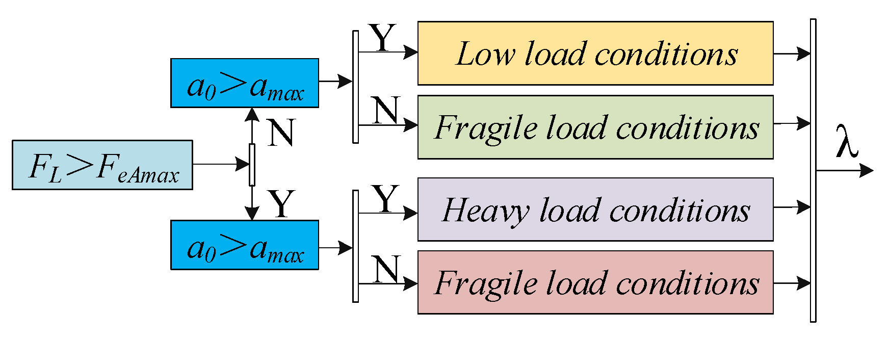
The λmin value only acts as a constraint. Comparing FL with the electromagnetic thrust FeAmax, the maximum allowable acceleration a0 and the maximum acceleration amax that can be achieved can be used to judge the working conditions including light load, heavy load and fragile load for λ, as shown in Figure 3.
The algorithm mentioned above considers different working conditions of automated warehousing lines, and based on the weight and attributes of the items, determines the working conditions: light load, heavy load or fragile load. From this, the allocation factor is selected to determine the magnitude of the thrust and acceleration. The thrust and acceleration determined under this method are more in line with the needs of cargo transportation, avoiding issues such as thrust mismatch with load and excessive thrust pulsation, and ensuring efficiency and safety during cargo transportation.

3.2. Reference Flux Calculation and Current Prediction Model

Based on the id = 0 control strategy, the reference flux can be calculated as
{ Ψ s A * = ( 2 τ F e A * L s A / 3 π p n Ψ f A ) 2 + Ψ f A 2 Ψ s B * = ( 2 τ λ F e B * L s B / 3 π p n Ψ f B ) 2 + Ψ f B 2
where ψf is the flux linkage produced by the PMs, pn is the pole pairs of the motor and Ls is the inductance of the motor. λ is the thrust distribution factor. The right subscripts A and B denote the respective modules. The prediction model of current can be obtained by the Euler discrete formula:
{ i d A k + 1 = i d A k + [ ( R s A i d A k + π τ v e L s A i d A k + u d A k ) T s ] / L s A i d B k + 1 = i d B k + [ ( R s B i d B k + π τ v e L s B i d B k + u d B k ) T s ] / L s B i q A k + 1 = i q A k + [ ( R s A i q A k + π τ v e L s A i q A k π τ v e Ψ f A + u q A k ) T s ] / L s A i q B k + 1 = i q B k + [ ( R s B i q B k + π τ v e L s B i q B k π τ v e Ψ f B + u q B k ) T s ] / L s B
where Ts is the sampling time and τ is the pole distance.

3.3. Thrust Force and Flux Estimator and Cost Function

For the PMSLM, the magnetic flux of the mover can be calculated using a voltage or current model. However, the voltage model of the PMSLM contains an integration operation link. Instability of the DC power supply and changes in the initial value of the integrator can affect the accuracy of the voltage model, thereby affecting the entire drive system. Too large DC bus voltage offset and too large initial value are easy to saturate the integrator, which may resulting in the unstable operation of the whole power system. Therefore, this article calculates the PMSLM flux based on the current model. In a two-phase stationary coordinate system, the d-q axis magnetic flux can be represented as follows:
[ Ψ d A k + 1 Ψ q A k + 1 Ψ d B k + 1 Ψ q B k + 1 ] = [ L A 0 0 0 0 L A 0 0 0 0 L B 0 0 0 0 L B ] [ i d A k + 1 i q A k + 1 i d B k + 1 i q B k + 1 ] + [ Ψ f A k + 1 0 Ψ f B k + 1 0 ]
The estimated value of the mover flux amplitude ψs is:
Ψ s A k + 1 = ( Ψ d A k + 1 ) 2 + ( Ψ q A k + 1 ) 2 ,   Ψ s B k + 1 = ( Ψ d B k + 1 ) 2 + ( Ψ q B k + 1 ) 2
Hence, the estimated value of the electromagnetic thrust in the d-q coordinate system can be expressed as:
F e k + 1 = F e A k + 1 F e B k + 1 = 1.5 p n π τ ( φ f A k + 1 i q A k + 1 φ f B k + 1 i q B k + 1 )
Because the two motor modules actually run in opposite directions, synchronous operation is only possible given opposite speeds. Therefore, thrusts of opposite signs will produce thrusts in the same direction. The minimum cost function is as follows:
{ m i n { g i A } = | F e A * F e A k + 1 | + μ A | | Ψ s A * | | Ψ s A k + 1 | | m i n { g i B } = | λ F e B * F e B k + 1 | + μ B | | Ψ s B * | | Ψ s B k + 1 | |
where Fe* and φs* are the reference values of the thrust and mover flux, respectively. Fek+1 and φsk+1 are the predicted values of the thrust and mover flux at the (k + 1)th sampling period, respectively. μ is the weighting factor to balance the two variables with different units, which is chosen as FN/ψsN.

4. Experimental Verification

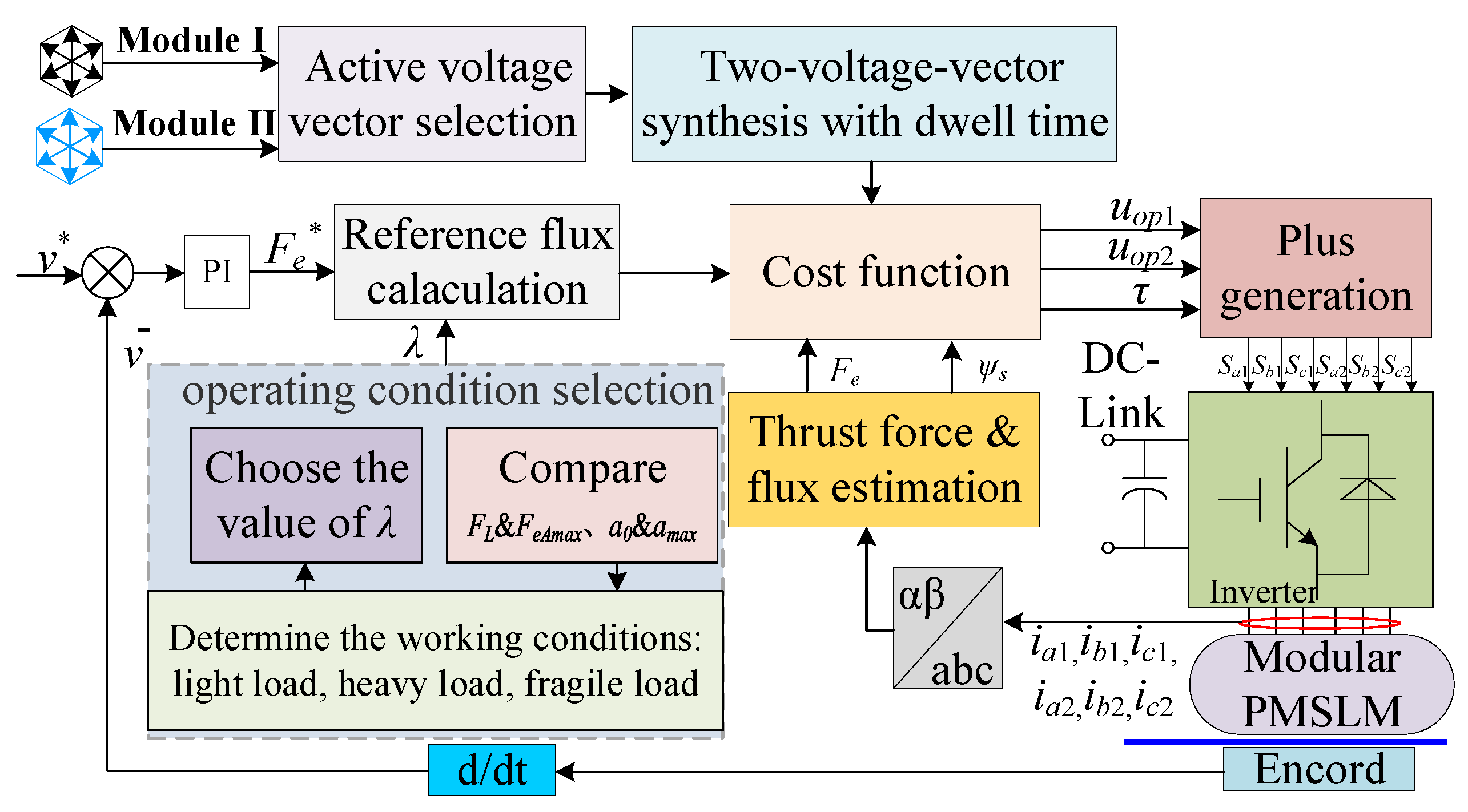
A diagram of the model predictive thrust force control (MPTFC) method is shown in Figure 4. This control strategy adds a distribution factor on the basis of thrust control. The distribution factor is selected according to the property of the item; the method then determines the output thrust of the drive system and then determines the start and stop acceleration. The MPTFC combines the characteristics of both MPC and DTC.
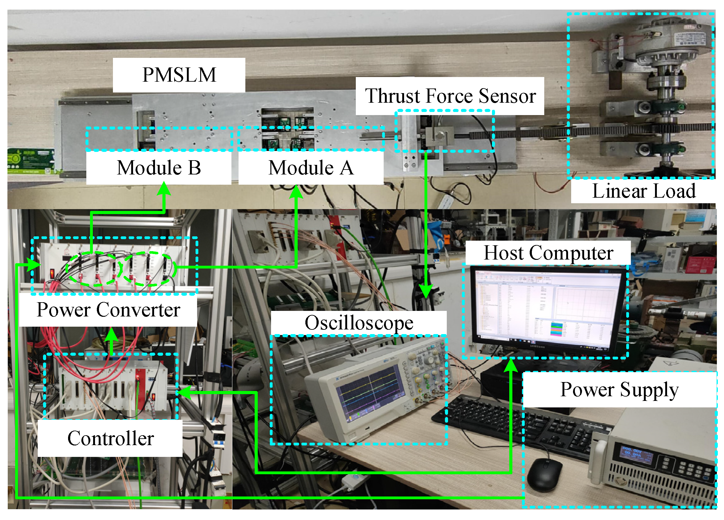
To verify the effectiveness of the proposed MPTFC method, an experimental platform based on an RTU-BOX204 unit was built, as shown in Figure 5. It should be noted that the control core consists of a TMS320F28346 from Texas Instruments Incorporated and four FPGAs from Xilinx Incorporated is adopted. The platform uses linear Hall sensors to obtain position signals, uses magnetic powder brakes to load the PMSLM and uses sensors to measure the thrust in real time. A Half-bridge power converter where the maximum current is 25A with six branches is utilized. The parameters of the multiple-modular PMLSM method are shown in Table 2. The proposed method is compared with the traditional SVPWM control method. The sampling frequency is 3 kHz.
(1)
Low load condition: Figure 6 shows the dynamic performance of the two control methods. The proposed method does not consider module utilization as well. The speed varies from 0 cm/s–4 cm/s–0 cm/s. The load force is set to 60 N. Due to the adopted MPTC control, the current response is better, and the acceleration and deceleration speeds are faster than those of the SVPWM control method. The thrust ripple of the proposed method is 26.7%, and that of the traditional SVPWM is 43.3%.
(2)
Heavy load condition: Figure 7 shows the dynamic response of the two methods under heavy load. The speed varies from 0 cm/s–4 cm/s–0 cm/s. The reference load force is set to 100 N. To simulate heavy load conditions, α is increased accordingly. The thrust ripple of the proposed method is 10%, and that of the traditional SVPWM method is 22%.
(3)
Fragile load condition: The dynamic response of the two methods under the fragile load condition is shown in Figure 8. The speed varies from 0 cm/s–4 cm/s–0 cm/s. The load force is set to 60 N. The allowable maximum acceleration a0 is 1.8 m/s2. The maximum acceleration at the start is reduced from 2.5 m/s2 to 1.7 m/s2, and that at the stop is reduced from 2 m/s2 to 1.7 m/s2. The thrust ripple of the proposed method is 38.3%, and that of the traditional SVPWM method is 16.7%.
Table 3 shows the thrust ripple situation of the motor under two control strategies. It can be clearly seen that compared to the traditional SVPWM control strategy, the control strategy proposed in this article has smaller thrust ripple under different working conditions of light load, heavy load and fragile load. It can be concluded that the model prediction thrust control method considering the distribution factor can effectively suppress thrust ripple during the operation of the linear motor.
Table 4 shows the response performance of the motor. Under a low load, the response performance of the proposed method is significantly improved. In heavy load conditions, the start-up response of the proposed method is faster, and the stop response is slower. While ensuring efficiency, it also takes safety into account. In fragile load conditions, the start and stop responses of the proposed method are slower. While ensuring safety, it also takes efficiency into account. Due to the limited experimental conditions, the a0 is set to a small value for fragile loads, but the proposed method is still effective after proportional enlargement.

5. Conclusions

In this paper, by considering variable operating conditions of automated warehousing, an MPTFC method for a multiple-modular PMLSM is investigated with a multi-branch inverter. Three different load cases are selected in variable operating conditions, and a detailed study was conducted on the proposed MPTFC method. The control principle and mathematical model are discussed and deduced. Multiple distribution factors are chosen to determine the thrust magnitude and operating acceleration in order to optimize the output thrust and thrust ripple. Finally, a semi-physical simulation platform based on an RTUBOX-204 unit is established for experimental verification. Comparing the proposed MPTFC and traditional SVPWM control methods, under the conditions of low load, heavy load and fragile load, the thrust ripple of the proposed method is reduced by 16.6%, 12%, and −21.6%, respectively, compared with the traditional SVPWM method, and the thrust ripple amplitude is reduced by 10 N, 12 N, and 13 N, respectively. The MPTFC method has a better response performance and a smaller thrust ripple value; therefore, the proposed method is correct and effective.

Author Contributions

Conceptualization, K.Z. and J.Y.; methodology, L.X. and Y.H.; software, B.L. and H.L.; validation, H.Q., L.L. and H.L.; formal analysis, K.Z.; investigation, K.Z.; resources, Y.H.; data curation, H.L.; writing—original draft preparation, K.Z.; writing—review and editing, J.Y.; visualization, H.Q.; supervision, B.L.; project administration, K.Z.; funding acquisition, K.Z. All authors have read and agreed to the published version of the manuscript.

Funding

This research received no external funding.

Data Availability Statement

Where no new data were created.

Conflicts of Interest

The authors declare no conflict of interest.

References

  1. Hu, H.; Liu, X.; Zhao, J.; Guo, Y. Analysis and Minimization of Detent End Force in Linear Permanent Magnet Synchronous Machines. IEEE Trans. Ind. Electron. 2017, 65, 2475–2486. [Google Scholar] [CrossRef]
  2. Xu, L.; Zhu, X.; Wu, W.; Fan, W.; Zhou, X.; Cai, X.; Quan, L. Flux-leakage design principle and multiple-operating conditions modeling of flux leakage controllable PM ma-chine considering driving cycles. IEEE Trans. Ind. Electron. 2022, 69, 8862. [Google Scholar] [CrossRef]
  3. Li, B.; Zhao, J.; Liu, X.; Guo, Y.; Hu, H.; Li, J. Detent force reduction of an arc-linear permanent magnet synchronous motor by using compensation windings. IEEE Trans. Ind. Electron. 2017, 64, 3001. [Google Scholar] [CrossRef] [Green Version]
  4. Yang, H.; Bai, Y.; Chien, Y. Generalized super-twisting sliding mode control of permanent magnet synchronous motor based on sinusoidal saturation function. IEICE Electron. Express 2022, 19, 20220066. [Google Scholar] [CrossRef]
  5. Xu, L.; Zhu, X.; Fan, W.; Zhang, C.; Zhang, L.; Quan, L. Comparative analysis and design of partitioned stator hybrid excitation axial flux switching PM motors for in-wheel traction applications. IEEE Trans. Energy Convers. 2022, 37, 1416. [Google Scholar] [CrossRef]
  6. Yoshitake, H.; Kamoshida, R.; Nagashima, Y. New Automated Guided Vehicle System Using Real-Time Holonic Scheduling for Warehouse Picking. IEEE Robot. Autom. Lett. 2019, 4, 1045–1052. [Google Scholar] [CrossRef]
  7. Zhang, F.; Shang, W.; Zhang, B.; Cong, S. Design optimization of redundantly actuated cable-driven parallel robots for automated warehouse system. IEEE Access 2020, 8, 56867. [Google Scholar] [CrossRef]
  8. Digani, V.; Sabattini, L.; Secchi, C. A probabilistic eulerian traffic model for the coordination of multiple AGVs in automatic warehouses. IEEE Rob. Autom. Lett. 2016, 1, 26. [Google Scholar] [CrossRef]
  9. Prakash, R.; Behera, L.; Mohan, S.; Jagannathan, S. Dual-Loop Optimal Control of a Robot Manipulator and Its Application in Warehouse Automation. IEEE Trans. Autom. Sci. Eng. 2020, 19, 262–279. [Google Scholar] [CrossRef]
  10. Lian, Y.; Xie, W.; Yang, Q.; Liu, Y.; Yang, Y.; Wu, A.G.; Eisaka, T. Improved coding landmark-based visual sensor position measurement and planning strategy for multi-warehouse automated guided vehicle. IEEE Trans. Instrum. Meas. 2022, 71, 3509316. [Google Scholar] [CrossRef]
  11. Basile, F.; Chiacchio, P.; Coppola, J. A Hybrid Model of Complex Automated Warehouse Systems—Part I: Modeling and Simulation. IEEE Trans. Autom. Sci. Eng. 2012, 9, 640–653. [Google Scholar] [CrossRef]
  12. Du, Y.; Mao, Y.; Xiao, F.; Zhu, X.; Sun, Y.; Quan, L. A Pole-Changing Doubly Salient Permanent Magnet Motor. IEEE Trans. Transp. Electrif. 2022, 8, 2479–2489. [Google Scholar] [CrossRef]
  13. Fu, D.; Zhao, X.; Yuan, H. High-precision motion control method for permanent magnet linear synchronous motor. IEICE Electron. Express 2021, 18, 20210097. [Google Scholar] [CrossRef]
  14. Zhang, C.; Xu, L.; Zhu, X.; Du, Y.; Quan, L. Elimination of DC-Link Voltage Ripple in PMSM Drives with a DC-Split-Capacitor Converter. IEEE Trans. Power Electron. 2020, 36, 8141–8154. [Google Scholar] [CrossRef]
  15. Zhao, W.; Zheng, J.; Wang, J.; Liu, G.; Zhao, J.; Fang, Z. Design and Analysis of a Linear Permanent-Magnet Vernier Machine with Improved Force Density. IEEE Trans. Ind. Electron. 2015, 63, 2072–2082. [Google Scholar] [CrossRef]
  16. Bascetta, L.; Rocco, P.; Magnani, G. Force ripple compensation in linear motors based on closed-loop position-dependent identification. IEEE/ASME Trans. Mechatron. 2010, 15, 349. [Google Scholar] [CrossRef]
  17. Lim, C.S.; Rahim, N.A.; Hew, W.P.; Levi, E. Model Predictive Control of a Two-Motor Drive with Five-Leg-Inverter Supply. IEEE Trans. Ind. Electron. 2012, 60, 54–65. [Google Scholar] [CrossRef]
  18. Shi, X.; Lan, Y. Improved predictive position control for linear synchronous motor with disturbance observer. IEICE Electron. Express 2022, 19, 20220375. [Google Scholar] [CrossRef]
  19. Yao, B.; Hu, C.; Lu, L.; Wang, Q. Adaptive Robust Precision Motion Control of a High-Speed Industrial Gantry with Cogging Force Compensations. IEEE Trans. Control Syst. Technol. 2011, 19, 1149–1159. [Google Scholar] [CrossRef]
  20. Wang, Z.; Hu, C.; Zhu, Y.; He, S.; Yang, K.; Zhang, M. Neural Network Learning Adaptive Robust Control of an Industrial Linear Motor-Driven Stage with Disturbance Rejection Ability. IEEE Trans. Ind. Inform. 2017, 13, 2172–2183. [Google Scholar] [CrossRef]
  21. Marino, P.; Milano, M.; Vasca, F. Linear quadratic state feedback and robust neural network estimator for field-oriented-controlled induction motors. IEEE Trans. Ind. Electron. 1999, 46, 150. [Google Scholar] [CrossRef]
  22. Mandra, S.; Galkowski, K.; Rogers, E.; Rauh, A.; Aschemann, H. Performance-Enhanced Robust Iterative Learning Control with Experimental Application to PMSM Position Tracking. IEEE Trans. Control Syst. Technol. 2018, 27, 1813–1819. [Google Scholar] [CrossRef] [Green Version]
  23. Lin, Z.; Wang, J.; Howe, D. A Learning Feed-Forward Current Controller for Linear Reciprocating Vapor Compressors. IEEE Trans. Ind. Electron. 2010, 58, 3383–3390. [Google Scholar] [CrossRef]
  24. Tan, Q.; Huang, X.; Li, L.; Wang, M. Magnetic field analysis and flux barrier design for modular permanent magnet linear synchronous motor. IEEE Trans. Ind. Electron. 2020, 67, 3891. [Google Scholar] [CrossRef]
  25. Cao, R.; Cheng, M.; Zhang, B. Speed Control of Complementary and Modular Linear Flux-Switching Permanent-Magnet Motor. IEEE Trans. Ind. Electron. 2015, 62, 4056–4064. [Google Scholar] [CrossRef]
  26. Zhang, Z.; Tang, X.; Zhang, C.; Li, M. Comparative study on modular longitudinal and transverse flux-switching permanent magnet linear motor. IEEE Trans. Energy Convers. 2020, 35, 33. [Google Scholar] [CrossRef]
  27. Zhao, W.; Yao, T.; Xu, L.; Chen, X.; Song, X. Multi-objective optimization design of a modular linear permanent magnet vernier machine by combined approximation models and differential evolution. IEEE Trans. Ind. Electron. 2021, 68, 4634. [Google Scholar] [CrossRef]
  28. Zhao, W.; Cheng, M.; Ji, J.; Cao, R.; Du, Y.; Li, F. Design and analysis of a new fault-tolerant linear permanent-magnet motor for maglev transportation ap-plications. IEEE Trans. Appl. Supercond. 2012, 22, 5200204. [Google Scholar] [CrossRef]
  29. Basile, F.; Chiacchio, P.; Coppola, J. A Hybrid Model of Complex Automated Warehouse Systems—Part II: Analysis and Experimental Results. IEEE Trans. Autom. Sci. Eng. 2012, 9, 654–668. [Google Scholar] [CrossRef]
Figure 1. Automated warehousing demands for motor drive system.
Energies 16 05368 g001
Figure 2. Modular PMSLM and inverter topology. (a) Modular PMSLM. (b) Inverter.
Energies 16 05368 g002
Figure 3. The process of operating condition selection.
Energies 16 05368 g003
Figure 4. Control diagram of the proposed MPTFC.
Energies 16 05368 g004
Figure 5. Experimental platform and control system for the PMSLM.
Energies 16 05368 g005
Figure 6. Measured waveforms in low load conditions. (a) Conventional SVPWM. (b) Proposed method.
Energies 16 05368 g006
Figure 7. Measured waveforms under heavy load conditions. (a) Conventional SVPWM. (b) Proposed method.
Energies 16 05368 g007
Figure 8. Measured waveforms in fragile carrying items conditions. (a) Conventional SVPWM. (b) Proposed method.
Energies 16 05368 g008
Table 1. Operating conditions selection.
ItemsStartStop
Low loadI/IIII/III
Heavy loadIIIII
Low and fragile loadIIII
Heavy and fragile loadIIIII
Table 2. Parameters of module A or B.
ParametersValuesParametersValues
Udc (V)24Ψf (Wb)0.006
VN (m/s)0.2Ls (mH)4.0
IN (A)5Rs (Ω)2.75
Table 3. Thrust ripple.
MethodsThrust Ripple
(Low Load)
Thrust Ripple
(Heavy Load)
Thrust Ripple
(Fragile Load)
Conventional SVPWM26 N22 N23 N
Proposed methods16 N10 N10 N
Table 4. Response performance.
MethodsStart Response Time
(Low Load/Heavy Load/Fragile Load)
Stop Response Time
(Low Load/Heavy Load/Fragile Load)
Conventional SVPWM24 ms/26 ms/24 ms30 ms/28 ms/30 ms
Proposed methods16 ms/18 ms/40 ms28 ms/32 ms/40 ms
Disclaimer/Publisher’s Note: The statements, opinions and data contained in all publications are solely those of the individual author(s) and contributor(s) and not of MDPI and/or the editor(s). MDPI and/or the editor(s) disclaim responsibility for any injury to people or property resulting from any ideas, methods, instructions or products referred to in the content.