Article

Performance Improvement of Permanent-Magnet-Synchronous Motors through Rotor Shape Optimization of Marine Blowing System with High-Speed Rotation

1
Department of Electrical Engineering, Honam University, 120, Honamdae-gil, Gwangsan-gu, Gwangju 62399, Republic of Korea
2
Smart Electrics Research Center, Korea Electronics Technology Institute, 226, Cheomdangwagi-ro, Buk-gu, Gwangju 61011, Republic of Korea
*
Author to whom correspondence should be addressed.
Energies 2023, 16(14), 5486; https://doi.org/10.3390/en16145486
Submission received: 30 May 2023 / Revised: 23 June 2023 / Accepted: 14 July 2023 / Published: 19 July 2023
(This article belongs to the Section F: Electrical Engineering)

Abstract

:
Currently, research is being carried out on the performance improvement of permanent-magnet-synchronous motors (PMSM) used in air conditioning and blowing systems for marine, as well as structural research, regarding their high-speed operation. Surface-mounted permanent magnet (SPM) motors used in marine propulsion and air-conditioning systems have the advantages of easy rotor manufacturing and a simple structure. However, owing to the structural characteristics associated with attaching a permanent magnet to the surface of the rotor, there is a risk of permanent magnet scattering when turning a rated load at high speed, and the rotor assembly is directly affected by the heat generated in the stator winding. Therefore, in this study, additional protrusions were proposed to prevent rotor scattering during high-speed operations. Additionally, optimization was performed to reduce the torque ripple at the rated load and the total harmonic distortion (THD) of the no-load-induced electromotive-force waveform generated by the protrusion. Consequently, the risk of scattering at high speeds was improved by securing the bonding force of the permanent magnet using the proposed structure, and the THD and torque ripple were reduced compared with those of the basic model through optimization. In addition, rotor structural stress analyses were conducted to solve the problem of scattering at high speeds and eigenmode analysis.

1. Introduction

Global warming is a major global concern. Therefore, the use of clean and renewable energy sources with low environmental pollutant emissions has emerged as an important issue in all industrial fields. As part of these countermeasures, hybrid driving systems have already been commercialized in the field of transportation, and pure electric driving systems are proliferating. In marine vessels, the high efficiency of electric motors has been promoted, along with the widespread use of electronic devices. In particular, motor-driven electric propulsion ships using hybrid concepts have been introduced [1].
Air-conditioning and blowing systems in ships are only partially applied to special-purpose ships that require excellent driving performance at low speed, low noise, and low vibration characteristics, and to transport ships that place importance on increased interior space for comfort. However, with the recent increase in operating costs owing to high oil prices and the strengthening of international regulations on greenhouse gas reduction, the applications of high-performance electric-propulsion systems are proliferating, even in general ships [2,3,4].
Various motors are used air-conditioning and blowing systems in ships. Induction motors are widely used, easy to manufacture, robust, and have a simple structure. They have the advantages of low cost and ease of maintenance. However, the efficiency of an induction motor is low at low speeds, and the heat loss of the rotor reduces its efficiency and power factor. Therefore, the use of permanent-magnet-synchronous motors (PMSM), which have good efficiency and power factors and can operate at high speeds, is increasing [5]. Because PMSMs use permanent magnets with high-energy density as the rotating body, it is easy to increase the capacity, as well as reduce the volume and weight of the motor. In addition, they have excellent instantaneous maneuverability compared with induction motors, and a large output compared with their volume and weight. In addition, a separate excitation current is not required for magnetic flux generation; therefore, the energy efficiency is good. As a result, heat is not fundamentally generated in the rotor; thus, there is no need to install a forced cooling device. Owing to these excellent characteristics, PMSMs are widely used in various industrial servo control systems [6,7,8]. However, PMSMs are more expensive than induction motors and have the disadvantage that the configuration of the control circuit is essential. Recently, owing to the development of PMSM-related technologies, motor drives with low performance and various functions have been developed, and the application of PMSMs in general-purpose fields occupied by existing DC or induction motors has gradually increased. Among these, energy-efficient PMSMs are being actively utilized as power sources for electric propulsion and air-conditioning systems of small ships based on batteries [9,10,11].
A PMSM, which is widely used in existing industrial sites, is a surface-mounted permanent magnet (SPM) PMSM in which a permanent magnet is attached to the surface of the rotor. However, an interior permanent-magnet-embedded type contains a permanent magnet inside the rotor (IPM), which can be classified as a PMSM. The permanent-magnet-embedded motor generates an additional reluctance torque compared with the SPM-type PMSM. Additionally, the permanent magnet is not directly exposed to the heat source of the stator generated during structural rated-load operations [12,13,14,15,16,17,18,19,20]. Induction motors or SPM-type PMSMs are widely used in existing ship air-conditioning systems. In particular, SPM-type PMSMs are easy to manufacture for use with rotors, easily manage the manufacturing process, and have the ability to select a magnetization method using a rotor magnetization method alone or a winding magnetization method using a stator winding subsequent to motor assembly. In addition, SPM-type PMSMs can be manufactured at a low price and have been widely applied in air-conditioning systems owing to their constant speed and power characteristics [21,22]. However, owing to the structural features of attaching a permanent magnet to the rotor surface, there is the risk of permanent magnet separation in a high-speed rotation field. In addition, there is a disadvantage in that the power density is lowered because it can be directly affected by the high temperature generated during rated operations. Therefore, in the field of high-output driving modules, the application cases are challenging [23,24,25,26,27].
In this study, the general characteristics of the SPM-type PMSM designs used in marine blowing systems of ship were investigated. In addition, to solve the problem of scattering at high speeds, which has been identified as a disadvantage of SPM-type PMSMs, a structure for adding protrusions was proposed, and its characteristics were reviewed. The proposed protrusion structures (additional rotor teeth) can increase the bonding surface area of the permanent magnet to prevent scattering during high-speed rotations. In addition, the efficiency at the rated load was improved by optimizing the shape of the protrusion, and the rotor structure stress and permanent-magnet separation displacement analyses were performed. In addition, the high-speed safety margin for the design specifications was reviewed using eigenmode analysis of the three-dimensional shape.

2. Characteristics of Air-Conditioning and Blowing Systems and Motor

2.1. Air-Conditioning and Blowing Systems for Ships

The marine blowing and propulsion system of a ship is largely classified into mechanical propulsion methods using a diesel engine, and electric propulsion methods using an electric motor. The mainstream marine propulsion system is a diesel engine propulsion system. However, the diesel engine method produces severe noise owing to the explosion sound caused by the high compression ratio and the operation of various auxiliary devices. In addition, the irregular rotational force generated by the engine causes hull vibrations. In addition, it has the disadvantage of low space utilization because it occupies a wide installation space, and has the disadvantage of deteriorating hull control performance when the thrust is weak at low speed. For this reason, the electric propulsion method has been adopted for research ships, such as ocean exploration ships, that must work at low speeds for a long time, or passenger ships that require quietness of the hull in consideration of the comfort of the living environment. An electric propulsion system generally refers to a propulsion method in which propulsion is achieved by rotating the propeller of a ship with the power of a motor using the electric energy obtained from a generator inside the ship.
The air-conditioning and blowing system inside a ship applies an outdoor air-conditioning method using electronic equipment and various driving motors. In particular, the heat and cold sources required for air-conditioning systems are generated using the engine waste heat and seawater generated from ships. Therefore, it is possible to reduce the emission of environmental pollutants and increase the electrical efficiency of ships. To improve indoor air quality, research on 100% outdoor air-conditioning systems that control the indoor environment with only 100% outdoor air is being actively conducted in developed countries. This is because air-quality-related problems, such as sick building syndrome and cross-contamination, which can occur while recirculating more than 70% of the polluted indoor air into the room in existing air-conditioning systems, have become very serious. In other words, expectations for all outdoor air-conditioning systems are growing because they are a technology that secures pleasant and healthy indoor air quality by exhausting all polluted indoor air and performing air conditioning only with fresh outside air.
General air conditioners are the conventional air conditioners used in ships. In the case of an air conditioner using cooling water, air control is performed on the ship, whereas the cooling water cooled by the cooler exchanges heat with the ambient air in the heat exchanger. In addition, to supply cold and warm air efficiently with improved quality to the inside of the ship, various driving motors for blowing must be used. The driving motor for sending must be applied in consideration of the efficiency of the air-conditioning system and the special environment and structure inside the ship. Therefore, motors are increasingly required to be high-speed and compact.
Recently, there have been many cases in which high-speed rotation has been considered to improve the blowing capacity because the blowing amount can be increased while considering the limited size of the blowing motor [28]. In particular, there is a demand for optimization of air conditioners due to the limitations of the space used inside the ship. So, the specific requirements of the motors of marine blowing systems are large size and high speed. In addition, since air flow is controlled within a limited space, reduction of noise and the vibration of the motor is also required. For this reason, in this paper, we perform structural proposals, and optimization, high-speed safety margin, stress, and natural vibration mode analysis of the rotor structure.

2.2. Basic Specifications of Motors for Air-Conditioning and Blowing Systems

Figure 1 shows a cross-sectional view of the SPM-type PMSM used in air-conditioning and blowing systems of a ship. The basic structure is a permanent-magnet surface attached using a 9BE series ferrite permanent magnet. The winding distribution form of the stator comprises a distribution winding form with four parallel circuits. Because an SPM-type PMSM has a structure in which a permanent magnet is attached to the outside of the rotor, a “bonding-fixing” method is widely applied. In addition, when designing a rotor, a structure capable of preventing the scattering of permanent magnets during high-speed rotations must be applied.
In this basic model, to prevent the high-speed rotation of the permanent magnets from scattering, both the bonding method and the structure for preventing magnet separation (rotor teeth) were applied. The rotor structure improves the bonding force by configuring each of the four permanent-magnet bonding grooves on the rotor surface to which the C-shaped permanent magnets are attached. Four anti-shattering structures are used in this study. These can prevent scattering due to the centrifugal force when the rotor rotates at a high speed. Owing to the manufacturing process, permanent magnets were attached to the surface of the rotor using a thermosetting epoxy resin.
Table 1 presents the specifications of the basic model. The basic model is an SPM-type PMSM intended for installation in air-conditioning and blowing systems inside a ship. The target output was 1000 [W], but it was designed to be 1100 [W] in considering the output margin. When the input voltage was set to 24 [Vdc], the winding type of the basic model had a four-parallel circuit and a distributed winding structure. In general, when the winding specification of the motor is used as the distribution winding, there is an advantage in that the torque ripple at the rated load can be improved.
Figure 2 shows the design process of a PMSM used in ship air-conditioning systems. It shows the process of determining the size and number of pole slots of the motor and the material of the stator and rotor to suit design purposes. In addition, the winding specification is determined while considering the input voltage limitation. After confirming that the target output was generated through finite element analysis based on each design value, the basic model was determined.

3. Additional Protrusion Model Considering High-Speed Rotation

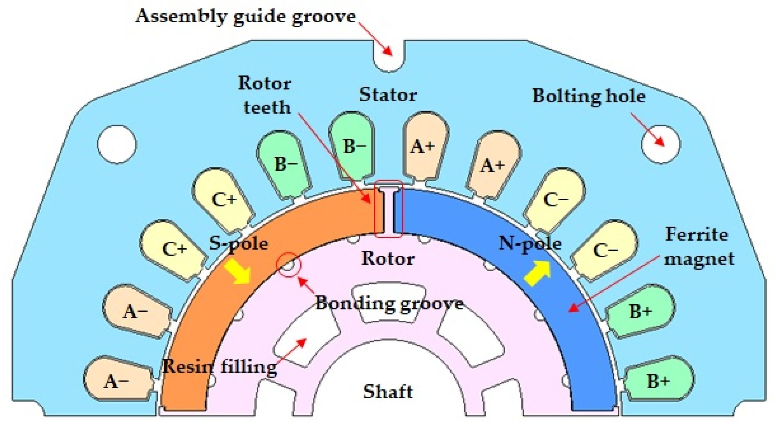
3.1. Basic Model Selection and Structural Characteristics

SPM-type PMSMs are easy to manufacture and magnetize, and have low manufacturing costs. However, there is a risk that the permanent magnet of the rotor may be scattered by centrifugal force during high-speed rotation. Recently, the operating speed range of the blower motors used in air-conditioning systems has increased, and such rotor structures may cause various problems. Therefore, in this study, the scattering of the permanent magnet was prevented by adding protrusions to the rotor structure, and the bonding force was improved by increasing the bond application area.
Figure 3 shows the cross-section (1/4 model) of the SPM-type PMSM. The image on the left in Figure 3 shows the shape before the addition of protrusions (rotor teeth), and the image on the right shows the shape after the addition of protrusions. There is a total of four rotor teeth to fix the four C-type permanent magnets before adding the protrusion to the central part of the permanent magnet. However, if an additional protrusion is installed, eight rotor teeth will exist to fix the eight C-type permanent magnets. Therefore, scattering during high-speed rotation can be prevented owing to an increase in additional protrusions. Currently, the polarity of the rotor is a total of four poles, and there is no change before or after adding the protrusion.
In the basic model with the added protrusion, the distortion of the magnetic flux density waveform increases in the air gap. Accordingly, the torque-ripple component of the motor can be increased. In this study, a protrusion addition model was used as the basic model. In addition, to overcome the disadvantages caused by the addition of protrusions, their characteristics were analyzed and optimized. In addition, by analyzing the displacement of the permanent magnet due to the bonding force during high-speed rotation and the stress received from the protrusion, it is intended to examine whether it is scattered at the rated speed.
Figure 4 shows that the bond application area increased with the addition of the protrusions. By adding a protrusion to the existing motor structure, the protrusion itself prevents the permanent magnet from scattering; however, the bonding force between the permanent magnet and rotor can be strengthened by increasing the drawing area of the bond solution. In Figure 4, the part where the bond is applied is between the permanent magnet and the rotor core, and the part expressed in brown is the area where the bond is applied. Because of the increase in the number of protrusions, the number of magnets was doubled. However, the shoe located at the end of the protrusion primarily prevents the permanent magnet from scattering. Second, it is possible to prevent scattering of the bonded permanent magnet, which increases in proportion to the applied area.
The bond application area may increase depending on the protrusion design. In addition, the bonding force increases with increasing application area. However, the shape of the protrusion causes distortion of the electro-motive force (EMF) waveform at no load. The distorted waveform eventually caused a decrease in the back electromotive force and an increase in the total harmonic distortion (THD) in the no-load state, resulting in a decrease in the power density and an increase in the torque ripple in the load state. Therefore, in this study, by optimizing the shape of the protrusion, the THD of the electromotive-force waveform was reduced during no load, and a shape that could increase the applied area while preventing a decrease in power density during load was examined.

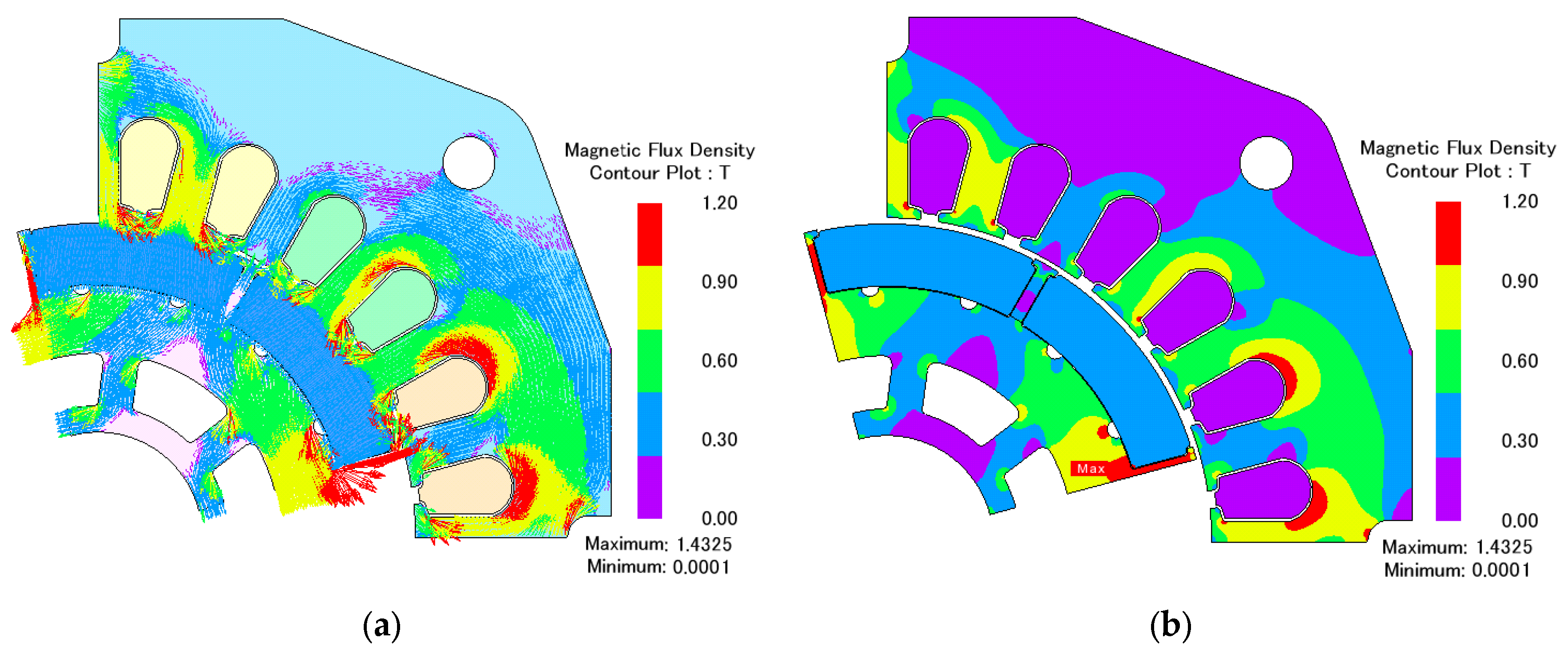
3.2. Characteristic Analysis at No Load

No-load analysis is a basic step in reviewing the winding design and permanent-magnet material selection by checking the magnitude of the counter-electromotive force in the absence of a load. To satisfy the target output, the basic model was designed to generate a counter-electromotive force of more than 33 [Vrms] of counter-electromotive force of one phase at a rated speed of 15,000 rpm. The magnetization pattern of the permanent magnet was analyzed by selecting a parallel magnetization pattern based on the manufacturing process. Figure 5 shows the phase-counter-electromotive force and cogging-torque waveforms of the basic model with added protrusions. As shown in Figure 5a, the THD of the back-EMF waveform was 38.6 [%]. This was owing to the change in the magnetic flux in the air gap caused by the addition of the protrusion. Owing to this effect, a large cogging torque was generated, as shown in Figure 5b. This represents a disadvantage of adding protrusions to increase the bonding force. This disadvantage can be overcome by optimizing the protrusion shape. Figure 6 shows the magnetic flux and magnetic flux density distributions.

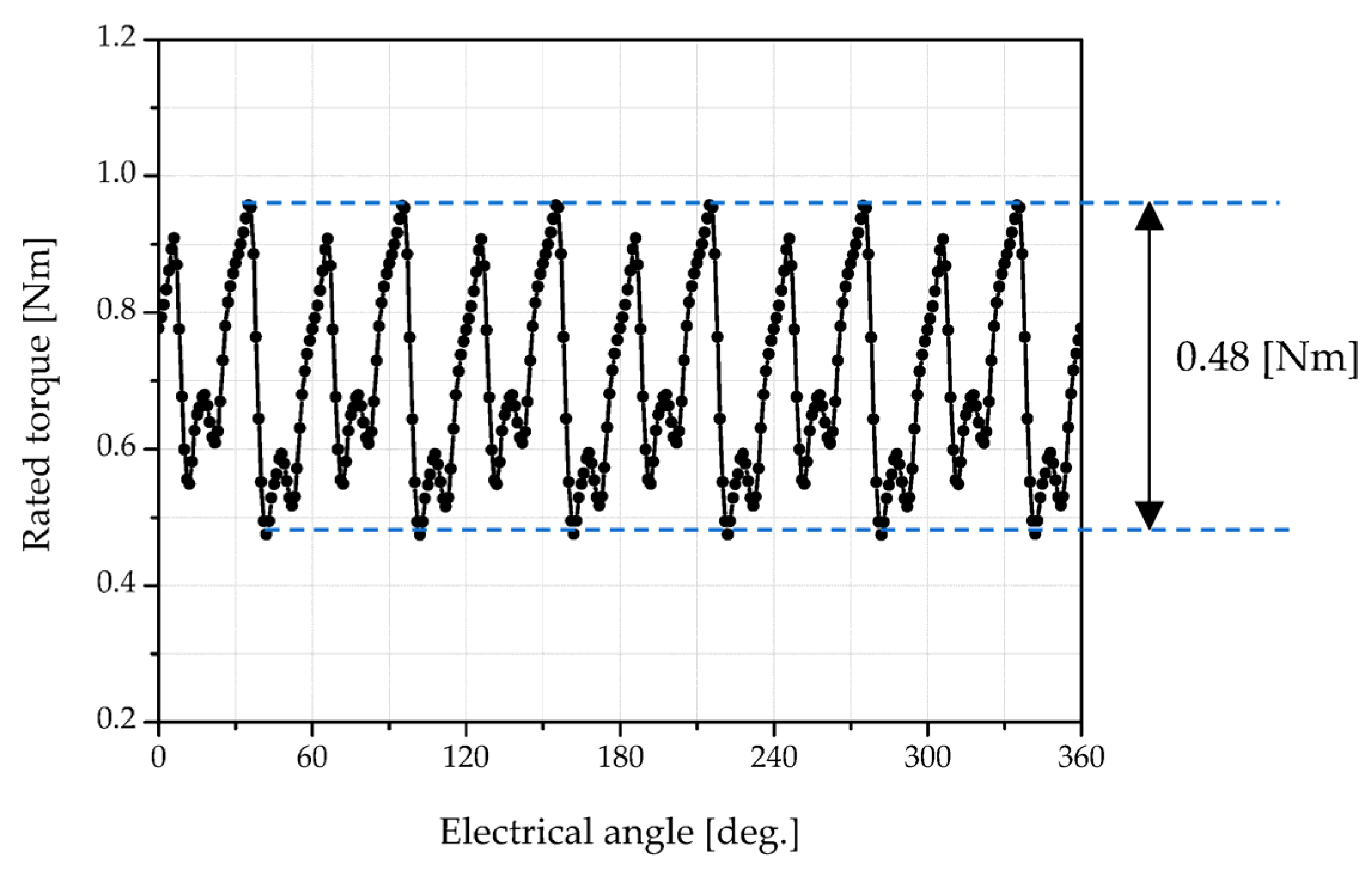
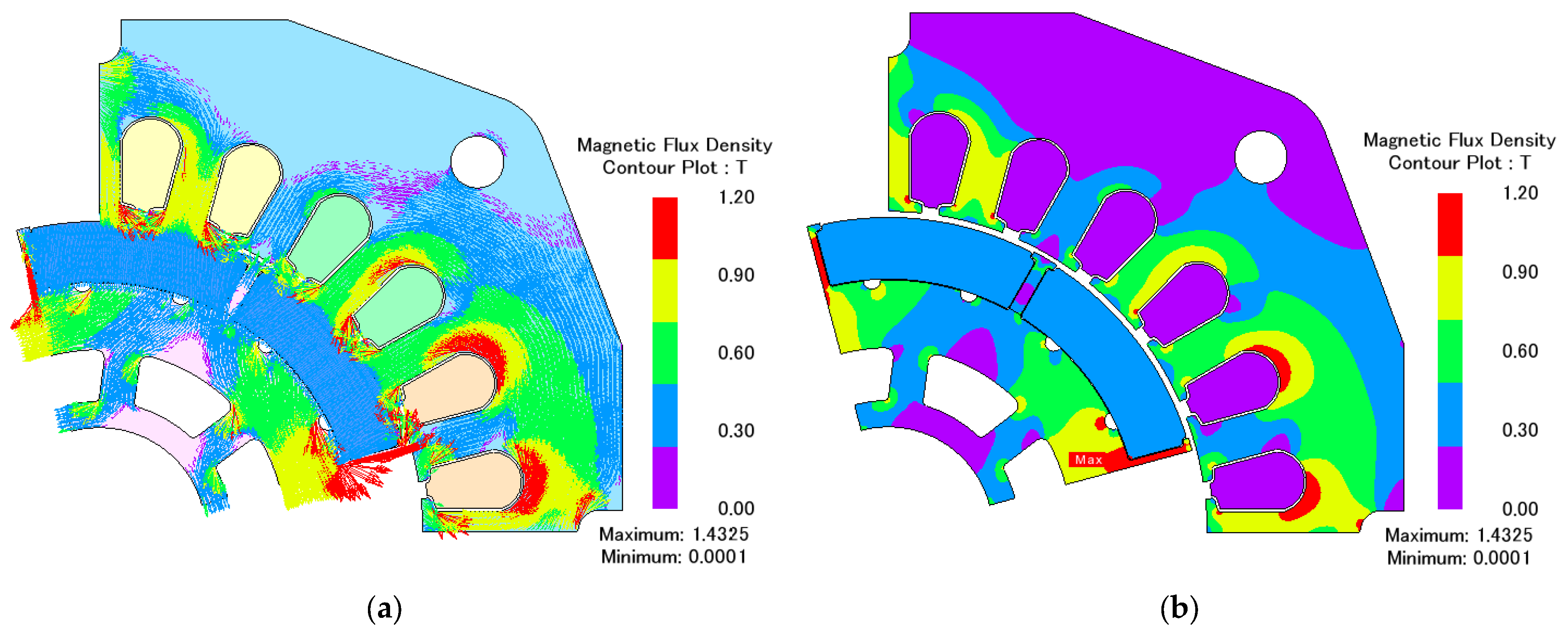
3.3. Characteristic Analysis at Rated Load

Figure 7 shows the torque waveform at the rated load. The ripple of the rated torque waveform is 0.48 [Nm] (peak-to-peak), which is very large. This is because the waveform of the load torque is affected by distortion of the EMF waveform. This torque ripple causes noise and vibrations in the motor. In addition, this may cause noise and vibrations in the structurally limited space inside a ship, which may adversely affect the ship structure. Figure 8 shows the magnetic flux and magnetic flux density distribution waveforms at the rated load. It can be observed that the magnetic flux density is saturated around the protrusion.
Table 2 presents the 2D performance analysis results for no load and rated loads. The analysis was performed using JMAG-Designer version v21. The efficiency of the basic model is 90.9 [%], and it can be seen that a very large cogging-torque ripple occurs at no load. Load analysis was performed by applying a sinusoidal current. Because the distortion rate is included in the waveform of the electromotive force generated by the terminal voltage, a large torque ripple was generated. The bonding area is the calculated area where the bond is applied between the magnet and the rotor. As the area increased, the bonding force also increased.

4. Optimization for Proposed Model

4.1. Optimization Process and Design Parameters Setting

Figure 9 shows the steps for determining the shape of the protrusion by setting and optimizing the objective function. First, the objective function and design variables were set considering the design constraints. Various experimental design methods were used within the range of the design variables. At the time of the characteristic analysis, because the structure of the basic model was a distribution area of four poles and 24 slots, only 1/4 of the analysis model was constructed, and a characteristic analysis was performed. In addition, to reduce the analysis time, asymmetry and periodic conditions were set as periodic boundary conditions. Optimization was performed using a genetic algorithm [29]. In the general specification design and optimization stage, the characteristics of various operating areas were identified through a characteristic analysis of the steady and transient states. In addition, owing to the characteristics of the air-conditioning system, the optimization was performed only at the rated speed.
Figure 10 shows the three design variables for the basic model with added protrusions. The variables considered were angle, thickness, and width of the teeth. Because these were expected to have the greatest impact on performance change, they were set as design variables. The objective function was set depending on the design variable settings, and the experimental design method for the design variables was used to analyze the change in performance according to each variable. Optimization was performed only for the rotor structure geometry to verify the effect of the additional protrusions. In addition, there are many designs in which the stator shape is fixed and only the rotor structure is changed in order to avoid redesigning the fixed part and the price merit of the conventionally used structure.

4.2. Characteristic Analysis for Setting Objective Function and Design of Experiment

A genetic algorithm was used to optimize the protrusion. A genetic algorithm (GA) is a search method that determines an optimal solution by imitating the evolution of organisms while adapting to the environment. Genetic algorithms are useful because they can theoretically determine a global optimum and can be applied to problems that are not clearly defined mathematically. Therefore, they are widely used to optimize motor structure [30,31,32,33,34,35,36,37,38,39].
Five objective functions were set to optimize the projections. As for the objective function, the bonding area (Y1, bond application area) of the magnet was basically set as the objective function. In addition, the no-load cogging torque (Y2, cogging torque at no load) and the no-load counter-electromotive force THD (Y3, THD of back EMF (phase)), which can be generated by adding protrusions and load torque ripple (Y4, torque ripple of the rated load), were set as the objective functions. Finally, the efficiency (Y5, efficiency) was set as the objective function. The constraints for each objective function are as follows.
-
Bond application area: increased by more than 10 [%] compared with the basic model;
-
Cogging torque at no load: less than 0.2 [Nm];
-
THD of back EMF at no load: 38.6 [%] or less;
-
Torque ripple at load: minimized;
-
Efficiency at load: maximum (>90.9 [%]).
A total of 15 designs of experiments cases were set for the optimization. Table 3 presents the results of the analysis for each experimental design method by using the central composite design (CCD). Based on the analysis results, a genetic algorithm was used to determine the design variable values that satisfied the objective function. Figure 11 shows the convergence process of the three-element set as design variables, and Figure 12 shows the convergence process of the objective functions. The number of iterations was set to 200 until the objective function converged and the error of the convergence value was minimized. In addition, PIAnO (PIDOTECH Inc., Seoul, Republic of Korea) was used as the genetic algorithm software [40].
Figure 13 shows that the shape of the rotor changed through optimization. Table 4 shows the dimensional changes in the basic and optimal models through optimization and Table 5 shows the convergence of the objective function. As shown in Table 4, among the design variables, the protrusion angle changed the most. Thus, it can be confirmed that the shape of the protrusion changes to a structure that prevents scattering by the magnet. In addition, through optimization, it was confirmed that the optimum model had a 12.1 [%] increase in the bond application area compared with the basic model owing to the change in the shape of the protrusion holding the magnet. Thus, it can be confirmed that a model that is more robust to scattering at high speeds was designed. In addition, it can be confirmed that the magnitude of the cogging torque at no load and torque ripple at the load converge to a point where they are significantly improved. Through a characteristic analysis of the optimization model, we verified that the objective function was improved, and compared its performance with that of the basic model.

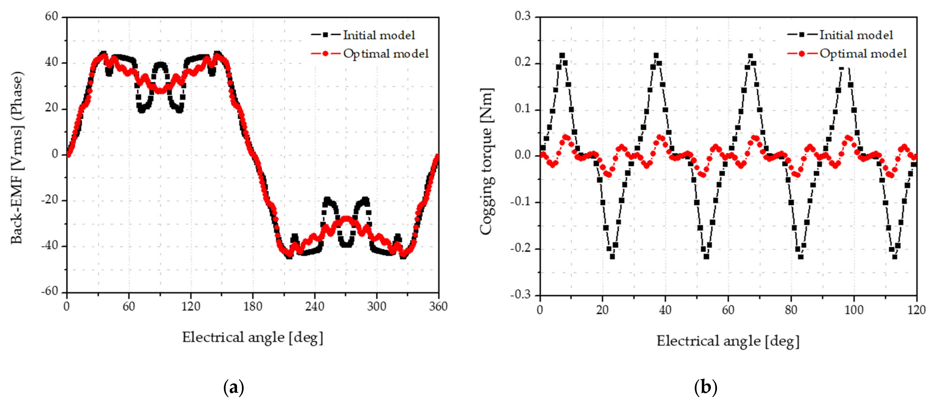
4.3. Characteristic Analysis of Optimal Model

The no-load characteristics of the optimal model were determined. Figure 14 shows the back-EMF and cogging-torque waveforms of the basic and optimal models under the no-load condition. As shown in Figure 14a, it can be confirmed that the no-load back-EMF waveform of the optimal model was improved through optimization. It can be observed that the change in the waveform generated based on an electrical angle of 90° was largely eliminated through optimization. An electrical angle of 90° was the position where the protrusions were additionally installed, and a change in the waveform of the counter-electromotive force occurred after no load was applied, according to the addition of the protrusions. However, the shape of the protrusion was changed through optimization, and the conventional waveform change was mitigated; thus, the THD of the no-load counter EMF was reduced. In addition, as shown in Figure 14b, the cogging-torque ripple decreased by 81.0 [%].
Figure 15 shows the torque waveforms and magnetic flux density distributions of the basic and optimal models under the rated load conditions. The torque ripple (peak-to-peak) of the optimal model is 0.256 [Nm], and the torque-ripple value of the basic model is reduced by −46.9 [%] compared with 0.482 [Nm]. Table 6 presents a performance comparison between the optimal and basic models. As shown in Table 6, a reduction in the cogging torque and load torque-ripple components, which were set as the objective functions of the optimization, was confirmed. This confirms the possibility of reducing the noise and vibration of the motor for the air-conditioning system inside the ship, which is the target of this study, and confirms that the efficiency is increased by 0.2 [%].

4.4. Excitation Source Analysis of Torque Ripple

Figure 16 and Table 7 show the fast Fourier transform (FFT) analysis results for the torque waveform (one cycle). Table 8 presents the results of the excitation source analysis for the model. The excitation source of the motor can be caused by various factors such as the combination of the number of poles of the rotor, number of slots of the stator, and rotational speed. In Figure 16b and Table 6, the 7th order has the largest component, except for the 1st order component. The 7th order is an excitation component generated in the 6f (1f = 500 Hz) band, and it can be confirmed that it was generated by the stator teeth.

5. Stress and Natural Vibration Mode Analysis of Rotor Structure

5.1. Stress Analysis of Rotor Structure

The stator and rotor of an electric machine have a structure in which silicon steel sheets are laminated to reduce the iron and hysteresis losses. Usually, 0.35 mm, 0.5 mm silicon steel plates are used for the lamination. When the rotor rotates at a high speed or when a large excitation force is applied to the stator winding, the stress on the rotor is destroyed and scattered. Therefore, it is necessary to review the stress characteristics of the protrusions for the optimization model at a rated speed of 15,000 rpm and to examine the changes caused by the bonding force [41,42,43,44,45]. Table 9 lists the physical properties of the electrical steel sheets used in the optimization model. As shown in the table, it is assumed that the rotor core is scattered when the stress received by the rotor exceeds 393 [Mpa]. Table 10 shows the typical properties of the bond. Based on the Loctite AA331 model, the tensile strength (at break) of the bond is 11 N/mm2. In the case of the optimized model, the permanent magnet application area per magnet is 2160.48 mm2. Assuming that at least 10 [%] of the area is bonded, 2376.53 [Mpa] is obtained. Therefore, if this value is not exceeded, it can be assumed that there is no scattering of the permanent magnets.
Figure 17 shows the rotor stress and displacement distributions generated at the rated speed of 15,000 rpm. As shown in Figure 17b, the maximum stress point of the rotor protrusion was 132.3 [Mpa], which did not exceed the yield point of the electrical steel sheet. Thus, it is assumed that there is no scattering of the rotor core owing to the change in protrusion when rotating at the rated speed. In addition, it can be confirmed that the stress margin increases up to 2.97 times when rotating at the rated speed. Also, as shown in Figure 17c), it was analyzed that the permanent magnet could have a displacement flow of 0.14 mm at the rated speed. It is judged that the load analysis reflects the displacement flow according to the existence of the gap, in which a gap of 0.1 mm is set between the permanent magnet and the rotor to consider manufacturability; therefore, a flow displacement up to 0.04 mm. The analysis results can be used for future prototype production, or when considering the maximum rotational speed limit. In addition, there is a need to review flow displacement reduction by reinforcing the bonding force or improving the protrusion shape.

5.2. Natural Vibration Mode Analysis (Stator and Case Part)

After examining the stress analysis of the rotor and the displacement analysis of the permanent magnet during high-speed rotation, the natural vibration mode between the stator and case must be reviewed. Through a natural vibration mode analysis, it is possible to determine whether there is an effect of overlapping with the frequency band at the rated speed. If an overlapping area exists, then the excitation source can be eliminated via mechanical avoidance. Figure 18 shows an assembly diagram of the motor prototype for natural vibration mode analysis. In the natural vibration mode analysis, a case and flange bracket in which bearings were inserted was constructed, and the stator was fixed inside. Figure 19 shows a cross-section of the 3D model.
Figure 20 and Table 11 present the results of the eigenmode analysis. The first component was observed at 713.9 Hz, and it was confirmed that it had a natural vibration mode in several frequency bands of each order. When the frequency band of the rotational speed and the frequency of each mode are similar, it may cause noise and vibration of the rotor. Therefore, through such an analysis, it is necessary to consider the frequency interference avoidance.
Figure 21 shows the deformation in the natural vibration mode at 713.9 Hz, which is the first component. The first component of the natural vibration mode was slightly lower because the back-yolk side of the stator was thick. Therefore, the vibration component of the motor was expected to be small. It is expected that management of the bearing assembly part will be required during high-speed operation in the future. When assembling a bearing, the tolerance or clearance of the bearing seat area must be controlled.

6. Conclusions

In this study, the general characteristics of permanent-magnet–surface-attached PMSMs used in air-conditioning and blowing systems in ships were investigated, and the analytical verification procedure and method for the high-speed scattering problem, known as the disadvantage of permanent-magnet–surface-attached PMSMs, were described. To solve the problem of scattering at high speeds, which has been identified as a disadvantage of SPM-type PMSMs, a structure for adding protrusions was proposed, and its characteristics were reviewed. Through the proposed protrusion structure, it was possible to increase the bonding drawing area by 12.1 [%] compared with the basic model. Thus, it was confirmed that the proposed structure is advantageous for accelerating the process. Additionally, through optimization, 81.0 [%] of the cogging-torque ripple and 46.9 [%] of the torque ripple were reduced. This confirms the possibility of reducing the noise and vibration problems accompanying the acceleration of an air-conditioning blower fan inside a ship structure. In addition, the rotor structure stress and permanent-magnet separation displacement analysis was performed to confirm the stress margin of the optimized rotor-structure model at the rated speed. The scattering verification method using an electromagnetic field analysis may differ from the actual method. However, using this analysis method and procedure, the time required to review the prototype was shortened, and the vibration mode trend was analyzed to improve the speed of the permanent-magnet–surface-attached PMSM. It was determined that the design reliability improved.

Author Contributions

Conceptualization, K.-Y.Y. and S.-T.L.; methodology, K.-Y.Y.; software, K.-Y.Y.; validation, K.-Y.Y. and S.-T.L.; writing—original draft preparation, K.-Y.Y.; writing—review and editing, K.-Y.Y. and S.-T.L.; and funding acquisition, S.-T.L. All authors have read and agreed to the published version of the manuscript.

Funding

This research is supported by the Korea Institute of Marine Science & Technology Promotion (KIMST) funded by the Ministry of Oceans and Fisheries, Korea (Project Name: Development of Core Equipment Technology for Electric Hybrid Propulsion Fishing Boat, Project Number: 20210369). This research was also supported by “Regional Innovation Strategy (RIS)” through the National Research Foundation of Korea (NRF) funded by the Ministry of Education (MOE) (2021RIS-002).

Institutional Review Board Statement

Not applicable.

Informed Consent Statement

Not applicable.

Data Availability Statement

The data presented in this study are available upon request from the corresponding author.

Conflicts of Interest

The authors declare no conflict of interest.

References

  1. Ajioka, Y.; Ohno, K. Electric Propulsion Systems for Ships. Hitachi Rev. 2013, 62, 231. [Google Scholar]
  2. Ma, F.; Qi, L.; Ye, S.; Chen, Y.; Xiao, H.; Li, S. Research on Fault Diagnosis Algorithm of Ship Electric Propulsion Motor. Appl. Sci. 2023, 13, 4064. [Google Scholar] [CrossRef]
  3. Yu, C.; Qi, L.; Sun, J.; Jiang, C.; Su, J.; Shu, W. Fault Diagnosis Technology for Ship Electrical Power System. Energies 2022, 15, 1287. [Google Scholar] [CrossRef]
  4. Zhang, H.; Liu, Y.; Zhao, X.; Hu, Q.; Liu, D. Fuzzy wavelet network intelligent predictive controller for vacuum injection molding. Comput. Integr. Manuf. Syst. 2010, 16, 2647–2652. [Google Scholar]
  5. Hu, Y. Model Predictive Torque Control Strategy for Marine Permanent Magnet Synchronous Propulsion Motor. Master’s Thesis, Wuhan University of Technology, Wuhan, China, 2019. [Google Scholar]
  6. Zhang, L.; Yang, M. Fault diagnosis of permanent magnet synchronous motor based on mixup-LSTM. Electr. Switch. 2022, 60, 58–62. [Google Scholar]
  7. Xue, S.; He, Q.; Pan, J.; Huang, X. Research on dynamic eccentricity fault diagnosis method of permanent magnet synchronous motor based on GA-SVM. Zuhe Jichuang Yu Zidonghua Jiagong Jishu 2022, 99–103. [Google Scholar]
  8. Sifang, Z.; Qiang, S.; Yanming, Z.; Wei, Z. Mechanical fault detection of permanent magnet synchronous motor based on improved DFA and LDA. J. Beijing Inst. Technol. 2023, 43, 61–69. [Google Scholar] [CrossRef]
  9. Niu, H.C.; Zhao, M.L.; Qin, F.Z. Study on the Ship Electric Propulsion System and Its Development. In Proceedings of the 7th International Conference on Applied Science, Engineering and Technology (ICASET 2017), Qingdao, China, 29–30 July 2017; Atlantis Press: Amsterdam, The Netherlands, 2017; pp. 212–216. [Google Scholar] [CrossRef]
  10. Jeong, C.-L.; Kim, Y.-K.; Hur, J. Optimized Design of PMSM With Hybrid-Type Permanent Magnet for Improving Performance and Reliability. IEEE Trans. Ind. Appl. 2019, 55, 4692–4701. [Google Scholar] [CrossRef]
  11. You, Y.-M.; Chung, D.-W. Optimal Design of a Permanent Magnet Synchronous Motor to Improve Torque and Demagnetization Characteristics. J. Magn. 2017, 22, 423–429. [Google Scholar] [CrossRef]
  12. Dong, J.N.; Huang, Y.K.; Jin, L.; Lin, H.Y. Comparative Study of Surface-Mounted and Interior Permanent-Magnet Motors for High-Speed Applications. IEEE Trans. Appl. Supercond. 2016, 26, 1–4. [Google Scholar] [CrossRef]
  13. Hong, J.; Wang, S.; Yang, Z. Comparison of electromagnetic excited vibration for SPM and IPM motors. In Proceedings of the 2017 19th European Conference on Power Electronics and Applications (EPE’17 ECCE Europe), Warsaw, Poland, 11–14 September 2017; pp. 1–8. [Google Scholar] [CrossRef]
  14. Pellegrino, G.; Vagati, A.; Guglielmi, P.; Boazzo, B. Performance Comparison Between Surface-Mounted and Interior PM Motor Drives for Electric Vehicle Application. IEEE Trans. Ind. Electron. 2012, 59, 803–811. [Google Scholar] [CrossRef] [Green Version]
  15. Ahn, J.H.; Han, C.; Kim, C.W.; Choi, J.Y. Rotor Design of High-Speed Permanent Magnet Synchronous Motors Considering Rotor Magnet and Sleeve Materials. IEEE Trans. Appl. Supercond. 2018, 28, 1–4. [Google Scholar] [CrossRef]
  16. Chu, G.; Dutta, R.; Rahman, M.F.; Lovatt, H.; Sarlioglu, B. Analytical Calculation of Maximum Mechanical Stress on the Rotor of Interior Permanent-Magnet Synchronous Machines. IEEE Trans. Ind. Appl. 2020, 56, 1321–1331. [Google Scholar] [CrossRef]
  17. Du, G.; Xu, W.; Zhu, J.; Huang, N. Rotor Stress Analysis for High-Speed Permanent Magnet Machines Considering Assembly Gap and Temperature Gradient. IEEE Trans. Energy Convers. 2019, 34, 2276–2285. [Google Scholar] [CrossRef]
  18. Li, W.; Qiu, H.; Zhang, X.; Cao, J.; Zhang, S.; Yi, R. Influence of Rotor-Sleeve Electromagnetic Characteristics on High Speed Permanent-Magnet Generator. IEEE Trans. Ind. Electron. 2014, 61, 3030–3037. [Google Scholar] [CrossRef]
  19. Yang, Y.; Castano, S.M.; Yang, R.; Kasprzak, M.; Bilgin, B.; Sathyan, A.; Dadkhah, H.; Emadi, A. Design and Comparison of Interior Permanent Magnet Motor Topologies for Traction Applications. IEEE Trans. Transp. Electrif. 2017, 3, 86–97. [Google Scholar] [CrossRef]
  20. Kim, B.-C.; Lee, J.-H.; Kang, D.-W. A Study on the Effect of Eddy Current Loss and Demagnetization Characteristics of Magnet Division. IEEE Trans. Appl. Supercond. 2020, 30, 1–5. [Google Scholar] [CrossRef]
  21. Fengge, Z.; Guanghui, D.; Tianyu, W.; Guangwei, L. Review on Development and Design of High Speed Machines. Trans. Chin. Electrotech. Soc. 2016, 31, 1–18. [Google Scholar]
  22. Liu, G.; Liu, M.; Zhang, Y.; Wang, H.; Gerada, C. High-Speed Permanent Magnet Synchronous Motor Iron Loss Calculation Method Considering Multiphysics Factors. IEEE Trans. Ind. Electron. 2020, 67, 5360–5368. [Google Scholar] [CrossRef]
  23. Zhang, Y.; McLoone, S.; Cao, W.; Qiu, F.; Gerada, C. Power Loss and Thermal Analysis of a MW High-Speed Permanent Magnet Synchronous Machine. IEEE Trans. Energy Convers. 2017, 32, 1468–1478. [Google Scholar] [CrossRef] [Green Version]
  24. Du, G.; Huang, N.; He, H.; Lei, G.; Zhu, J. Parameter Design for a High-Speed Permanent Magnet Machine Under Multiphysics Constraints. IEEE Trans. Energy Convers. 2020, 35, 2025–2035. [Google Scholar] [CrossRef]
  25. Fang, H.; Li, D.; Qu, R.; Li, J.; Wang, C.; Song, B. Rotor Design and Eddy-Current Loss Suppression for High-Speed Machines With a Solid-PM Rotor. IEEE Trans. Ind. Appl. 2019, 55, 448–457. [Google Scholar] [CrossRef]
  26. Qi, Z.; Zhang, Y.; Yu, S.; Xu, Z. Design and Analysis of a 30 kW, 30,000 r/min High-Speed Permanent Magnet Motor for Compressor Application. Energies 2022, 15, 3923. [Google Scholar] [CrossRef]
  27. Qin, X.-F.; Shen, J.-X. Multi-Physics Design of High-Speed Large-Power Permanent Magnet Synchronous Motor. In Proceedings of the 2020 Fifteenth International Conference on Ecological Vehicles and Renewable Energies (EVER), Monte Carlo, Monaco, 10–12 September 2020; pp. 1–5. [Google Scholar] [CrossRef]
  28. Kirtley, J.L.; Banerjee, A.; Englebretson, S. Motors for Ship Propulsion. Proc. IEEE 2015, 103, 2320–2332. [Google Scholar] [CrossRef]
  29. Deb, K. A fast and elitist multiobjective genetic algorithm: NSGA-II. IEEE Trans. Evol. Comput. 2002, 6, 182–197. [Google Scholar] [CrossRef] [Green Version]
  30. Ohnishi, T.; Takahashi, N. Optimal design of efficient IPM motor using finite element method. IEEE Trans. Magn. 2000, 36, 3537–3539. [Google Scholar] [CrossRef] [Green Version]
  31. Rahman, M.M.; Kim, K.-T.; Hur, J. Design and Optimization of Neodymium-Free SPOKE-Type Motor with Segmented Wing-Shaped PM. IEEE Trans. Magn. 2014, 50, 865–868. [Google Scholar] [CrossRef]
  32. Parasiliti, F.; Villani, M.; Lucidi, S.; Rinaldi, F. Finite-Element-Based Multiobjective Design Optimization Procedure of Interior Permanent Magnet Synchronous Motors for Wide Constant-Power Region Operation. IEEE Trans. Ind. Electron. 2012, 59, 2503–2514. [Google Scholar] [CrossRef]
  33. You, Y.-M.; Yoon, K.-Y. Multi-Objective Optimization of Permanent Magnet Synchronous Motor for Electric Vehicle Considering Demagnetization. Appl. Sci. 2021, 11, 2159. [Google Scholar] [CrossRef]
  34. Yoon, K.Y.; Hwang, K.Y. Optimal Design of Spoke-Type IPM Motor Allowing Irreversible Demagnetization to Minimize PM Weight. IEEE Access 2021, 9, 65721–65729. [Google Scholar] [CrossRef]
  35. Hwang, K.Y.; Jo, J.H.; Kwon, B.I. A Study on Optimal Pole Design of Spoke-Type IPMSM With Concentrated Winding for Reducing the Torque Ripple by Experiment Design Method. IEEE Trans. Magn. 2009, 45, 4712–4715. [Google Scholar] [CrossRef]
  36. Yoon, K.; Kwon, B. Optimal Design of a New Interior Permanent Magnet Model Using a Flared-Shape Arrangement of Ferrite Magnets. IEEE Trans. Magn. 2016, 52, 1–4. [Google Scholar] [CrossRef]
  37. Song, T.; Zhang, Z.; Liu, H.; Hu, W. Multi-objective optimisation design and performance comparison of permanent magnet synchronous motor for EVs based on FEA. IET Electr. Power Appl. 2019, 13, 1157–1166. [Google Scholar] [CrossRef]
  38. Hong, G.; Wei, T.; Ding, X. Multi-objective Optimal Design of Permanent Magnet Synchronous Motor for High Efficiency and High Dynamic Performance. IEEE Access 2018, 6, 23568–23581. [Google Scholar] [CrossRef]
  39. Zhao, W.; Wang, X.; Gerada, C.; Zhang, H.; Liu, C.; Wang, Y. Multi-Physics and Multi-Objective Optimization of a High Speed PMSM for High Performance Applications. IEEE Trans. Magn. 2018, 54, 1–5. [Google Scholar] [CrossRef]
  40. PIDOTECH Inc. PIAnO User ’s Manuals and Tutorials; PIDOTECH Inc.: Seoul, Republic of Korea, 2019. [Google Scholar]
  41. Mallin, L.R.; Barrans, S.M. A Review of the High-speed Permanent Magnet Rotor Stress Analysis used for Automotive Air-handling Machines. Eur. J. Eng. Technol. Res. 2020, 5, 448–456. [Google Scholar] [CrossRef]
  42. Zhao, N.; Liu, W. Loss Calculation and Thermal Analysis of Surface-Mounted PM Motor and Interior PM Motor. IEEE Trans. Magn. 2015, 51, 1–4. [Google Scholar] [CrossRef]
  43. Pu, T.; Du, G.; Tong, J.; Huang, N.; Li, N.; Xu, W. Comparison of Rotor Strength of Various Rotor Structures for Ultra-high speed Permanent Magnet Synchronous Motor. In Proceedings of the 2021 IEEE 4th Student Conference on Electric Machines and Systems (SCEMS), Huzhou, China, 1–3 December 2021; pp. 1–6. [Google Scholar] [CrossRef]
  44. Shao, Y.; Wang, X.; Gao, Q.; Li, Y. Rotor Strength Analysis of Ultra-High Speed Permanent Magnet synchronous Motor. In Proceedings of the 2019 22nd International Conference on Electrical Machines and Systems (ICEMS), Harbin, China, 11–14 August 2019; pp. 1–4. [Google Scholar] [CrossRef]
  45. Xie, Y.; Xia, Y.; Li, Z.; Li, F. Analysis of Modal and Vibration Reduction of an Interior Permanent Magnet Synchronous Motor. Energies 2019, 12, 3427. [Google Scholar] [CrossRef] [Green Version]
Figure 1. Structure of SPM-type PMSM for air-conditioning and blowing system (1/2 model).
Energies 16 05486 g001
Figure 2. General design process.
Energies 16 05486 g002
Figure 3. Structure of permanent-magnet–surface-mounted PMSM motor (1/4 model).
Energies 16 05486 g003
Figure 4. Bond application area between ferrite magnet and rotor core.
Energies 16 05486 g004
Figure 5. Analysis result at no load: (a) back-EMF waveform and (b) cogging-torque waveform.
Energies 16 05486 g005
Figure 6. Analysis result at no load: (a) magnetic flux diagram and (b) magnetic flux density distribution at no load.
Energies 16 05486 g006
Figure 7. Torque waveform at rated load (at 15,000 rpm).
Energies 16 05486 g007
Figure 8. Analysis result at rated load: (a) magnetic flux diagram and (b) magnetic flux density distribution at rated load.
Energies 16 05486 g008
Figure 9. Design process of PMSM of air-conditioning and blowing systems for ships.
Energies 16 05486 g009
Figure 10. Structure of permanent-magnet–surface-mounted PMSM motor (1/2 model).
Energies 16 05486 g010
Figure 11. Convergence of design variables: (a) X1, width; X2, thickness; and (b) X3, angle.
Energies 16 05486 g011
Figure 12. Convergence of the objective function: (a) Y1, bond application area; (b) Y2, cogging torque; Y4, torque ripple of rated load; and (c) Y3, THD of back EMF; Y5, efficiency.
Energies 16 05486 g012aEnergies 16 05486 g012b
Figure 13. Shape change through optimization: (a) basic model and (b) optimal model.
Energies 16 05486 g013
Figure 14. Performance comparison at no load: (a) back EMF and (b) cogging torque.
Energies 16 05486 g014
Figure 15. Performance comparison at rated load: (a) torque and (b) magnetic flux density distribution.
Energies 16 05486 g015
Figure 16. Torque-ripple waveform and THD analysis at rated load: (a) rated torque and (b) FFT of rated torque waveform.
Energies 16 05486 g016
Figure 17. Rotor stress and displacement distribution generated at 15,000 rpm: (a) fixed condition for rotor stress analysis (attachment of bonding between rotor and permanent magnet); (b) rotor stress distribution (maximum 132.3 [Mpa] stress occurs on protrusions); and (c) rotor displacement distribution (permanent-magnet part 0.14 mm displacement occurs).
Energies 16 05486 g017
Figure 18. Natural vibration analysis 3D modeling configuration.
Energies 16 05486 g018
Figure 19. Sectional view of 3D modeling.
Energies 16 05486 g019
Figure 20. Eigenmode assay results.
Energies 16 05486 g020
Figure 21. Eigenmode analysis result (714 Hz): (a) eigenvector plot and (b) eigencontour plot.
Energies 16 05486 g021
Table 1. Specifications of basic model.
ItemUnitBasic SPM Model
Stator slot/Rotor pole24/4
Output power (10 % margin consideration)W1100
Rated speedrpm15,000
Air gapmm0.7
StatorInner diameter/Stackmm73.0/50.0
Material35PN270
RotorOuter diameter/Stackmm71.6/50.0
Materialmm35PN270
MagnetOuter, inner diameter/Magnet thicknessmm71.6, 57.6/7.0
Material/Grade/MakerFerrite/9BE/Hitachi metals
WindingDiameter/Turns/Number of parallel circuitsΦ1.1/20 turns/four parallel
MaterialCopper
Table 2. Characteristics of the basic SPM-type PMSM.
ItemUnitBasic SPM model
No
load
Back EMFVrms33.4
THD%38.6
Cogging-torque rippleNm0.43
Rated
load
Rated speedrpm15,000
Rated torqueAverageNm0.70
Ripple (peak-to-peak)Nm0.48
Current (Phase)Arms23.8
Output powerW1098.7
LossCopperW40.5
IronW69.7
Efficiency%90.9
Bond areamm315,426.3
Table 3. Simulation results of central composite design.
No.x1x2x3Y1Y2Y3Y4Y5
11.41.16.815,687.8 0.38 41.9 0.52 90.5
20.91.55.015,667.7 0.43 39.1 0.49 90.8
30.60.813.916,817.0 0.18 35.4 0.27 91.1
41.01.728.218,077.2 0.24 39.6 0.38 90.4
51.40.715.716,703.9 0.18 45.8 0.37 90.1
60.61.810.416,390.4 0.21 37.7 0.36 91.0
70.72.022.917,650.6 0.18 37.7 0.44 90.8
81.51.624.617,534.8 0.21 46.9 0.56 89.6
90.90.517.017,059.5 0.16 38.7 0.33 90.9
100.81.025.617,954.8 0.22 36.8 0.44 90.8
111.21.912.116,335.7 0.17 45.9 0.33 89.9
121.10.68.616,027.5 0.31 43.2 0.51 90.4
131.11.317.516,983.1 0.11 42.5 0.31 90.4
140.51.419.317,403.4 0.04 34.4 0.27 91.1
151.30.924.217,617.5 0.18 43.2 0.52 90.3
Table 4. Optimal points of the design variables.
Design VariablesUnitBasic ModelOptimal ModelDifference
Widthmm1.50.5−1.0
Thicknessmm0.771.40+0.63
Angledeg.4.7818.20+13.42
Table 5. Objective function of the objective function.
Objective FunctionUnitBasic ModelOptimal ModelDifference
Y1 (Bond application area)mm215,426.317,283.8+12.1 [%]
Y2 (Cogging torque)Nm0.4300.076−82.3 [%]
Y3 (THD of back EMF)%38.634.4−4.19
Y4 (Torque ripple)Nm0.4800.261−45.6 [%]
Y5 (Efficiency)%90.991.1+0.22
Table 6. Optimal design results.
ItemUnitBasic
Model
Optimal
Model
Difference
No loadBack EMFVrms33.432.8−1.8 [%]
THD%38.634.5−4.1 [%]
Cogging-torque rippleNm0.430.08−81.0 [%]
Rated loadRated speedrpm15,00015,000
TorqueAverageNm0.700.70
RippleNm0.482 (69.0 [%])0.256 (36.7 [%])−46.9 [%]
Current (Phase)Arms23.823.8
Output powerW1098.71,098.3
LossCopperW40.640.6
IronW69.766.1−5.2 [%]
Efficiency%90.991.1+0.2 [%]
Table 7. Distortion analysis of torque waveform.
Mode123456789
Frequency05001k1.5k2.0k2.5k3.0k3.5k4.0k
Magnitude0.699300.00065800.0003100.05398600
Table 8. Analysis of causes of electromagnetic and mechanical forces.
OrderStator
Tooth
Rotor
Pole
Mechanical
Rotation Freq.
Electrical
Rotating Freq.
Cogging
Torque
Torque
Ripple
24.0 X4.0 X1.0 X2.0 X24.0 X12.0 X
12.0 f2.0 f0.5 f1.0 f12.0 f6.0 f
1st6000 Hz1000 Hz250 Hz500 Hz6000 Hz3000 Hz
Table 9. Mechanical properties of electrical steel.
JS StandardThickness [mm]Tensile Strength [N/mm2]Yield point [MPa]
35PN2300.35535393
Table 10. Typical properties of the bond.
MakerGradeTensile Strength at Break [N/mm2]Bond Application
Area per Magnet [mm2]
Yield Point
[Mpa] (min)
LOCTITE331112160.482376.5
Table 11. Eigenmode analysis results.
Mode123456789
Frequency [Hz]713.9815.0820.71573.31576.01636.42278.43716.23719.5
Disclaimer/Publisher’s Note: The statements, opinions and data contained in all publications are solely those of the individual author(s) and contributor(s) and not of MDPI and/or the editor(s). MDPI and/or the editor(s) disclaim responsibility for any injury to people or property resulting from any ideas, methods, instructions or products referred to in the content.

