Abstract
In modern power systems, interharmonics have emerged as noninteger frequency components that appear in current or voltage signals. Double-stage AC-DC-AC converters have been identified as a primary source of interharmonics. Previous studies have highlighted modulation techniques, filters, passive components, unbalanced conditions and DC link effects as relevant factors. However, the interaction between these factors and the inertial properties of induction motors has not been explored. This study assesses various types of AC drives, including variable frequency drives (VFDs) and soft starters (AC choppers), to investigate their interaction with machine inertial properties in interharmonic generation. The employed technique for time-frequency spectral analysis is the wavelet synchrosqueezed transform combined with a clustering method. This paper demonstrates that the interaction of the inertial properties of low-power induction motors with the variations of the switching frequencies of the VFDs, the filters used in the DC link and a soft start indirectly contribute to harmonic generation and potentially to interharmonics in the electrical grid and the outputs of the inverter.
1. Introduction
The constant growth and integration of modern power systems along with developments in renewable energy areas have led to an increase in distortions in voltage and current waveforms. These distortions, known as interharmonics, consist of nonmultiple components of the fundamental frequency and result in a degradation of power quality (PQ) in future electrical networks [1,2]. Consequently, there is a need to update the applicable limits [3]. Interharmonics mainly originate from nonperiodic changes in current and voltage caused by loads operating in nonsteady states and/or amplitude modulation in control strategies [4]. Several factors contribute to their generation, including the use of nonlinear loads, double conversion systems, cascaded subsynchronous converters [5,6], asymmetric induction motors and the incorporation of AC/DC and DC/AC conversions in renewable energy sources such as photovoltaic systems [7,8,9] and wind turbines [10,11]. Additionally, double-stage systems, which consist of two AC systems operating at different frequencies interconnected through a DC link [12,13], have also been identified as significant sources of interharmonics. Notable devices include IGBT-based voltage source inverters (VSIs) used in static compensators (STATCOMs) and HVDC applications [14,15], as well as cycloconverters, electric arc furnaces and power communication lines [16,17,18].
Interharmonics have adverse effects that include distortions and energy losses, leading to equipment heating, mechanical system oscillations, acoustic disturbances and interference with power communication lines [19]. One prominent effect is the flicker effect, characterized by visible changes in light intensity in LED and fluorescent lamps [20]. This effect is caused by variations in voltage magnitude and has a direct correlation with interharmonics and voltage fluctuations [21,22].
Induction motors and AC drives play an essential role in the industry, facilitating motion exchange in industrial processes [23]. However, PQ assessments have demonstrated that electrical disturbances, such as voltage imbalance and harmonic distortion, reduce power and torque performance, impacting the operation of motors and other equipment [24,25].
Several negative effects of these disturbances on electrical machines have been reported. For instance, voltage fluctuations in induction motors can lead to saturation in the magnetic circuit [26] and increased ohmic losses within the rotor and stator windings, resulting in overheating [27] and a clear reduction in efficiency [28,29]. The presence of subharmonics and interharmonics in voltage causes speed fluctuations, leading to excessive torsional vibrations [30,31] and torque pulsations that coincide with the natural frequency of the first elastic mode. This can result in the destruction of the powertrain due to torsional resonance in medium- and high-power motors [32,33].
The relationship between induction motors and AC drives [34] can generate disturbances in the electrical grid, establishing a direct connection between motors and drives in terms of PQ [35].
AC choppers, which are control systems for AC machines based on thyristors (SCR) used for soft starting, regulate the voltage supply during machine startup, reducing startup currents [36,37,38]. However, a decrease in torque is observed since it is proportional to the square of the current. This topology has been suggested to generate significant levels of interharmonic distortion [39]. Soft starters and amplifiers have been identified as sources of harmonics with resonances and nonstationary characteristics [40,41].
On the other hand, variable frequency drives (VFDs) are commonly used in industrial applications for energy savings and the control of multiple machines compared to soft starters, leading to increased utilization of these devices. However, VFDs are also one of the main sources of interharmonic distortions [42,43]. VFDs consist of a double AC-DC-AC conversion stage that includes a large capacitor in the link to store energy. Subsequently, a pulse width modulation (PWM) inverter converts the DC link voltage into an adjustable variable frequency and magnitude three-phase AC voltage to control the motor speed. However, perfect filtering is never achieved [44] and interharmonic distortion can pass between the two AC systems. Under balanced conditions, VFDs may exhibit poor performance [45].
Modulation techniques can influence the interharmonics of current at the input of the VFD. The appropriate selection of the switching frequency of the drive depends on the power level of the VFD system [46,47,48]. Small capacitors in the DC link can have a long lifespan, although they cannot store energy and can lead to interharmonic distortions. Studies have shown that front-end rectifiers based on electronic inductors (EI) reduce low-frequency oscillations originating from the load side. Additionally, conventional filters with AC- and/or DC-side chokes, as well as DC-link capacitors, cannot be used to mitigate interharmonic distortions [49]. It has been documented that in special cases, such as when the inverter is in overmodulation or when the load is unbalanced [34], interharmonics of current can be expected in supply systems. The magnitudes, frequencies and phase sequence of these interharmonics can vary depending on the operating conditions of the motor [43,50], imbalances in currents, supply voltage (including switching angles) and fluctuating mechanical loads, among other factors [45,49,51,52,53,54]. Different load values and torque oscillations can also contribute to the generation of interharmonics.
If the torque load is considered constant while the inverter operates in the linear modulation region, the amplitudes of interharmonic currents are minimal under ideal conditions [53]. However, AC motors driven by a VFD generate acoustic noise and mechanical vibrations [55]. Excessive torsional vibrations are particularly notable due to the interaction of the natural frequency of the machines (). If the control method of the inverter is not properly adjusted, these vibrations can cause torque pulsation multiplication in high-power induction motors, locomotives, drilling rigs and large drives in turbomachinery applications [32,56,57,58,59,60]. When the VFD operates with open-loop control, it has been demonstrated that the amplitude and frequency of the interharmonics depend on the in a motor-mechanical system due to the currents generated in the stator and rotor [61,62].
Previous works have not considered the inertial properties of the load and the machine in the generation of interharmonics in the grid and low-power induction motors driven by different AC drive topologies, such as VFDs and soft starters. It has only been confirmed that drive input current distortions are larger at lower load torque values [45].
However, it has been demonstrated that the inertia properties of the machine and the load do influence the generation of undesired disturbances, including torque pulsations, currents and vibrations, especially in the positive sequence, under the influence of interharmonic and subharmonic voltage effects in induction motors [32,33,63,64]. In this scenario, a load with a negligible moment of inertia (NMI) that is lower than the motor’s moment of inertia generates larger disturbances [33]. This suggests that, when starting motors driven by soft starters and VFDs, significant interharmonics can be generated in the grid and inverter output.
Therefore, the objective of this study is to demonstrate how the generation of interharmonics in the input current and output voltages of VFDs is indirectly influenced by the inertial properties of low-power induction motors. The present investigation is supported by simulation results considering DC link filter designs in VFDs and it is further validated through experiments with soft starters and VFDs operating at different switching frequencies. These findings contribute to the expansion of research in PQ regarding interharmonics, AC drives and their close relationship with induction motors, with the goal of ensuring optimal performance and efficiency in grid-connected equipment and machines.
2. Theoretical Background
2.1. AC Chopper or Soft Starter on Induction Motor
AC choppers are based on thyristors (SCR) and during startup, they reduce the current and temporarily the voltage. In the off state, they do not produce purely sinusoidal waveforms. In three-phase loads, transients occur and the combination of phases can limit acceleration torque jumps while increasing currents [36,37]. Figure 1 shows the different phase controls used, behaving similarly to TRIACs (antiparallel thyristors).
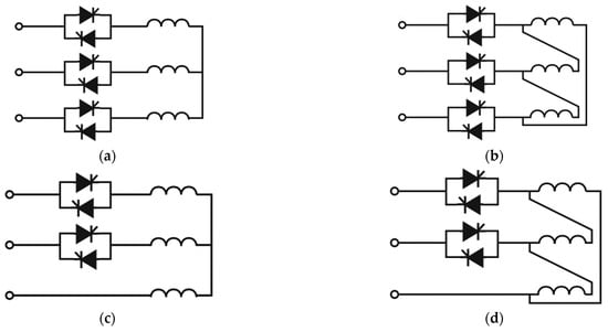
Figure 1.
Phase control by AC choppers. (a) Three-phase control; (b) three-phase control fully connected. (c) Biphasic phase control; (d) biphasic phase fully connected.
The representation consists of the electrical time constants based on the simplified equivalent circuit of the induction motor; the rotor is depicted with a sinusoidal rotor electromotive force (emf) . In Figure 2a, the induction motor is fed by a soft starter. The control is based on the phase angle , the delay angle or the extinction angle and the control introduces dynamic issues, the latter being measured with respect to the voltage zero crossings. In Figure 2b, it is assumed for a pure reactance and a source , where the total reactance is the total leakage reactance, , thus the machine can be represented with an additional reactance, , proportional to .
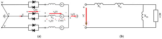
Figure 2.
Phase control of a three-phase induction machine with the direction of the voltage from () to (). (a) Induction machine fed by an AC chopper; (b) approximate circuit for an induction machine.
Angles and are defined by the zero crossing of , therefore the following relationships hold:
where is the phase displacement with respect to , which is π/2 with respect to , thus:
2.2. Interharmonics on Variable Speed Drives
The system is considered bidirectional and consists of a three-phase diode rectifier, a DC link and space vector pulse width modulation (SVPWM) three-phase inverter, typically composed of six switching elements, which supply power to a three-phase motor. Depending on the equivalent DC load impedance, the output DC current of the converter contains ripple components. Therefore, the current is transferred from the DC side to the AC side, generating currents in the power supply. This topology is shown in Figure 3. The DC link can introduce interharmonics both on the grid side and the motor side through the rectifier and the inverter.
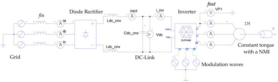
Figure 3.
Representation of a variable frequency drive for system analysis.
From the concept of VFDs, the topology of the second and twelfth harmonics of the inverter current in the DC link causes interharmonics when reflected on the AC side of the rectifier. The frequency of these interharmonic currents is given by [34]:
where is the interharmonic frequency, is the order of the harmonic current on the DC link and inverter side, is the operating frequency of the inverter, is the frequency on the grid side.
Considering the operation of the inverter, depending also on the selected modulation technique, pulsating voltage waveforms are generated at the inverter terminals. The inverter-switched output voltage waveforms contain a DC offset, a fundamental component, and baseband harmonics, , (simple harmonics of the fundamental output frequency), carrier harmonics, , and sideband harmonics. The equation is usually represented in the literature as a double Fourier integral analysis of a two-level pulse-width-modulated waveform [44,49,65]:
where corresponds to the DC offset component of the PWM waveform and and represent the carrier index variable (carrier harmonics) and baseband index variable, which define the (angular) frequency of each harmonic component of the switched phase leg output voltage as . The fundamental and carrier angular frequencies are denoted as and ; these frequencies will not be an integer ratio and the train of switched pulses created by the phase leg will not be periodic.
For the groups of harmonics for = 0, the frequencies are defined only for and = 0 and the harmonic frequencies are only defined by ; therefore, these groups are called baseband and carrier harmonic components. In this case, for any value of and , the magnitudes generated for all the harmonic components defined in the waveform of the phase-switched output of the inverter can be evaluated. For the final double summation in Equation (7) m, n = 0 is the set of all possible frequencies, which are the combinations of the modulating carrier waveform harmonics and the reference waveform, known as sideband harmonics and existing as groups around the carrier harmonic frequencies [65].
, , and denote the harmonic coefficients or magnitudes of the harmonic components, which should be obtained according to the associated modulation methods applied on the inverter. The parameter will take values of 0, 1 and 1 for the output phases for , and . The output voltages with harmonic content that feed the induction motor under balanced conditions give rise to the three-phase output (x = u, v, w); their respective representation in the frequency domain is calculated using their load phase impedance () [44]:
where , and are switching functions of the inverter, is the DC link voltage and, if the inverter operates as a lossless system, the contribution of the output side currents (, and ) to the DC-link inverter side current can be obtained as:
The theory states that the supply side current is the modulated DC link current, which can be described by the following equation:
The generation of interharmonics on the grid side is caused by current oscillations on the rectifier side of the DC link, resulting from the switching operation of the inverter. These oscillations will be multiplied by the well-known switching functions of the six-pulse diode rectifier:
where , , are the switching functions that describe the operation of the diode converter bridge, denotes the fundamental period of the grid voltage and is the frequency. The DC side current contains waveforms that are modeled as:
where , is the peak magnitude of the sinusoidal components and is the ripple frequency on the DC side. If we consider the case where there is only one ripple component in the DC current:
In general, the frequencies of the interharmonics produced by a VFD are:
where represents the pulses of the rectifier and represents those of the inverter. If the interharmonic components coincide with the resonance frequency of the system, they can be amplified [49,51,52] depending on the sign of the expression. Their sequence is the same as that of the harmonic components of the power system being modulated [50]. The oscillations of the DC link generated by the operation of the inverter are divided in the DC link according to , where and are the currents leaving the DC terminal of the rectifier and flowing through the DC link capacitor. The amplification of the DC link current oscillation, as it transitions from the inverter side to the rectifier side, will affect the current harmonics on the inverter side of the DC link due to the resonance factor of the DC link. This can be determined using a resonance factor (RF):
2.3. Torsional Analysis
The torsional analysis consists of an electromechanical system of two inertias, defined as the torsional or natural frequency of the first elastic mode given by [32,56]:
where is the inertia of the motor, is the inertia of the coupled load and is the equivalent torsional stiffness; it is divided by 2π to convert the value to Hertz.
There are torsional vibrations when the motor is started by the VFDs [56,58], which is considered as a dependence on the natural frequency of induction motors, especially in high-power motors [32]. The relationship between the effects of voltage interharmonics and the inertial properties of machines have an inherent relationship with the interaction of a motor-mechanical system, which in turn influences the electrical signals generated in the stator and rotor, such as currents with interharmonics that can give rise to vibrations and torque pulsations [33,62]. The study assumes that the motor operates at a constant torque NMI, that is, a load with a lower moment of inertia compared to the machine.
2.4. Time-Frequency Analysis Based on Wavelet Synchrosqueezing Transform and Clustering Method
There are several methods for the estimation of stationary and time-varying harmonics and interharmonics [66]. The wavelet synchrosqueezed transform (SSWT) is a time-frequency (TF) analysis method that has proven to be effective in analyzing nonstationary signals, even in signals with closely spaced frequency components [67,68,69]. It is useful for analyzing multicomponent signals with oscillating modes. A general expression for this type of signal with summed components (amplitude-modulated and frequency-modulated) is:
where is the varying amplitude and is the instantaneous phase. The SSWT is a time-frequency method that reassigns the energy of the signal in frequency and is calculated based on the continuous wavelet transform (CWT) [70]:
This reassignment compensates for the propagation effects caused by the mother wavelet, as the energy is reassigned only in the frequency direction, preserving the time resolution of the signal. The method has been combined with unsupervised machine learning techniques called clustering, such as k-means [69,71]. In this approach, the frequencies extracted from the ridges are precisely localized in the time-frequency domain, assuming they form tight clusters for normal data, while different data points are located far away from their nearest neighbors. The clustering method used in the analysis is density-based spatial clustering of applications with noise (DBSCAN), which recognizes groups based on the density of points within each group, which is considerably higher than outside of those groups [72,73]. Data points with low density are considered as noise.
3. Methodology
To validate the hypothesis, preliminary results were obtained using a simulation in PSIM 9.1.1, as shown in Figure 3. The simulation involved a VFD and considered two cases: (1) an induction motor with a constant torque mechanical load having higher inertia compared to the machine’s moment of inertia and (2) an induction motor with a constant torque mechanical load and a negligible moment of inertia (NMI) of J = 0 [33].
The parameters of the VFDs were based on a conventional DC filter (CNV) and a small DC link capacitor (SDLC) [44] as these are common topologies used in this type of AC drive; they are listed in Table 1. The simulations utilized the SVPWM modulation technique, known for its lower ripple current and reduced harmonic generation characteristics [74,75]. This method considers the interaction of the inverter’s output phases and optimizes the harmonic content of the three-phase induction motor [45,46,48].

Table 1.
Parameters of the VFD system in PSIM.
This part of the study focuses on the interactions of VFDs in low-power induction motors with different moments of inertia, specifically under ideal supply conditions and leakage inductances in the grid as the dominant factor, which will affect the performance of the units. It is important to note that the presence of nonideal supply conditions can complicate the identification of sources without complex analysis.
The experiments conducted in this research are presented for two induction motors with similar rated characteristics under 1 kW. Their basic parameters are listed in Table 2. In Figure 4a shows the motor 1 manufactured by ABB, with an inertia moment of J = 0.01 , is coupled to a Gerogi Kobold DC generator and a Baldor tachometer. On the other hand, in Figure 4b, motor 2, manufactured by Siemens, is decoupled and unloaded in torque with an inertia moment of J = 0.0048 .
Table 2.
Parameters of the induction motors.
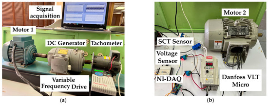
Figure 4.
Motors with VFDs (a) coupled induction motor with DC Generator; (b) uncoupled induction motor with sensors for measurements.
The soft starters were implemented to detect interharmonic currents generated in the grid during the startup. One of the devices corresponds to a SIEMENS 3RW3028-1bb14, using a biphasic phase control and an Allen Bradley SMC-3 soft starter, which has a three-phase control.
The VFDs used are a Danfoss VLT Micro Series 176F7302, Allen Bradley Powerflex 523-A and General Electric AF-60 LP Micro Drive, all of them with similar parameters of 1.5 kW and 2.0 HP at 200–240 V and 60 Hz. The modulation technique used in all three VFDs is based on PWM sinusoidal modulation. However, each VFD operates at a different switching frequency: 3 kHz for the Danfoss (DF) VFD, 4 kHz for the Allen Bradley (AB) VFD and 5 kHz for the General Electric (GE) VFD. Investigations performed on motor 1 and motor 2 with soft starters and VFDs were with open loop control.
For the experiments in this paper, the voltages of one of the phases to ground each motor were measured using a ZMPT101B voltage sensor previously calibrated with a Keithley DMM6500 multimeter. The input current measurements in the VFDs were made using an SCT-013-000 non-invasive AC current sensor, which has been widely used in the analysis of electrical current signals in photovoltaic systems and induction motors [76,77,78] and they were also previously calibrated. The signal acquisition was performed using a National Instruments DAQ-6009 with Labview 2021 software. The sampling rate for the acquired signals was 10.504 kHz and a low-pass third-order antialiasing Butterworth filter with a cutoff frequency of 3 kHz was applied.
Based on IEC 61000-4-7 [79,80], the nominal values of subharmonic and interharmonic currents and voltages were obtained using the discrete Fourier transform (DFT) with a time window width (Tw) of 200 milliseconds in simulations. On the other hand, the DFT often suffers from spectral leakage and the picket fence effect, mainly due to errors in the synchronization of the fundamental frequency and harmonics. Therefore, a DFT with a Hanning window of 1 s was exclusively implemented only in the experiments.
However, the use of a DFT instrument does not exclude the application of other analysis principles such as the Wavelet. To avoid aliasing and suppress the noise from the generated harmonics and interharmonics, the SSWT was employed with the MatlabTM 2019 software. The bump wavelet factor was used for the TF analysis of interharmonics. The inverse of the synchrosqueezing algorithm was applied for precise signal reconstruction and identification of prominent components. In addition, the DBSCAN clustering technique was implemented to detect the most relevant frequencies of the extracted ridges in the signal reconstruction.
4. Results
4.1. Preliminary Results
In the analysis, CNV-1 is established for an induction motor with a load having a higher moment of inertia than the motor, while CNV-2 has a load inertia equivalent to NMI [33]. This same sequence is repeated for SDLC-1 and SDLC-2.
In Figure 5, the resonance factor (RF) value between 24–60 Hz is higher when there is an NMI in the load at lower frequencies, in this case for CNV-2 and SDLC-2. This means that at frequencies around 24 to 40 Hz, the oscillations in the DC link could affect the harmonics generated at the inverter output. At 30 Hz a second harmonic and a zero sequence in is generated.
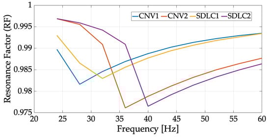
Figure 5.
Resonance factor for CNV and SDLC cases.
Therefore, it is suggested that the interharmonics generated at the VFD input and inverter output exhibit oscillations in a range of values close to approximately 30 Hz. In the case of a 60 Hz grid, this could correspond to the second harmonic, particularly in motors with a load having an NMI. Such conditions can significantly degrade the PQ at the input and affect the damping in the DC link filter. In the case of SDLC, the resonance frequency of the VFD input impedance increases at higher frequencies [44,48], which depends on the reactance values in the line.
Figure 6 demonstrates a behavior similar to the resonance factor. It is important to note that for conventional filters in the DC link, the highest interharmonic current value of 6 Amps is reached at 24 Hz for CNV-2. However, for CNV-1, when the moment of inertia of the load is greater than that of the motor, it does not have a significant effect on the generation of interharmonics. Beyond 36 Hz in both CNV-1 and CNV-2, the interharmonic current decreases and remains constant. On the other hand, for the configuration with a small capacitor in the DC link, there is a noticeable difference between SDLC-1 and SDLC-2 from 28 to 40 Hz, with SDLC-2 exhibiting higher interharmonic current generation in the grid. However, up to 40 Hz, the SDLC filter achieves a significant reduction in interharmonics compared to the CNV filter. The interaction of the motor with an NMI load and the VFD, for both the CNV and SDLC filters, still results in a considerable amount of current interharmonics being transferred to the grid.
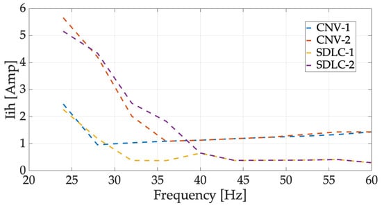
Figure 6.
Computed rated current interharmonics largest amplitude on grid side vs. frequency of VFD from 24 to 60 Hz.
The interharmonic currents generated at the output of the inverter that feed the induction motor are shown in Figure 7. In this case, the CNV filters exhibit better performance compared to the SDLC filters; however, CNV-2 shows the highest interharmonic current, reaching 2 Amps at 26 Hz. For the SDLC filters, they fail to reduce current interharmonics in the motor. SDLC-1 reaches a maximum value of 3.7 Amps at 28 Hz, but from this frequency up to 40 Hz, SDLC-2 has a significant impact. Beyond 40 Hz, all the filters exhibit similar values of interharmonic currents. As a result, the motor current increases to maintain the desired load level, leading to higher current consumption from the source and an increase in the fundamental current [43].
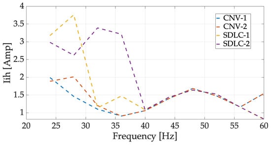
Figure 7.
Computed rated current interharmonics largest amplitude on induction motor vs. frequency of VFD from 24 to 60 Hz.
Figure 8 demonstrates the consistency of the voltage subharmonics generated in the induction motor, showing the same behavior in the presence of NMI; only at 24 Hz, did both CNV-1 and SDLC-1 cases reach the maximum values of subharmonic voltages. However, from 28 to 36 Hz, both CNV-2 and SDLC-2 filters exhibit a similar behavior. Therefore, it is suggested that the generation of voltage interharmonics from the inverter output is higher when a motor and a mechanical load with an NMI are present at frequencies close to 30 Hz. At 40 Hz, all four topologies exhibit matching characteristics.
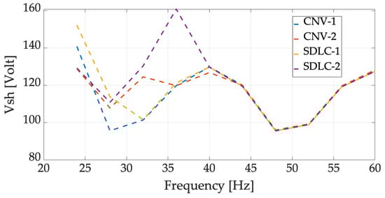
Figure 8.
Computed rated voltage subharmonics largest amplitude on induction motor vs. frequency of VFD from 24 to 60 Hz.
In Figure 9, the voltage interharmonics at the inverter output exhibit oscillations before 40 Hz for both types of CNV and SDLC filtering are shown. It can be observed that at 24 Hz, SDLC-1 reaches a maximum value of 16.4 Volts, while at 32 Hz, SDLC-2 exhibits a higher generation of voltage interharmonics compared to other filter configurations in the DC link. This behavior is attributed to the use of a small capacitor in the DC link, which leads to similar characteristics in interharmonic currents generated at the output of the inverter when a motor interacts with a load with an NMI. At 40 Hz, all filter topologies coincide in the maximum value of interharmonic voltage, which is 18.4 Volts.
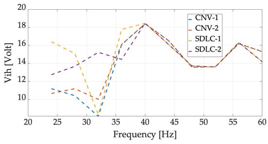
Figure 9.
Computed rated voltage interharmonics largest amplitude on induction motor vs. frequency of VFD from 24 to 60 Hz.
4.2. Interharmonics Generated by Soft Starter
The experiments conducted with soft starters demonstrate behavior in the currents generated during the starting process, which is dependent on the load torque. These currents contain interharmonic content that is introduced into the grid. The biphasic control was adjusted with a voltage value of 40% for the start, where this percentage determines the starting torque. Therefore, it is possible to achieve a lower starting current, resulting in a soft start. The ramp-up time to reach the rated speed was set to 15 s. Figure 10 depicts the currents generated on the grid side for motor 1.
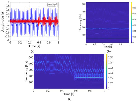
Figure 10.
Biphasic control by soft starter on motor 1. (a) Measured current signal on grid side; (b) TF spectrogram of original signal. (c) TF spectrogram of signal reconstructed.
In Figure 10a, the reconstructed signal for the fourth extracted ridge is shown, while in (b), the appearance of two interharmonics between the first and third harmonics at 100.23 Hz and 140.18 Hz can be observed, with variations around 179.29 Hz over time. The spectrogram in (c) reveals suboscillations around the fifth harmonic, confirming the significant magnitude of the current interharmonics.
Motor 2, as shown in Figure 11a, exhibits a behavior with more variations in magnitude and time. Significant magnitudes in Figure 11b are observed at 93.72 Hz, 100.23 Hz and 140.18 Hz. In Figure 11c, the spectrogram corresponds to the third extracted peak from the original signal. There is no presence of interharmonics beyond the fifth harmonic compared to motor 1. However, there is a significant presence of interharmonics between the first and third harmonics. The distorted voltages and currents in motor 2, compared to motor 1, introduce interharmonics that could negate the reduction of the fundamental harmonics. Thus, the impact of a load with an NMI on interharmonics can be confirmed.
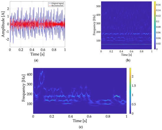
Figure 11.
Biphasic control by soft starter on motor 2. (a) Measured current signal on grid side; (b) TF spectrogram of original signal. (c) TF spectrogram of signal reconstructed.
In the case of full-phase control for both motors, the startup time was set to 10 s, with an initial torque of 15% and no rotation changes. Figure 12 illustrates the current signal for the motor: (a) shows a short time period signal generation under nonstationary conditions, resulting in harmonics occurring only at the first and after the fifth harmonic, accompanied by nonrelevant interharmonics around these frequencies in (b). However, in (c), the significant generation of interharmonics is observed on motor 2, primarily with multiple components between the first and third harmonics at 102.5 and 167.65 Hz; (d) displays the corresponding signal reconstruction, highlighting significant components with notable oscillations. This emphasizes the importance of inertial load and indicates that soft starters, as an AC drive, could generate interharmonics during the startup of low-power induction motors.
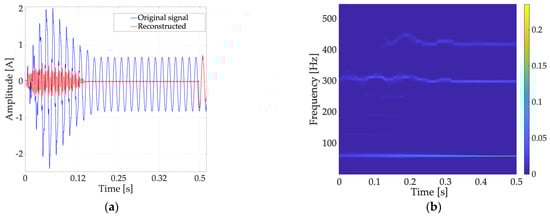
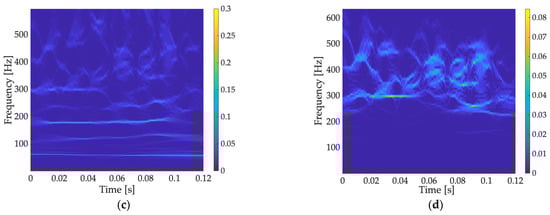
Figure 12.
Full phase control by soft starter on both induction motors. (a) Measured current signal on motor 1; (b) TF spectrogram of original signal on motor 1; (c) TF spectrogram of original signal on motor 2; (d) TF spectrogram of signal reconstructed on motor 2.
Depending on the inertia of the load, transient oscillations occur in the current during the starting process. This relationship can be confirmed by configuring the VFD as a soft starter, which leads to reduced current during startup, corresponding to the change in natural torque frequency [28].
4.3. Voltage Interharmonics on Induction Motors Generated by VFDs
In the experiments focused on the VFD, the sinusoidal PWM modulation can introduce additional harmonics and subsequent interharmonics in the output of the inverter. These resonances and distortions may have a negative impact on the effects of interharmonics, particularly in terms of vibrations [30,33]. Taking into consideration the factors involved in these circumstances, Figure 13a illustrates the subharmonic voltages generated by the AB VFD for both motors. Motor 2, without a torque load attached, exhibits slightly higher subharmonic generation than motor 1 in the frequency range of 1–30 Hz. Furthermore, in Figure 13b, the generation of interharmonic voltages is higher in motor 2 at frequencies from 1 to 24 Hz. However, at 29 Hz, the interharmonic voltage in motor 1 becomes significant at 19.4 Volts, as does motor 2 at 43 Hz with similar values. Therefore, a similar response to the inertial load analyzed in previous works for low- and medium-power motors can be considered [30,31,33].
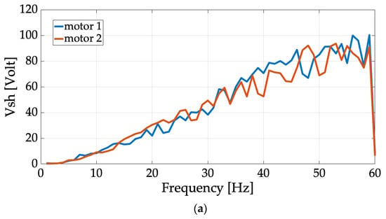
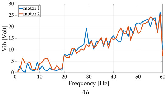
Figure 13.
Measured rated voltages on both motors vs. frequency of VFD Allen Bradley from 1 to 60 Hz; (a) largest voltage subharmonics amplitude; (b) largest voltage interharmonics amplitude.
Figure 14 also confirms the presence of oscillations in motor 1 at 128.19 and 131.09 Hz as well as around the third harmonic. On the other hand, motor 2 does not exhibit negative effects due to these variations. It is noteworthy that even though there are no variations in the magnitude of the interharmonics, the dominant interharmonic voltage is 19.6 Volts for motor 2 compared to 13.5 Volts for motor 1. The AB VFD operates at a switching frequency of 4 kHz and thus, when operating in the frequency range of 1 to 24 Hz, the interharmonics at the output of the inverter have a significant impact on low-power induction motors with a load NMI. Conversely, at frequencies close to 30 Hz, which correspond to the second harmonic generated at the inverter output, the interharmonic generation has an impact on motors with characteristics like motor 1. Beyond 40 Hz, the dominant voltage interharmonics are observed in motors without coupled loads (motor 2).
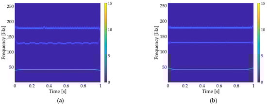
Figure 14.
TF voltage spectrogram at 43 Hz by VFD Allen Bradley; (a) TF spectrogram of motor 1; (b) TF spectrogram of motor 2.
In Figure 15a, the Danfoss VFD demonstrates that with a switching frequency of 3 kHz, the voltage subharmonics on motor 2 are higher in the frequency range of 1 to 5 Hz, while no significant variations are observed from 5 to 60 Hz for both motors. However, in Figure 15b, a significant interharmonic difference is observed between motor 1 and motor 2, particularly at certain frequencies within the anticipated range of 1–22 Hz. At 30 Hz, motor 2 exhibits the highest interharmonic voltage of 93.9 Volts, unlike the values observed at frequencies of 23–27 Hz for motor 1.
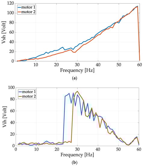
Figure 15.
Measured rated voltages on both motors vs. frequency of VFD Danfoss VLT Micro from 1 to 60 Hz; (a) largest voltage subharmonics amplitude; (b) largest voltage interharmonics amplitude.
The spectrograms reveal an interesting effect. In Figure 16a, the presence of the fourth and eighth harmonics accompanied by interharmonic oscillations is evident. The magnitude at 78.37 Hz is significantly greater than the fundamental frequency of the grid. In Figure 16b, a peculiar effect is observed with two interharmonics around 78 Hz and 131 Hz, which can be detrimental to the machine, while the frequency with the highest magnitude corresponds to the third harmonic.
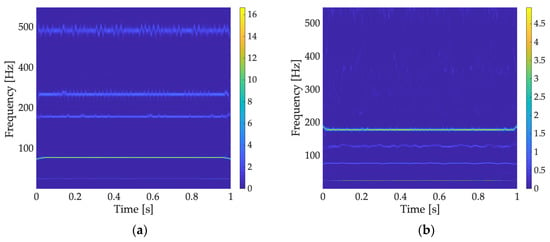
Figure 16.
TF voltage spectrogram at 26 Hz by VFD Danfoss VLT Micro; (a) TF spectrogram of motor 1; (b) TF spectrogram of motor 2.
In Figure 17a, the effect is reversed at 26 Hz of the VFD. When operating at 32 Hz, motor 1 generates only one interharmonic between the first and third harmonics. On the contrary, in Figure 17b, motor 2 exhibits interharmonics close to the fifth and eighth harmonics, with an interharmonic magnitude of 14 Volts at 95 Hz, which is much higher than that observed for motor 1, which is only a few volts.
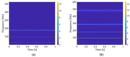
Figure 17.
TF voltage spectrogram at 32 Hz by VFD Danfoss VLT Micro; (a) TF spectrogram of motor 1; (b) TF spectrogram of motor 2.
Therefore, when a VFD operates at low switching frequencies, the impact of voltage interharmonic generation on the inverter outputs during the operation of an induction motor becomes significant. This impact is even more pronounced for motors with decoupled loads or loads that possess lower inertial properties compared to the machine itself.
For the General Electric VFD operating at a switching frequency of 5 kHz, notable differences can be observed in the generation of voltage subharmonics between motor 1 and motor 2, as shown in Figure 18a. Additionally, there are variations in the magnitudes of voltage interharmonics at the inverter output for both motors, as depicted in Figure 18b. It is worth noting that at frequencies close to 30 Hz, where the General Electric VFD operates, the magnitudes of interharmonics are significantly lower compared to the other VFDs. Furthermore, at frequencies ranging from 16 to 20 Hz, the magnitudes are higher in motor 2, while the highest interharmonic occurs in motor 1 at 23.6 Volts.
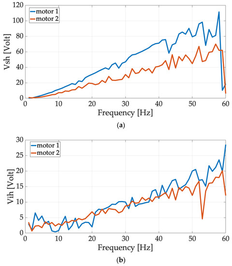
Figure 18.
Measured rated voltages on both motors vs. frequency of VFD General Electric AF-60 LP Micro Drive from 1 to 60 Hz; (a) largest voltage subharmonics amplitude; (b) largest voltage interharmonics amplitude.
Moreover, in Figure 19, the spectrograms reveal interesting patterns when the VFD operates within the frequency range of 50 to 60 Hz. In Figure 19a, motor 1 exhibits oscillations primarily near the third harmonic. Meanwhile, in Figure 19b, significant oscillations occur in the interharmonic components near the fundamental frequency, third harmonic and fifth harmonic at 62.66, 67.01, 163.9, 167.7 and 175.3 Hz.
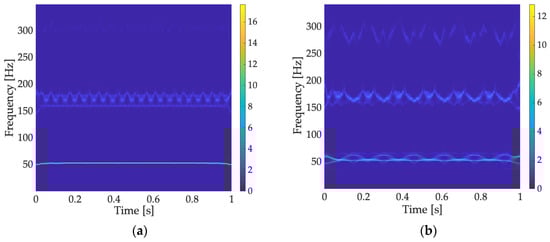
Figure 19.
TF voltage spectrogram at 53 Hz by VFD General Electric AF-60 LP Micro Drive; (a) TF spectrogram of motor 1; (b) TF spectrogram of motor 2.
4.4. Input Current Interharmonics Generated by ADS
The interharmonic currents generated in the induction motor, as seen in Figure 20, exhibit higher levels at low switching frequencies (3 kHz) for both motor 1 and motor 2 from 1 to 32 Hz. Among the VFDs analyzed, the AB VFD demonstrates better performance in mitigating interharmonic generation. However, beyond 40 Hz, interharmonic generation becomes significant for both AB and GE VFDs. This behavior is associated with the nominal currents generated in each motor when operating at frequencies close to 60 Hz, as well as the dynamic response considering the inertial load characteristics.
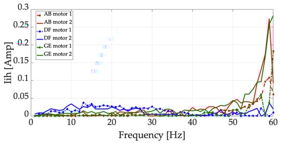
Figure 20.
Measured rated current interharmonics largest amplitude on both motors vs. frequency of VFDs from 1 to 60 Hz.
The analysis in time and frequency of these components at the current input of the VFDs reveals changes in the magnitudes of the harmonic and interharmonic components that oscillate around them. Figure 21 illustrates differences in the magnitudes of harmonics at the operating frequency of 29 Hz for the AB VFD. Notably, in (a), the third harmonic of motor 1 is almost insignificant, whereas in (b) from Figure 21, motor 2 exhibits a slightly higher presence of the third harmonic. Additionally, the magnitudes of the fifth and seventh harmonics are smaller in motor 2 compared to motor 1. For the DF VFD operating at 32 Hz, the presence of a third harmonic in the current is observed in both motors. In Figure 22a, motor 1 exhibits greater magnitudes of the third harmonic, whereas in (b), oscillations around the odd harmonics are noticeable in motor 2. Figure 23 depicts a similar effect observed in the motors operating at 53 Hz, specifically with the GE VFD, which has the highest switching frequency (5 kHz) in this study. Motor 1 exhibits odd harmonics with greater magnitude and noticeable oscillations.
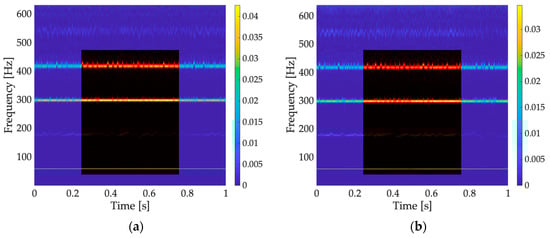
Figure 21.
Spectrogram of the current grid at 29 Hz using a VFD Allen Bradley, displaying significant harmonics and interharmonics represented by red to yellow hues, with the identified regions enclosed in a black box; (a) TF spectrogram of motor 1; (b) TF spectrogram of motor 2.
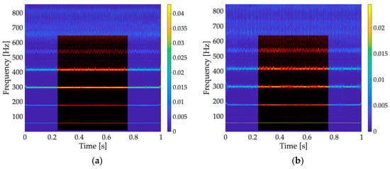
Figure 22.
Spectrogram of the current grid at 32 Hz using a VFD Danfoss VLT Micro, displaying significant harmonics and interharmonics represented by red to yellow hues, with the identified regions enclosed in a black box; (a) TF spectrogram of motor 1; (b) TF spectrogram of motor 2.
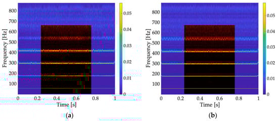
Figure 23.
Spectrogram of the current grid at 53 Hz using a VFD General Electric AF-60 LP Micro Drive, displaying significant harmonics and interharmonics represented by red to yellow hues, with the identified regions enclosed in a black box; (a) TF spectrogram of motor 1; (b) TF spectrogram of motor 2.
4.5. Interharmonic Mitigation Strategies in AC Drives
The generation of interharmonics depends on the type of AC drive used for the starting and operation of induction motors; therefore, the various factors involved that can magnify these disturbances must be considered. Among the known strategies for harmonic mitigation, the use of passive filters stands out; however, they are only recommended for mitigating specific harmonic frequencies. Selecting an appropriate interharmonic mitigation technique requires several considerations.
The use of soft starters and VFDs can lead to electromagnetic interference (EMI) issues, which is why the use of series smoothing inductive filters on the power grid side could ensure protection during the inverter switching stage, mitigate voltage imbalances during soft starter startups and extend the lifespan of capacitors in the DC link of VFDs. However, an inappropriate value of the smoothing inductors could generate harmonic resonances in the grid, especially if it is a grid with significant capacitance [40].
When considering the use of soft starters, the voltage percentage and start time duration must be properly configured to reach the motor’s rated speed, considering its inertia properties, as well as the number of rotor and stator slots and their skew angle, in order to minimize this problem [38]. Experimental research shows that biphasic soft starters have a significant impact on the generation of interharmonic currents, especially in motors with a low moment of inertia (NMI). Therefore, it is advisable to opt for the use of three-phase soft starters and consider an appropriate configuration in the startup parameters. Table 3 provides a summary of the findings.
Table 3.
Interharmonic generation by soft starters.
Low-power induction motors operating with VFDs in open-loop Volts-Hertz (V/f) control at low switching frequencies result in considerable interharmonic generation, especially in the case of a low moment of inertia (NMI). Table 4 shows the most significant magnitudes and frequencies observed in the conducted experiments.
Table 4.
Generation of interharmonics by VFD with PWM sinusoidal modulation.
Configuring an appropriate switching frequency would reduce interharmonic generation in induction motors. Additionally, to mitigate disturbances in the DC link and load-side oscillations, the use of modern electronic inductor filters (EI) should be considered [49], considering that the SVPWM modulation technique can reduce interharmonic amplitudes when operating at high switching frequencies [44,46,48].
However, the effect of interharmonics is inherently related to the harmonics of electromagnetic torque and their amplitude and frequency depend on the natural frequency of the motor-mechanical system (). From a torsional analysis perspective, interharmonic effects result in vibrations [30,33]. If the system is sufficiently dampened in low-power induction motors, especially those with coupled loads, resonant vibrations can be avoided [62]. It should be noted that, unlike high-power motors, the for small or low-power machines is typically only tens of hertz, while for larger machines it may be a few hertz [32].
A viable and affordable alternative to mitigate interharmonic generation in a VFD-driven mechanical system, based on torsional analysis, is the use of closed-loop control (with sensors) of speed or torque (current) in a cascade arrangement, considering the motor design data, particularly its moment of inertia [58]. Predicting torsional vibration generated by interharmonics and optimizing the control system (speed control) before motor startup through a frequency and torsional stability analysis to mitigate vibrations, based on intersections with the machine’s natural frequency, is an important approach [61].
Depending on the type of AC drive, the inertial properties of the induction motor and its coupled load, various alternative methods can be considered to mitigate interharmonic generation depending on PQ requirements and available budget. In many cases, affordable solutions can be achieved since most VFDs have available configurations for closed-loop control functions.
5. Discussion
This study is limited to the analysis of interharmonic currents and voltages. It is worth noting that the inertial properties of the machine and its load can amplify these disturbances, as the motor is sensitive to changes in speed and load [30,33,63]. It is important to acknowledge the factors and phenomena that contribute to the generation of interharmonics between machines and power electronic devices used in their operation. The moment of inertia of a low-power motor is not a direct cause of interharmonics but the inertial load serves as a relevant indirect factor [32,53,56,62,63]. Even a small moment of inertia, lower than the inertia moment of the machine, can influence the generation of disturbances in the motor and the electrical network, highlighting the close relationship between inertial parameters and the interaction of frequency converters for PQ [35].
The power electronic devices used in AC drives, such as fast-switching transistors, introduce harmonics in voltage and current waveforms, along with electromagnetic interactions and electrical resonances, which can lead to the generation of interharmonics [36]. The consideration of starting/driving an induction motor using a VFD or a soft starter has an important influence on the contribution of interharmonics within the grid and the motors. The utilization of a soft starter with various start configurations in the motor phases substantiated the significant interaction between current initialization and torque. This interaction results in interharmonic generation in the grid and motor windings, particularly in unloaded motors [39,40,41]. Additionally, it is noteworthy to consider the rotational speed and rapid load variations of the machine.
Specifically, for VFDs, incorrect modulation and control strategies, or the absence of proper filters, are considered contributing factors [42,45,48]. It is relevant to mention that even with a modulation technique designed to reduce the generation of harmonics, such as SVPWM (space vector pulse width modulation), oscillations can be observed when considering an inertial load with an NMI, regardless of the filtering topology in the VFD’s DC link.
The interharmonic voltages generated at the inverter output are influenced by the load characteristics in low-power motors [30,32]. When using a modulation technique such as sinusoidal PWM, as opposed to SVPWM, it becomes particularly apparent that at low-frequency switching, the interharmonic magnitudes will be higher, approaching the values at which the VFD operates, such as 30 Hz for a 60 Hz system or 25 Hz for a 50 Hz system. This is due to the presence of , the second harmonic at the inverter output, or the zero sequence . It is important to consider that the generation of interharmonics depends on multiple factors and is not limited solely to the moment of inertia of the motor, although it may indirectly contribute to them.
Recognizing the factors associated with induction motors and AC drives can aid in the development of strategies to mitigate interharmonic effects in motors with lower moments of inertia and drives operating at low switching frequencies. This may involve integrating new filter system designs, developing advanced control algorithms or implementing preventative measures. Identifying the causes and factors that indirectly contribute to these disturbances in PQ contributes to the improvement of standards and regulations [33,35].
6. Conclusions
The presented research emphasizes the significance of interharmonic generation in induction motors operated by various devices, including soft starters (AC choppers) and VFDs. It has been demonstrated that the interaction between the inertial properties of the motor load and other factors indirectly contributes to the generation of voltage and current interharmonics. This phenomenon is particularly notable during soft starting, which involves a significant ramp-up time to reach the rated speed and at the inverter output of VFDs operating at low switching frequencies.
The complexity of this phenomenon can vary due to several factors, including the drive configuration or topology, modulation technique of the VFD and characteristics of the induction motor and its properties. While the moment of inertia of the machine itself is not a direct cause, it is a decisive factor when combined with the coupled inertial load, influencing the dynamic response to load or frequency changes [33,53,62,63]. Therefore, the motor’s condition under disturbances can be closely linked to the electrical system, reflecting the generation of interharmonics [46,51].
It is important to note that the generation of interharmonics is a multifactorial phenomenon. In addition to the moment of inertia of the motor and its inertial load, other elements of the electrical system, such as the presence of nonlinear loads and the impedance of transmission lines and control devices, can also influence the generation of adverse effects in both the machine and the electrical network.
Author Contributions
Conceptualization, A.G.-O. and J.J.-C.; methodology, A.G.-O., J.J.-C. and J.E.M.-S.; software, A.G.-O. and R.O.-O.; validation, A.G.-O. and J.J.-C.; investigation, A.G.-O.; data curation, R.O.-O.; writing—original draft preparation, A.G.-O. and R.O.-O.; visualization, J.E.M.-S. and R.O.-O.; supervision, A.G.-O.; All authors have read and agreed to the published version of the manuscript.
Funding
This research received no external funding.
Data Availability Statement
The data presented in this study are available on request from the corresponding author.
Conflicts of Interest
The authors declare no conflict of interest.
References
- Yang, J.; Wang, T.; Wang, Z. Analysis of subsynchronous oscillation propagation characteristics caused by interharmonics in wind integrated power system. In Proceedings of the 2019 IEEE Power Energy Society General Meeting (PESGM), Atlanta, GA, USA, 4–8 August 2019; pp. 1–5. [Google Scholar]
- Zhang, X.P.; Yan, Z. Energy quality: A definition. IEEE Open Access J. Power Energy 2020, 7, 430–440. [Google Scholar] [CrossRef]
- Drapela, J.; Halpin, M.; Langella, R.; Meyer, J.; Mueller, D.; Sharma, H.; Testa, A.; Watson, N.R.; Zech, D. Issues and challenges related to interharmonic distortion limits. In Proceedings of the 2020 19th International Conference on Harmonics and Quality of Power (ICHQP), Dubai, United Arab Emirates, 6–7 July 2020; pp. 1–6. [Google Scholar]
- Testa, A.; Akram, M.F.; Burch, R.; Carpinelli, G.; Chang, G.; Dinavahi, V.; Xu, W. Interharmonics: Theory and modeling. IEEE Trans. Power Deliv. 2007, 22, 2335–2348. [Google Scholar] [CrossRef]
- Kůs, V.; Peroutka, Z.; Drabek, P. Non-characteristic harmonics and interharmonics of power electronic converters. In Proceedings of the CIRED 2005-18th International Conference and Exhibition on Electricity Distribution, Turin, Italy, 6–9 June 2005; pp. 1–5. [Google Scholar]
- Geethalakshmi, B.; Babu, K.; Santhoshma, S.S. Analysis of interharmonics in conventional and matrix converter fed adjustable speed drives. In Proceedings of the 2012 IEEE 5th India International Conference on Power Electronics (IICPE), Delhi, India, 6–8 December 2012; pp. 1–6. [Google Scholar]
- Ravindran, V.; Busatto, T.; Rönnberg, S.K.; Meyer, J.; Bollen, M.H. Time-varying interharmonics in different types of grid-tied PV inverter systems. IEEE Trans. Power Deliv. 2019, 35, 483–496. [Google Scholar] [CrossRef]
- Ravindran, V.; Rönnberg, S.K.; Bollen, M.H. Interharmonics in PV systems: A review of analysis and estimation methods; considerations for selection of an apt method. IET Renew. Power Gener. 2019, 13, 2023–2032. [Google Scholar] [CrossRef]
- Sangwongwanich, A.; Blaabjerg, F. Interharmonics reduction in photovoltaic systems with random sampling MPPT technique. In Proceedings of the 2019 IEEE Energy Conversion Congress and Exposition (ECCE), Baltimore, MD, USA, 29 September–3 October 2019; pp. 4760–4765. [Google Scholar]
- Chen, W.; Yu, X.; Han, X.; Jia, Y.; Chang, X.; Guo, X. Analysis of forced SSOs excited by subsynchronous interharmonics from DPMSG-based wind farms. IEEE Trans. Sustain. Energy 2020, 12, 978–989. [Google Scholar] [CrossRef]
- Monteiro, H.L.; Camponogara, Â.; Ribeiro, M.V.; Duque, C.A.; Poor, H.V. A DFT-based method for estimating interharmonics in wind power generation. IET Smart Grid 2022, 5, 332–346. [Google Scholar] [CrossRef]
- Hou, J.; Ding, G.; Wu, C.; Pan, Z.; Wang, J. An Interharmonic Suppression Control Scheme in PV System Based on DC-Link Voltage Perturbation Reduction. In Proceedings of the 2021 IEEE 5th Conference on Energy Internet and Energy System Integration (EI2), Taiyuan, China, 22–24 October 2021; pp. 2695–2700. [Google Scholar]
- Mao, M.; Xu, Z.; Li, J.; Li, H. A Phase-shifting DC-link Voltage Control Strategy for Parallel Inverters to Suppress Interharmonics in PV Systems. IEEE J. Emerg. Sel. Top. Power Electron. 2023, 11, 3163–3172. [Google Scholar] [CrossRef]
- Feola, L.; Langella, R.; Papič, I.; Testa, A. Selective interharmonic compensation to improve statcom performance for light flicker mitigation. IEEE Trans. Power Deliv. 2018, 33, 2442–2451. [Google Scholar] [CrossRef]
- Stewart, B.G. Modelling harmonic propagation in HVDC system power cables. In Proceedings of the 2021 IEEE Electrical Insulation Conference (EIC), Denver, CO, USA, 7–28 June 2021; pp. 202–205. [Google Scholar]
- San Martin, J.; Pontt, J.; Bello, F.; Aguilera, R. Interharmonics power losses estimation in power transformer fed high power cycloconverter drive. In Proceedings of the 2008 IEEE Industry Applications Society Annual Meeting, Edmonton, AB, Canada, 5–9 October 2018; pp. 1–5. [Google Scholar]
- Aravena, P.; Morán, L.; Dixon, J.; Joos, G. Active compensation of sub and interharmonics in cycloconverter-fed grinding mill drives. In Proceedings of the 2010 IEEE Industry Applications Society Annual Meeting, Houston, TX, USA, 3–7 October 2010; pp. 1–5. [Google Scholar]
- Uz-Logoglu, E.; Salor, O.; Ermis, M. Real-time detection of interharmonics and harmonics of AC electric arc furnaces on GPU framework. IEEE Trans. Ind. Appl. 2019, 55, 6613–6623. [Google Scholar] [CrossRef]
- Lin, H.C. Sources, effects, and modelling of interharmonics. Math. Probl. Eng. 2014, 2014, 730362. [Google Scholar] [CrossRef]
- Tayjasanant, T.; Wang, W.; Li, C.; Xu, W. Interharmonic-flicker curves. IEEE Trans. Power Deliv. 2005, 20, 1017–1024. [Google Scholar] [CrossRef]
- Tayjasanant, T.; Xu, W. A case study of flicker/interharmonic problems caused by a variable frequency drive. In Proceedings of the 2004 11th International Conference on Harmonics and Quality of Power, Lake Placid, NY, USA, 12–15 September 2004; pp. 72–76. [Google Scholar]
- Kim, T.; Rylander, M.; Powers, E.J.; Grady, W.M.; Arapostathis, A. LED lamp flicker caused by interharmonics. In Proceedings of the 2008 IEEE Instrumentation and Measurement Technology Conference, Victoria, BC, Canada, 12–15 May 2008; pp. 1920–1925. [Google Scholar]
- Saidur, R. A review on electrical motors energy use and energy savings. Renew. Sustain. Energy Rev. 2010, 14, 877–898. [Google Scholar] [CrossRef]
- Donolo, P.; Bossio, G.; De Angelo, C.; García, G.; Donolo, M. Voltage unbalance and harmonic distortion effects on induction motor power, torque and vibrations. Electr. Power Syst. Res. 2016, 140, 866–873. [Google Scholar] [CrossRef]
- Riaz, M.T.; Afzal, M.M.; Aaqib, S.M.; Ali, H. Analysis and evaluating the effect of harmonic distortion levels in industry. In Proceedings of the 2021 4th International Conference on Energy Conservation and Efficiency (ICECE), Lahore, Pakistan, 16–17 March 2021; pp. 1–7. [Google Scholar]
- Ghaseminezhad, M.; Doroudi, A.; Hosseinian, S.H.; Jalilian, A. Analysis of voltage fluctuation impact on induction motors by an innovative equivalent circuit considering the speed changes. IET Gener. Transm. Distrib. 2017, 11, 512–519. [Google Scholar] [CrossRef]
- Gnaciński, P.; Pepliński, M.; Hallmann, D. Thermal transients of induction machine under changeable voltage unbalance. In Proceedings of the 2018 XIII International Conference on Electrical Machines (ICEM), Alexandroupoli, Greece, 3–6 September 2018; pp. 1338–1343. [Google Scholar]
- Ghaseminezhad, M.; Doroudi, A.; Hosseinian, S.H.; Jalilian, A. An investigation of induction motor saturation under voltage fluctuation conditions. J. Magn. 2017, 22, 306–314. [Google Scholar] [CrossRef]
- Ghaseminezhad, M.; Doroudi, A.; Hosseinian, S.H.; Jalilian, A. Investigation of increased ohmic and core losses in induction motors under voltage fluctuation conditions. Iran. J. Sci. Technol. Trans. Electr. Eng. 2019, 43, 373–382. [Google Scholar] [CrossRef]
- Gnaciński, P.; Pepliński, M.; Murawski, L.; Szeleziński, A. Vibration of induction machine supplied with voltage containing subharmonics and interharmonics. IEEE Trans. Energy Convers. 2019, 34, 1928–1937. [Google Scholar] [CrossRef]
- Gnaciński, P.; Hallmann, D.; Muc, A.; Klimczak, P.; Pepliński, M. Induction Motor Supplied with Voltage Containing Symmetrical Subharmonics and Interharmonics. Energies 2022, 15, 7712. [Google Scholar] [CrossRef]
- Gnaciński, P.; Klimczak, P. High-Power induction motors supplied with voltage containing subharmonics. Energies 2020, 13, 5894. [Google Scholar] [CrossRef]
- Gnaciński, P.; Hallmann, D.; Klimczak, P.; Muc, A.; Pepliński, M. Effects of voltage interharmonics on cage induction motors. Energies 2021, 14, 1218. [Google Scholar] [CrossRef]
- Rifai, M.R.; Ortmeyer, T.H.; McQuillan, W.J. Evaluation of current interharmonics from AC drives. IEEE Trans. Power Deliv. 2000, 15, 1094–1098. [Google Scholar] [CrossRef]
- Gonzalez-Abreu, A.D.; Osornio-Rios, R.A.; Jaen-Cuellar, A.Y.; Delgado-Prieto, M.; Antonino-Daviu, J.A.; Karlis, A. Advances in power quality analysis techniques for electrical machines and drives: A review. Energies 2022, 15, 1909. [Google Scholar] [CrossRef]
- Riyaz, A.; Iqbal, A.; Moinoddin, S.; MoinAhmed, S.K.; Abu-Rub, H. Comparative performance analysis of Thyristor and IGBT based induction motor soft starters. Int. J. Eng. Sci. Technol. 2009, 1, 90–105. [Google Scholar] [CrossRef]
- Zenginobuz, G.; Cadirci, I.; Ermis, M.; Barlak, C. Performance optimization of induction motors during voltage-controlled soft starting. IEEE Trans. Energy Convers. 2004, 19, 278–288. [Google Scholar] [CrossRef]
- Khaledian, P.; Johnson, B.K.; Hemati, S. Harmonic mitigation and a practical study of torque harmonics in induction motor startup. In Proceedings of the 2018 IEEE Power Energy Society General Meeting (PESGM), Portland, OR, USA, 5–10 August 2018; pp. 1–5. [Google Scholar]
- Rashevskaya, M.; Yanchenko, S.; Tsyruk, S.; Kudrin, B. Assessing non-stationary power quality phenomena of induction motors. In Proceedings of the 2017 18th International Conference on Computational Problems of Electrical Engineering (CPEE), Kutna Hora, Czech Republic, 11–13 September 2017; pp. 1–4. [Google Scholar]
- Rashevskaya, M.; Yanchenko, S.; Tsyruk, S. Assessment of non-stationary harmonic distortion related to adjustable speed induction motor and soft starters. In Proceedings of the 2018 20th International Symposium on Electrical Apparatus and Technologies (SIELA), Bourgas, Bulgaria, 3–6 June 2018; pp. 1–4. [Google Scholar]
- Antonino-Daviu, J.A.; Corral-Hernandez, J.; Resina-Muñoz, E.; Climente-Alarcon, V. A study of the harmonics introduced by soft-starters in the induction motor starting current using continuous time-frequency transforms. In Proceedings of the 2015 IEEE 13th International Conference on Industrial Informatics (INDIN), Cambridge, UK, 22–24 July 2015; pp. 777–781. [Google Scholar]
- De Rosa, F.; Langella, R.; Sollazzo, A.; Testa, A. On the interharmonic components generated by adjustable speed drives. IEEE Trans. Power Deliv. 2005, 20, 2535–2543. [Google Scholar] [CrossRef]
- Chang, G.W.; Chen, S.K. An analytical approach for characterizing harmonic and interharmonic currents generated by VSI-fed adjustable speed drives. IEEE Trans. Power Deliv. 2005, 20, 2585–2593. [Google Scholar] [CrossRef]
- Soltani, H.; Davari, P.; Kumar, D.; Zare, F.; Blaabjerg, F. Effects of DC-link filter on harmonic and interharmonic generation in three-phase adjustable speed drive systems. In Proceedings of the 2017 IEEE Energy Conversion Congress and Exposition (ECCE), Cincinnati, OH, USA, 1–5 October 2017; pp. 675–681. [Google Scholar]
- Soltani, H.; Blaabjerg, F.; Zare, F.; Loh, P.C. Effects of passive components on the input current interharmonics of adjustable-speed drives. IEEE J. Emerg. Sel. Top. Power Electron. 2015, 4, 152–161. [Google Scholar] [CrossRef]
- Soltani, H.; Davari, P.; Loh, P.C.; Blaabjerg, F.; Zare, F. Input current interharmonics in adjustable speed drives caused by fixed-frequency modulation techniques. In Proceedings of the 2016 IEEE Applied Power Electronics Conference and Exposition (APEC), Long Beach, CA, USA, 20–24 March 2016; pp. 229–235. [Google Scholar]
- Soltani, H.; Davari, P.; Zare, F.; Loh, P.C.; Blaabjerg, F. Characterization of input current interharmonics in adjustable speed drives. IEEE Trans. Power Electron. 2016, 32, 8632–8643. [Google Scholar] [CrossRef]
- Soltani, H.; Davari, P.; Zare, F.; Blaabjerg, F. Effects of modulation techniques on the input current interharmonics of adjustable speed drives. IEEE Trans. Ind. Electron. 2017, 65, 167–178. [Google Scholar] [CrossRef]
- Soltani, H.; Davari, P.; Blaabjerg, F.; Zare, F. Performance evaluation of electronic inductor based adjustable speed drives with respect to line current interharmonics. In Proceedings of the 2017 IEEE Applied Power Electronics Conference and Exposition (APEC), Tampa, FL, USA, 26–30 March 2017; pp. 3171–3178. [Google Scholar]
- Zhang, D.; Xu, W.; Liu, Y. On the phase sequence characteristics of interharmonics. IEEE Trans. Power Deliv. 2005, 20, 2563–2569. [Google Scholar] [CrossRef]
- Basic, D. Input current interharmonics of variable-speed drives due to motor current imbalance. IEEE Trans. Power Deliv. 2010, 25, 2797–2806. [Google Scholar] [CrossRef]
- Chang, G.W.; Chen, S.K.; Su, H.J.; Wang, P.K. Accurate assessment of harmonic and interharmonic currents generated by VSI-fed drives under unbalanced supply voltages. IEEE Trans. Power Deliv. 2010, 26, 1083–1091. [Google Scholar] [CrossRef]
- Li, M.; Wang, X.; Tan, J. The analysis of interharmonics generated by VSI-fed adjustable speed drives considering mechanical load fluctuations. In Proceedings of the 2012 Power Engineering and Automation Conference, Wuhan, China, 18–20 September 2012; pp. 1–5. [Google Scholar]
- Yang, D.; Zhou, Z.; Liu, Y.; Jiang, J. Modeling of dual-PWM adjustable speed drives for characterizing input interharmonics due to torque oscillations. IEEE J. Emerg. Sel. Top. Power Electron. 2020, 9, 1565–1577. [Google Scholar] [CrossRef]
- Delgado-Arredondo, P.A.; Romero-Troncoso, R.J.; Duque-Pérez, O.; Morinigo-Sotelo, D.; Osornio-Rios, R.A. Vibration, Acoustic Noise Generation and Power Quality in Inverter-Fed Induction Motors. In Proceedings of the 2019 IEEE 12th International Symposium on Diagnostics for Electrical Machines, Power Electronics and Drives (SDEMPED), Toulouse, France, 27–30 August 2019; pp. 412–418. [Google Scholar]
- Feese, T.; Maxfield, R. Torsional vibration problem with motor/ID fan system due to PWM variable frequency drive. In Proceedings of the 37th Turbomachinery Symposium; Texas A&M University, Turbomachinery Laboratories: College Station, TX, USA, 2008. [Google Scholar]
- Schramm, S.; Sihler, C.; Song-Manguelle, J.; Rotondo, P. Damping torsional interharmonic effects of large drives. IEEE Trans. Power Electron. 2009, 25, 1090–1098. [Google Scholar] [CrossRef]
- Mauri, M.; Rossi, M.; Bruha, M. Generation of torsional excitation in a variable-speed-drive system. In Proceedings of the 2016 International Symposium on Power Electronics, Electrical Drives, Automation and Motion (SPEEDAM), Capri, Italy, 22–24 June 2016; pp. 516–521. [Google Scholar]
- Spangenberg, U. Variable frequency drive harmonics and interharmonics exciting axle torsional vibration resulting in railway wheel polygonisation. Int. J. Veh. Mech. Mobil. 2019, 58, 1744–5159. [Google Scholar] [CrossRef]
- Nassif, A.B. Assessing the impact of harmonics and interharmonics of top and mudpump variable frequency drives in drilling rigs. IEEE Trans. Ind. Appl. 2019, 55, 5574–5583. [Google Scholar] [CrossRef]
- Bruha, M. Importance of control engineering to minimize torsional vibration in variable speed drive systems. In Proceedings of the 2016 Petroleum and Chemical Industry Conference Europe (PCIC Europe), Berlin, Germany, 14–16 June 2016; pp. 1–8. [Google Scholar]
- Mishra, S.; Palazzolo, A.B.; Han, X.; Li, Y.; Kulhanek, C. Torsional vibrations in open loop volts hertz variable frequency drive induction motor driven mechanical systems. In Proceedings of the 2020 IEEE Texas Power and Energy Conference (TPEC), College Station, TX, USA, 6–7 February 2020; pp. 1–6. [Google Scholar]
- Gnaciński, P.; Hallmann, D.; Pepliński, M.; Jankowski, P. The effects of voltage subharmonics on cage induction machine. Int. J. Electr. Power Energy Syst. 2019, 111, 125–131. [Google Scholar] [CrossRef]
- Gnaciński, P.; Hallmann, D.; Klimczak, P.; Muc, A.; Pepliński, M. Effects of Negative Sequence Voltage Subharmonics on Cage Induction Motors. Energies 2022, 5, 8797. [Google Scholar] [CrossRef]
- Holmes, D.G.; Lipo, T.A. Pulse Width Modulation for Power Converters: Principles and Practice; John Wiley Sons: Hoboken, NJ, USA, 2003; Chapter 3; pp. 99–104. [Google Scholar]
- Chen, C.I.; Chen, Y.C. Comparative study of harmonic and interharmonic estimation methods for stationary and time-varying signals. IEEE Trans. Ind. Electron. 2013, 61, 397–404. [Google Scholar] [CrossRef]
- Yu, M.; Wang, B.; Wang, W.B.; Jin, J. Application of synchrosqueezing wavelet transform in detection of harmonic and interharmonic. In Proceedings of the 2015 2nd International Workshop on Materials Engineering and Computer Sciences, Jinan, China, 10–11 October 2015; Atlantis Press: Amsterdam, The Netherlands, 2015; pp. 224–228. [Google Scholar]
- Weishi, M.; Jianhua, W.; Qing, K. Harmonic and inter-harmonic detection based on synchrosqueezed wavelet transform. In Proceedings of the 2016 IEEE Information Technology, Networking, Electronic and Automation Control Conference, Chongqing, China, 20–22 May 2016; pp. 428–432. [Google Scholar]
- Chang, G.W.; Lin, Y.L.; Liu, Y.J.; Sun, G.H.; Yu, J.T. A hybrid approach for time-varying harmonic and interharmonic detection using synchrosqueezing wavelet transform. Appl. Sci. 2021, 11, 752. [Google Scholar] [CrossRef]
- Daubechies, I.; Lu, J.; Wu, H.T. Synchrosqueezed wavelet transforms: An empirical mode decomposition-like tool. Appl. Comput. Harmon. Anal. 2011, 30, 243–261. [Google Scholar] [CrossRef]
- Lu, J.; Yang, Y. Subsynchronous oscillation detection using synchrosqueezing wavelet transforms and K-means clustering. In Proceedings of the 2020 5th Asia Conference on Power and Electrical Engineering (ACPEE), Chengdu, China, 4–7 June 2020; pp. 100–104. [Google Scholar]
- Khan, K.; Rehman, S.U.; Aziz, K.; Fong, S.; Sarasvady, S. DBSCAN: Past, present and future. In Proceedings of the Fifth International Conference on the Applications of Digital Information and Web Technologies (ICADIWT 2014), Bangalore, India, 17–19 February 2014; pp. 232–238. [Google Scholar]
- Birant, D.; Kut, A. ST-DBSCAN: An algorithm for clustering spatial–temporal data. Data Knowl. Eng. 2007, 60, 208–221. [Google Scholar] [CrossRef]
- Sabarad, J.; Kulkarni, G.H. Comparative analysis of SVPWM and SPWM techniques for multilevel inverter. In Proceedings of the 2015 International Conference on Power and Advanced Control Engineering (ICPACE), Bengaluru, India, 12–14 August 2015; pp. 232–237. [Google Scholar]
- Barzegaran, M.; Mohamed, A.; Youssef, T.; Mohammed, O. A Electromagnetic signature study of a power converter connected to an electric motor drive. IEEE Trans. Magn. 2014, 50, 201–204. [Google Scholar] [CrossRef]
- Rus-Casas, C.; Jiménez-Castillo, G.; Aguilar-Peña, J.D.; Fernández-Carrasco, J.I.; Muñoz-Rodríguez, F.J. Development of a prototype for monitoring photovoltaic self-consumption systems. Electronics 2020, 9, 67. [Google Scholar] [CrossRef]
- Ciancetta, F.; Fiorucci, E.; Ometto, A.; Fioravanti, A.; Mari, S.; Segreto, M.A. A Low-Cost IoT Sensors Network for Monitoring Three-Phase Induction Motor Mechanical Power Adopting an Indirect Measuring Method. Sensors 2021, 21, 754. [Google Scholar] [CrossRef]
- Martins, J.P.; Ferreira, J.C.; Monteiro, V.; Afonso, J.A.; Afonso, J.L. IoT and blockchain paradigms for EV charging system. Energies 2019, 12, 2987. [Google Scholar] [CrossRef]
- Tarasiuk, T. Comparative study of various methods of DFT calculation in the wake of IEC Standard 61000-4-7. IEEE Trans. Instrum. Meas. 2009, 58, 3666–3677. [Google Scholar] [CrossRef]
- IEC Std. 61000-4-7; Electromagnetic Compatibility (EMC)—Part 4–7: Testing and Measurement Techniques General Guide on Harmonics and Interharmonics Measurements and Instrumentation, for Power Supply Systems and Equipment Connected Thereto. International Electrotechnical Commission: Geneva, Switzerland, 2002.


Disclaimer/Publisher’s Note: The statements, opinions and data contained in all publications are solely those of the individual author(s) and contributor(s) and not of MDPI and/or the editor(s). MDPI and/or the editor(s) disclaim responsibility for any injury to people or property resulting from any ideas, methods, instructions or products referred to in the content. |
© 2023 by the authors. Licensee MDPI, Basel, Switzerland. This article is an open access article distributed under the terms and conditions of the Creative Commons Attribution (CC BY) license (https://creativecommons.org/licenses/by/4.0/).