


Review of Fault Detection and Diagnosis Techniques for AC Motor Drives


Abstract
1. Introduction
Methodology
2. Fault Space
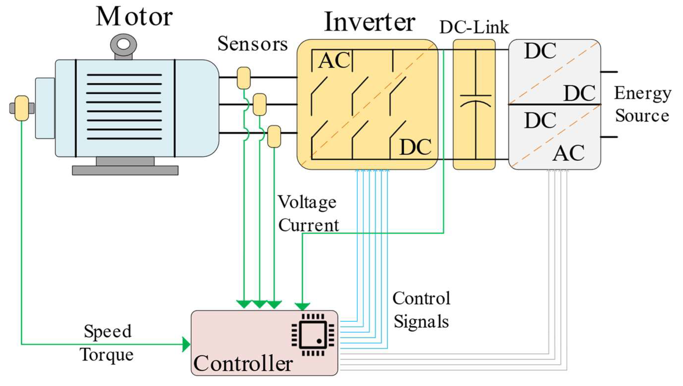
2.1. Drive Topology
2.2. Machine Faults
2.2.1. Bearing Faults
2.2.2. Stator- and Rotor-Related Faults
2.3. Power Electronics Faults
2.4. Sensor Faults
2.5. DC Link Capacitor Fault
3. Fault Detection and Diagnosis in Electric Machines
- Statistical Methods;
- Machine-Learning (ML)-Based Methods;
- Deep-Learning (DL)-Based Methods.
3.1. Statistical Approaches
3.1.1. Bearing Faults
3.1.2. Stator and Rotor Faults
3.2. ML-Based Methods
3.2.1. Bearing Faults

| Method | Analysis Type | MT 1 | Fault Type | Used Signals | Fault Indicator | Svrty? 7 | Ref. |
|---|---|---|---|---|---|---|---|
| Improved Dynamic System Model with Particle Filtering | St 2 | - | Bearing | Vibration | Deviation from healthy operation based on healthy model | No | [35] |
| Complementary Ensemble Empirical Mode Decomposition, Weighted Multiscale Entropy | St 2 | IM | Bearing | Vibration | Refined Composite Multiscale RMS (RCRMS), Kurtosis | Yes | [36] |
| Sparse Code Shrinkage Denoising, Fast Spectral Correlation | Frq 3 | - | Bearing | Vibration | Ball pass frequency | No | [38] |
| Angle Domain Conversion, Variational Mode Decomposition | Frq 3 | - | Bearing | Vibration, Speed | Recurring frequency components in angle domain | No | [40] |
| Basic Statistics | St 2 | IM | Bearing | Stray Flux | Mean value difference in stary flux measurements | Yes | [43] |
| Fourier Analysis | Frq 3 | BLDC | Stator IT 4 | Current | The third harmonic in negative frequency | Yes | [47] |
| Current Harmonic Analysis | Frq 3 | PMSM | DeMgt 5 | Current | Amplitude of certain harmonic orders | No | [48] |
| Motor Current Signature Analysis | Frq 3 | BLDC | Stator IT 4 | Vibration, Current | The third harmonic in current spectrum | Yes | [49] |
| MUSIC | Frq 3 | IM | BRB | Current | Double multiples of slip frequency in Fourier analysis | Yes | [54] |
| Multiple Reference Frames, MCSA | Frq 3 | IM | Stator IT 4 | Current | The third harmonic in current spectrum | Yes | [56] |
| Fourier Analysis | Frq 3 | IM | BRB | Stray Flux | Increased amplitude on flux spectrum at | Yes | [57] |
| Sensor Measurement Difference | Time | IM | BRB, Ecc 6 | Internal Flux | Difference in airgap flux densities in similar poles | Yes | [58] |
| Sensor Measurement Difference | Time | PMSM | Ecc 6, DeMgt 5 | Flux | Normalized changes in flux measurements | Yes | [59] |
| Flux Vector Analysis | Frq 3 | IM | Stator IT 4 | Flux | Amplitude increments of frequency in Flux Vector FFT | Yes | [60] |
| Stray Flux Analysis | Frq 3 | PMSM | Stator IT 4 | Flux | 3rd harmonic of stray flux | Yes | [61] |
| Flux Spectrum Analysis | Frq 3 | PMSM | DeMgt 5 | Leakage Flux | Amplitude of certain harmonic orders | Yes | [62] |
3.2.2. Stator and Rotor Faults
| Method | MT 1 | FT 2 | Used Signals | FE 3 | FS 4 | Classifier | Acc 5 | Svrty? 6 | Ref. |
|---|---|---|---|---|---|---|---|---|---|
| H-MLP 14 | IM | Bearing | Vibration | STD 7, CCA 8 | Discriminant Analysis | H-MLP | 95% | Yes | [18] |
| NN filter MLP | IM | Bearing | Vibration | TD 9 | Removing Nonbearing Fault Component (RNFC) filter | MLP | 96–100% | Yes | [33] |
| RF | IM | Bearing | Vibration | St 10 | Recursive Feature Elimination (RFE) | RF 15 | 96.7–100% | Yes | [34] |
| SVM | IM | Bearing | Thermography | DWT 11, St | PCA, Mahalanobis distance (MD) | SVM 16 | 100% | Yes | [42] |
| SVM | IM | SIT 18 | Stator Current | DWT, St | - | SVM | 99.74% | Yes | [50] |
| kNN | PMSM | SIT | Stator Current | FFT | - | kNN | 99.10% | Yes | [51] |
| RF | PMSM | BRB | Stator Current | STD | Feature Importance Based | RF | 98.40% | No | [52] |
| MLP | IM | SIT | Stator Current | Sampled Measurement | - | MLP | 100% | Yes | [53] |
| NN | IM | SIT | Torque | St, FD 12 | - | NN | 88–100% | Yes | [63] |
| XGBoost | PMSM | Bearing | Stator Current | DWT, TFD 13 | - | XGBoost 17 | 99.30% | Yes | [66] |
| SVM | PMSM | Ecc 19, Broken Magnet | Stator Current | FD | LDA 20 | SVM | 96%+ | Yes | [67] |
3.3. DL-Based Methods
3.3.1. Bearing Faults
3.3.2. Stator and Rotor Faults
| Architecture | Data Source | Fault Type | Used Signals | Classifier | Accuracy | Severity? | Ref. |
|---|---|---|---|---|---|---|---|
| CNN, Physics Informed | CWRU | Bearing | Vibration | Softmax | 91.82–99.97% | Yes | [37] |
| Autoencoder with Memory | XJTU-SY, NASA-IMS | Bearing | Vibration | Residual Autoregression Estimator | 97.97% | No | [39] |
| CNN | IM Experiment | Stator Inter-turn | Stator Current | Softmax | 99.30% | Yes | [46] |
| CNN | CWRU, Experiments | Bearing | Vibration | - | 99.48–100% | Multiple Types | [68] |
| GAN, Auto Encoder | CWRU | Bearing | Vibration | Auto Encoder | 99.20% | Multiple Types | [69] |
| Sparse Auto Encoder | IM Experiment | BRB, Bearing, Stator Winding, | Vibration | DNN | 93.5–100% | Multiple Faults | [71] |
| Deep-SincNet | IM Experiment | Bearing, BRB | Stator Current | Softmax | 99.93% | Multiple Severities/Faults | [72] |
3.4. Machine Faults Data Repositories
| Dataset Source | Acronym | Ref. |
|---|---|---|
| Case Western Reserve University | CWRU | [73] |
| Xi’an Jiaotong University and Changxing Sumyoung Technology Co., Ltd., Changxing, China | XJTU-SY | [74] |
| NSF I/UCR Center for Intelligent Maintenance Systems | NASA-IMS | [75] |
| NASA–FEMTO | PRONOSTIA | [76] |
4. Fault Detection and Diagnosis in Power Electronics
- Logic-based methods;
- Residual-based methods;
- Controller-aided methods.
4.1. Logic-Based Methods
4.2. Residual-Based Methods
4.3. Controller-Aided Methods
5. Fault Detection and Diagnosis in Sensors
| Method | Topology | Modulation | Fault Type | Switch Type | Used Signals | Scalable | Ref. |
|---|---|---|---|---|---|---|---|
| Logic Based | Independent | Independent | OC, SC | IGBT | Gate voltage | Yes | [77] |
| Logic Based | Independent | Independent | OC, SC | SiC | Gate voltage | Yes | [78] |
| Logic Based | Independent | Independent | SC | GaN HEMT | Phase voltage | Yes | [79] |
| Logic Based | H-Bridge Inverter | LS-SPWM | OC | Any | Output Voltage, load current | Yes | [80] |
| Logic Based | 3-phase Inverter | SVM PWM | OC, Current Sensor | Any | 3-phase currents | No | [81] |
| Logic Based * | 3-phase Inverter | SPWM–Expandable | OC | Any | 3-phase currents | No | [82] |
| Logic Based | CHB MLI | SPWM | OC | Any | Current and Voltage Per Leg | Yes | [83] |
| Logic Based | 3-phase Inverter | SPWM | OC | Any | 2 phase currents | No | [84] |
| Logic Based | Modified 3-phase Inverter | SVM PWM | OC SC | Any | Input current, gate signals, gate voltage | No | [85] |
| Logic Based * | 3-phase Inverter | SVM PWM | OC, Speed, and Current Sensor | Any | 3-phase current, speed | No | [86] |
| Residual Based | 3-phase Inverter | SPWM | OC | Any | 3-phase currents, Gate signals | No | [87] |
| Residual Based | 3-phase Inverter | SVM PWM | OC | Any | 3-phase currents | No | [88] |
| Residual Based | MLI | NA | OC | Any | Module voltage, load current, circulating current | Yes | [89] |
| Residual Based | 3-phase Inverter | NA | OC | Any | 3-phase currents | No | [90] |
| Residual Based | 3-phase Inverter | Async.-Sync Hybrid Modulation | OC, Current Sensor | Any | 3-phase currents | No | [91] |
| Residual Based | 3-phase Inverter | NA | OC, Current Sensor | Any | 3-line voltage, 3-phase voltage | No | [92] |
| Residual Based | Independent | Independent | OC, SC | Si, SiC MOSFET | Device voltage, device current, case temperature | Yes | [93] |
| Controller Aided | 3-phase Inverter | SVM PWM | OC, Current Sensor | Any | 3-phase currents | No | [94] |
| Controller Aided | 3-phase Inverter | SPWM | OC | Any | 3-phase voltage, 3-phase current | No | [95] |
| Controller Aided | MLI | MPC Based | OC | Any | Module voltage | Yes | [96] |
| Controller Aided | MLI | NA | OC | Any | Module input voltage, module current | Yes | [97] |
6. DC Link Capacitor Fault Detection
7. Conclusions, Challenges, and Future Work
Author Contributions
Funding
Conflicts of Interest
References
- Alshorman, O.; Alshorman, A. A review of intelligent methods for condition monitoring and fault diagnosis of stator and rotor faults of induction machines. Int. J. Electr. Comput. Eng. 2021, 11, 2820–2829. [Google Scholar] [CrossRef]
- Khan, M.A.; Asad, B.; Kudelina, K.; Vaimann, T.; Kallaste, A. The Bearing Faults Detection Methods for Electrical Machines—The State of the Art. Energies 2023, 16, 296. [Google Scholar] [CrossRef]
- Li, D.; Wang, Y.; Wang, J.; Wang, C.; Duan, Y. Recent advances in sensor fault diagnosis: A review. Sens. Actuators A Phys. 2020, 309, 111990. [Google Scholar] [CrossRef]
- Kumar, P.; Hati, A.S. Review on Machine Learning Algorithm Based Fault Detection in Induction Motors. Arch. Comput. Methods Eng. 2021, 28, 1929–1940. [Google Scholar] [CrossRef]
- Gonzalez-Jimenez, D.; Del-Olmo, J.; Poza, J.; Garramiola, F.; Sarasola, I. Machine learning-based fault detection and diagnosis of faulty power connections of induction machines. Energies 2021, 14, 4886. [Google Scholar] [CrossRef]
- Zhang, S.; Zhang, S.; Wang, B.; Habetler, T.G. Deep Learning Algorithms for Bearing Fault Diagnostics—A Comprehensive Review. IEEE Access 2020, 8, 29857–29881. [Google Scholar] [CrossRef]
- Liang, X.; Member, S.; Ali, M.Z.; Member, S. Induction Motors Fault Diagnosis Using Finite Element Method: A Review. IEEE Trans. Ind. Appl. 2020, 56, 1205–1217. [Google Scholar] [CrossRef]
- Liu, Y.; Bazzi, A.M. A review and comparison of fault detection and diagnosis methods for squirrel-cage induction motors: State of the art. ISA Trans. 2017, 70, 400–409. [Google Scholar] [CrossRef]
- Xu, X.; Qiao, X.; Zhang, N.; Feng, J.; Wang, X. Review of intelligent fault diagnosis for permanent magnet synchronous motors in electric vehicles. Adv. Mech. Eng. 2020, 12, 1–14. [Google Scholar] [CrossRef]
- He, J.; Yang, Q.; Wang, Z. On-line fault diagnosis and fault-tolerant operation of modular multilevel converters—A comprehensive review. CES Trans. Electr. Mach. Syst. 2021, 4, 360–372. [Google Scholar] [CrossRef]
- Hassan, O.E.; Amer, M.; Abdelsalam, A.K.; Williams, B.W. Induction motor broken rotor bar fault detection techniques based on fault signature analysis—A review. IET Electr. Power Appl. 2018, 12, 895–907. [Google Scholar] [CrossRef]
- Neupane, D.; Seok, J. Bearing fault detection and diagnosis using case western reserve university dataset with deep learning approaches: A review. IEEE Access 2020, 8, 93155–93178. [Google Scholar] [CrossRef]
- Riera-Guasp, M.; Antonino-Daviu, J.A.; Capolino, G.A. Advances in electrical machine, power electronic, and drive condition monitoring and fault detection: State of the art. IEEE Trans. Ind. Electron. 2015, 62, 1746–1759. [Google Scholar] [CrossRef]
- Tang, Q.; Shu, X.; Zhu, G.; Wang, J.; Yang, H. Reliability study of bev powertrain system and its components—A case study. Processes 2021, 9, 762. [Google Scholar] [CrossRef]
- Shu, X.; Guo, Y.; Yang, W.; Wei, K.; Zhu, Y.; Zou, H. A Detailed Reliability Study of the Motor System in Pure Electric Vans by the Approach of Fault Tree Analysis. IEEE Access 2020, 8, 5295–5307. [Google Scholar] [CrossRef]
- Singh, G.K.; Al Kazzaz SA, S. Induction machine drive condition monitoring and diagnostic research—A survey. Electr. Power Syst. Res. 2003, 64, 145–158. [Google Scholar] [CrossRef]
- Neupane, D.; Kim, Y.; Seok, J. Bearing Fault Detection Using Scalogram and Switchable Normalization-Based CNN (SN-CNN). IEEE Access 2021, 9, 88151–88166. [Google Scholar] [CrossRef]
- Prieto, M.D.; Cirrincione, G.; Espinosa, A.G.; Ortega, J.A.; Henao, H. Bearing fault detection by a novel condition-monitoring scheme based on statistical-time features and neural networks. IEEE Trans. Ind. Electron. 2013, 60, 3398–3407. [Google Scholar] [CrossRef]
- Immovilli, F.; Bellini, A.; Rubini, R.; Tassoni, C. Diagnosis of bearing faults in induction machines by vibration or current signals: A critical comparison. IEEE Trans. Ind. Appl. 2010, 46, 1350–1359. [Google Scholar] [CrossRef]
- Elbouchikhi, E.; Amirat, Y.; Feld, G.; Benbouzid, M. Generalized likelihood ratio test based approach for stator-fault detection in a PWM inverter-fed induction motor drive. IEEE Trans. Ind. Electron. 2019, 66, 6343–6353. [Google Scholar] [CrossRef]
- Siddique, A.; Yadava, G.S.; Singh, B. A review of stator fault monitoring techniques of induction motors. IEEE Trans. Energy Convers. 2005, 20, 106–114. [Google Scholar] [CrossRef]
- Jung, J.H.; Lee, J.J.; Kwon, B.H. Online diagnosis of induction motors using MCSA. IEEE Trans. Ind. Electron. 2006, 53, 1842–1852. [Google Scholar] [CrossRef]
- Milkovic, D. Brief review of motor current signature analysis. HDKBR INFO Mag. 2015, 5, 14–26. [Google Scholar]
- Toliyat, H.A.; Nandi, S.; Choi, S.; Meshgin-Kelk, H. Electric Machines: Modeling, Condition Monitoring, and Fault Diagnosis; CRC Press: Boca Raton, FL, USA, 2012. [Google Scholar]
- Chen, W.; Zhang, L.; Pattipati, K.; Bazzi, A.M.; Joshi, S.; Dede, E.M. Data-Driven Approach for Fault Prognosis of SiC MOSFETs. IEEE Trans. Power Electron. 2020, 35, 4048–4062. [Google Scholar] [CrossRef]
- Morozumi, A.; Yamada, K.; Miyasaka, T.; Sumi, S.; Seki, Y. Reliability of power cycling for IGBT power semiconductor modules. IEEE Trans. Ind. Appl. 2003, 39, 665–671. [Google Scholar] [CrossRef]
- Franke, J.; Zeng, G.; Winkler, T.; Lutz, J. Power cycling reliability results of GaN HEMT devices. In Proceedings of the International Symposium on Power Semiconductor Devices and ICs 2018, Chicago, IL, USA, 13–17 May 2018; pp. 467–470. [Google Scholar] [CrossRef]
- Meneghini, M.; Fabris, E.; Ruzzarin, M.; De Santi, C.; Nomoto, K.; Hu, Z.; Li, W.; Gao, X.; Jena, D.; Xing, H.G.; et al. Degradation Mechanisms of GaN-Based Vertical Devices: A Review. Phys. Status Solidi (A) Appl. Mater. Sci. 2020, 217, 1900750. [Google Scholar] [CrossRef]
- Xu, C.; Yang, F.; Ugur, E.; Pu, S.; Akin, B. Performance Degradation of GaN HEMTs Under Accelerated Power Cycling Tests. CPSS Trans. Power Electron. Appl. 2018, 3, 269–277. [Google Scholar] [CrossRef]
- Falck, J.; Felgemacher, C.; Rojko, A.; Liserre, M.; Zacharias, P. Reliability of Power Electronic Systems. IEEE Ind. Electron. Mag. 2018, 12, 24–35. [Google Scholar] [CrossRef]
- Zhao, Z.; Davari, P.; Lu, W.; Wang, H.; Blaabjerg, F. An Overview of Condition Monitoring Techniques for Capacitors in DC-Link Applications. IEEE Trans. Power Electron. 2021, 36, 3692–3716. [Google Scholar] [CrossRef]
- Wang, T.; Liu, Z.; Lu, G.; Liu, J. Temporal-Spatio Graph Based Spectrum Analysis for Bearing Fault Detection and Diagnosis. IEEE Trans. Ind. Electron. 2021, 68, 2598–2607. [Google Scholar] [CrossRef]
- Huang, X.; Wen, G.; Dong, S.; Zhou, H.; Lei, Z.; Zhang, Z.; Chen, X. Memory Residual Regression Autoencoder for Bearing Fault Detection. IEEE Trans. Instrum. Meas. 2021, 70, 3515512. [Google Scholar] [CrossRef]
- Zarei, J.; Tajeddini, M.A.; Karimi, H.R. Vibration analysis for bearing fault detection and classification using an intelligent filter. Mechatronics 2014, 24, 151–157. [Google Scholar] [CrossRef]
- Roy, S.S.; Dey, S.; Chatterjee, S. Autocorrelation Aided Random Forest Classifier-Based Bearing Fault Detection Framework. IEEE Sens. J. 2020, 20, 10792–10800. [Google Scholar] [CrossRef]
- Zhang, B.; Sconyers, C.; Byington, C.; Patrick, R.; Orchard, M.E.; Vachtsevanos, G. A probabilistic fault detection approach: Application to bearing fault detection. IEEE Trans. Ind. Electron. 2011, 58, 2011–2018. [Google Scholar] [CrossRef]
- Minhas, A.S.; Kankar, P.K.; Kumar, N.; Singh, S. Bearing fault detection and recognition methodology based on weighted multiscale entropy approach. Mech. Syst. Signal Process. 2021, 147, 107073. [Google Scholar] [CrossRef]
- Shen, S.; Lu, H.; Sadoughi, M.; Hu, C.; Nemani, V.; Thelen, A.; Webster, K.; Darr, M.; Sidon, J.; Kenny, S. A physics-informed deep learning approach for bearing fault detection. Eng. Appl. Artif. Intell. 2021, 103, 104295. [Google Scholar] [CrossRef]
- Li, J.; Yu, Q.; Wang, X.; Zhang, Y. An enhanced rolling bearing fault detection method combining sparse code shrinkage denoising with fast spectral correlation. ISA Trans. 2020, 102, 335–346. [Google Scholar] [CrossRef]
- Tang, G.; Wang, Y.; Huang, Y.; Liu, N.; He, J. Compound Bearing Fault Detection Under Varying Speed Conditions With Virtual Multichannel Signals in Angle Domain. IEEE Trans. Instrum. Meas. 2020, 69, 5535–5545. [Google Scholar] [CrossRef]
- Barcelos, A.S.; Marques Cardoso, A.J. Current-based bearing fault diagnosis using deep learning algorithms. Energies 2021, 14, 2509. [Google Scholar] [CrossRef]
- Choudhary, A.; Goyal, D.; Letha, S.S. Infrared Thermography-Based Fault Diagnosis of Induction Motor Bearings Using Machine Learning. IEEE Sens. J. 2021, 21, 1727–1734. [Google Scholar] [CrossRef]
- Frosini, L.; Harlisca, C.; Szabo, L. Induction machine bearing fault detection by means of statistical processing of the stray flux measurement. IEEE Trans. Ind. Electron. 2015, 62, 1846–1854. [Google Scholar] [CrossRef]
- Tang, J.; Chen, J.; Dong, K.; Yang, Y.; Lv, H.; Liu, Z. Modeling and evaluation of stator and rotor faults for induction motors. Energies 2019, 13, 133. [Google Scholar] [CrossRef]
- Tang, J.; Yang, Y.; Chen, J.; Qiu, R.; Liu, Z. Characteristics analysis and measurement of inverter-fed induction motors for stator and rotor fault detection. Energies 2019, 13, 101. [Google Scholar] [CrossRef]
- Skowron, M.; Orlowska-Kowalska, T.; Wolkiewicz, M.; Kowalski, C.T. Convolutional neural network-based stator current data-driven incipient stator fault diagnosis of inverter-fed induction motor. Energies 2020, 13, 1475. [Google Scholar] [CrossRef]
- Lee, S.T.; Hur, J. Detection technique for stator inter-turn faults in BLDC motors based on third-harmonic components of line currents. IEEE Trans. Ind. Appl. 2017, 53, 143–150. [Google Scholar] [CrossRef]
- Cruz SM, A.; Cardoso AJ, M. Diagnosis of stator inter-turn short circuits in DTC induction motor drives. IEEE Trans. Ind. Appl. 2004, 40, 1349–1360. [Google Scholar] [CrossRef]
- Wang, C.; Delgado Prieto, M.; Romeral, L.; Chen, Z.; Blaabjerg, F.; Liu, X. Detection of Partial Demagnetization Fault in PMSMs Operating under Nonstationary Conditions. IEEE Trans. Magn. 2016, 52, 3–6. [Google Scholar] [CrossRef]
- Shifat, T.A.; Hur, J.W. An Effective Stator Fault Diagnosis Framework of BLDC Motor Based on Vibration and Current Signals. IEEE Access 2020, 8, 106968–106981. [Google Scholar] [CrossRef]
- Akhil Vinayak, B.; Anjali Anand, K.; Jagadanand, G. Wavelet-based real-time stator fault detection of inverter-fed induction motor. IET Electr. Power Appl. 2020, 14, 82–90. [Google Scholar] [CrossRef]
- Pietrzak, P.; Wolkiewicz, M. On-line detection and classification of pmsm stator winding faults based on stator current symmetrical components analysis and the knn algorithm. Electronics 2021, 10, 1786. [Google Scholar] [CrossRef]
- Quiroz, J.C.; Mariun, N.; Mehrjou, M.R.; Izadi, M.; Misron, N.; Mohd Radzi, M.A. Fault detection of broken rotor bar in LS-PMSM using random forests. Meas. J. Int. Meas. Confed. 2018, 116, 273–280. [Google Scholar] [CrossRef]
- Palacios RH, C.; Da Silva, I.N.; Goedtel, A.; Godoy, W.F.; Lopes, T.D. Diagnosis of Stator Faults Severity in Induction Motors Using Two Intelligent Approaches. IEEE Trans. Ind. Inform. 2017, 13, 1681–1691. [Google Scholar] [CrossRef]
- Singh, G.; Naikan VN, A. Detection of half broken rotor bar fault in VFD driven induction motor drive using motor square current MUSIC analysis. Mech. Syst. Signal Process. 2018, 110, 333–348. [Google Scholar] [CrossRef]
- Ramu, S.K.; Raj Irudayaraj, G.C.; Subramani, S.; Subramaniam, U. Broken rotor bar fault detection using Hilbert transform and neural networks applied to direct torque control of induction motor drive. IET Power Electron. 2020, 13, 3328–3338. [Google Scholar] [CrossRef]
- Park, Y.; Yang, C.; Kim, J.; Kim, H.; Bin Lee, S.; Gyftakis, K.N.N.; Panagiotou, P.A.; Kia, S.H.; Capolino, G.-A. Stray flux monitoring for reliable detection of rotor faults under the influence of rotor axial air ducts. IEEE Trans. Ind. Electron. 2019, 66, 7561–7570. [Google Scholar] [CrossRef]
- Mirzaeva, G.; Saad, K.I. Advanced Diagnosis of Rotor Faults and Eccentricity in Induction Motors Based on Internal Flux Measurement. IEEE Trans. Ind. Appl. 2018, 54, 3961–3970. [Google Scholar] [CrossRef]
- Park, Y.; Yang, C.; Bin Lee, S.; Lee, D.-M.; Fernandez, D.; Reigosa, D.; Briz, F. Online detection and classification of rotor and load defects in PMSMs Based on Hall sensor measurements. IEEE Trans. Ind. Appl. 2019, 55, 3803–3812. [Google Scholar] [CrossRef]
- Gyftakis, K.N.; Cardoso AJ, M. Reliable Detection of Stator Interturn Faults of Very Low Severity Level in Induction Motors. IEEE Trans. Ind. Electron. 2021, 68, 3475–3484. [Google Scholar] [CrossRef]
- Gurusamy, V.; Bostanci, E.; Li, C.; Qi, Y.; Akin, B. A Stray Magnetic Flux-Based Robust Diagnosis Method for Detection and Location of Interturn Short Circuit Fault in PMSM. IEEE Trans. Instrum. Meas. 2021, 70, 3500811. [Google Scholar] [CrossRef]
- Goktas, T.; Zafarani, M.; Lee, K.W.; Akin, B.; Sculley, T. Comprehensive Analysis of Magnet Defect Fault Monitoring Through Leakage Flux. IEEE Trans. Magn. 2017, 53, 8201010. [Google Scholar] [CrossRef]
- Maraaba, L.; Al-Hamouz, Z.; Abido, M. An efficient stator inter-Turn fault diagnosis tool for induction motors. Energies 2018, 11, 653. [Google Scholar] [CrossRef]
- Glowacz, A.; Glowacz, W.; Glowacz, Z.; Kozik, J. Early fault diagnosis of bearing and stator faults of the single-phase induction motor using acoustic signals. Meas. J. Int. Meas. Confed. 2018, 113, 1–9. [Google Scholar] [CrossRef]
- Glowacz, A. Fault diagnosis of single-phase induction motor based on acoustic signals. Mech. Syst. Signal Process. 2019, 117, 65–80. [Google Scholar] [CrossRef]
- Toma, R.N.; Kim, J.M. Article bearing fault classification of induction motors using discrete wavelet transform and ensemble machine learning algorithms. Appl. Sci. 2020, 10, 5251. [Google Scholar] [CrossRef]
- Heydarzadeh, M.; Zafarani, M.; Nourani, M.; Akin, B. A Wavelet-Based Fault Diagnosis Approach for Permanent Magnet Synchronous Motors. IEEE Trans. Energy Convers. 2019, 34, 761–772. [Google Scholar] [CrossRef]
- Wen, L.; Li, X.; Gao, L.; Zhang, Y. A New Convolutional Neural Network-Based Data-Driven Fault Diagnosis Method. IEEE Trans. Ind. Electron. 2018, 65, 5990–5998. [Google Scholar] [CrossRef]
- Mao, W.; Liu, Y.; Ding, L.; Li, Y. Imbalanced fault diagnosis of rolling bearing based on generative adversarial network: A comparative study. IEEE Access 2019, 7, 9515–9530. [Google Scholar] [CrossRef]
- Zhuang, F.; Qi, Z.; Duan, K.; Xi, D.; Zhu, Y.; Zhu, H.; Xiong, H.; He, Q. A Comprehensive Survey on Transfer Learning. Proc. IEEE 2021, 109, 43–76. [Google Scholar] [CrossRef]
- Sun, W.; Shao, S.; Zhao, R.; Yan, R.; Zhang, X.; Chen, X. A sparse auto-encoder-based deep neural network approach for induction motor faults classification. Meas. J. Int. Meas. Confed. 2016, 89, 171–178. [Google Scholar] [CrossRef]
- Abid, F.; Sallem, M.B.; Braham, A. Robust Interpretable Deep Learning for Intelligent Fault Diagnosis of Induction Motors. IEEE Trans. Instrum. Meas. 2020, 69, 3506–3515. [Google Scholar] [CrossRef]
- Case Western Reserve University Bearing Data Center Seeded Fault Test Data. (n.d.). Available online: https://engineering.case.edu/bearingdatacenter (accessed on 24 July 2023).
- Xi’an Jiaotong University—Sumyoung Technology (XJTU-SY) Bearing Datasets. (n.d.). Available online: https://biaowang.tech/xjtu-sy-bearing-datasets/ (accessed on 24 July 2023).
- Lee, J.; Qiu, H.; Yu, G.; Lin, J.; Services, R.T.; Lee, H.; Qiu, G.; Yu, J.L. Bearing Data Set. IMS, University of Cincinnati. 2007. Available online: https://www.nasa.gov/content/prognostics-center-of-excellence-data-set-repository (accessed on 24 July 2023).
- Repository, N.P.D. (n.d.). FEMTO Bearing Data Set. Available online: https://www.nasa.gov/content/prognostics-center-of-excellence-data-set-repository (accessed on 24 July 2023).
- Rodríguez-Blanco, M.A.; Claudio-Sánchez, A.; Theilliol, D.; Vela-Valdés, L.G.; Sibaja-Terán, P.; Hernández-González, L.; Aguayo-Alquicira, J. A failure-detection strategy for IGBT based on gate-voltage behavior applied to a motor drive system. IEEE Trans. Ind. Electron. 2011, 58, 1625–1633. [Google Scholar] [CrossRef]
- Climaco-Arvizu, O.; Hernández-González, L.; Rodríguez-Blanco, M.A. Fault detection for SiC-Mosfet based on the behavior of gate signal. In Proceedings of the SDEMPED 2015: IEEE 10th International Symposium on Diagnostics for Electrical Machines, Power Electronics and Drives, Guarda, Portugal, 1–4 September 2015; pp. 71–76. [Google Scholar] [CrossRef]
- Lyu, X.; Li, H.; Abdullah, Y.; Wang, K.; Hu, B.; Yang, Z.; Liu, J.; Wang, J.; Liu, L.; Bala, S. A Reliable Ultrafast Short-Circuit Protection Method for E-Mode GaN HEMT. IEEE Trans. Power Electron. 2020, 35, 8926–8933. [Google Scholar] [CrossRef]
- Kumar, M. Open Circuit Fault Detection and Switch Identification for LS-PWM H-Bridge Inverter. IEEE Trans. Circuits Syst. II Express Briefs 2021, 68, 1363–1367. [Google Scholar] [CrossRef]
- El Khil, S.K.; Jlassi, I.; Marques Cardoso, A.J.; Estima, J.O.; Mrabet-Bellaaj, N. Diagnosis of Open-Switch and Current Sensor Faults in PMSM Drives through Stator Current Analysis. IEEE Trans. Ind. Appl. 2019, 55, 5925–5937. [Google Scholar] [CrossRef]
- Li, K.; Cheng, S.; Yu, T.; Wu, X.; Xiang, C.; Bilal, A. An On-Line Multiple Open-Circuit Fault Diagnostic Technique for Railway Vehicle Air-Conditioning Inverters. IEEE Trans. Veh. Technol. 2020, 69, 7026–7039. [Google Scholar] [CrossRef]
- Lamb, J.; Mirafzal, B. Open-Circuit IGBT Fault Detection and Location Isolation for Cascaded Multilevel Converters. IEEE Trans. Ind. Electron. 2017, 64, 4846–4856. [Google Scholar] [CrossRef]
- Trabelsi, M.; Boussak, M.; Benbouzid, M. Multiple criteria for high performance real-time diagnostic of single and multiple open-switch faults in ac-motor drives: Application to IGBT-based voltage source inverter. Electr. Power Syst. Res. 2017, 144, 136–149. [Google Scholar] [CrossRef]
- Farhadi, M.; Fard, M.T.; Abapour, M.; Hagh, M.T. DC-AC Converter-Fed Induction Motor Drive with Fault-Tolerant Capability under Open- and Short-Circuit Switch Failures. IEEE Trans. Power Electron. 2018, 33, 1609–1621. [Google Scholar] [CrossRef]
- Jlassi, I.; Cardoso AJ, M. A Single Method for Multiple IGBT, Current, and Speed Sensor Faults Diagnosis in Regenerative PMSM Drives. IEEE J. Emerg. Sel. Top. Power Electron. 2020, 8, 2583–2599. [Google Scholar] [CrossRef]
- Cai, B.; Zhao, Y.; Liu, H.; Xie, M. A Data-Driven Fault Diagnosis Methodology in Three-Phase Inverters for PMSM Drive Systems. IEEE Trans. Power Electron. 2017, 32, 5590–5600. [Google Scholar] [CrossRef]
- Yan, H.; Xu, Y.; Cai, F.; Zhang, H.; Zhao, W.; Gerada, C. PWM-VSI Fault Diagnosis for a PMSM Drive Based on the Fuzzy Logic Approach. IEEE Trans. Power Electron. 2018, 34, 759–768. [Google Scholar] [CrossRef]
- Kiranyaz, S.; Gastli, A.; Ben-Brahim, L.; Al-Emadi, N.; Gabbouj, M. Real-Time Fault Detection and Identification for MMC Using 1-D Convolutional Neural Networks. IEEE Trans. Ind. Electron. 2019, 66, 8760–8771. [Google Scholar] [CrossRef]
- Moosavi, S.S.; Kazemi, A.; Akbari, H. A comparison of various open-circuit fault detection methods in the IGBT-based DC/AC inverter used in electric vehicle. Eng. Fail. Anal. 2019, 96, 223–235. [Google Scholar] [CrossRef]
- Gou, B.; Xu, Y.; Xia, Y.; Deng, Q.; Ge, X. An Online Data-Driven Method for Simultaneous Diagnosis of IGBT and Current Sensor Fault of Three-Phase PWM Inverter in Induction Motor Drives. IEEE Trans. Power Electron. 2020, 35, 13281–13294. [Google Scholar] [CrossRef]
- Li, Z.; Wheeler, P.; Watson, A.; Costabeber, A.; Wang, B.; Ren, Y.; Bai, Z.; Ma, H. A Fast Diagnosis Method for Both IGBT Faults and Current Sensor Faults in Grid-Tied Three-Phase Inverters with Two Current Sensors. IEEE Trans. Power Electron. 2020, 35, 5267–5278. [Google Scholar] [CrossRef]
- Yang, Q.; Gultekin, M.A.; Seferian, V.; Pattipati, K.; Bazzi, A.M.; Palmieri, F.A.N.; Rajamani, R.; Joshi, S.; Farooq, M.; Ukegawa, H. Incipient Residual-Based Anomaly Detection in Power Electronic Devices. IEEE Trans. Power Electron. 2022, 37, 7315–7332. [Google Scholar] [CrossRef]
- Jlassi, I.; Estima, J.O.; El Khil, S.K.; Bellaaj, N.M.; Cardoso AJ, M. A Robust Observer-Based Method for IGBTs and Current Sensors Fault Diagnosis in Voltage-Source Inverters of PMSM Drives. IEEE Trans. Ind. Appl. 2017, 53, 2894–2905. [Google Scholar] [CrossRef]
- Maamouri, R.; Trabelsi, M.; Boussak, M.; M’Sahli, F. Fault Diagnosis and Fault Tolerant Control of a Three-Phase VSI Supplying Sensorless Speed Controlled Induction Motor Drive. Electr. Power Compon. Syst. 2018, 46, 2159–2173. [Google Scholar] [CrossRef]
- Zhou, D.; Yang, S.; Tang, Y. A Voltage-Based Open-Circuit Fault Detection and Isolation Approach for Modular Multilevel Converters with Model-Predictive Control. IEEE Trans. Power Electron. 2018, 33, 9866–9874. [Google Scholar] [CrossRef]
- Chai, M.; Gorla NB, Y.; Panda, S.K. Fault Detection and Localization for Cascaded H-Bridge Multilevel Converter with Model Predictive Control. IEEE Trans. Power Electron. 2020, 35, 10109–10120. [Google Scholar] [CrossRef]
- Salmasi, F.R. A Self-Healing Induction Motor Drive With Model Free Sensor Tampering and Sensor Fault Detection, Isolation, and Compensation. IEEE Trans. Ind. Electron. 2017, 64, 6105–6115. [Google Scholar] [CrossRef]
- Chakraborty, C.; Verma, V. Speed and current sensor fault detection and isolation technique for induction motor drive using axes transformation. IEEE Trans. Ind. Electron. 2015, 62, 1943–1954. [Google Scholar] [CrossRef]
- Skowron, M.; Teler, K.; Adamczyk, M.; Orlowska-Kowalska, T. Classification of Single Current Sensor Failures in Fault-Tolerant Induction Motor Drive Using Neural Network Approach. Energies 2022, 15, 6646. [Google Scholar] [CrossRef]
- Tran, C.D.; Palacky, P.; Kuchar, M.; Brandstetter, P.; Dinh, B.H. Current and Speed Sensor Fault Diagnosis Method Applied to Induction Motor Drive. IEEE Access 2021, 9, 38660–38672. [Google Scholar] [CrossRef]
- Gou, B.; Xu, Y.; Xia, Y.; Wilson, G.; Liu, S. An Intelligent Time-Adaptive Data-Driven Method for Sensor Fault Diagnosis in Induction Motor Drive System. IEEE Trans. Ind. Electron. 2019, 66, 9817–9827. [Google Scholar] [CrossRef]
- Dybkowski, M.; Klimkowski, K. Artificial neural network application for current sensors fault detection in the vector controlled induction motor drive. Sensors 2019, 19, 571. [Google Scholar] [CrossRef]
- Sun, P.; Gong, C.; Du, X.; Luo, Q.; Wang, H.; Zhou, L. Online Condition Monitoring for Both IGBT Module and DC-Link Capacitor of Power Converter Based on Short-Circuit Current Simultaneously. IEEE Trans. Ind. Electron. 2017, 64, 3662–3671. [Google Scholar] [CrossRef]
- Li, T.; Chen, J.; Cong, P.; Dai, X.; Qiu, R.; Liu, Z. Online Condition Monitoring of DC-Link Capacitor for AC/DC/AC PWM Converter. IEEE Trans. Power Electron. 2022, 37, 865–878. [Google Scholar] [CrossRef]
- Abo-Khalil, A.G.; Al-Qawasmi, A.R.; Eltamaly, A.M.; Yu, B.G. Condition monitoring of dc-link electrolytic capacitors in PWM power converters using OBL method. Sustainability 2020, 12, 3719. [Google Scholar] [CrossRef]
- Wechsler, A.; Mecrow, B.C.; Atkinson, D.J.; Bennett, J.W.; Benarous, M. Condition monitoring of DC-link capacitors in aerospace drives. IEEE Trans. Ind. Appl. 2012, 48, 1866–1874. [Google Scholar] [CrossRef]
- Seferian, V.; Bazzi, A.; Hajj, H. Condition Monitoring of DC-link Capacitors in Grid-tied Solar Inverters Using Data-Driven Techniques. In Proceedings of the 2020 IEEE Energy Conversion Congress and Exposition (ECCE), Detroit, MI, USA, 11–15 October 2020; pp. 5318–5323. [Google Scholar] [CrossRef]
- Sundararajan, P.; Sathik MH, M.; Sasongko, F.; Tan, C.S.; Tariq, M.; Simanjorang, R. Online Condition Monitoring System for DC-Link Capacitor in Industrial Power Converters. IEEE Trans. Ind. Appl. 2018, 54, 4775–4785. [Google Scholar] [CrossRef]
- Laadjal, K.; Sahraoui, M.; Cardoso AJ, M. On-Line Fault Diagnosis of DC-Link Electrolytic Capacitors in Boost Converters Using the STFT Technique. IEEE Trans. Power Electron. 2021, 36, 6303–6312. [Google Scholar] [CrossRef]


Disclaimer/Publisher’s Note: The statements, opinions and data contained in all publications are solely those of the individual author(s) and contributor(s) and not of MDPI and/or the editor(s). MDPI and/or the editor(s) disclaim responsibility for any injury to people or property resulting from any ideas, methods, instructions or products referred to in the content. |
© 2023 by the authors. Licensee MDPI, Basel, Switzerland. This article is an open access article distributed under the terms and conditions of the Creative Commons Attribution (CC BY) license (https://creativecommons.org/licenses/by/4.0/).
Share and Cite
Gultekin, M.A.; Bazzi, A. Review of Fault Detection and Diagnosis Techniques for AC Motor Drives. Energies 2023, 16, 5602. https://doi.org/10.3390/en16155602
Gultekin MA, Bazzi A. Review of Fault Detection and Diagnosis Techniques for AC Motor Drives. Energies. 2023; 16(15):5602. https://doi.org/10.3390/en16155602
Chicago/Turabian StyleGultekin, Muhammed Ali, and Ali Bazzi. 2023. "Review of Fault Detection and Diagnosis Techniques for AC Motor Drives" Energies 16, no. 15: 5602. https://doi.org/10.3390/en16155602
APA StyleGultekin, M. A., & Bazzi, A. (2023). Review of Fault Detection and Diagnosis Techniques for AC Motor Drives. Energies, 16(15), 5602. https://doi.org/10.3390/en16155602