1. Introduction
Limiting greenhouse gas emissions while supplying the rising demand for energy is a significant challenge for today’s society in light of climate change and global warming. As a major consumer of fossil energy, the transportation sector is a significant contributor to greenhouse gas emissions, accounting for 27% of total emissions in 2020 for the US [
1] and almost one-quarter of Europe’s emissions in 2019 [
2]. Despite the significant interest in electric vehicles and biofuels in relation to achieving zero and neutral carbon emissions, it is unlikely that complete abandonment of conventional internal combustion engines will occur in the near future. 40% of all new cars registered in the European Union in 2021 still run on gasoline. As hybrid cars continue to gain popularity, there is a growing focus on specialized gasoline engines for hybrid vehicles. These engines operate within a narrow range on the engine map, making extreme thermal efficiency improvements more significant compared to traditional engines. Combined with the increasingly stringent regulations, the SI engine therefore has to be improved with great effort in order to achieve lower pollution levels without sacrificing engine performance or market appeal [
3].
Direct injection spark ignition (DISI) engines are widely used in passenger cars. Among the various advanced technologies, lean combustion is becoming the most promising method to increase the thermal efficiency of DISI engines. Compared to the stoichiometric combustion, appropriately lean cylinder charge can significantly reduce the in-cylinder combustion temperature and heat transfer losses, as well as suppress knocking combustion, which also allows for the high compression ratio (CR). At the same time, diluted charge can improve the heat capacity ratio of mixture, which can significantly improve thermal efficiency. Lean combustion can also significantly reduce pumping losses of DISI working under medium and small loads by opening the throttle valve to achieve a better intake air flow, which also reduces fuel consumption [
4,
5]. Although lean combustion has lots of advantages, diluted charge creates huge challenges in terms of the ignition and combustion stability, which may result in misfire or combustion fluctuation due to weaker flame propagation under the lean condition [
6,
7]. Thus, a lot of research which aims at extending the lean-burn limit and enhancing combustion stability under ultra-lean conditions is being demonstrated, including a pre-chamber ignition system, HPIS (high-power ignition system) and stratified combustion scheme.
Pre-chamber is a two stage combustion concept of SI (spark ignition) engines. Adams [
8] investigated the effects of high-energy flame jets and combustion turbulence through the pre-chamber, and their results show an obvious reduction in combustion duration under lean mixture conditions. Ndsas et al. [
9] utilized a pre-chamber and extended the lean limit of the SI engine with port injection and in-cylinder direct injection. The extended lean-burn limit from 1.35 to 1.6 significantly improved thermal efficiency and reduced emissions of nitrogen oxides (
). Stadler et al. [
10] optimized the structure of a pre-chamber through three-dimensional numerical calculations. At the bench test, their results show that the lean limit could be extended to lambda = 1.8, and the peak thermal efficiency could be increased to 40%. According to the research of Jamrozik [
11], their engine was operated under an ultra-lean condition with
above 2.0, utilizing pre-chamber ignition; compared to the conventional SI engines, their results also demonstrated that a two-stage combustion process could contribute to a significant reduction in emissions.
A high-power ignition system is also an effective technology to achieve ultra-lean combustion. Jung et al. [
12] investigated the effects of increased spark discharge energy and higher in-cylinder turbulence level on lean combustion stability with a combination of ten spark coils (spark energy 250 mJ) and an intake port adapter. Their results show that the leanest stable operation at
= 1.9 and a 16.5% improvement in the indicated thermal efficiency was achieved. In his research, the author also shows the 0.2 ms interval is the best; unstable lean operation can result from either excessively short or overly long time intervals between spark discharges. Yu et al. [
13] applied a three-pole ignition spark plug for lean-burn research and observed that the stable operable lean combustion limit was extended from 1.61 for a stock spark plug to 1.84 for a three-pole ignition spark plug within a relatively low ignition energy range. Their study demonstrated that a multi-pole spark ignition strategy is helpful for flame kernels propagation. Joonsik Hwang [
14] utilized a plasma-assisted ignition system on a gasoline engine under lean conditions. In their engine test, combustion stability was obviously improved with smaller cycle-to-cycle fluctuations of in-cylinder pressure at
= 1.3 as well as an improvement in fuel efficiency up to 6%. Shen et al. [
15] observed that intake tumble flow and the increase in ignition energy achieved rapid propagation of the flame kernels on an optical engine, which accelerated the initial flame propagation speed and extended the lean combustion limit.
A stratified combustion scheme is helpful for improving distributions of in-cylinder mixture with the required concentration gradient in the combustion chamber. A rich mixture near the spark can enhance flame kernels generation and propagation in the initial combustion stage. Meanwhile, lean atmosphere is able to inhibit spontaneous combustion of the mixture and reduce knocking combustion. Duan et al. [
16] investigated a two-stage injection strategy in a stoichiometric DISI engine. Their study demonstrates that a suitable second injection timing (SIT) and second injection proportion (SIP) can literally mitigate in-cylinder pressure fluctuation and concentrate integral heat release. In another research study by Duan et al. [
17], a quantitative investigation of a fuel stratification strategy was launched in a DISI engine. The study demonstrates that with the retarding of SIT, CA50 of the combustion stage is advanced, and the peak heat release rate (HRR) increases. This suggests that increased combustion flame velocity is presented. Park’s research [
18,
19] which employed a spray-guided direct-injection system, showed that the lean combustion limit was extended to
= 2.0 in a DISI engine with a split-injection strategy. Their results demonstrate that the spray-guided direct-injection system is regarded as a promising technology to realize stratified lean combustion, and the necessary stratified mixture is important to guarantee stable combustion. Park et al. [
20] also observed an ultra-lean stratified combustion process on an optical single-cylinder engine with a quantities ratio of two injections of 1:1. In their research, compared to homogeneous lean combustion, IGN-Delay (Ignition timing to CA05) was much shorter under stratified lean combustion conditions, and the flame propagated faster. However, due to the retarding of SIT, the problem of fuel hitting the cylinder was very serious. This resulted in an increase in soot and unburned hydrocarbon (HC) emissions. Feng et al. [
21] studied the influences of a dual injection strategy on combustion and emission on an EGR-diluted GDI engine, and their results showed that the engine combustion and performance can be improved using a stratified mixture with EGR dilution. Compared to the homogeneous combustion, the particulate number and CO emissions deteriorated. Moriyoshi et al. [
22] proposed a new stratified combustion concept with stratified combustion layers parallel to the cylinder axis. The stratification was achieved by combining the special tumble port and a fuel injector. The test results show that parallel stratified combustion can accelerate flame propagation velocity under a lean-burn condition, then improves the lean combustion limit and combustion stability.
In the above studies, lean combustion could be realized by adopting pre-charmer ignition or a high-power ignition system, as well as utilizing a stratified fuel mixture with various injection strategies. However, the combustion instability and the control sensitivity under lean condition remain serious problems, and there is little research focused on the combustion control robustness. It is necessary to launch detailed investigations into the combustion process control under lean condition.
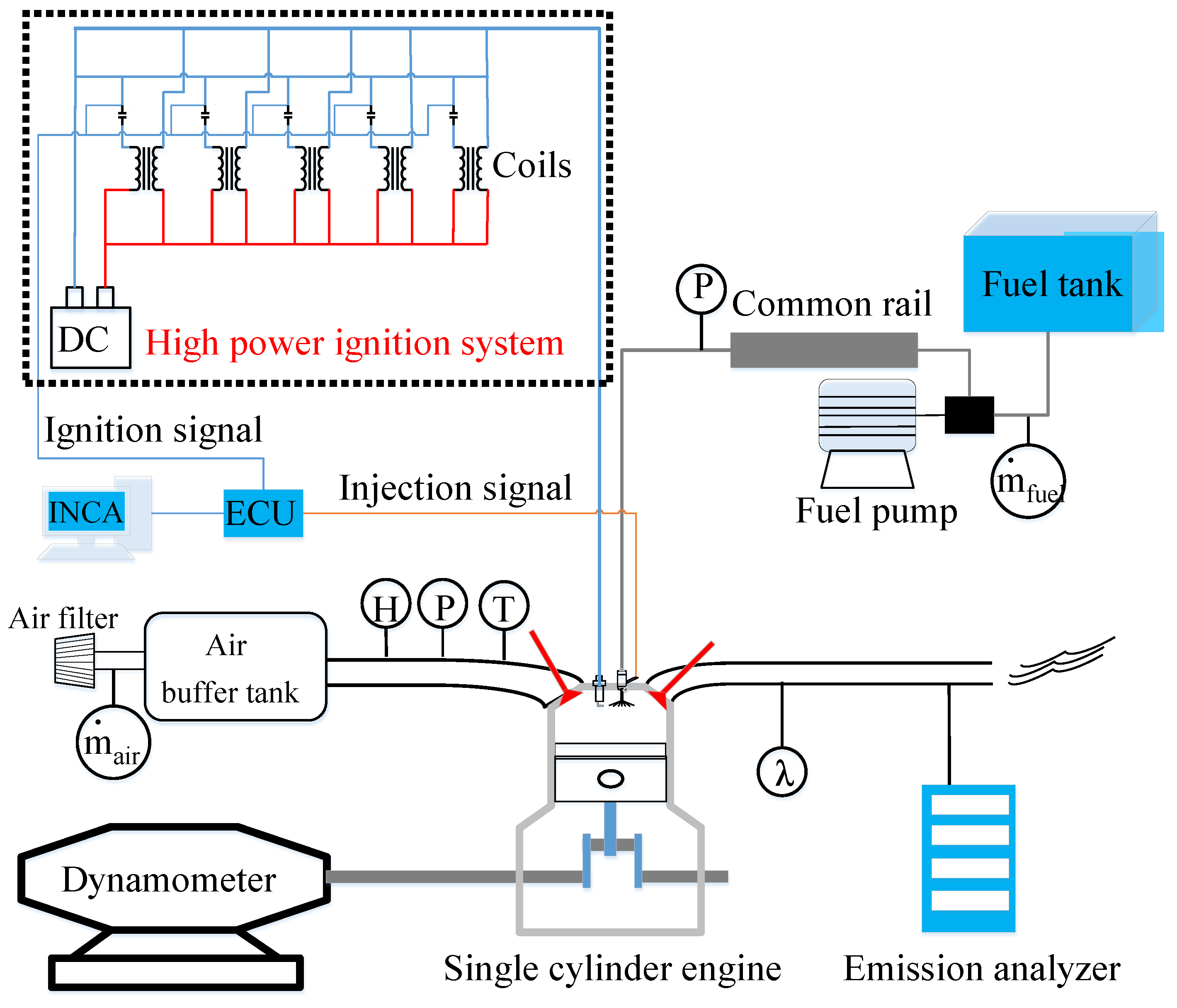
In the current research, a stratified ultra-lean combustion limit is realized by HPIS (424 mJ interval 0.2 ms) and dual-injection strategy on a single-cylinder DISI engine; because the knock tendency will lower at lean combustion, the CR geometry in this test is selected as 17:1. In order to extend the lean limit, thermal efficiency, combustion stability and control sensitivity, a detailed investigation of the stratified control strategies on combustion characteristic was conducted by altering the SIP, SIT and ignition timing. Based on the experimental results, the effects of the stratified strategy on lean mixture combustion ( = 1.6) and ultra-lean mixture combustion ( = 1.9) were examined and compared.
3. Results and Discussion
3.1. Effects of Single and Dual Injection on Extending Lean Combustion Limit
One of the objectives of the research is to investigate the effects of a stratified strategy involving dual injection on extending lean combustion limit. The experiment was first carried out under different lean conditions from
= 1.0 to
= 2.0. In this section, MIT was set at −300 °CA ATDC, and SIT was set at −180 °CA ATDC and SIP was set with 0 and 40%, respectively.
Figure 4 illustrates the variation in the indicated thermal efficiency
and
with the increasing of
. A persistent improvement of
is noticed with the increase in
, and as the mixture becomes leaner, stratified combustion with dual injection has a better thermal efficiency improvement than homogeneous combustion. The improvement should be resulted from the improvement of a specific heat ratio of mixture and reduction of combustion heat transfer losses. With all of the two injection strategies,
also shows a general increase with the increase in
, while homogeneous combustion cases exhibit a much higher trend at the deterioration of combustion stability under the leaner condition, resulting from the weaker robustness of flame kernel generation and propagation under lean and homogeneous conditions. The two cases reach the limit in
(5%) at
= 1.6 and
= 2.0, respectively. It can be expected that stratified combustion can effectively extend the lean combustion limit during ultra-lean operation of
= 2.0 with 5.6% improvement of
relative to that of the single fuel injection condition at
= 1.6.
Additionally, a short ING-Delay and short combustion duration are noticed in
Figure 5a, when the stratified combustion scheme is applied with dual injection. This showed that the flame kernel is robust and flame propagated faster during the combustion process, which resulted from an inadequate mixing process, and the relatively rich mixture clouds can be distributed near the spark plug.
Furthermore, the minimum advance spark timings for Maximum brake torque (MBT) and CA50 are shown in
Figure 5b. Compared to the case with homogeneous combustion, stratified combustion enhanced the initial flame kernel generation and propagation. More advanced spark timing can be set at stratified combustion. Combined with a shorter combustion duration, a more suitable CA50 position can be set. It is also worth noting that the NOx generation is also limited by the combustion temperature reduction due to the lean combustion, as shown in
Figure 6.
These results illustrate that stratified combustion via dual injection can actually extend the lean combustion limit to = 2.0 and accelerate the flame propagation velocity, which finally resulted in improving thermal efficiency and combustion robustness.
3.2. Effect of SIP on Lean Combustion and Ultra-Lean Combustion
In order to further understand the effects of stratified strategy on lean combustion, the influence of SIP needs to be discussed. This can influence the in-cylinder mixture concentration gradient. In this section, the test was carried out under the lean condition and the ultra-lean condition, respectively. The total fuel injection amount was fixed, and the engine speed was held at 2000 rpm and initial IMEP was 8.5 bar. Due to the limit of the minimum responding time of the injector, the minimum SIP under this working condition is 30%, and the maximum SIP is 45%, which is still less than the proportion of the main injection. The main and second fuel injection timings are −300 deg ATDC and −180 deg ATDC, respectively.
Table 3 shows a reverse trend at the change of peak in-cylinder pressure when SIP is increased under lean and ultra-lean conditions. For operation at lean condition
= 1.6, compared with Case (SIT = −180 °CA ATDC, SIP 45%), the case (SIT = −180 °CA ATDC, SIP 30%) exhibits a significant increase in the peak in-cylinder pressure value. By contrast, an obvious decrease in the peak in-cylinder value is noticed for the operation under the ultra-lean condition
= 1.9. A similarly reversed trend also can be observed in
Table 3, in which the
increased under the lean condition (
= 1.6) with the increase in SIP, while the reduction in
was significant under the ultra-lean condition (
= 1.9).
To find the reasons behind the observed reverse trends, data from the combustion phase are presented in
Figure 7a, in which ignition duration and combustion phases (CA50, CA90) of 100 continuous working cycles are shown. With the increase in SIP from 30% to 45%, trends of ignition delay, CA50 and CA90 all continue to decrease, while the different trends at CA50 and CA90 under different lean condition are noticed. Compared to (
= 1.6), there is a significant increase at the average value of CA50 and CA90 with the increase in SIP under the ultra-lean condition (
= 1.9). This suggests that increased SIP can literally increase the mixture concentration near the spark plug, and thus, enhanced flame kernel generation can be observed from the decreased IGN-Delay. However, as greater SIP is applied, there is a growing tendency to increase the mixture concentration gradient and result in topo-leaner region in the combustion chamber, which deteriorates the flame propagation at the middle and late stage of combustion. This phenomenon is very obvious with the increase in
. Consequently, the combustion duration is significantly increased under the ultra-lean operation condition. This reduces the relative combustion time under near-constant volume conditions and leads to unstable combustion, which results in increased thermal losses and a reduction in thermal efficiency.
A detailed combustion process analysis is presented. The average traces of in-cylinder pressure and heat release rate are shown in
Figure 8 and
Figure 9. For operation under lean condition (
= 1.6), as shown in
Figure 8, the pressure trace of Case (SIT = −180 °CA ATDC, SIP = 45%) witnesses constantly higher pressure throughout the combustion process, and a more advanced heat release rate is noticed before 13 °CA ATDC, which contributes to more compact and efficient combustion. By contrast, a relative later HRR trace is observed for Case (SIT = −180 °CA ATDC, SIP = 30%). This suggests that increased SIP can accelerate flame kernel and flame propagation under the lean condition (
= 1.6), which results in a much more concentrated combustion. The negative influence of a slightly prolonged combustion duration can be neglected at the lean condition (
= 1.6).
Nevertheless, for operation under the ultra-lean condition (
= 1.9), as shown in
Figure 9, the pressure of Case (SIT = −180 °CA ATDC, SIP = 45%) rises more quickly at the start of combustion but soon damps from 3 °CA ATDC, compared to the in-cylinder pressure of Case (SIT = −180 °CA ATDC, SIP = 30%). Meanwhile, a relatively fast combustion velocity is observed at the beginning, but it damps quickly. A similar trend can be observed from the HRR trace. The heat release rate of Case (SIT = −180 °CA ATDC, SIP = 45%) is much more moderate and prolonged, which is not beneficial to the thermal efficiency. As explained above, the prolonged combustion duration resulted from the higher concentration gradient and the topo-leanest region, which reduced the flame propagating velocity. This influence is more obvious with increased
.
Although increasing SIP can contribute to a more robust flame kernel and quick flame propagation at the initial stage, the negative effects are observed at the middle and end combustion stage due to the topo-leaner region and greater concentration gradient in the combustion chamber. The prolonged combustion duration is caused by the slower flame propagation velocity, and the velocity damping is more obvious with increased .
3.3. Effects of SIT on Lean Combustion and Ultra-Lean Combustion
The engine combustion characteristics under the lean and ultra-lean condition with changed SIT are analyzed in this part.
As the total fuel injection amount is fixed, MIT is set at −300 °CA ATDC and SIP is 40%. SIT is gradually retarded from −210 °CA to −90 °CA ATDC with an interval of 30 °CA. The initial test demonstrated SIT could not be further delayed at −90 °CA due to the limit of knocking.
Figure 10a shows an increased
under the two lean conditions, while the peak values appear at Case(-180) and Case(-90), respectively. Compared to Case (SIT = −210 °CA ATDC, SIP = 40%), Case (SIT = −180 °CA ATDC, SIP = 40%) has obvious decreased IGN-Delay, CA50 and CA90, as shown in
Figure 11,
Figure 12 and
Figure 13. It can be expected that this is due to the change in the combustion process from the homogeneous combustion to stratified combustion. Compared to the SIT of Case (SIT = −210 °CA ATDC, SIP = 40%) for which the second injection takes place during the intake process with strong turbulence and a relatively longer mixture timing. In contract, Case(SIT = −180 °CA ATDC, SIP = 40%)’s second injection begins at the BTD (Bottom Dead Center), while the turbulence decay gradually with the upward moving of the piston. The weaker turbulence kinetic energy and relatively short mixing time cause the fuel–air mixture to appear in a distinctly stratified state and distribute in the combustion chamber as relatively rich mixture clouds. When relatively rich mixture clouds are around the spark plug and they can enhance the flame kernels, as well as the mixture clouds distributed in other positions and the the flame propagation stability and velocity, more robust flame kernels and faster flame propagation velocity can be produced during the combustion process, contributing to an advanced CA50 and higher
.
With SIT’s further retarding from −180 °CA, a significant drop of
is noticed in
Figure 10. As similar average value of IGN-Delay is noticed in Case (SIT = −210 °CA ATDC, SIP = 40%), Case (SIT = −150 °CA ATDC, SIP = 40%) as well as Case (SIT = −120 °CA ATDC, SIP = 40%) in
Figure 11, it reflects that mixture clouds with rich concentration may not be formed around the spark plug with the retarded SIT. The distributions of relatively rich mixture clouds formed by the second injection is complicated; it is influenced not only by the spray characters and turbulence intensity, but also by the movement of the cylinder. This is probably the reason why the correlation between the second ignition timing and combustion characteristics is not linear, although monotonical trends can be noted from Case (SIT = −150 °CA ATDC, SIP = 40%) to Case (SIT = −120 °CA ATDC, SIP = 40%) then to Case (SIT = −90 °CA ATDC, SIP = 40%). Meanwhile, the combustion duration also maintains a monotonical decrease from Case (SIT = −150 °CA ATDC, SIP = 40%) to Case (SIT = −90 °CA ATDC, SIP = 40%). This suggests that the combustion intensity can be enhanced by retarding SIT. Then,
reaches another peak at SIT = −90 °CA ATDC.
As the ultra-lean condition of
= 1.9 can contribute a higher thermal efficiency, as shown in in
Figure 10b, its
is not working so well compared to the lean condition of
= 1.6. Under
= 1.6,
can always keep under the threshold value (5%) for all cases, and the best combustion stability is obtained with retarded SIT at −90 with KI under 1.0. Regarding ING-delay, CA50 and CA90 are more concentrated with the retarded SIT, as shown in
Figure 11,
Figure 12 and
Figure 13. This suggests that the retarded SIT can be beneficial to combustion control. Under
= 1.9, the only case with satisfied
is SIT = −180 °CA ATDC. With retarded SIT from SIT = −180 °CA ATDC, the
of those combustion processes shows a severe fluctuation trend, as shown by the injection retarding in
Figure 10. As discussed above, the high
of Case (SIT = −210) may be caused by the early injection where the mixture tends to be more homogenous and has more negative effects on flame kernel generation and flame propagation. At the same time, retarded SIT may be responsible for a too large mixture concentration gradient that then deteriorates the combustion process. As the mixture time and turbulence kinetic energy are both reduced, the later injected fuel is hard to diffuse, resulting in an interruption of the flame propagation at the lean region and rude combustion at the rich region, as shown in
Figure 10c, the KI of both cases increase. And for ultra-lean condition of
= 1.9, the unacceptable knock combustion occurs when SIT was retared to −90 °CA ATDC.
The above results demonstrate that retarding the SIT does not work always well for combustion improvement, especially for the ultra-lean operation condition. For the operation at = 1.9, the only stable condition was achieved at Case (SIT = −180 °CA ATDC, SIP = 40%). This reflects the weak robustness of an ideal stratified combustion control under the ultra-lean condition. The results illustrate that ultra-lean combustion is guaranteed not only by the initial flame kernel generation but also by the stable flame propagation at middle and late combustion stages.


