Article

Influence of Yttria-Stabilized Zirconium Oxide Thermal Swing Coating on the Flame-Wall Interaction in Spark Ignition Engines

1
Chair for Thermodynamics of Mobile Propulsion Systems, RWTH Aachen University, Forckenbeckstraße 4, 52074 Aachen, Germany
2
Chair of High Pressure Gas Dynamics, RWTH Aachen University, Schurzelter Str. 35, 52074 Aachen, Germany
3
Institute of Inorganic Chemistry, RWTH Aachen University, Landoltweg 1a, 52074 Aachen, Germany
4
Institute of Energy and Climate Research (IEK-1), Forschungszentrum Jülich GmbH, Wilhelm-Johnen-Straße, 52428 Jülich, Germany
*
Author to whom correspondence should be addressed.
Energies 2023, 16(6), 2872; https://doi.org/10.3390/en16062872
Submission received: 24 February 2023 / Revised: 16 March 2023 / Accepted: 16 March 2023 / Published: 20 March 2023

Abstract

:
Future vehicle powertrain systems with internal combustion engines must achieve higher efficiencies and further reduced pollutant emissions. This will require the application of new advanced technologies. Against this background, this paper presents a holistic approach to reduce temporally the wall heat losses, and hydrocarbon and carbon monoxide emissions with thermal coatings on the combustion chamber walls. For this purpose, an yttria-stabilized zirconia (YSZ) coating is applied and evaluated by different methods. The thin layer in combination with the low thermal effusivity of the material allows the wall temperature to follow the gas temperature and perform a so-called thermal swing. The interaction between an uncoated and a YSZ-coated wall with the flame front as well as partially burned gas was investigated. First, in terms of the coating’s potential to reduce the flame quenching distance using an optical method in a constant volume combustion chamber. Second, regarding its influence on the near-wall gas composition, which was analyzed with in-situ diffuse reflectance infrared Fourier transform spectroscopy measurements and a fast gas sampling technique on a single-cylinder engine. From this, it could be derived that the quenching distance can be reduced by 10% at ambient conditions and by 5% at an elevated temperature of 200 °C by using the coating. These findings also support the results that have been obtained by the near-wall gas composition measurements, where a reduced total hydrocarbon emission was found with the applied coating.

1. Introduction

The aim to achieve higher indicated efficiencies and lower pollutant emissions with internal combustion engines is driven by current and especially future legislations [1]. In-cylinder thermal coatings offer the possibility to reduce the heat losses of the engine towards the combustion chamber walls by increased surface temperatures during the combustion, see Figure 1 [2]. The increased temperature of the combustion chamber wall further leads to a reduced quenching distance [3], which is beneficial for the hydrocarbon emissions of the engine. Thermal coatings for internal combustion engines designed as thermal barriers were already investigated [4,5] for a while in order to achieve an adiabatic combustion engine [6], but this only offers advantages in a few operating conditions [7]. At present, advances in the material science and application methods [8] allow the application of very thin, highly porous and robust coatings which have low thermal inertia [9]. Therefore, the temperature at the surface of the coating follows the gas temperature [10], which leads to a thermal swing of the wall temperature, which can be in the range of up to 200 K, depending on the operation conditions and material choice [11].
Multiple materials for thermal coating applications are available. The yttria-stabilized zirconia (YSZ) is an exceptional material for in-cylinder thermal coatings due to its excellent mechanical properties and good thermal stability [12]. Furthermore, the low thermal conductivity [13] and high thermal shock resistance [14] are favorable in spark ignition (SI) engines to achieve a high thermal swing [15] and high robustness even at knocking engine operation [16].
Concerning the efficiency potential of such YSZ coatings, several investigations were already conducted [17,18,19,20]. The influence of YSZ coatings on the flame wall interaction was only reported for the stationary case [17,18,19,20], and the influence on the hydrocarbon emissions of the engine was not investigated in detail so far. This manuscript aims to acquire deeper knowledge of the processes at the surface of YSZ coatings during an engine cycle, more specifically during combustion. The influence on the transient flame quenching and the resulting near-wall gas composition is investigated in detail and presented. Furthermore, the coating procedure is described, and the coating was tested in terms of catalytic activity on the CO conversion.

2. Materials and Methods

In the following, the used methodologies of this work are described. The YSZ coating has been applied by a state-of-the-art plasma spraying method at different substrate geometries for the respective investigation purpose. Subsequently, catalytical activity has been tested by in-situ diffuse reflectance infrared Fourier transform spectroscopy (DRIFTS). The flame-wall interaction was then investigated with an optical method inside a constant volume combustion chamber and with a fast-sampling method inside a single cylinder engine.

2.1. Coating Spraying

The YSZ coating was sprayed on MgAl1 substrates by atmospheric plasma spraying [21]. The spraying process works as followed:
  • An arc was ignited between an anode and a tungsten cathode by applying a voltage between the cathode and the anode.
  • The gas flow between the electrodes (Ar, He mixtures) was ionized, producing a high-velocity high-temperature plasma jet.
  • The powder feedstock was introduced into the plasma flame with a carrier gas. After being heated and accelerated by the plasma flame, the particles impacted on the substrate forming the coating.
Before spraying, the surface of the substrates was sandblasted to increase the bonding of the coating. YSZ powder (Amdry 6643, Oerlikon Metco AG, Wohlen, Switzerland) with a particle size distribution of
δp = 45 ± 11 μm
was used as feedstock. In addition, the coatings were sprayed with the Multicoat thermal spraying system by Oerlikon Metco AG equipped with a three-cathode TriplexProTM 210 torch. The detailed thermal spraying parameters are listed in Table 1.
The metallographic cross-sectional microstructure and surface morphology of the as-sprayed YSZ coating are presented in Figure 2.
The as-sprayed coating had a relatively porous lamellar microstructure. A large number of pores and cracks as defects can be observed on the cross-section. It is believed that these defects can help to reduce thermal conductivity of the coating. The as-sprayed coating had a relatively rough surface morphology [22] which might be beneficial to increase the contacting area between the combustion gas and the coating [23].

2.2. In-Situ DRIFTS

Aluminum oxide chips equipped with a backside resistive heating circuit (99.6% aluminum oxide, University Bayreuth, Bayreuth, Germany) were used as substrates to deposit the YSZ, which have been reported in our previous work [24,25]. The coated ceramic substrate was placed inside a high-temperature reaction chamber (HVC−DRP, Harrick Scientific Products, Inc., Pleasantville, NY, USA) for in-situ DRIFTS (diffuse reflectance infrared Fourier transform spectroscopy) measurements. Infrared (IR) spectroscopy in diffuse reflection mode was applied using an FT-IR VERTEX 70 device (Bruker, Billerica, MA, USA) and a Harrick Praying Mantis mirror system. IR beams are scattered at the surface of the coated film, and the diffusely reflected beams are bundled by a special mirror design (praying mantis mirror setup) and directed to the detector. Prior to the measurements, the substrate was heated up to 300 °C and held at that temperature for 1 h in a N2 flow of 100 mol/min for the pretreatment. After that, the chamber with the sample was cooled down and kept at 30 °C to record a spectrum in N2 as background that was subtracted from the spectra collected afterward. Then, a gas flow of 100 mL/min was fed onto the catalyst surface and held for 30 min. The gas flow composition was:
φCO = 0.5 Vol.-%
φO2 = 10 Vol.-%
φN2 = 89.5 Vol.-%
Compared to the hydrocarbons, carbon monoxide has a lower oxidation temperature. Accordingly, if the YSZ shows a catalytic activity a carbon monoxide conversion would be observed. To ensure the saturated adsorption of carbon monoxide gas onto the catalyst surface, the measurement was carried out 30 min after the gas mixture was fed. The spectra were collected at different temperatures simultaneously.

2.3. Constant Volume Combustion Chamber

Quenching distance measurements have been performed in a cylindrical constant volume combustion chamber (CVCC) with a volume of 500 mL that has been used for similar studies before [25]. The setup is based on the work of Bellenoue et al. [26]. Two cuboid quenching objects made out of AlMg1 have been investigated successively: an uncoated quenching object with a size of 16.0 × 5.0 × 5.0 mm3 (l × w × h) and a YSZ-coated one with a similar size of 16.0 × 5.6 × 5.6 mm3 (l × w × h). The YSZ coating was applied via plasma spray coating as described in the previous section and had a highly porous layer with a thickness of around 25 μm. In the reactor, the quenching objects were mounted radially and had a distance of 4 mm to the concentrically located ignition point. Ignition of the fuel/air mixture was achieved by two electrodes that generated a spark. The mixture itself was a fuel-rich propane/air mixture with an equivalence ratio (Φ) of 1.2, which was previously prepared within a heated manifold. To do so, the partial pressure of each component has been measured with two static pressure gauges (STS PTM/RS485, 5 bar, and 500 mbar).
Initially, the reactor was evacuated to ensure that no combustion products might alter the investigated mixture composition. Then, the reactor was filled to a pressure of 0.6 bar with the fuel/air mixture. The low pressure of 0.6 bar has been chosen, as lower pressures result in higher quenching distances that contain a lower relative uncertainty [27]. Then, the mixture was spark ignited, whereupon a flame front started to propagate spherically. The dynamic pressure rise during this propagation was recorded with a Kistler 6125C11U20 (Kistler Instruments AG, Winterthur, Switzerland) at a rate of 50 kHz. To investigate the global flame propagation process, a Phantom v1612 has been used to record the visible light emission with a resolution of 16 μm/pixel and a frame rate of 2000 fps. An image sequence of an illustrative experiment is given in Figure 3. The flame visibility was increased by an offset correction of 60% of the maximum intensity, recoloring of the flame, and the insertion of a background image. At first, the spherical flame front that faces the object becomes a flat shape while approaching the quenching object (2.0 ms). Then the flat flame front quenches just before reaching the object’s surface (2.0 ms to 2.5 ms). In the meantime, the outer edge of the flame front continues to spread (3.0 ms). It should be noted that the flame front near the wall propagates slower than the undisturbed flame. As the flame front continues to propagate (3.5 ms), the distance from flame front to wall decreases until a quasi-steady state is established (5.5 ms). When this state is reached, the sidewall quenching distance is recorded with a second camera in single-shot mode. In this study, the sidewall quenching distance was defined as the minimum distance between the contour of the flame and the object contour.
Here, a Hamamatsu Orca Spark has been used with a resolution of dOrca = 6.4 μm/pixel (1920 pixel × 1200 pixel) and a 16-bit depth. The experimental procedure for the high-resolution single-shot images is described in detail below. It is similar to the procedure that was applied in our previous work [25]. Each experiment consisted of three steps: (a) the recording of reference images for the determination of the object position, (b) the recording of the flame-wall interaction for the flame position determination, and (c) the post-processing to calculate the quenching distance (Figure 4).
Reference images of the quenching object are necessary to obtain the exact object contour position, see Figure 4a. During the experiments, the object contrast would have been too low for a reliable extraction of this position due to the bright fast-moving flame, see Figure 4b. Furthermore, this is an extremely sensitive parameter for the determination of the quenching distance. Therefore, different techniques have been applied to ensure the right object position. To decrease the statistical error of the position determination, the contour position was averaged from the positions of reference images that were taken before and after the experiment. The extracted contours from these images had a standard deviation of ±10 µm which is due to the Nyquist–Shannon theorem and small vibrations of the reactor. To avoid perspective errors, the quenching object was aligned to the camera, so that the vertical center line was located on the right object border. Next, the object was rotated with a hermetically sealed shaft passage until it was perfectly parallel to the camera. Then the focus of the camera was set to the central depth of the object. To achieve a high contrast of the object, a double window setup was used together with a bright background. For these images, an exposure of texp,1 = 10 s with an aperture of f/22 was used to obtain a high field of depth and thereby sharp edges. This was necessary to check if the front edge of the object was aligning with the rear edge. This procedure was repeated before each experiment to avoid consecutive errors of a poorly aligned camera.
To achieve a high visibility of the flame during the flame-wall interaction, the rear window was then closed to obtain a dark background, and the camera was set to an exposure time of texp,2 = 500 μs and a wide open aperture of f/1.8, see Figure 4b. Due to this relatively long exposure time, the flame became smeared in the vertical direction; however, this will only have a small effect on the horizontal measurement of the quenching distance. During the experiment, the camera was triggered with a time delay of 6.5 ms to ensure that the quasi-steady state was reached (see Figure 3).
The reference images and the image of the flame-wall interaction were then combined within an OpenCV based post-processing routine [28]. With this, the object contour, image resolution, and flame contour could be determined. The resolution was calculated from the known object dimensions and the reference images. To obtain the flame contour, the image was cropped to the section that is displayed as white box in Figure 4c. Thereby, only the tip of the flame front was accessible for the evaluation. Since the applied line-of-sight method also records light from other planes, the background intensity had to be corrected. Therefore, the intensity of the lower right corner was taken in a field of 50 pixel × 50 pixel to subtract it from the former image. Finally, an offset correction of 60% of the maximum intensity was applied and the flame front contours were extracted. The detected object and flame front contours are marked in Figure 4c by white lines. The quenching distance dq was subsequently calculated as the minimum distance between the object contour and the flame tip contour. Every experimental condition has been repeated five to seven times to compensate for statistical fluctuations of the flame movement.

2.4. Fast Gas Sampling Methodology

2.4.1. Fast Gas Sampling Valve

In order to evaluate the effects of YSZ coatings inside the cylinder of an internal combustion engine, the assessment of the near-wall gas composition is crucial. To this end, a fast gas sampling methodology was developed to sample the near-wall gases and investigate them with different analyzers [29] comparable to Karaaslan et al. [30]. Here, we use a fast gas sampling valve by Kistler, which enables sampling durations below 1 ms and a crank angle-based triggering of the sampling comparable to Talibi et al. [31]. This outward opening electromagnetic actuated valve is positioned at the cylinder head of a single-cylinder engine as used by Wu et al. [23]. The valve has a head diameter of dGSV = 6 mm. It is triggered by a tappet, resulting in an opening of the valve against a spring force, which then leads to the closure of the valve. Every measurement conducted consists of 25 samples taken every fifth engine cycle after the end of combustion. The sample is diluted by nitrogen as a transport gas to avoid further oxidation of the species and guided towards the gas analyzers, see Section 2.4.3. The mean concentrations of the 25 measurements are then interpreted as mean species concentration in the sample. To account for cyclic variations of the engine process a measurement uncertainty is obtained to avoid misinterpretations. Further details about the gas sampling methodology used in this manuscript are described in [27].

2.4.2. Single-Cylinder Engine

The investigations with the fast gas sampling valve were conducted at a single-cylinder engine, which features the specifications listed in Table 2, a central direct injection, and a compression ratio comparable to current series production gasoline engines [32]. The results shown in this manuscript are only from engine operation with RON95E10.
The detailed engine setup for the single cylinder engine and condition of oil, coolant, and temperatures are identical as in the work of Wouters et al. [33].

2.4.3. Gas Analyzers

To assess the gas composition, the measurement of hydrocarbon species as well as carbon dioxide, carbon monoxide, and nitrogen oxides is necessary. To this end, a Fourier-transform infrared spectroscopy (FTIR) of the sampled gas is conducted as described by Hoffmann et al. [34]. This allows a measurement of multiple species at once. A parallel measurement with an online mass spectrometer working according to the principle of ion–molecule reaction [35,36], V&F TwinSense, allows the validation of the FTIR measurements by determining the redundant hydrocarbon species. The mass spectrometer was calibrated with the hydrocarbon species prior to the measurements.

3. Results

This chapter reports the measured data with the former described methods. In addition, a short discussion of the data is given.

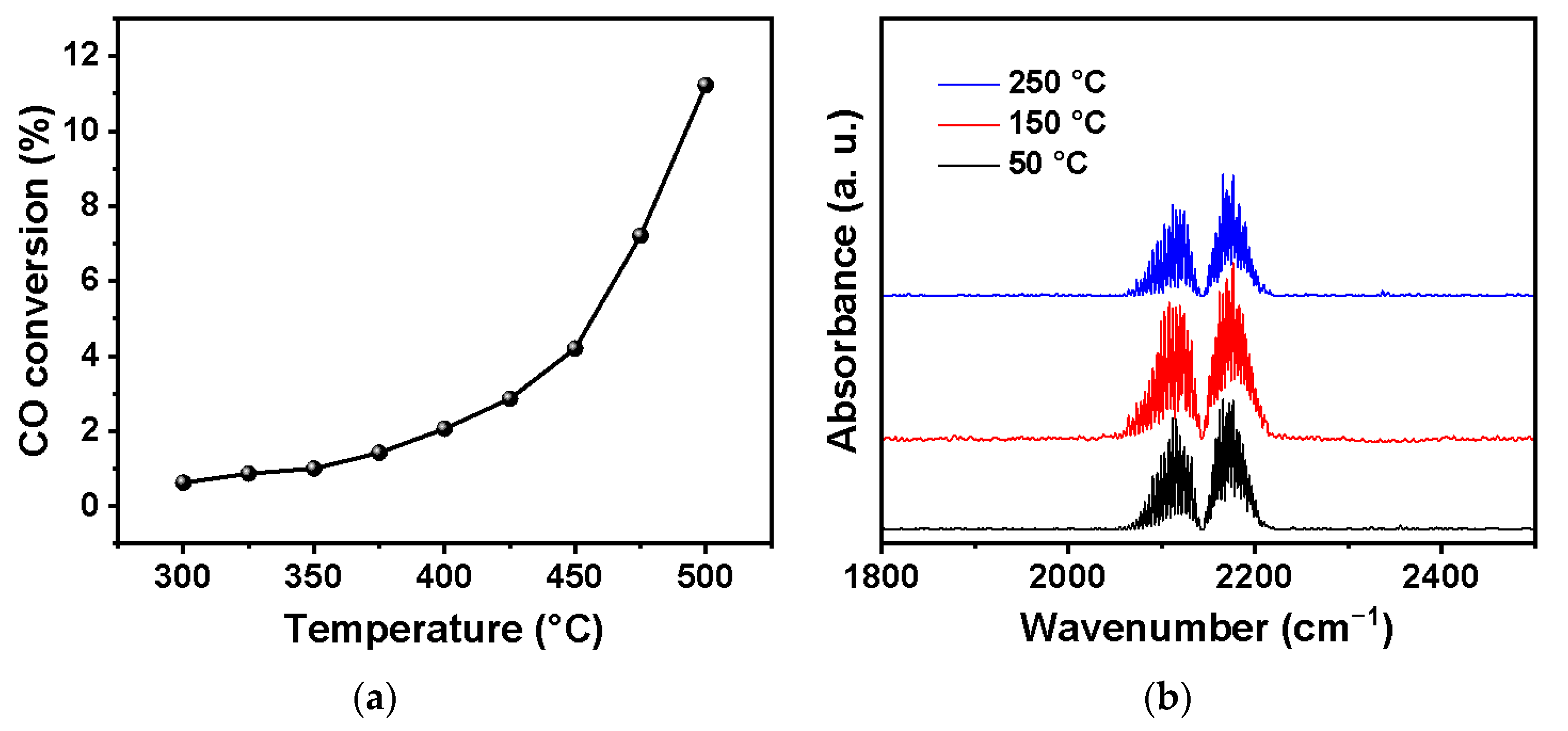
3.1. Catalytic Activity

To clarify the catalytic activity of the YSZ powder, CO was chosen as species for the conversion test. The CO conversion of the YSZ powder is shown in Figure 5a. The reaction started to occur when the temperature reached around 300 °C, but the CO conversion is nearly negatable. Approximately 12% of CO was oxidized to CO2 at 500 °C, indicating that YSZ has a poor catalytic activity towards CO oxidation at low temperature. The in-situ DRIFTS was conducted for a YSZ-coated substrate to study the adsorption and conversion of CO. The spectra were collected at 50, 150, and 250 °C, which is shown in Figure 5b). The rotational−vibrational CO bands are observed at 2113 cm−1 (center of P-branch) and 2173 cm−1 (center of R-branch), attributed to the co-adsorption of the gas-phase and linearly adsorbed CO on the YSZ surface [19]. There is no significant change for the peak intensities with increasing temperature, while no peak was observed in the range of 2300 to 2400 cm−1, which could be assigned to CO2 [26], indicating that YSZ-coated substrate has no significant catalytic activity towards CO oxidation up to 250 °C.

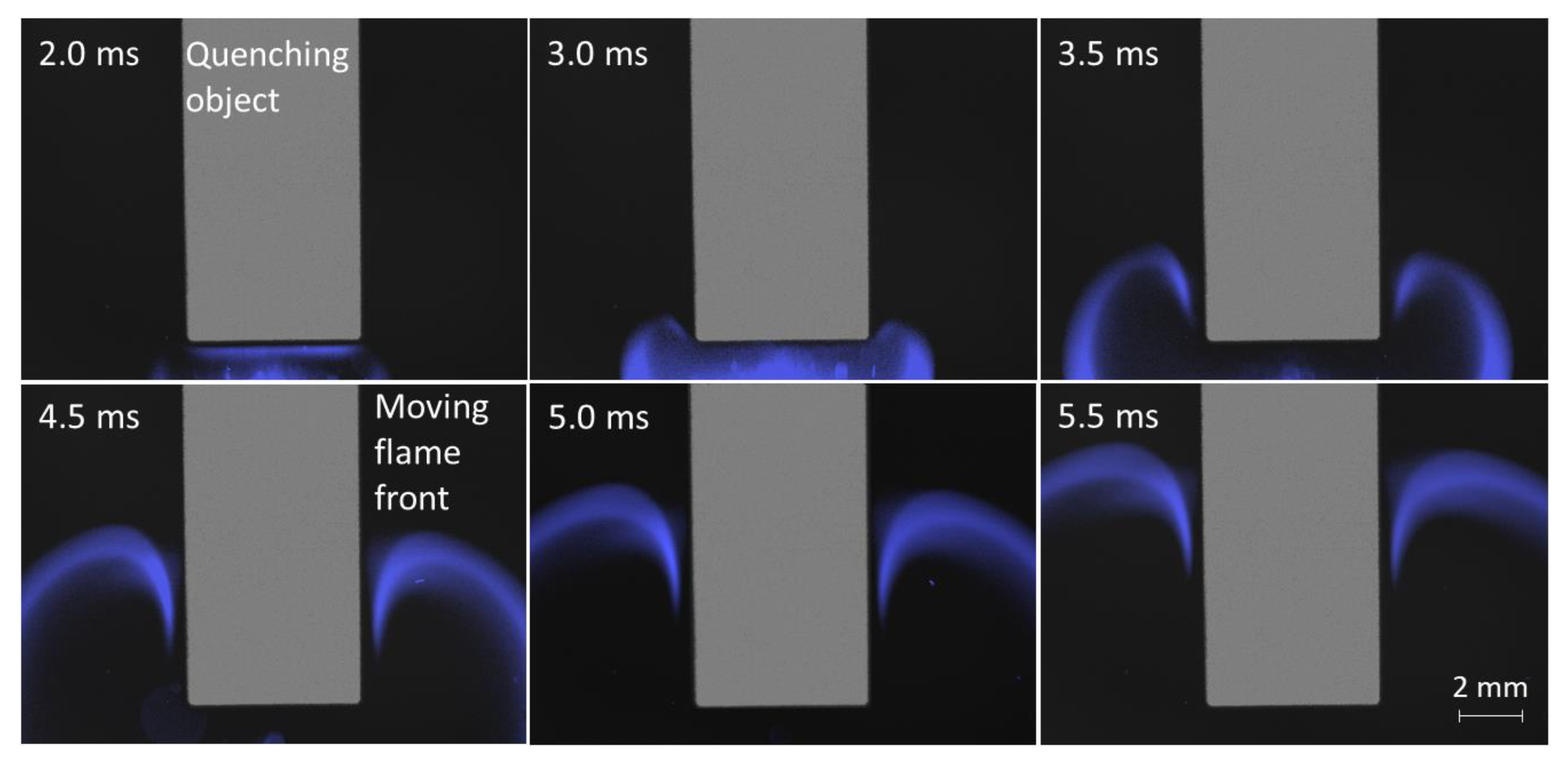
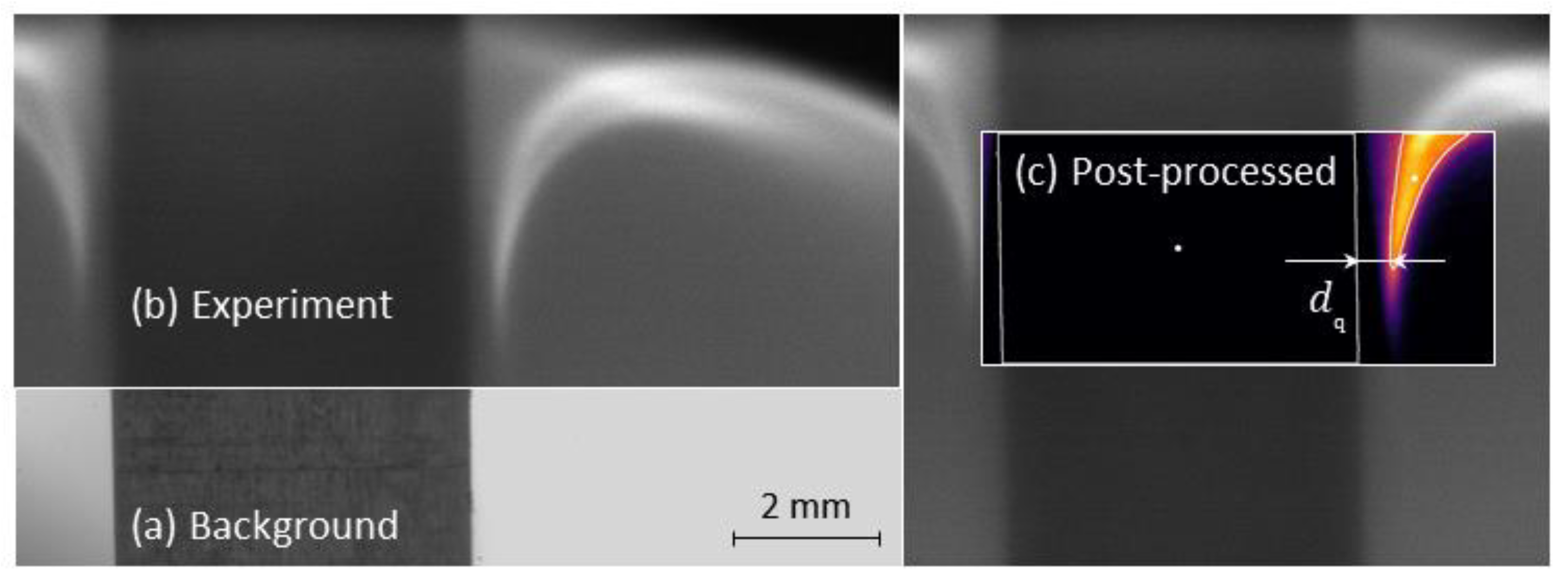
3.2. Flame Quenching

The measured quenching distances dq are shown in Figure 6a at two different gas/wall temperatures of 20 °C and 200 °C. In Figure 6b, the Péclet numbers for the averaged quenching distances of the different cases have been calculated with the definition of
Pé = dq/df
and
df = λ/(su⋅cp⋅ρ)
where df is the flame thickness, su the laminar flame speed, λ the thermal conductivity, cp the heat capacity, and ρ the density. The Péclet number is hereby a non-dimensional quenching distance that can be used to give a rough approximation of the physical quenching distance at other conditions than the investigated one [17,37]. For the simulation of the laminar flame speed, the Gri3.0 mechanism [38] and the Cantera software package have been used [39]. The measurements have been conducted at a pressure of 0.63 bar with an initial pressure of 0.60 bar. The standard deviation of the measurement series reached from 6.6 µm to 11.7 µm. For the 20 °C case, the average quenching distance of the uncoated object was 0.469 mm, while the coated object showed an average quenching distance of 0.422 mm (−10.0%). At 200 °C, the quenching distance of the uncoated case was determined at 0.387 mm and at 0.365 mm for the YSZ-coated case (−5.6%). A decrease of the coating effect with increasing wall temperature was expected as the flame becomes less sensitive to thermal quenching at higher wall temperatures. Furthermore, it has to be noted that the quenching distance reduction by the wall temperature (−13.5%) was more significant than by the YSZ coating (−5.6%).
To estimate the impact of this coating at engine-relevant conditions, a constant Péclet number over pressure [25] was assumed for the case of 20 bar and 200 °C. This would lead to a quenching distance of 34 µm for the uncoated wall and to 32 µm for the YSZ-coated wall. The achieved reduction would only be 2 µm (−5.6%), which takes into account only the reduction by the changed thermal properties for the same wall temperature. Nevertheless, it should be noted that this rough estimation excludes engine effects such as the thermal swing during compression phase for which the coating was designed. This effect could lead to temporally much higher wall temperatures due to the coating. This would then strongly decrease the quenching distance, as it was shown that the wall temperature has a stronger reduction effect (−13.5%) than the insulation effect (−5.6%). In summary, a positive effect of the coating on the flame quenching was observed at low and high temperatures, but its impact on the engine process cannot be fully assessed by this method. Therefore, more advanced measurement techniques are necessary, such as rapid sampling.

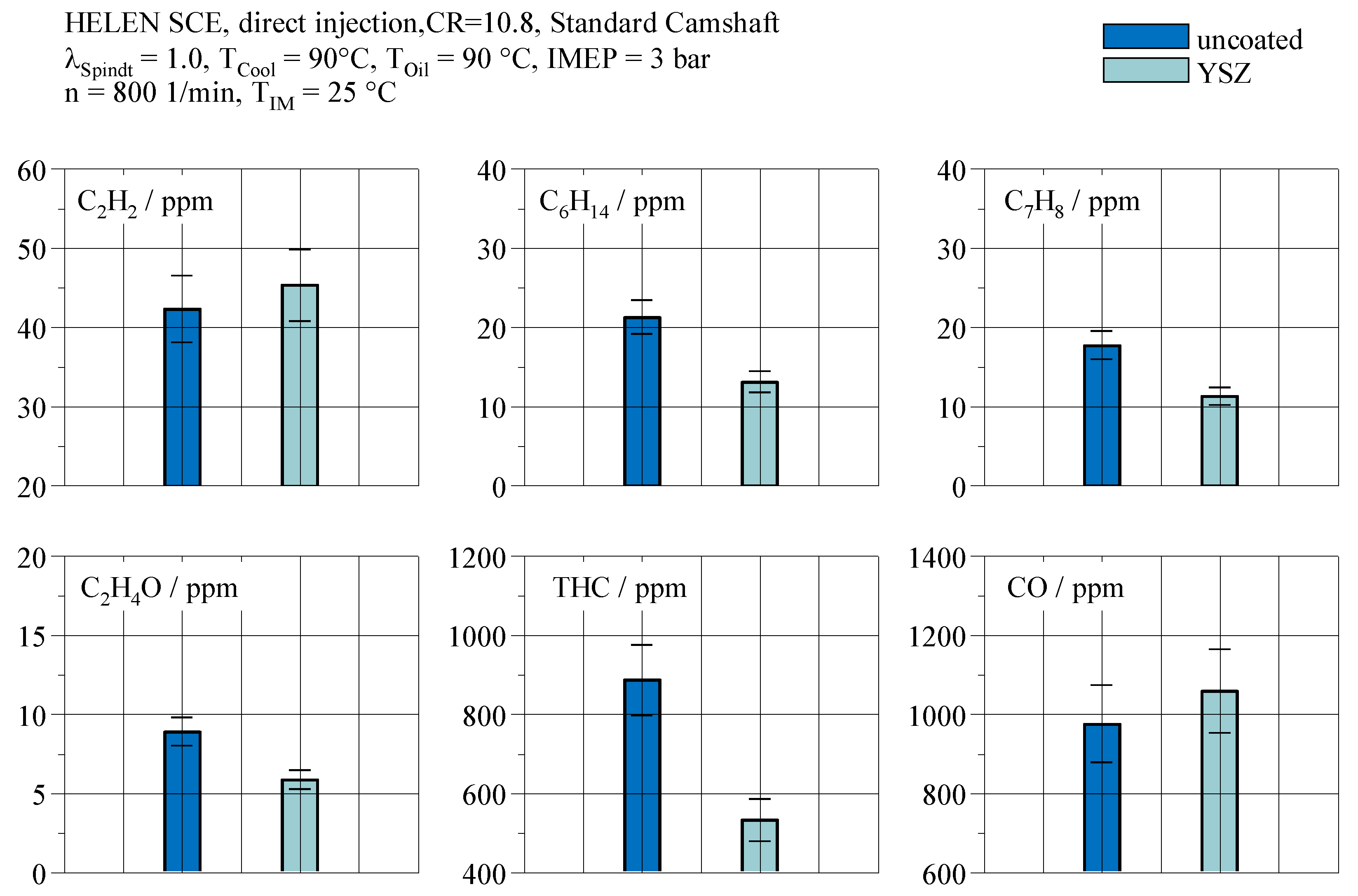
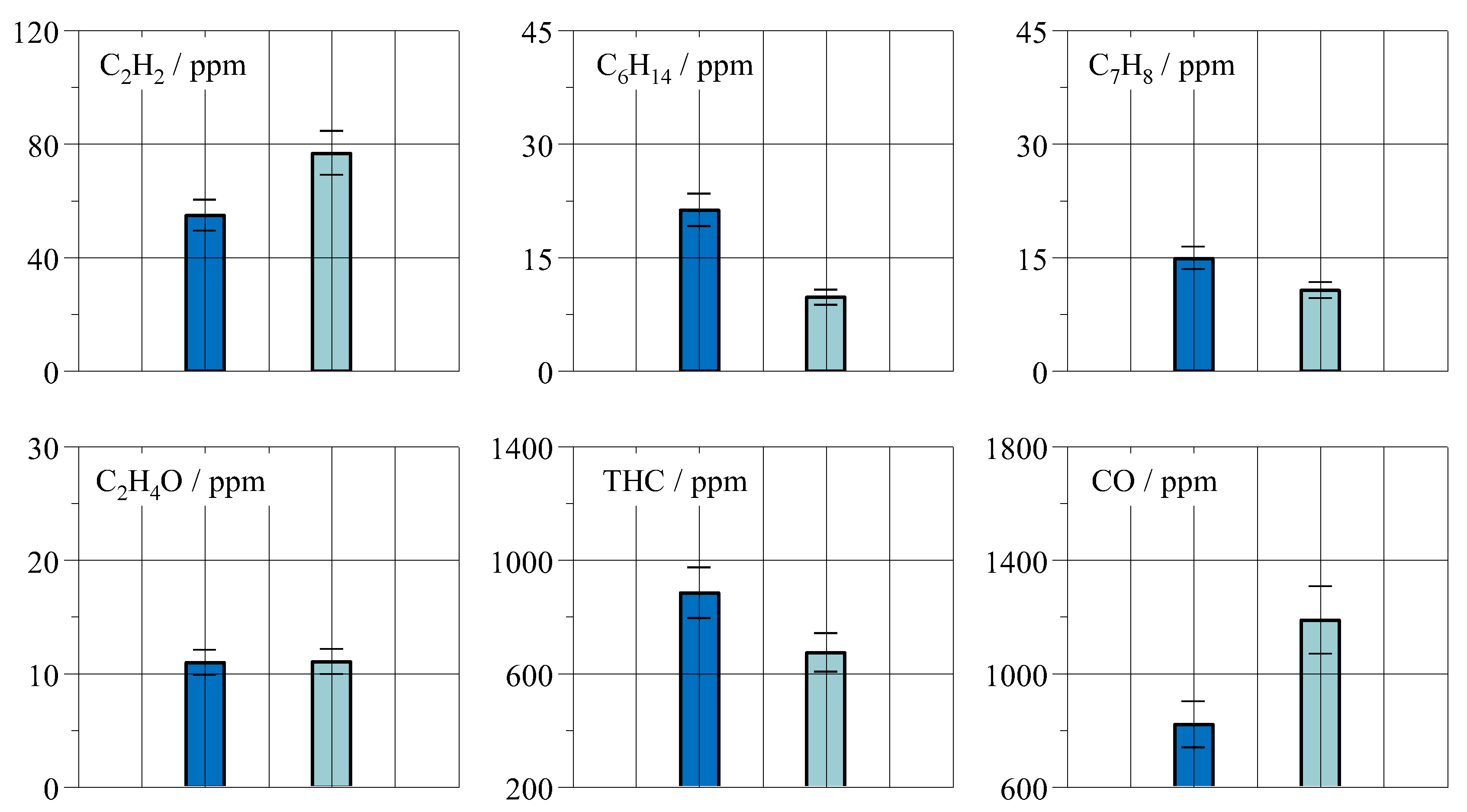
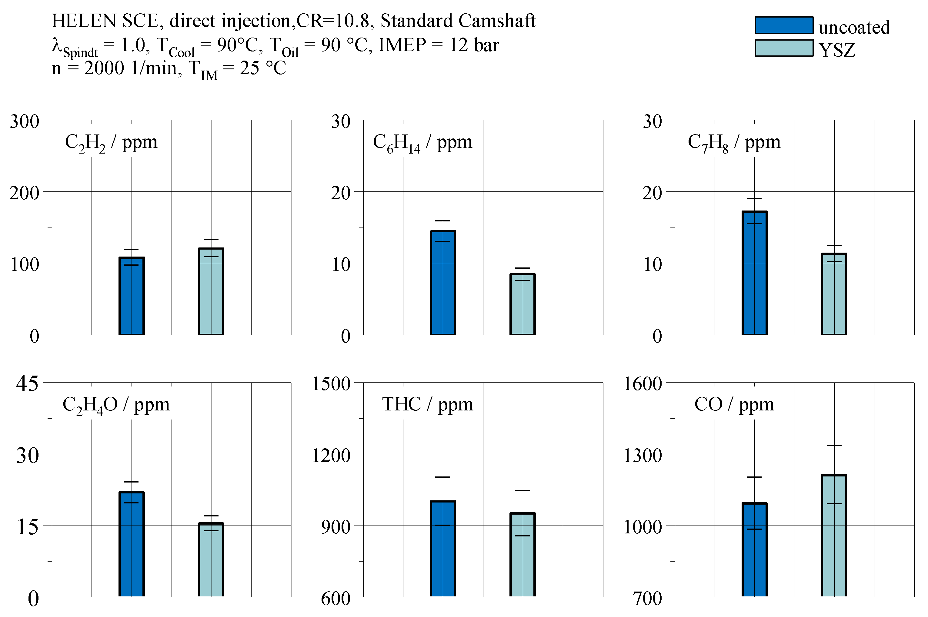
3.3. Near-Wall Gas Composition

The near-wall gas composition was studied at three different engine load points in order to vary the in-cylinder temperature and pressure, and observe the influence of the YSZ coating.
Figure 7 shows the measured species concentration from the sample for an engine speed of n = 800 1/min and an indicated mean effective pressure of IMEP = 3 bar, which corresponds to a near idle engine operating condition. Displayed are both cases, the uncoated and YSZ-coated case, for different hydrocarbon species, the total amount of hydrocarbons (THC), and carbon monoxide (CO). The measurement uncertainty is indicated with the error bars. The species concentration for hexane C6H14 and Toluene C7H8 can be significantly reduced by 38.38% (C6H14) and by 36.39% (C7H8) due to the presence of the YSZ coating. These hydrocarbons are part of the fuel the engine is operated on. This leads to the conclusion that the quenching layer from where these emissions originate is reduced by the YSZ coating compared to the uncoated case. This can be confirmed by the overall hydrocarbon emissions (THC) which are calculated from the measured hydrocarbon species concentrations by the FTIR. The THC concentration is reduced by 39.88% with the YSZ coating. Further, a significant effect on the unsaturated hydrocarbons such as acetylene C2H2 cannot be observed since it is within the measurement uncertainty. Nevertheless, the slight increase visible could be caused by the higher gas temperature in front of the flame due to the higher wall temperature with the applied coating.
The carbon monoxide emissions are slightly increased for the YSZ coating, although the change is within the measurement uncertainty. This could result from the reduced quenching distance and accordingly a larger burned gas fraction. In conclusion, the carbon monoxide emissions slightly increase since they originate from partial combustion due to locally rich or wide lean relative air/fuel ratio or flame extinctions due to strain [40]. Furthermore, for a larger burned gas zone, higher carbon dioxide concentration will be observed in the sample. Carbon dioxide and carbon monoxide are in an equilibrium in the burned zone, and, accordingly, higher carbon dioxide concentration will lead to increased carbon monoxide concentration in the sample. Additionally, the equilibrium will shift towards higher carbon monoxide production for increased temperatures [41]. Figure 8 shows the same species concentrations but at higher engine speeds compared to Figure 7. Evaluating the emissions at the same engine load but higher engine speed shows roughly the same effects of the coating on the fuel hydrocarbons as for the near-idle engine speed. Nevertheless, the higher engine speed leads to higher in-cylinder temperatures due to higher cylinder wall temperatures and accordingly lower heat losses, which accelerate the combustion. Therefore, the relative reduction of the respective species is slightly smaller than for the idle-speed case. Furthermore, the quenching distance is already reduced for the uncoated case compared to lower engine speeds. Therefore, the relative effect of the YSZ coating on the quenching distance and the hydrocarbon species concentration is reduced.
Figure 9 shows the species concentration of the sample at a higher engine load of IMEP = 12 bar compared to Figure 8. It can be observed that at higher engine loads, the reduction of the total hydrocarbon emissions is significantly smaller for an indicated mean effective pressure of IMEP = 12 bar compared to IMEP = 3 bar. This results from the higher in-cylinder pressures and temperatures at higher engine loads due to the resulting higher flame power which results in reduced quenching distances [27]. A slight influence on the saturated and total hydrocarbons can still be observed, but this reduction is inside of the measurement uncertainty, especially for the total hydrocarbons. Therefore, a definite statement regarding this point cannot be given.

4. Conclusions

An yttria-stabilized zirconia coating was investigated regarding its influence on the flame quenching and the near-wall gas composition. Therefore, different substrate geometries were coated by atmospheric plasma spraying enabling a robust and porous coating layer. It was observed that:
  • YSZ shows no significant catalytic activity, and, accordingly, the observed effects regarding the gas composition are deemed to result from the flame quenching at the wall.
  • Flame quenching distance is reduced when applying a YSZ layer by 10.0% at ambient conditions and 5.6% at 200 °C in the CVCC measurements.
  • Near-wall gas composition shows significantly lower total hydrocarbon emissions if the YSZ coating is applied near idle engine operation, which seems to be related to the lower quenching distance when the YSZ layer is applied.
  • Increased engine speed and load still showed reduced total hydrocarbon emissions, but of significant lower amount due to the higher in-cylinder temperatures and pressures at these operating conditions.
  • Saturated hydrocarbons such as C6H14 become reduced, which aligns with the lower quenching distance.
  • Hydrocarbons such as C2H2 and C2H4O are partially increased or decreased, indicating a partial oxidation of these species in the unburned zones due to the higher wall and accordingly gas temperatures, but changes are within measurement uncertainty.
Finally, it can be concluded that dedicated designed thermal swing coatings such as the investigated YSZ can reduce the quenching distance in internal combustion engines and accordingly the local total hydrocarbon concentration. Future investigations will also aim to evaluate the effect of catalytic coatings on the flame-wall interaction and the near-wall gas composition. Thereby, a combination with thermal swing coatings is contemplated to achieve the light-off temperature of the catalytic material.

Author Contributions

Conceptualization, K.A.H., S.P. and U.S.; methodology, M.F., A.N., X.W., D.Z. and R.V.; software, M.F., A.N. and X.W.; validation, M.F., A.N. and X.W.; formal analysis, M.F., A.N., X.W. and D.Z.; investigation, M.F., A.N., X.W. and D.Z.; resources, K.A.H., S.P., R.V. and U.S.; data curation, M.F., A.N., X.W. and D.Z.; writing—original draft preparation, M.F.; writing—review and editing, M.F., A.N., X.W. and D.Z.; visualization, M.F., A.N., X.W. and D.Z.; supervision, K.A.H., S.P., R.V. and U.S.; project administration, K.A.H., S.P., R.V. and U.S.; funding acquisition, K.A.H., S.P., R.V. and U.S. All authors have read and agreed to the published version of the manuscript.

Funding

The authors gratefully acknowledge the funding by the Deutsche Forschungsgemein-schaft (DFG, German Research Foundation) under Germany’s Excellence Strategy—Cluster of Excellence 2186 “The Fuel Science Center”, ID: 390919832.

Data Availability Statement

The data presented in this study are available on request from the corresponding author.

Conflicts of Interest

The authors declare no conflict of interest.

References

  1. Samaras, Z.C.; Kontses, A.; Dimaratos, A.; Kontses, D.; Balazs, A.; Hausberger, S.; Ntziachristos, L.; Andersson, J.; Ligterink, N.; Aakko-Saksa, P.; et al. A European Regulatory Perspective towards a Euro 7 Proposal; SAE Technical Paper Series; SAE International: Warrendale, PA, USA, 2022. [Google Scholar]
  2. Achenbach, J.; Fischer, M.; Lehrheuer, B.; Guenther, M.; Pischinger, S. Influence of thermal piston insulation on the indicated efficiency of SI-engines. In Proceedings of the COMODIA2022: 10th International Conference on Modeling and Diagnostics for Advanced Engine Systems, Sapporo, Japan, 5–8 July 2022. [Google Scholar]
  3. Hasse, C.; Bollig, M.; Peters, N.; Dwyer, H. Quenching of laminar iso-octane flames at cold walls. Combust. Flame 2000, 122, 117–129. [Google Scholar] [CrossRef]
  4. Memme, S.; Wallace, J.S. The Influence of Thermal Barrier Coating Surface Roughness on Spark-Ignition Engine Performance and Emissions. In Proceedings of the ASME 2012 Internal Combustion Engine Division Fall Technical Conference, Vancouver, BC, Canada, 23–26 September 2012; pp. 893–905. [Google Scholar]
  5. Büyükkaya, E.; Engin, T.; Cerit, M. Effects of thermal barrier coating on gas emissions and performance of a LHR engine with different injection timings and valve adjustments. Energy Convers. Manag. 2006, 47, 1298–1310. [Google Scholar] [CrossRef]
  6. Andrie, M.; Kokjohn, S.; Paliwal, S.; Kamo, L.S.; Kamo, A.; Procknow, D. Low Heat Capacitance Thermal Barrier Coatings for Internal Combustion Engines; SAE Technical Paper Series; SAE International: Warrendale, PA, USA, 2019. [Google Scholar]
  7. Chan, S.H.; Khor, K. The Effect of Thermal Barrier Coated Piston Crown on Engine Characteristics. J. Mater. Eng. Perform. 2000, 9, 103–109. [Google Scholar] [CrossRef]
  8. de Goes, W.U.; Markocsan, N.; Gupta, M.; Vaßen, R.; Matsushita, T.; Illkova, K. Thermal barrier coatings with novel architectures for diesel engine applications. Surf. Coat. Technol. 2020, 396, 125950. [Google Scholar] [CrossRef]
  9. Uchida, N. A review of thermal barrier coatings for improvement in thermal efficiency of both gasoline and diesel reciprocating engines. Int. J. Engine Res. 2020, 23, 3–19. [Google Scholar] [CrossRef]
  10. Babu, A.; Koutsakis, G.; Kokjohn, S.; Andrie, M. Experimental and Analytical Study of Temperature Swing Piston Coatings in a Medium-Duty Diesel Engine. SAE Int. J. Adv. Curr. Pract. Mobil. 2022, 5, 235–248. [Google Scholar]
  11. Uczak de Goes, W.; Markocsan, N.; Gupta, M. Thermal Swing Evaluation of Thermal Spray Coatings for Internal Combustion Engines. Coatings 2022, 12, 830. [Google Scholar] [CrossRef]
  12. Dhomne, S.; Mahalle, A.M. Thermal barrier coating materials for SI engine. J. Mater. Res. Technol. 2019, 8, 1532–1537. [Google Scholar] [CrossRef]
  13. Vaßen, R.; Mack, D.E.; Tandler, M.; Sohn, Y.J.; Sebold, D.; Guillon, O. Unique performance of thermal barrier coatings made of yttria-stabilized zirconia at extreme temperatures (>1500 °C). J. Am. Ceram. Soc. 2020, 104, 463–471. [Google Scholar] [CrossRef]
  14. Chen, L.B. Yttria-Stabilized Zirconia Thermal Barrier Coatings—A Review. Surf. Rev. Lett. 2006, 13, 535–544. [Google Scholar] [CrossRef]
  15. Bobzin, K.; Lugscheider, E.; Bagcivan, N. Thermal cycling behavior of Yttria Stabilized Zirconia and Lanthanum Zirconate as graded and bilayer EB-PVD thermal barrier coatings. High Temp. Mater. Process. Int. Q. High-Technol. Plasma Process. 2006, 10, 103–116. [Google Scholar] [CrossRef]
  16. Planques, P.; Vidal, V.; Lours, P.; Proton, V.; Crabos, F.; Huez, J.; Viguier, B. Mechanical properties of yttria-stabilised-zirconia for thermal barrier coating systems: Effects of testing procedure and thermal aging. In Proceedings of the 2017 IEEE 20th International Conference on Intelligent Transportation Systems (ITSC), Dusseldorf, Germany, 7–9 June 2017; pp. 302–307. [Google Scholar]
  17. Häber, T.; Suntz, R. Effect of different wall materials and thermal-barrier coatings on the flame-wall interaction of laminar premixed methane and propane flames. Int. J. Heat Fluid Flow 2018, 69, 95–105. [Google Scholar] [CrossRef]
  18. Sivakumar, G.; Kumar, S.S. Investigation on effect of Yttria Stabilized Zirconia coated piston crown on performance and emission characteristics of a diesel engine. Alex. Eng. J. 2014, 53, 787–794. [Google Scholar] [CrossRef] [Green Version]
  19. Powell, T.; O’Donnell, R.; Hoffman, M.; Filipi, Z. Impact of a Yttria-Stabilized Zirconia Thermal Barrier Coating on HCCI Engine Combustion, Emissions, and Efficiency. J. Eng. Gas Turbines Power 2017, 139, 111504. [Google Scholar] [CrossRef] [Green Version]
  20. Powell, T.; O’Donnell, R.; Hoffman, M.; Filipi, Z.; Jordan, E.H.; Kumar, R.; Killingsworth, N.J. Experimental investigation of the relationship between thermal barrier coating structured porosity and homogeneous charge compression ignition engine combustion. Int. J. Engine Res. 2021, 22, 88–108. [Google Scholar] [CrossRef]
  21. Lorenzo-Bañuelos, M.; Díaz, A.; Rodríguez, D.; Cuesta, I.; Fernández, A.; Alegre, J. Influence of Atmospheric Plasma Spray Parameters (APS) on the Mechanical Properties of Ni-Al Coatings on Aluminum Alloy Substrate. Metals 2021, 11, 612. [Google Scholar] [CrossRef]
  22. Vaßen, R.; Jarligo, M.O.; Steinke, T.; Mack, D.E.; Stöver, D. Overview on advanced thermal barrier coatings. Surf. Coat. Technol. 2010, 205, 938–942. [Google Scholar] [CrossRef]
  23. Zhang, L.-C.; Jia, Z.; Lyu, F.; Liang, S.-X.; Lu, J. A review of catalytic performance of metallic glasses in wastewater treatment: Recent progress and prospects. Prog. Mater. Sci. 2019, 105, 100576. [Google Scholar] [CrossRef]
  24. Rizzotto, V.; Chen, D.; Tabak, B.M.; Yang, J.Y.; Ye, D.; Simon, U.; Chen, P. Spectroscopic identification and catalytic relevance of NH4+ intermediates in selective NOx reduction over Cu-SSZ-13 zeolites. Chemosphere 2020, 250, 126272. [Google Scholar] [CrossRef]
  25. Wu, X.; Fischer, M.; Nolte, A.; Lenßen, P.; Wang, B.; Ohlerth, T.; Wöll, D.; Heufer, K.A.; Pischinger, S.; Simon, U. Perovskite Catalyst for In-Cylinder Coating to Reduce Raw Pollutant Emissions of Internal Combustion Engines. ACS Omega 2022, 7, 5340–5349. [Google Scholar] [CrossRef]
  26. Bellenoue, M.; Kageyama, T.; Labuda, S.; Sotton, J. Direct measurement of laminar flame quenching distance in a closed vessel. Exp. Therm. Fluid Sci. 2003, 27, 323–331. [Google Scholar] [CrossRef]
  27. Boust, B.; Sotton, J.; Labuda, S.; Bellenoue, M. A thermal formulation for single-wall quenching of transient laminar flames. Combust. Flame 2007, 149, 286–294. [Google Scholar] [CrossRef]
  28. Bradski, G.; Kaehler, A. OpenCV. Dr. Dobbs J. Softw. Tools 2000, 3. [Google Scholar]
  29. Fischer, M.; Lehrheuer, B.; Pischinger, S. Evaluation of the near-wall gas composition in SI-engines using fast gas sampling. Int. J. Engine Res. 2023, 14680874221149603. [Google Scholar] [CrossRef]
  30. Yücel, N.; Karaaslan, S.; Ender, H.; Dinler, N. High Speed Gas Sampling System for Engine Cylinder Emission Analyses. JOCET 2013, 1, 144–147. [Google Scholar] [CrossRef] [Green Version]
  31. Talibi, M.; Hellier, P.; Balachandran, R.; Ladommatos, N. Development of a Fast-Acting, Time-Resolved Gas Sampling System for Combustion and Fuels Analysis. SAE Int. J. Engines 2016, 9, 1102–1116. [Google Scholar] [CrossRef]
  32. Dell, R.M.; Moseley, P.T.; Rand, D.A. Chapter 4—Development of Road Vehicles with Internal-Combustion Engines. In Towards Sustainable Road Transport; Dell, R.M., Moseley, P.T., Rand, D.A.J., Eds.; Academic Press: Boston, MA, USA, 2014; pp. 109–156. [Google Scholar]
  33. Wouters, C.; Burkardt, P.; Fischer, M.; Blomberg, M.; Pischinger, S. Effects of stroke on spark-ignition combustion with gasoline and methanol. Int. J. Engine Res. 2021, 23, 804–815. [Google Scholar] [CrossRef]
  34. De Hoffmann, E.; Stroobant, V. Mass Spectrometry: Principles and Applications; Wiley: Chichester, UK; Hoboken, NJ, USA, 2007. [Google Scholar]
  35. Akashi, K.; Inoue, K.; Adachi, M.; Ishida, K.; Villinger, J.; Federer, W.; Dornauer, A. Utilization of a Soft Ionization Mass Spectrometer for Ultra High Sensitivity and Fast Response Emission Measurements. SAE J. Fuels Lubr. 1998, 107, 13–23. [Google Scholar]
  36. Villinger, J.; Federer, W.; Dornauer, A.; Weissnicht, A.; Hönig, M.; Mayr, T. Dynamic Monitoring of Differentiated Hydrocarbons in Direct Engine Exhaust: A Versatile Tool in Engine Development. SAE Int. J. Engines 1996, 105, 172–179. [Google Scholar]
  37. Poinsot, T.J.; Haworth, D.C.; Bruneaux, G. Direct Simulation and Modeling of Flame-Wall Interaction for Pre-mixed Turbulent Combustion. Combust. Flame 1993, 95, 118–132. [Google Scholar] [CrossRef]
  38. Smith, G.P.; Golden, D.M.; Frenklach, M.; Moriarty, N.W.; Eiteneer, B.; Goldenberg, M.; Bowman, C.T.; Hanson, R.K.; Song, S.; Gardiner, W.C.; et al. Gri3.0. 2021. Available online: http://www.me.berkeley.edu/gri_mech/ (accessed on 23 March 2021).
  39. Goodwin, D.G.; Moffat, H.K.; Speth, R.L. Cantera: An Object-Oriented Software Toolkit for Chemical Kinetics, Thermodynamics, and Transport Processes, version 2.2. 1; Cantera Developers: Warrenville, IL, USA, 2021. [Google Scholar]
  40. Heywood, J.B. Internal combustion engine fundamentals. Edição Estados Unidos 1988, 25, 1117–1128. [Google Scholar]
  41. Glarborg, P.; Bentzen, L.L.B. Chemical Effects of a High CO2 Concentration in Oxy-Fuel Combustion of Methane. Energy Fuels 2007, 22, 291–296. [Google Scholar] [CrossRef]
Figure 1. Piston surface temperature and piston heat transfer with and without thermal swing coating [2].
Energies 16 02872 g001
Figure 2. Cross-sectional microstructure (A) and surface morphology (B) of the as-sprayed YSZ coating.
Energies 16 02872 g002
Figure 3. Transition from head-on quenching to sidewall quenching with an intensity offset of 60% maximum intensity.
Energies 16 02872 g003
Figure 4. Schematic of the post-processing to assess the quenching distance. (a) Bright background image of the quenching object. (b) Image of the sidewall flame quenching during the experiment. (c) Post-processed image with marked object and flame contours by white lines.
Energies 16 02872 g004
Figure 5. (a) CO conversion of YSZ powder with the gas flow of 0.5% CO, 10% O2, and balance N2. (b) In-situ DRIFTS spectra of YSZ-coated substrate at different temperatures with the same gas flow.
Energies 16 02872 g005
Figure 6. (a) Measured sidewall quenching distances for a propane/air mixture (Φ = 1.2) at 0.63 bar. (b) Derived Péclet numbers.
Energies 16 02872 g006
Figure 7. Measured species of near-wall gas sample of the GSV at n = 800 1/min and IMEP = 3 bar.
Energies 16 02872 g007
Figure 8. Measured species of near-wall gas sample of the GSV at n = 2000 1/min and IMEP = 3 bar.
Energies 16 02872 g008
Figure 9. Measured species of near-wall gas sample of the GSV at n = 2000 1/min and IMEP = 12 bar.
Energies 16 02872 g009
Table 1. Detailed spraying parameters of the plasma-sprayed YSZ coating.
ParameterValue
Current [A]350
Spraying distance [mm]187
Plasma gas composition 46 SLPM Ar
4 SLPM He
Robot speed (mm/s)1000
Spraying cycles280
Cooling gas (bar)4
Table 2. Single cylinder engine specifications.
Stroke [mm]113.2
Bore [mm]75
Swept volume [cm3]500
Pressure intake manifold [bar]Max. 3.5
Stroke-to-bore ratio [-]1.5
Injection pressure [bar]200
Compression ratio [-]10.8
Disclaimer/Publisher’s Note: The statements, opinions and data contained in all publications are solely those of the individual author(s) and contributor(s) and not of MDPI and/or the editor(s). MDPI and/or the editor(s) disclaim responsibility for any injury to people or property resulting from any ideas, methods, instructions or products referred to in the content.

