
Research on Deformation of Hydraulic Cylinders Made of Plastics
Mechanical Engineering Faculty, Wroclaw University of Science and Technology, 50-370 Wrocław, Poland
Energies 2023, 16(15), 5708; https://doi.org/10.3390/en16155708
Submission received: 29 June 2023
/
Revised: 16 July 2023
/
Accepted: 19 July 2023
/
Published: 31 July 2023
(This article belongs to the Special Issue Application and Analysis in Fluid Power Systems II)
Abstract
:The article presents an author’s approach to the study of the behavior of plastic hydraulic cylinder structures under load. Plastics as design materials, due to their different properties, behave differently from metals. So far, there is little information about hydraulic cylinders made of plastics. They are a technical novelty, and there are no established standards or research methods for them. The tests were carried out on the example of two models of different internal diameter, the smaller one being Ø30 mm and the larger one Ø50 mm. Information was gathered by FEM simulation tests and tests of real models on a special test stand. The simulation section presents geometric models, discrete models and assumed boundary conditions, as well as the results of the performed simulations. For tests of real models, a description of the stand with the measuring equipment used is presented, e.g., laser displacement sensors, as well as the method of conducting the tests and the results. Then, the results are analyzed and compared. Deformations of the examined structures are discussed, e.g., tube swelling or deflection, which seem to be characteristic for plastic cylinders. Finally, the possibility of using selected plastics for the design material of hydraulic cylinders and the suitability of the research method used are assessed.
1. Introduction
Metal hydraulic cylinders are among the largest and heaviest components in hydraulic systems. Loads which they exert on machine structures are significant. An important scientific and technical task is to reduce the mass of cylinders while maintaining the highest possible technical parameters. This is achieved by designing cylinders of composites. An overview of the possibilities of using composites for the construction of hydraulic cylinders is presented in [1] and a review of development of composite hydraulic actuators in [2]. Most design solutions use a steel or aluminum pipe with small wall thickness, which is surrounded by a composite layer in order to increase its strength.
In papers [3,4], design and experimental tests of composite cylinders are presented. A very important stage in the process of designing and manufacturing composite cylinders is manufacturing of coatings on tubes, which is presented in [5].
An alternative direction in the development of non-metallic cylinders is designing cylinders, in which the main elements such as the cylinder tube, piston or caps are made of plastic materials without composite additives. Therefore, new design and research challenges arise. In this case, the fundamental task is to develop a special method for designing plastic cylinders. Such a method was presented in [6].
In this method, it was shown that the choice of plastic material has an impact on the design, manufacturing technology, exploitation and application areas of cylinders made of plastics. This is due to the lower strength and greater elasticity of plastic compared to metal materials [7]. Less strength and greater elasticity leads to greater deformations. This was also confirmed in the case of such hydraulic elements made of plastics like gerotor pumps [8,9,10] or valves [11].
In the case of cylinders, local deformations and global deformations of the entire cylinder structure can be distinguished, which include the extended piston rod.
Local deformations are unfavorable because they can lead to a loss of tightness between the sleeve and the piston and, as a result, decrease the efficiency ɳ and drop of the working pressure p.
On the other hand, global deformations can lead to loss of cylinder stability and buckling.
Both types of deformations are related to the geometry of the cylinder and its overall dimensions, especially the diameter D, the stroke S and the length L, which is connected to stroke. Research on the behavior of the structures of plastic hydraulic cylinders is therefore an important step in verifying their function and the prediction of their technical parameters.
The standard procedures recommended by ISO are not sufficient because they do not provide outlines for simulations or experimental deformation tests. Therefore, the aim of the work was to perform tests for cylinders made of plastics, including:
- -
- Computer simulations of stress and strain carried out using FEM;
- -
- Experimental research of deformations using a special test stand.
The method and the scope of these tests may be used as a research path in the process of designing plastic cylinders.
2. Computer Simulations Using FEM
2.1. Objects of Research and Their Models
The object of the tests are two cylinders made of plastics, designed according to method [12]. These are the cylinders:
- -
- The smaller cylinder with a diameter Ø = 30 mm and a stroke S = 200 mm designed for small-sized systems and nominal working pressure p = 6.3 MPa;
- -
- The larger cylinder with a diameter Ø = 50 mm and a stroke S = 200 mm intended for medium-sized systems (mass) and nominal working pressure p = 6.3 MPa.
The tubes, pistons and cylinder caps are made of polyoxymethylene (POM), while the piston rods and tie rods are made of steel. It is assumed that the plastic as a design material works within the range defined by the elastic limit Re0.2, which in the case of polyoxymethylene is Re0.2 = 60 MPa. Taking into account the possibility of temperature influence and the of hysteresis of deformations, the limit of permissible plastic stresses is lowered and determined in accordance with the principle shown in [12], which is shown in Equation (1).
According to the rules of FEM given in [13,14], for each of these cylinders, a set of models was developed for the simulation process, i.e., a geometric model, a discrete model and a model of restraints and loads. An exemplary set of models for a cylinder of diameter Ø = 30 mm is shown in Figure 1.
The geometric model—Figure 1a—was developed on the basis of design documentation in accordance with the method [12]. Then, this model was discretized by applying a finite element mesh, as shown in Figure 1b. Hexahedral elements with the designation C3D8R were used, creating a mesh of 161,740 elements and 194,069 nodes. Then, the model of restraints shown in Figure 1c were established. Three places were fixed, i.e., in the rear cover, in the front cover and at the end of the piston rod. This is a typical situation corresponding to the actual conditions of restraint of cylinders in load-bearing structures of machines and devices. This mounting pattern reduces the possibility of occurrence of buckling and uncontrolled deformations.
The load model shown in Figure 1d consists of:
- -
- Hydraulic loads (1) with working pressure acting on the channels in the bottom cap and the bottom chamber (under-piston chamber) in the cylinder’s tube, or on the channels in the gland cap and the gland chamber (over-piston chamber) in the cylinder’s tube;
- -
- Mechanical loads (2) acting on the piston rod along its axis, in the direction opposite to the movement of piston rod.
The set of loads can be implemented at different phases of the work cycle, i.e., extension or retraction. The placement of the piston changes in both phases of the work cycle, which is taken into account by developing a model for extreme positions (piston not extended S = 0; fully extended S = 1) and an intermediate position (piston partially extended S = 0.5). This set corresponds to the work cycle of the cylinder.
The cylinder was loaded successively with intermediate pressure and nominal pressure, i.e., p = 3; 6.3 MPa.
In the successively considered cases, the stresses σ were determined and compared with the allowable stresses σlim. Displacements (strains) Δ were also determined locally and globally.
For the Ø = 50 mm cylinder, the same rules of creating models and conducting simulations as for the Ø = 30 cylinder were adopted.
2.2. Simulation Results and Discussion
Figure 2 presents maps of stresses (strains) of the Ø = 30 mm cylinder loaded with nominal pressure p = 6.3 MPa and force F = 4.5 kN. This was carried out for three consecutive piston positions, i.e., without extension (S = 0), half extension (S = 0.5) and complete extension (S = 1).
Figure 2a shows that the pressure p = 6.3 MPa loads the bottom cap (3) in the area of the bore and the supply channel, as well as the piston (2) and the initial part of the sleeve (1). At the same time, the piston rod is loaded with the force F = 4.5 kN, which balances the force coming from the pressure. In Figure 2b,c it is shown subsequently that with the increase in piston extension, the bottom (under-piston) chamber enlarges, and the cylinder tube (1) is loaded over larger length.
As a result of loads, stresses appear in the main components of the cylinder, i.e., tube (1), piston (2), caps (3, 4) and tie rods (5). They have similar characteristics for all positions of the piston with one difference, which is that, as the chamber under the piston (bottom chamber) enlarges, stresses appear over a larger length of the cylinder tube (1).
In the case of the retraction phase, the pressure is applied to the gland (top) cap in the area of the bore and the supply channel as well as the piston and the cylinder tube from the side of the gland. The piston rod is loaded with the force F = 2.85 kN, which balances the force coming from the pressure.
Table 1 shows the values of maximum stresses σmax occurring in each element of the cylinder, taking into account all piston positions for both cycles (Figure 2a–d). It can be noticed that the maximum stresses occurring in each element of the cylinder have values lower than the allowable stresses σlim determined for POM, i.e., σmax < σlim. Therefore, it can be expected that the cylinder made of POM material will withstand the applied loads, and the material will work in the elastic range.
The stresses In cylinder elements are accompanied by local deformations in these elements. Considering the local deformations of the cylinder tube, it can be seen in Figure 2b that, with the extension of the piston, the diameter of tube increases with a greater length (swelling of the tube). At the same time, the end of the cylinder tube moves along its axis from the supplying side (shortening of the sleeve). Such a situation occurs during extension stroke from the side of the bottom, in the area of the under-piston chamber and also during retraction stroke but from the side of the gland in the area of the over-piston chamber. Taking into account swelling and shortening of the cylinder tube, local displacements of max. Δ = 0.45 mm are determined.
Local deformations also occur in other elements of the cylinder. The maximum values of local deformations Δmax occurring in individual elements of the cylinder are shown in Table 1.
Using computer simulations, a graph shown in Figure 3a was developed, which presents global displacements Δ along the axis of the Ø = 30 mm cylinder’s tube. The figure shows that the walls of the cylinder tube translocate in the direction perpendicular to its axis, which suggests increase in its diameter. Those displacements have similar values along the entire length of the tube, and they increase with pressure. Displacement values are in range Δ = 0.05 ÷ 0.1 mm. Comparing local and global displacements, it seems that global displacements are smaller, even though they are a sum of local displacements. This was a reason why the mechanism of global deformation formation was analyzed using Figure 4.
A cylinder is fixed in the swivel eye brackets of the rear cover and at the end of the piston rod, which corresponds to a typical case of its assembly in machines and devices. Under loads from the pressure p and the force F, rear and front caps twist toward the inside and squeeze the cylinder tube. In this situation, the cylinder bends “downwards”. At the same time, pressure acts on the tube from the inside causing its walls to deform outside, in the direction transverse to the axis (swelling). By combining both types of displacements, i.e., deflection of the entire structure and deformation of the tube walls, global displacements of the cylinder are obtained.
In the case shown in Figure 3a, the deformation of the cylinder tube walls slightly exceeds the cylinder deflection, and results in global displacements in range Δ = 0.05 ÷ 0.1 mm. The mechanism of formulating global deformation during retraction of the piston is shown in Figure 4b. The caps are pushed outside by the internal pressure, which causes them to twist outwards and deforming the structure in the direction “up”. Also, in this case, the tube swells, and both types of displacement combined are result in global displacements.
The mechanism of deformation for the Ø = 50 mm cylinder is similar to the Ø = 30 mm cylinder, and the values of these deformations, determined on the basis of simulation tests, are shown in Figure 3b.
3. Experimental Research
3.1. Research Stand and Method of Testing
Using the examples of designing of test stands given in [15,16,17,18], a special test stand shown in Figure 5 was prepared.
The tested cylinder Ø = 30 mm was mounted to the rigid frame. Its front and rear caps were attached in a way which allowed to maintain the same restraint conditions as in FEM computer simulations. On the stand, opposite the tested cylinder, a metal cylinder (3) was mounted coaxially to create the load. Rods of both cylinders were joined with each other with a special connector (4). The tested cylinder (2) was powered by the hydraulic system (5) and the loading cylinder (3) by the hydraulic system (6). Through control of the hydraulic systems, the movement and loads of the tested cylinder were realized. Hydraulic parameters were measured using pressure transducers (7, 8) and a flow rate meter. The movement of the piston rod was monitored using a displacement transducer (9) and the force on the piston rod using a sensor located in the connector (4). The stand was equipped with a special, precise system of laser sensors for displacement measurement (10), which were used to measure global displacements in points laid on the surface of the plastic cylinder tube.
Figure 5b shows that the laser sensors are placed in a special holder (11). The holder is attached to the rigid frame of the test stand (1) and has no direct contact with the tested cylinder, the structure of which deforms and, as a result, moves relative to the frame.
Tests of deformation for the Ø = 30 mm cylinder were carried out with the piston and piston rod fully extended (see Figure 2c). The cylinder was loaded with a pressure p ≈ 3 MPa, relatively p ≈ 6.3 MPa and the force F ≈ 2.12 kN, relatively F ≈ 4.45 kN. Measurements of the displacement in four points located along the tube were carried out, and the sensor readings were stored in the computer’s memory. Based on these measurement results, a deformation profile of the cylinder tube was drawn. The tests of the Ø = 50 mm cylinder were carried out according to the same rules.
3.2. Research Results and Discussion
Diagrams of displacements of the Ø = 30 mm cylinder structure are shown in Figure 6a. The upper part of the graph shows the global displacements of the structure measured on the surface of the cylinder tube for pressure p = 3; 6.3 MPa and in the lower part a schematic deformation profile of the tube compared to the non-deformed profile shown in the background. Analyzing the displacement diagrams, it can be noticed that at the ends of the sleeve they take negative values, while in the middle of the sleeve they are close to zero or positive. According to the principles given in Section 2.2 and on the basis of Figure 4a, it can be concluded that the deflection at the ends of the tube is greater than the deformation of its walls (swelling), and, as a result, the global displacements are negative. However, in the middle of the tube, the share of the deformation (swelling) in the global displacements is large enough that, in combination with the deflection, they are compensating, so the global displacements take values close to zero, or they are positive, which in turn means that swelling of the tube outweighs the cylinder structure deflection. Figure 6a also shows that displacements increase with increasing pressure p. A similar analysis was carried out for the Ø = 50 mm cylinder, which is shown in the upper and lower part of Figure 6b. In this case, it can be noted that the displacements along the entire length of the sleeve are positive. This means that the swelling of the tube outweighs the cylinder structure deflection and, as a result, the global displacements are positive. Also, in this case, global displacements increase with increasing pressure p.
Comparing the global displacements in cylinders Ø = 30 mm and Ø = 50 mm (Figure 6a,b), it can be noticed that in cylinder Ø = 30 mm deflection of the structure plays a more significant role than deformation of the tube walls, while in cylinder Ø = 50 mm deflection is less significant than deformations of the walls. This results from the fact that with a similar length L, the Ø = 30 mm cylinder has a smaller diameter and thinner walls of the tube and thus lower bending resistance. The Ø = 50 mm cylinder has a similar length of the tube but with thicker walls, which are more distant from its axis. This is why it has greater bending resistance, and, as a result, the global deformations of the walls take positive values.
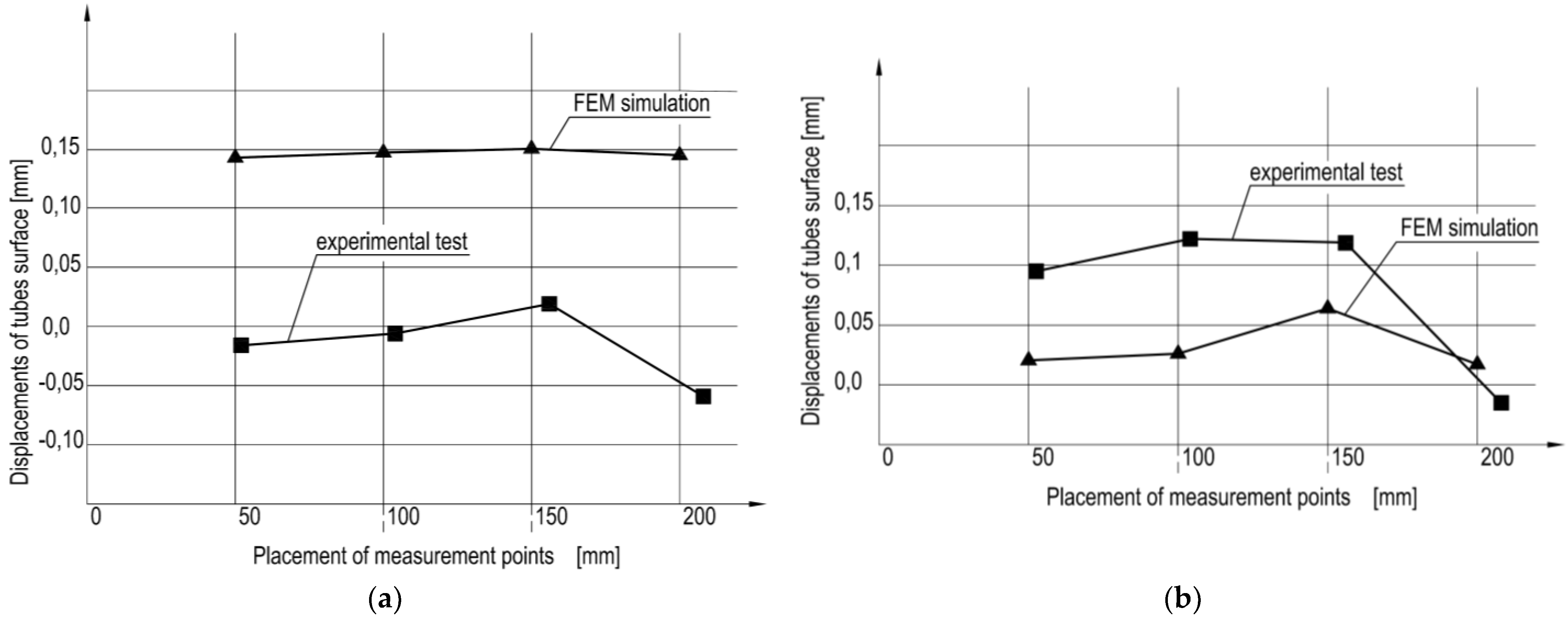
Figure 7 shows comparison of the global displacements obtained from computer FEM simulations and experimental tests on the test stand, for four points on the surfaces of the tubes of cylinders Ø = 30 mm and Ø = 50 mm. In the figure it can be seen that results of tests are consistent in terms of quality.
In both cases, the walls of the tubes move in the same direction, i.e., perpendicular to the cylinder axis, causing the tube diameter to increase (swelling). The displacement values can be considered similar. It is noticeable that experimental values for cylinder Ø = 30 mm are lower and for Ø = 50 mm higher than the simulation values. This is due to the mounting clearances and tendency of the support used on the test stand to yield.
4. Summary and Conclusions
The results of simulation strength tests carried out using the FEM show that:
- Stress values in the key elements of the cylinders made of plastic, which are loaded with pressure p = 6.3 MPa and force F = 4.45 kN (Ø = 30 mm) and F = 12.36 kN (Ø = 50 mm), are lower than the values of allowable stresses. The highest stress values occur in the cylinder tubes and reach values shown in equation (2) for the cylinder of internal diameter Ø = 30 mm and Equation (3) for cylinder of internal diameter Ø = 50 mm.σØ30 = 23.5 MPa < σallow = 30 MPaσØ50 = 20.5 MPa < σallow = 30 MPa
- Local deformations of the cylinder tube causing the increase in its diameter are shown in Equation (4) for cylinder of internal diameter Ø = 30 mm and Equation (5) for cylinder of internal diameter Ø = 50 mm.ΔdØ30 = 0.45 mmΔdØ50 = 0.50 mm
This increase is small enough to be compensated by the piston seals. Therefore, there is no danger of internal leakage in the cylinder connected to the swelling of the tube.
As a result of FEM studies, global deformations of the entire cylinder can be predicted. Global deformations are caused by a combination of the deflection of the cylinder structure and increase in the diameter of the tube.
Exploitation tests confirmed the nature of the predicted global deformations of the cylinder. The occurrence of the global and local deformations necessitates special design solutions. Examples of such solutions are a deformable connection between tube and cylinder caps and the fixation of the caps; however, other special design solutions are also possible. The use of special design solutions is intended to improve strength and stiffness of the structure as well as adjust the design material to a more elastic type, which is an unusual aspect in comparison to typical hydraulic cylinders made of metal.
Combined tests of cylinder deformations, consisting of computer simulations and an experiment, are an important step in the process of designing cylinders made of plastics. Such combined tests of a structure deformation of cylinders made of plastics complements the standard tests provided for typical metal cylinders. The extended tests of cylinders made of plastics allow, besides verification of operation correctness, for gathering information about behavior of their structures, which is different from typical metal cylinders. It is advantageous and even necessary in the case of new types of technical objects, which are cylinders made of plastics. Within the article, an example of prototype cylinders made of polyoxymethylene (POM) is introduced; however, other plastic materials may be used, e.g., polyphenylsulfide (PPS) or polyetheretherketone (PEEK). The use of different plastic materials may result in different behavior of the cylinder structure, so, in addition, the research method proposed in the article provides information on the behavior of plastics as design materials.
Research on different design solutions and behavior of structures made of different plastic materials using different research methods, e.g., electronic speckle pattern interferometry (ESPI), is one of the future directions of activity. Other potential future studies may concern using plastics for special solutions, e.g., water hydraulics.
Funding
This research received no external funding.
Acknowledgments
Calculations were carried out using resources provided by Wroclaw Centre for Networking and Supercomputing (http://wcss.pl), grant No. 391.
Conflicts of Interest
The author declares no conflict of interest.
References
- Li, Y. Review and Challenges of Lightweight Composite Hydraulic Cylinder. JMechE 2021, 57, 13–38. [Google Scholar] [CrossRef]
- Lubecki, M.; Stosiak, M.; Skačkauskas, P.; Karpenko, M.; Deptuła, A.; Urbanowicz, K. Development of Composite Hydraulic Actuators: A Review. Actuators 2022, 11, 365. [Google Scholar] [CrossRef]
- Solazzi, L. Design and experimental tests on hydraulic actuator made of composite material. Compos. Struct. 2019, 232, 111544. [Google Scholar] [CrossRef]
- Mantovani, S. Feasibility Analysis of a Double-Acting Composite Cylinder in High-Pressure Loading Conditions for Fluid Power Applications. Appl. Sci. 2020, 10, 826. [Google Scholar] [CrossRef] [Green Version]
- Błażejewski, W. Composite Pressure Vessels Reinforced with Fibers according to Mosaic Patterns; Oficyna Wydawnicza Politechniki Wrocławskiej: Wrocław, Poland, 2013. [Google Scholar]
- Stryczek, P. A Method of Designing Hydraulic Cylinders Made of Plastics; Raporty Wydziału Mechanicznego Politechniki Wrocławskiej: Wrocław, Poland, 2022; Ser. PRE; nr 20. 143 s. [Google Scholar]
- Kujawa, M.; Kowalewski, P.; Wieleba, W. The Influence of Deformation under Tension on Some Mechanical and Tribological Properties of High-Density Polyethylene. Polymers 2019, 11, 1429. [Google Scholar] [CrossRef] [Green Version]
- Rodionov, L.; Stryczek, J.; Rekadze, P.; Gafurov, S.; Prokofiev, A.; Shakhmatov, E. Challenges in design process of gear micropump from plastics. Arch. Civ. Mech. Eng. 2021, 21, 1–14. [Google Scholar] [CrossRef]
- Stryczek, J.; Antoniak, P.; Jakhno, O.; Kostyuk, D.; Kryuchkov, A.; Belov, G.; Rodionov, L. Visualisation research of the flow processes in the outlet chamber–outlet bridge–inlet chamber zone of the gear pumps. Arch. Civ. Mech. Eng. 2015, 15, 95–108. [Google Scholar] [CrossRef]
- Krawczyk, J.; Stryczek, J. Design and Experimental Research of a Plastic Gerotor Pump. In Proceedings of the Global Fluid Power Society PhD Symposium (GFPS), Samara, Russia, 18–20 July 2018. [Google Scholar]
- Banaś, M.; Antoniak, P.; Marciniak, L.; Stryczek, J. Visualization of flow phenomena in hydraulic throttle valves of plastics. In Proceedings of the 14th International Conference on Vibration Engineering and Technology of Machinery (VETOMAC XIV), Lisbon, Portugal, 10–13 September 2018. [Google Scholar]
- Stryczek, P.; Przystupa, F.W.; Banaś, M. Design and research on a hydraulic cylinder with plastic components. In Proceedings of the ASME 2016 9th FPNI Ph.D. Symposium on Fluid Power, Florianópolis, SC, Brazil, 26–28 October 2016. [Google Scholar]
- Zienkiewicz, O.C. Finite Element Metod; Arkady: Warszawa, Poland, 1972. [Google Scholar]
- Rusiński, E.; Czmochowski, J.; Smolnicki, T. Advanced Finite Element Method in the Load-Bearing Structures; Oficyna Wydawnicza Politechniki Wrocławskiej: Wrocław, Poland, 2000. [Google Scholar]
- Banaś, M. Internal Leakages in a Water Hydraulic Pump with Gears From Plastic. Int. J. Fluid Power 2021, 21, 347–362. [Google Scholar] [CrossRef]
- Kim, A.; Dudkin, M.; Valiov, A.; Gurianov, G. New vibroscreen with additional feed elements. Arch. Civ. Mech. Eng. 2017, 17, 786–794. [Google Scholar] [CrossRef]
- Milojević, S.; Savić, S.; Marić, D.; Stopka, O.; Krstić, B.; Stojanović, B. Correlation between Emission and Combustion Characteristics with the Compression Ratio and Fuel Injection Timing in Tribologically Optimized Diesel Engine. Tehnicki Vjesnik 2022, 29, 1210–1219. [Google Scholar] [CrossRef]
- Goljat, S.; Tič, V.; Lovrec, D. Prevention of Water Ingress in Hydraulic Systems. Appl. Eng. Lett. J. Eng. Appl. Sci. 2021, 6, 99–104. [Google Scholar] [CrossRef]
Figure 1.
Computer models of plastic cylinder of internal diameter Ø30 mm and stroke S = 200 mm: (a) geometric model, (b) discrete model, (c) model of restraints, (d) model of loads.
Figure 1.
Computer models of plastic cylinder of internal diameter Ø30 mm and stroke S = 200 mm: (a) geometric model, (b) discrete model, (c) model of restraints, (d) model of loads.

Figure 2.
Maps of stress (strain) of plastic cylinder of internal diameter Ø30 mm and stroke S = 200 mm under load of nominal pressure p = 6.3 MPa and force F = 4.5 kN: 1—tube, 2—piston with piston rod, 3—bottom cap, 4—gland cap, 5—tie rods; (a) extension S = 0; (b) extension S = 0.5; (c) extension S = 1, (d) retraction S = 0.
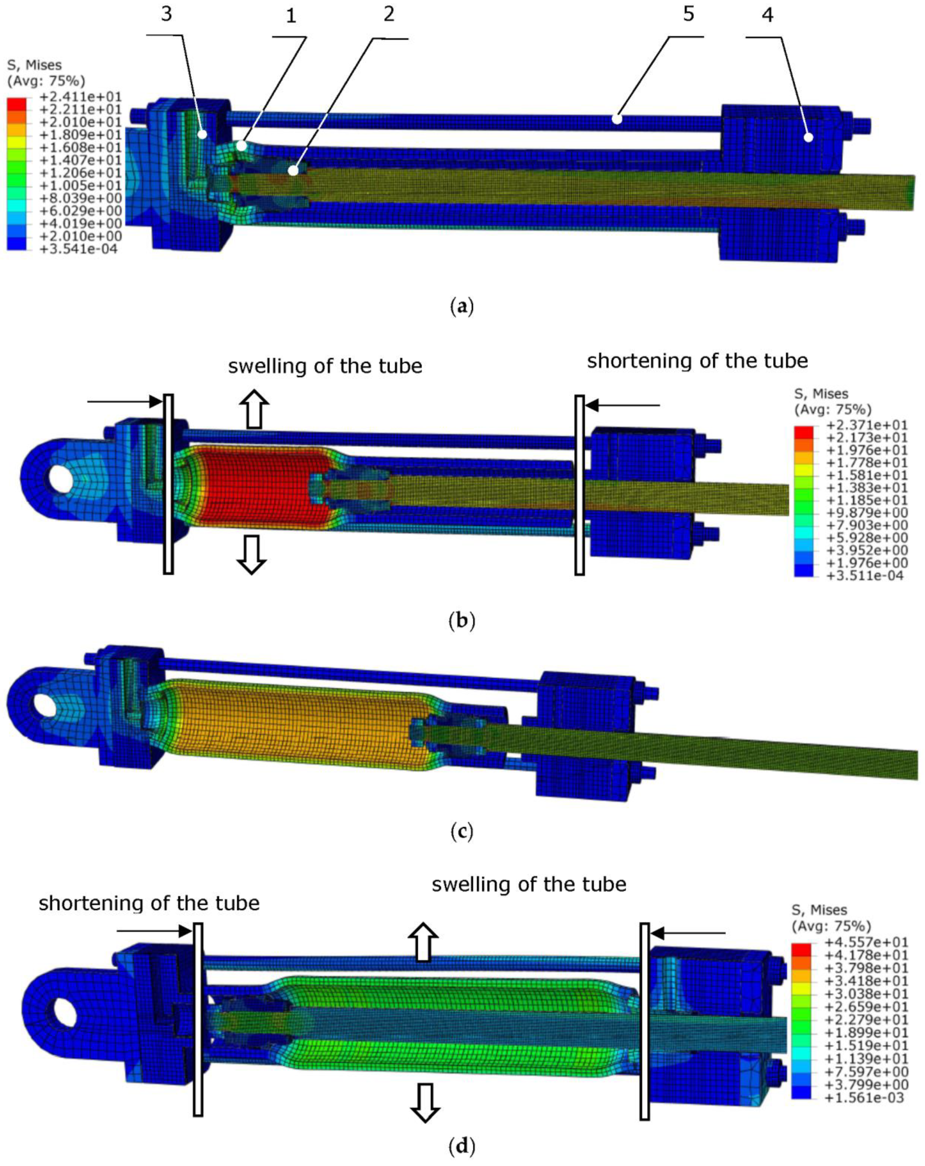
Figure 3.
Global deformation of plastic cylinders obtained by FEM: (a) cylinder of internal diameter Ø30 mm; (b) cylinder of internal diameter Ø50 mm.
Figure 3.
Global deformation of plastic cylinders obtained by FEM: (a) cylinder of internal diameter Ø30 mm; (b) cylinder of internal diameter Ø50 mm.
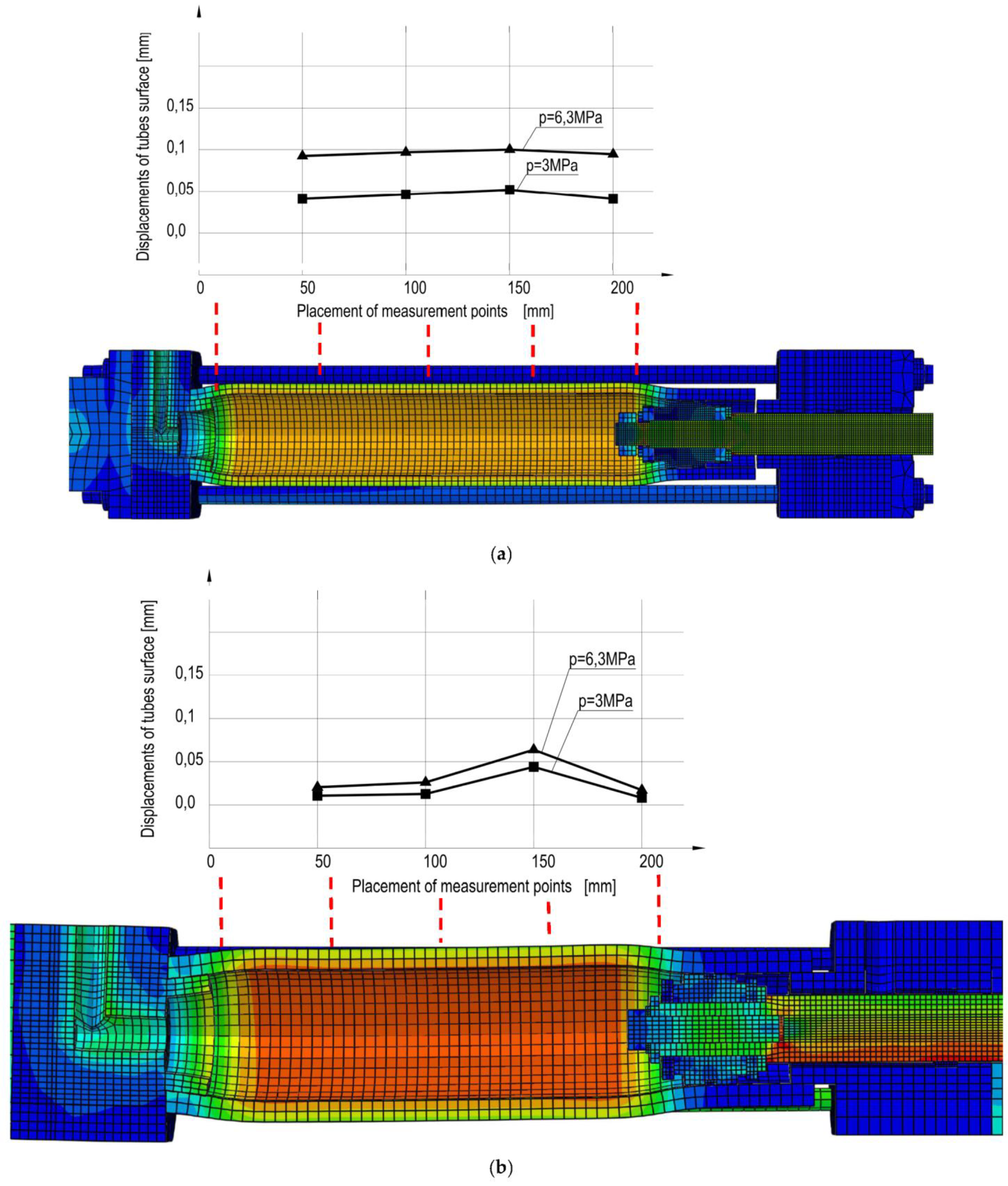
Figure 4.
Scheme of formation of global deformations of a plastic cylinder structure: (a) extension phase; (b) retraction phase.
Figure 4.
Scheme of formation of global deformations of a plastic cylinder structure: (a) extension phase; (b) retraction phase.

Figure 5.
Testing stand for hydraulic cylinder made of plastics: (a) cylinder model Ø30 S = 200 mm mounted on the stand; (b) displacement sensors mounted in special adapter.
Figure 5.
Testing stand for hydraulic cylinder made of plastics: (a) cylinder model Ø30 S = 200 mm mounted on the stand; (b) displacement sensors mounted in special adapter.
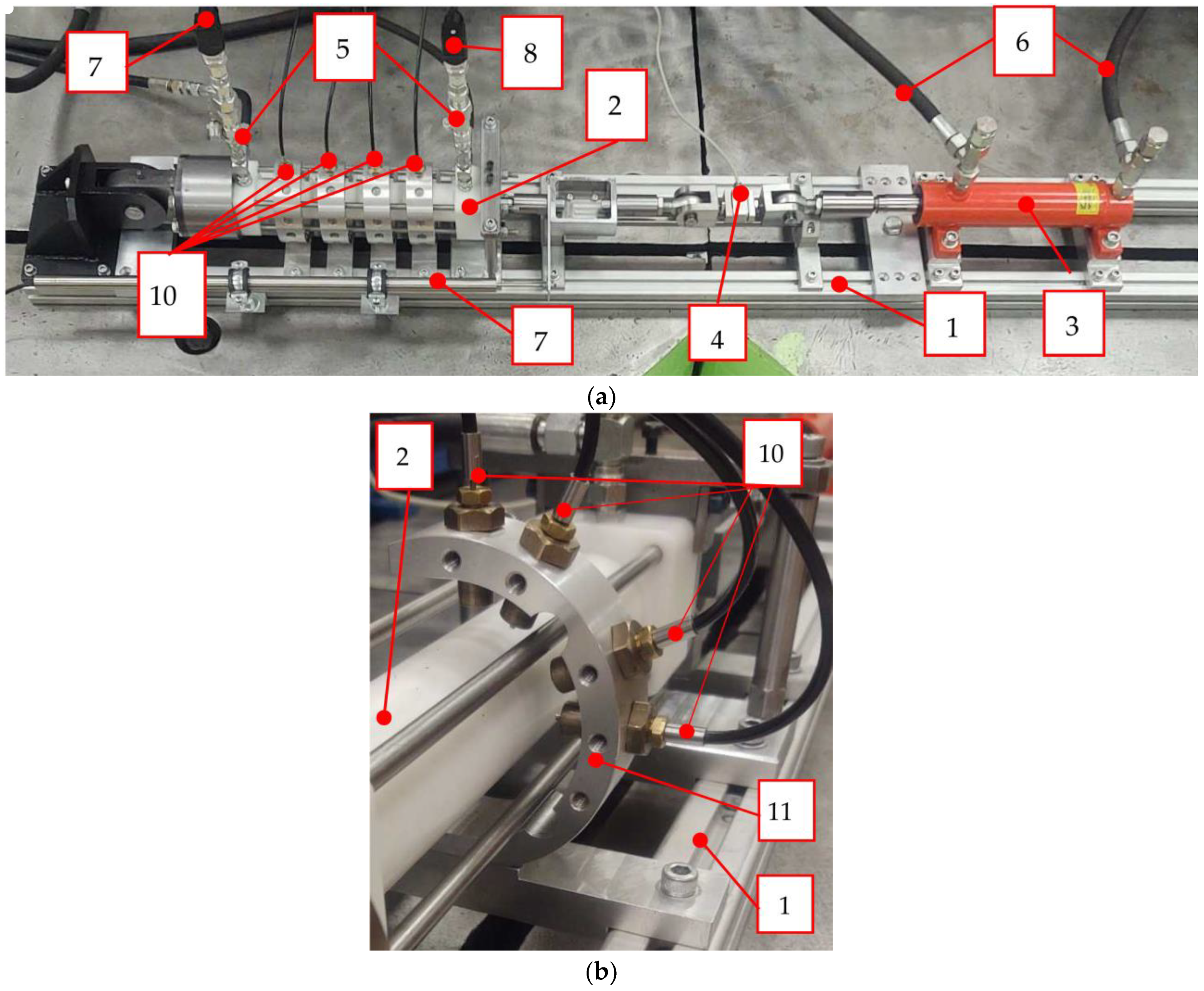
Figure 6.
Global deformation of plastic cylinder models obtained by experimental test: (a) cylinder of internal diameter Ø30 mm; (b) cylinder of internal diameter Ø50 mm.
Figure 6.
Global deformation of plastic cylinder models obtained by experimental test: (a) cylinder of internal diameter Ø30 mm; (b) cylinder of internal diameter Ø50 mm.
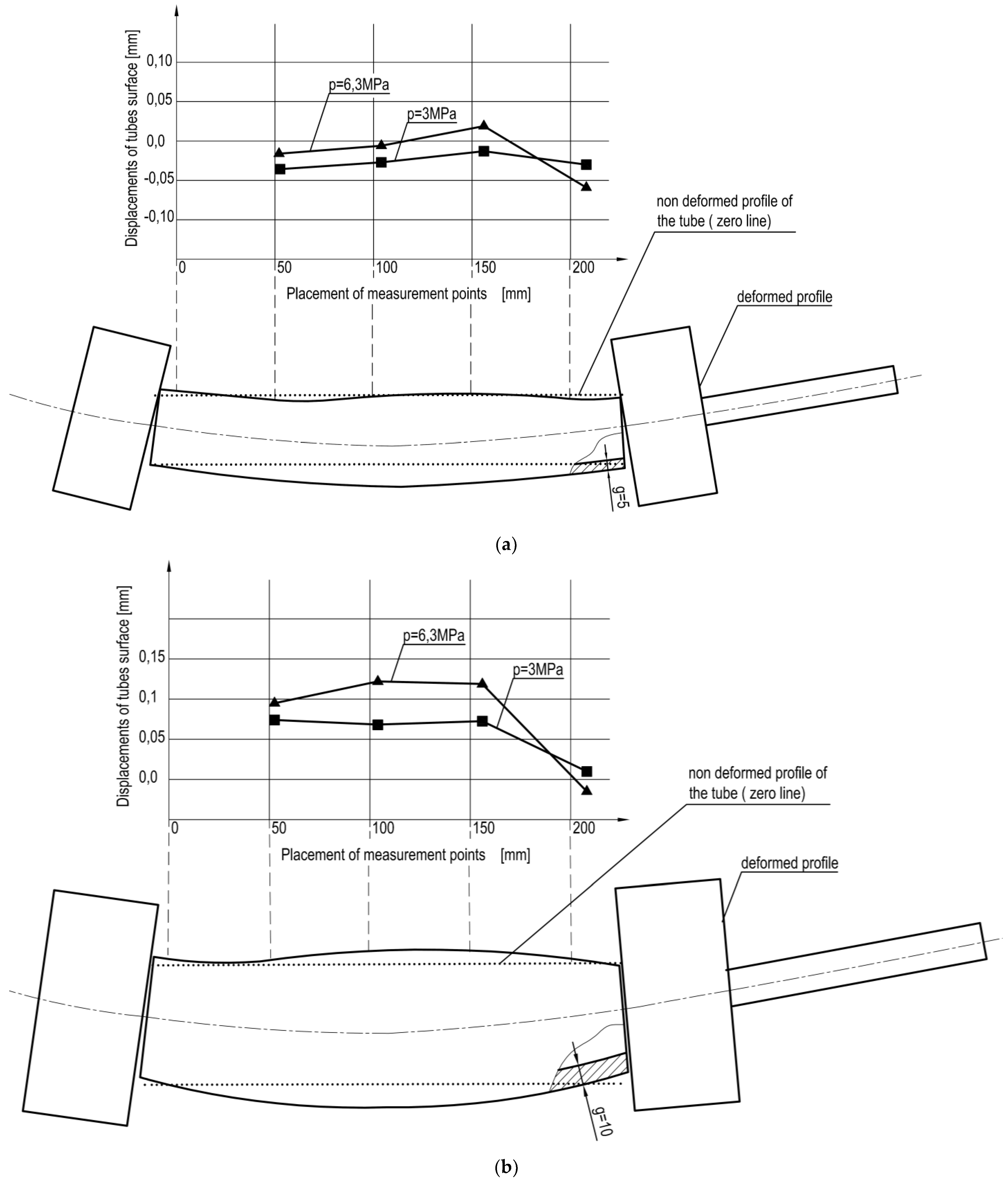
Figure 7.
Comparison of the global displacements obtained from computer FEM simulations and experimental tests on the test stand: (a) cylinder of internal diameter Ø30 mm; (b) cylinder of internal diameter Ø50 mm.
Figure 7.
Comparison of the global displacements obtained from computer FEM simulations and experimental tests on the test stand: (a) cylinder of internal diameter Ø30 mm; (b) cylinder of internal diameter Ø50 mm.

Table 1.
Values of maximum stresses σmax and strains Δmax obtained during simulations for individual elements of the cylinders.
Table 1.
Values of maximum stresses σmax and strains Δmax obtained during simulations for individual elements of the cylinders.
| No. | Part | Load (MPa), (kN) | Maximum Stress (MPa) | Allowable Stress (MPa) | Maximum Strain (mm) |
|---|---|---|---|---|---|
| cylinder Ø30 mm, S = 200 mm | |||||
| 1 | Tube | 6.3 (MPa) 4.45 (kN) | 23.5 | 30 | 0.45 |
| 2 | Piston | 28.4 | 0.48 | ||
| 3 | Bottom cap | 15.7 | 0.09 | ||
| 4 | Gland cap | 16.4 | 0.1 | ||
| 5 | Tie rods | 20.2 | 0.04 | ||
| cylinder Ø50 mm, S = 200 mm | |||||
| 1 | Tube | 6.3 (MPa) 12.36 (kN) | 20.5 | 30 | 0.50 |
| 2 | Piston | 27.9 | 0.52 | ||
| 3 | Bottom cap | 17.5 | 0.27 | ||
| 4 | Gland cap | 20.,3 | 0.2 | ||
| 5 | Tie rods | 15.6 | 0.9 | ||
Disclaimer/Publisher’s Note: The statements, opinions and data contained in all publications are solely those of the individual author(s) and contributor(s) and not of MDPI and/or the editor(s). MDPI and/or the editor(s) disclaim responsibility for any injury to people or property resulting from any ideas, methods, instructions or products referred to in the content. |
© 2023 by the author. Licensee MDPI, Basel, Switzerland. This article is an open access article distributed under the terms and conditions of the Creative Commons Attribution (CC BY) license (https://creativecommons.org/licenses/by/4.0/).
Share and Cite
MDPI and ACS Style
Stryczek, P. Research on Deformation of Hydraulic Cylinders Made of Plastics. Energies 2023, 16, 5708. https://doi.org/10.3390/en16155708
AMA Style
Stryczek P. Research on Deformation of Hydraulic Cylinders Made of Plastics. Energies. 2023; 16(15):5708. https://doi.org/10.3390/en16155708
Chicago/Turabian StyleStryczek, Piotr. 2023. "Research on Deformation of Hydraulic Cylinders Made of Plastics" Energies 16, no. 15: 5708. https://doi.org/10.3390/en16155708
Note that from the first issue of 2016, this journal uses article numbers instead of page numbers. See further details here.