
Techniques of Fluidic Thrust Vectoring in Jet Engine Nozzles: A Review

 , ,
, , 
Abstract
:1. Introduction
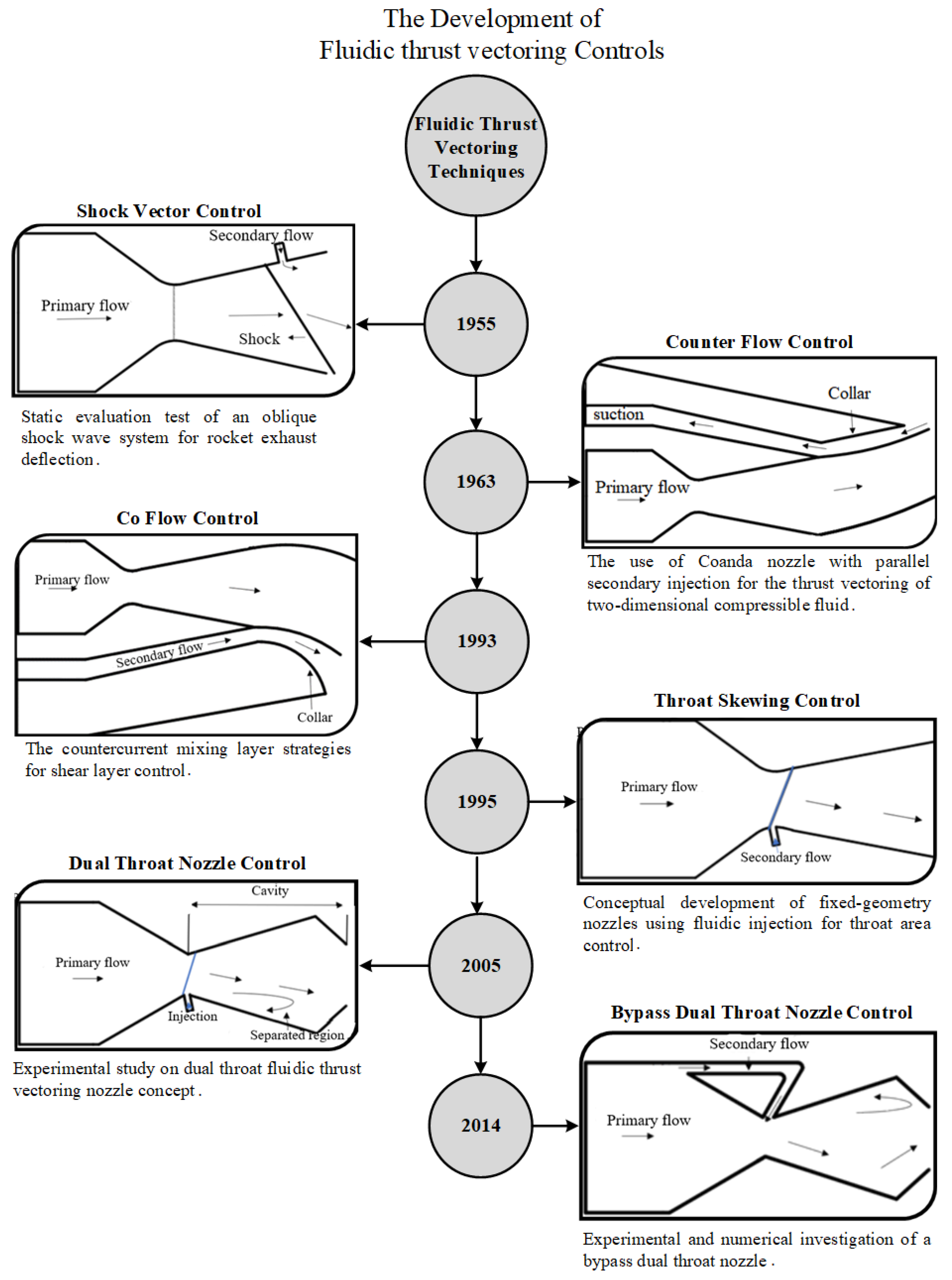
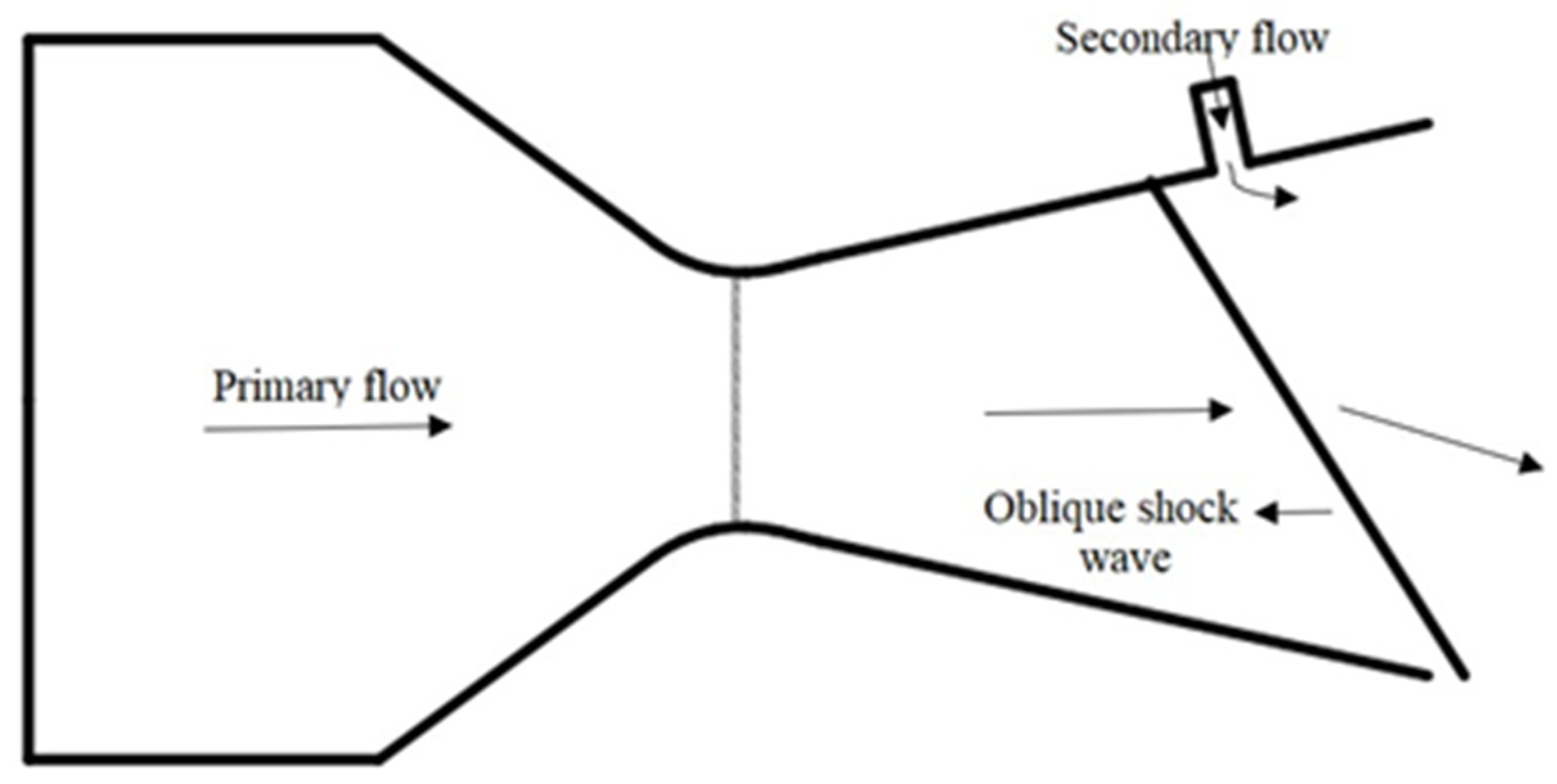
2. Shock Vector Control (SVC)
2.1. Effect of NPR and SPR
2.2. Transverse Injection
2.3. Slot Injection
2.4. Injection Configurations
2.5. Effect of Hot and Cold States
2.6. Bypass Flow Injection
2.7. Injectors
3. Counter Flow Control (CFC)
3.1. Shear Layer CFTV
3.2. Collar Geometry
3.3. Effect of NPR
4. Co-Flow Control (Co-Flow TVC)
4.1. Three Significant Zones
4.2. Swept and Non-Swept Nozzle
5. Throat Skewing Control (TSC)
5.1. Single and Multi-Axis Nozzle
5.2. Pitch and Yaw Thrust Vectoring
5.3. Slot Configuration

| Parameters | Effects | Ref |
|---|---|---|
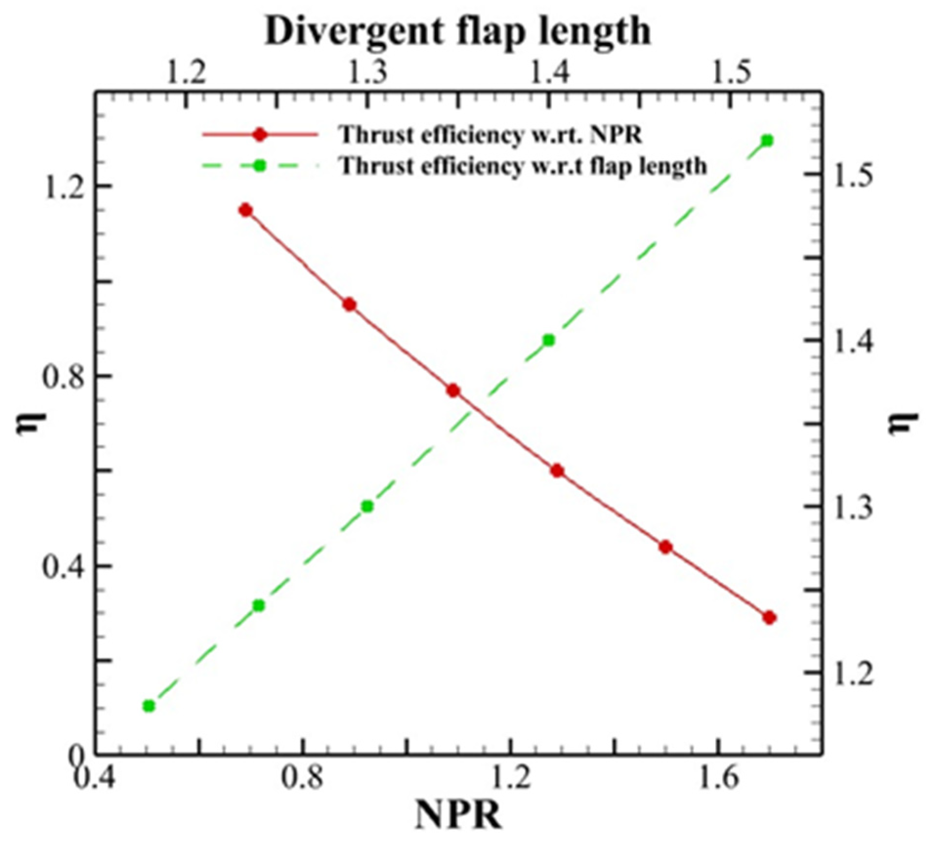
| Divergent flap length | Flap length affected the vectoring effectiveness. For a long flap length, oblique shock occurred in the divergent portion of the nozzle, thus reducing vectoring effectiveness. Similarly, for a very short flap, the secondary flow detached from the flap, which resulted in poor vectoring effectiveness | [96] |
| Expansion area ratio | Increasing the expansion ratio provided an increased pitch vectoring angle. It also moderately affected the vectoring effectiveness | [93] |
| Injector angle | Injector angle strongly and inversely affected the vectoring effectiveness. For a smaller injector angle, the vectoring effectiveness increased | [100] |
| NPR | NPR had a small effect on the vectoring effectiveness. TS was suggested to be robust to variation in flight condition | [95] |
| Year | Title | Model | Varying Parameters | Computational Setup and Details | Conclusions | Ref |
|---|---|---|---|---|---|---|
| 2001 | Demonstration of Fluidic Throat Skewing for Thrust Vectoring in Structurally Fixed Nozzles | 3D conformal nozzle | NPR = 2.0–5.5 | Design of experiments for single and multi-axis TV concept. Cold-flow test. | TV performance increases with an increase in the secondary mass flow. Both pitch and yaw TV data trends were observed. | [95] |
| 2002 | Fluidic Thrust Vectoring and Throat Control Exhaust Nozzle | 3D FAVE nozzle | Mass flow Ratio = 0–0.3 | NPARC code /Spalart Allmaras Model | NPR impact was reduced on the TV angle due to the secondary flow at the nozzle throat. | [98] |
| 2012 | Combination of Fluidic Thrust Modulation and Vectoring in a 2D Nozzle | 2D nozzle | Area ratio = 0.1–0.2 Injection angle = 30°–90° NPR = 30–40 | Fluent/k-ω Model | Area ratio, injection angle, and NPR had a significant effect on thrust modulation. | [100] |
| 2017 | Thrust Control by Fluidic Injection in Solid Rocket Motors | Combination of TS and SVC nozzle | Mass flow Ratio = 0–0.6 | Cold thermal flow test | The combination can achieve better TV performance for solid rocket motors. | [101] |
| 2019 | Secondary Flow TVC for Fluidic-Throat Nozzles | 6 types of axisymmetric nozzle | Injector location = 0.12–0.5 | Cold test flow | Better TV performance can be achieved for different injection schemes. | [102] |
| 2020 | Experimental research on vector control features of a pulse detonation tube with fluidic nozzle | 3D nozzle | Injection location = 30–60 mm, 10 injection combinations | Valveless operation mode | For adjusting the direction of exhaust gases, asymmetric injections were found to be effective. Additionally, the combination of throat and divergent secondary flow injection obtained efficient TVC. | [103] |
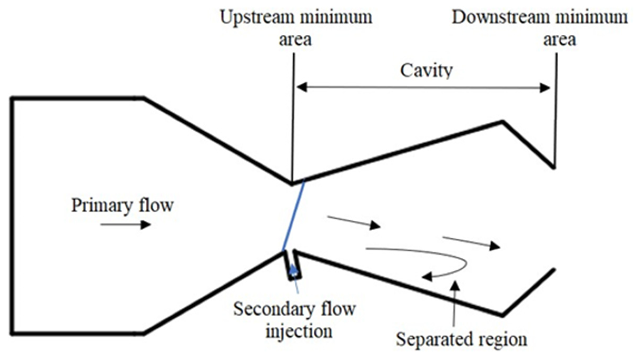
6. Dual Throat Nozzle (DTN)
6.1. Effect of NPR and SPR
6.2. Unsteady Simulation
6.3. DTN-Starting Problem
6.4. Fixed and Variable Geometry
6.5. Secondary Injection
| Year | Title | Model | Varying Parameters | Computational Setup and Details | Conclusions | Ref |
|---|---|---|---|---|---|---|
| 2009 | Preliminary Analysis and Design Enhancements of a Dual Throat FTV Nozzle Concept | 2D nozzle | NPR = 2–10 | Fluent/k-ε Model | For the designed geometry the MFR and TV angle was found to be 5.47 kg/s and 24.5°. | [122] |
| 2013 | Effects of Cavity on the Performance of Dual Throat Nozzle During the Thrust-Vectoring Starting Transient Process | 2D nozzle with 3 cases | NPR = 1–4 | Fluent/k-ε Model 21,600 nodes, = 101,325 Pa = 300 k | Negative TV angle appeared before the nozzle produced an efficient TV angle. | [111] |
| 2015 | Numerical Simulation of Fluidic Thrust vectoring | 2D nozzle | NPR = 2–10 | Fluent/Spalart- Allmaras Model | Increasing the secondary MFR resulted in increased TV angles. | [123] |
| 2016 | Experimental and Computational Investigation of a Dual-Throat Fluidic Thrust-Vectoring Nozzle | 2D nozzle with 3 different secondary injection geometries | NPR = 1–4 Air and nitrogen | Fluent/k-ε Model 560,000 grid cells, = 101,325 Pa = 300 k | NPR of 2 had the most impact on TV angle. Whereas the influence of secondary injection was reduced at NPR of 4. | [120] |
| 2016 | Study of Starting Problem of Axisymmetric Divergent Dual Throat Nozzle | 2D nozzle | Expansion ratio = 1.1025–1.96 Radius ratio = 1.05–1.4 | Fluent/k-ε Model 21,600 nodes, = 101,325 Pa = 300 k | Higher expansion ratios created shock oscillations in the cavity. | [112] |
| 2019 | Performance Analyses of Fluidic Thrust Vector Control System Using Dual Throat Nozzle | 2D nozzle | Nozzle A with identical first and second throat and Nozzle B with second throat of 1.5 times the first throat | Direct simulation Monte Carlo method | Nozzle achieved 19° of TV angle, however, a TV angle of 15° was achieved for another configuration of nozzle. | [124] |
| 2020 | Numerical Study of Fluidic Thrust Vector Control Using Dual Throat Nozzle | 3D rectangular nozzle | NPR = 2–5 X/L = 0.25–0.67 J = 0.43–2.76 | Fluent/k-ω Model 2,078,000 grid cells, = 101,325 Pa = 300 k | To obtain best TV performance the optimal choice for NPR is 4. | [105] |
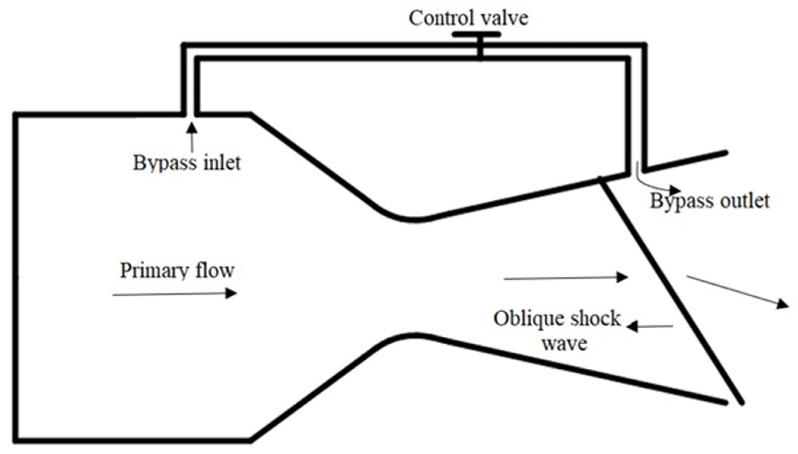
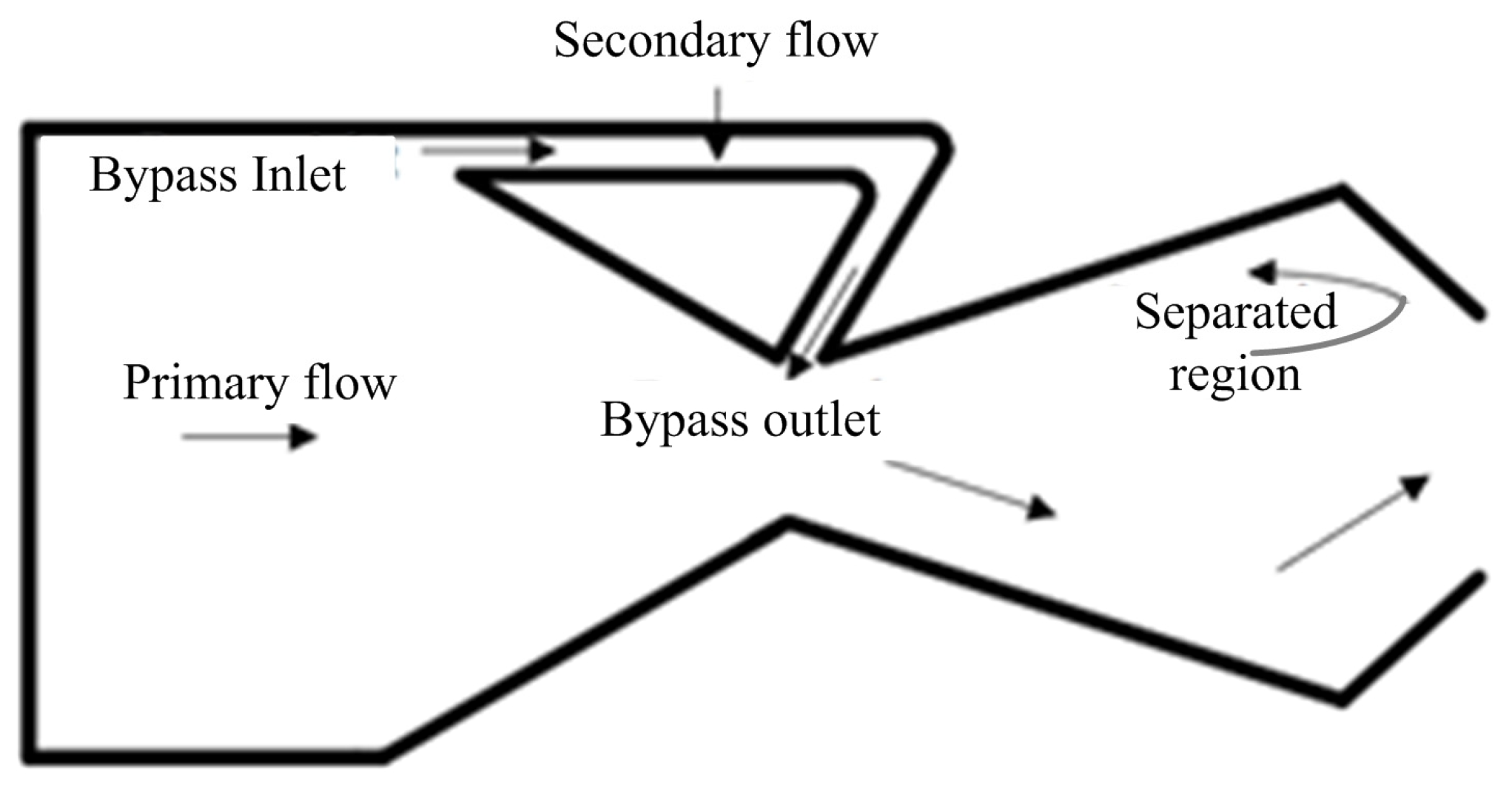
7. Bypass Dual Throat Nozzle (BDTN)
7.1. Effect of NPR
7.2. Secondary Mass Flow Modulation
7.3. Axisymmetric Divergent BDTN
7.4. Comparison of DTN and BDTN
8. Comparison of FTVCs
8.1. Design
8.2. Impact on System
8.3. Implementation
8.4. Thrust Vectoring Angle
8.5. Thrust Coefficient
8.6. Thrust Efficiency
8.7. Thrust Losses
8.8. Negative Consequences
8.9. Potential Problems
9. Conclusions
Author Contributions
Funding
Data Availability Statement
Conflicts of Interest
Nomenclature
| λ | Injection angle |
| FTV | Fluidic thrust vectoring |
| P0 | Stagnation pressure |
| FTVC | Fluidic thrust vectoring control |
| Pa | Ambient pressure |
| J | Momentum flux ratio |
| Ppri | Primary flow pressure |
| MFR | Mass flow rate |
| Psec | Secondary flow pressure |
| MTV | Mechanical thrust vectoring |
| T0 | Stagnation temperature |
| NPR | Nozzle pressure ratio |
| Ta | Ambient temperature |
| SPR | Secondary pressure ratio |
| BDTN | Bypass dual throat nozzle |
| STR | System thrust ratio |
| BFR | Bypass flow rate |
| SVC | Shock vector control |
| CD | Convergent-Divergent |
| TS | Throat skewing |
| CDC | Convergent-Divergent-Convergent |
| TV | Thrust vectoring |
| CFTV | Counter flow thrust vectoring |
| TVC | Thrust vector control injection |
| DTN | Dual throat nozzle |
| X/L | location |
| FAVE | Fixed aperture vectoring exhaust |
References
- Ikaza, D. Thrust vectoring nozzle for modern military aircraft. In Proceedings of the 22nd Congress of International Council of the Aeronautical Sciences, Harrogate, UK, 27 August–1 September 2000. [Google Scholar]
- Francis, M.S. Air Vehicle Management with Integrated Thrust-Vector Control. AIAA J. 2018, 56, 4741–4751. [Google Scholar] [CrossRef]
- Henderson, B. Fifty years of fluidic injection for jet noise reduction. Int. J. Aeroacoustics 2010, 9, 91–122. [Google Scholar] [CrossRef]
- Hanumanthrao, K.; Ragothaman, S.; Kumar, B.A.; Prasad, M.G.; Kumar, V.S. Studies on fluidic injection thrust vectoring in aerospike nozzles. In Proceedings of the 49th AIAA Aerospace Sciences Meeting Including the New Horizons Forum and Aerospace Exposition, Orlando, FL, USA, 4–7 January 2011; p. 293. [Google Scholar]
- Wing, D.J. Static Investigation of Two Fluidic Thrust-Vectoring Concepts on a Two-Dimensional Convergent-Divergent Nozzle; National Aeronautics and Space Administration, Langley Research Center: Hampton, VA, USA, 1994; Volume 4574.
- Wing, D.J.; Giuliano, V.J. Fluidic thrust vectoring of an axisymmetric exhaust nozzle at static conditions. In Proceedings of the ASME Fluids Engineering Division Summer Meeting, Vancouver, BC, Canada, 22–26 June 1997; pp. 22–26. [Google Scholar]
- Broadwell, J.E. Analysis of the fluid mechanics of secondary injection for thrust vector control. AIAA J. 1963, 1, 1067–1075. [Google Scholar] [CrossRef]
- Rifky, S. Return flight. Art Am. 2015, 103, 55–58. [Google Scholar]
- Cuppoletti, D.R.; Gutmark, E.J.; Hafsteinsson, H.E.; Eriksson, L.E.; Prisell, E. Analysis of Supersonic Jet Thrust with Fluidic Injection. In Proceedings of the 52nd Aerospace Sciences Meeting, National Harbor, MD, USA, 13–17 January 2014; p. 0523. [Google Scholar]
- Gamble, E.; DeFrancesco, R.; Haid, D.; Buckwalter, D. Fluidic nozzle to improve transonic pitch and thrust performance of hypersonic vehicle. In Proceedings of the 41st AIAA/ASME/SAE/ASEE Joint Propulsion Conference & Exhibit, Tucson, AZ, USA, 10–13 July 2005; p. 3501. [Google Scholar]
- Kral, L.D. Active Flow Control Technology; ASME Fluids Engineering Technical Brief; Washington University in St. Louis: St. Louis, MO, USA, 1999. [Google Scholar]
- Deere, K. Pab3d simulations of a nozzle with fluidic injection for yaw thrust-vector control. In Proceedings of the 34th AIAA/ASME/SAE/ASEE Joint Propulsion Conference and Exhibit, Cleveland, OH, USA, 13–15 July 1998; p. 3254. [Google Scholar]
- Anderson, C.; Giuliano, V.; Wing, D. Investigation of hybrid fluidic/mechanical thrust vectoring for fixed-exit exhaust nozzles. In Proceedings of the 33rd Joint Propulsion Conference and Exhibit, Seattle, WA, USA, 6–9 July 1997; p. 3148. [Google Scholar]
- Giuliano, V.; Wing, D. Static investigation of a fixed-aperture nozzle employing fluidic injection for multiaxis thrust vector control. In Proceedings of the 33rd Joint Propulsion Conference and Exhibit, Seattle, WA, USA, 6–9 July 1997; p. 3149. [Google Scholar]
- Schulmeister, M. Static Evaluation Tests of an Oblique Shock Wave System for Rocket Exhaust Deflection; NARTS 77; US Naval Air Rocket Test Station: Dover, NJ, USA, 1955. [Google Scholar]
- Panzarella, P. The Use of a Coanda Nozzle with Parallel Secondary Injection for the Thrust Vectoring of a Two-Dimensional Compressible Fluid. Ph.D. Thesis, Air Force Institute of Technology, Dayton, OH, USA, 1965. [Google Scholar]
- Strykowski, P.; Krothapalli, A. The countercurrent mixing layer-strategies for shear-layer control. In Proceedings of the 3rd Shear Flow Conference, Orlando, FL, USA, 6–9 July 1993; p. 3260. [Google Scholar]
- Miller, D.; Catt, J. Conceptual development of fixed-geometry nozzles using fluidic injection for throat area control. In Proceedings of the 31st Joint Propulsion Conference and Exhibit, San Diego, CA, USA, 10–12 July 1995; p. 2603. [Google Scholar]
- Flamm, J.; Deere, K.; Berrier, B.; Johnson, S.; Mason, M. Experimental study of a dual-throat fluidic thrust-vectoring nozzle concept. In Proceedings of the 41st AIAA/ASME/SAE/ASEE Joint Propulsion Conference & Exhibit, Tucson, AZ, USA, 10–13 July 2005; p. 3503. [Google Scholar]
- Gu, R.; Xu, J.; Guo, S. Experimental and Numerical Investigations of a Bypass Dual Throat Nozzle. J. Eng. Gas Turbines Power 2014, 136, 084501. [Google Scholar] [CrossRef]
- Hamed, A.; Laskowski, G.; Hamed, A.; Laskowski, G. A parametric study of slot injection thrust vectoring in a 2dcd nozzle. In Proceedings of the 33rd Joint Propulsion Conference and Exhibit, Seattle, WA, USA, 6–9 July 1997; p. 3154. [Google Scholar]
- Deere, K. Computational investigation of the aerodynamic effects on fluidic thrust vectoring. In Proceedings of the 36th AIAA/ASME/SAE/ASEE Joint Propulsion Conference and Exhibit, Las Vegas, NV, USA, 24–28 July 2000; p. 3598. [Google Scholar]
- Neely, A.; Gesto, F.; Young, J. Performance studies of shock vector control fluidic thrust vectoring. In Proceedings of the 43rd AIAA/ASME/SAE/ASEE Joint Propulsion Conference & Exhibit, Cincinnati, OH, USA, 8–11 July 2007; p. 5086. [Google Scholar]
- Ferlauto, M.; Marsilio, R. Computational investigation of injection effects on shock vector control performance. In Proceedings of the 2018 Joint Propulsion Conference, Cincinnati, OH, USA, 9–11 July 2018; p. 4934. [Google Scholar]
- Wu, K.; Kim, H.D. Numerical study on the shock vector control in a rectangular supersonic nozzle. Proc. Inst. Mech. Eng. Part G J. Aerosp. Eng. 2019, 233, 4943–4965. [Google Scholar] [CrossRef]
- Forghany, F.; Taeibe-Rahni, M.; Asadollahi-Ghohieh, A.; Banazdeh, A. Numerical investigation of injection angle effects on shock vector control performance. Proc. Inst. Mech. Eng. Part G J. Aerosp. Eng. 2019, 233, 405–417. [Google Scholar] [CrossRef]
- Li, L.; Saito, T. Numerical and experimental investigations of fluidic thrust vectoring mechanism. Int. J. Aerosp. Innov. 2012, 4, 53–64. [Google Scholar] [CrossRef]
- Li, L.; Saito, T. A survey of performance of fluidic thrust vectoring mechanisms by numerical and experimental studies. Int. J. Aerosp. Innov. 2013, 5, 51–60. [Google Scholar] [CrossRef]
- Li, L.; Hirota, M.; Ouchi, K.; Saito, T. Evaluation of fluidic thrust vectoring nozzle via thrust pitching angle and thrust pitching moment. Shock. Waves 2016, 27, 53–61. [Google Scholar] [CrossRef]
- Zmijanovic, Z.; Lago, V.; Palerm, S.; Oswald, J.; Sellam, M.; Chpoun, A. Thrust shock vector control of an axisymmetric cd nozzle via transverse gas injection. In Proceedings of the 28th International Symposium on Shock Waves, Manchester, UK, 17–22 July 2011; Springer: Berlin/Heidelberg, Germany, 2012; pp. 171–177. [Google Scholar]
- Saito, T.; Fujimoto, T. Numerical studies of shock vector control for deflecting nozzle exhaust flows. In Shock Waves; Springer: Berlin/Heidelberg, Germany, 2009; pp. 985–990. [Google Scholar]
- Deng, R.; Kong, F.; Kim, H.D. Numerical simulation of fluidic thrust vectoring in an axisymmetric supersonic nozzle. J. Mech. Sci. Technol. 2014, 28, 4979–4987. [Google Scholar] [CrossRef]
- Spaid, F.W.; Zukoski, E.E. A study of the interaction of gaseous jets from transverse slots with supersonic external flows. AIAA J. 1968, 6, 205–212. [Google Scholar] [CrossRef]
- Schetz, J.A.; Billig, F.S. Penetration of gaseous jets injected into a supersonic stream. J. Spacecr. Rocket. 1966, 3, 1658–1665. [Google Scholar] [CrossRef]
- Shi, J. Performance estimation for fluidic thrust vectoring nozzle coupled with aero-engine. In Proceedings of the 50th AIAA/ASME/SAE/ASEE Joint Propulsion Conference, Cleveland, OH, USA, 28–30 July 2014; p. 3771. [Google Scholar]
- Sekar, T.C.; Kushari, A.; Mody, B.; Uthup, B. Fluidic thrust vectoring using transverse jet injection in a converging nozzle with aft-deck. Exp. Therm. Fluid Sci. 2017, 86, 189–203. [Google Scholar] [CrossRef]
- Chenault, C.F.; Beran, P.S. Ke and Reynolds Stress Turbulence Model Comparisons for Two-Dimensional Injection Flows. AIAA J. 1998, 36, 1401–1412. [Google Scholar] [CrossRef]
- Sellam, M.; Chpoun, A.; Zmijanovic, V.; Lago, V. Fluidic thrust vectoring of an axisymmetrical nozzle: An analytical model. Int. J. Aerodyn. 2012, 2, 193. [Google Scholar] [CrossRef]
- Wu, K.; Kim, T.H.; Kim, H.D. Theoretical and Numerical Analyses of Aerodynamic Characteristics on Shock Vector Control. J. Aerosp. Eng. 2020, 33, 04020050. [Google Scholar] [CrossRef]
- Zmijanovic, V.; Leger, L.; Depussay, E.; Sellam, M.; Chpoun, A. Experimental–Numerical Parametric Investigation of a Rocket Nozzle Secondary Injection Thrust Vectoring. J. Propuls. Power 2016, 32, 196–213. [Google Scholar] [CrossRef]
- Delery, J.M. Shock wave/turbulent boundary layer interaction and its control. Prog. Aerosp. Sci. 1985, 22, 209–280. [Google Scholar] [CrossRef]
- Korkegi, R.H. Effect of Transition on Three-Dimensional Shock- Wave/Boundary-Layer Interaction. AIAA J. 1972, 10, 361–363. [Google Scholar] [CrossRef]
- Raghunathan, S. Passive control of shock-boundary layer interaction. Prog. Aerosp. Sci. 1988, 25, 271–296. [Google Scholar] [CrossRef]
- Green, J. Interactions between shock waves and turbulent boundary layers. Prog. Aerosp. Sci. 1970, 11, 235–340. [Google Scholar] [CrossRef]
- John, B.; Kulkarni, V.N.; Natarajan, G. Shock wave boundary layer interactions in hypersonic flows. Int. J. Heat Mass Transf. 2014, 70, 81–90. [Google Scholar] [CrossRef]
- Alzner, E.; Zakkay, V. Turbulent Boundary-Layer Shock Interaction with and without Injection. AIAA J. 1971, 9, 1769–1776. [Google Scholar] [CrossRef]
- Spaid, F.W. Two-dimensional jet interaction studies at large values of Reynolds and Mach numbers. AIAA J. 1975, 13, 1430–1434. [Google Scholar] [CrossRef]
- Jingwei, S.; Li, Z.; Zhanxue, W.; Xiaolin, S. Investigation on Flowfield Characteristics and Performance of Shock Vector Control Nozzle Based on Confined Transverse Injection. J. Eng. Gas Turbines Power 2016, 138, 101502. [Google Scholar] [CrossRef]
- Waithe, K.; Deere, K. An experimental and computational investigation of multiple injection ports in a convergent-divergent nozzle for fluidic thrust vectoring. In Proceedings of the 21st AIAA Applied Aerodynamics Conference, Orlando, FL, USA, 23–26 June 2003; p. 3802. [Google Scholar]
- Mnafeg, I.; Abichou, A.; Beji, L. Thrust vectoring control of supersonic flow through an orifice injector. Int. J. Mech. Aerosp. Ind. Mechatron. Manuf. Eng. 2015, 9, 1352–1358. [Google Scholar]
- Blake, B.A. Numerical investigation of fluidic injection as a means of thrust control. UNSW Canberra ADFA J. Undergrad. Eng. Res. 2009, 2, 1–10. [Google Scholar]
- Zhang, Q.; Wang, K.; Dong, R.; Fan, W.; Lu, W.; Wang, Y. Experimental research on propulsive performance of the pulse detonation rocket engine with a fluidic nozzle. Energy 2019, 166, 1267–1275. [Google Scholar] [CrossRef]
- Shi, J.W.; Wang, Z.X.; Zhou, L. Numerical Investigation on Flow Fields of SVC Nozzle with Bypass Injection. J. Phys. Conf. Ser. 2019, 1215, 012038. [Google Scholar] [CrossRef]
- Islam, M.S.; Hasan, M.A.; Hasan, A.T. An analysis of thrust vectoring in a supersonic nozzle using bypass mass injection. In Proceedings of the 12th International Conference on Mechanical Engineering (ICME 2017), Dhaka, Bangladesh, 20–22 December 2017; AIP Publishing LLC: Melville, NY, USA, 2018; Volume 1980, p. 040014. [Google Scholar]
- Islam, M.S.; Hasan, M.A.; Hasan, A.T. Numerical analysis of bypass mass injection on thrust vectoring of supersonic nozzle. In Proceedings of the 2018 2nd International Conference on Mechanical, Material and Aerospace Engineering (2MAE 2018), Wuhan, China, 10–13 May 2018; EDP Sciences: Ulis, France, 2018; Volume 179, p. 03014. [Google Scholar]
- Nafi, M.A.; Hasan, A.T. 3d computational study of thrust vectoring using bypass mass injection in a propulsion nozzle. In Proceedings of the 8th BSME International Conference on Thermal Engineering, Dhaka, Bangladesh, 19–21 December 2018; AIP Publishing LLC: Melville, NY, USA, 2019; Volume 2121, p. 050013. [Google Scholar]
- Deng, R.; Kim, H.D. A study on the thrust vector control using a bypass flow passage. Proc. Inst. Mech. Eng. Part G J. Aerosp. Eng. 2015, 229, 1722–1729. [Google Scholar] [CrossRef]
- Mangin, B.; Chpoun, A.; Jacquin, L. Experimental and numerical study of the fluidic thrust vectoring of a two-dimensional supersonic nozzle. In Proceedings of the 24th AIAA Applied Aerodynamics Conference, San Francisco, CA, USA, 5–8 June 2006; p. 3666. [Google Scholar]
- Cheng, Y.; Wang, N.; Xie, K.; Guo, C. Effect of secondary injection reaction thermal resistance on thrust vector control in divergent section. In Proceedings of the 2018 Joint Propulsion Conference, Cincinnati, OH, USA, 9–11 July 2018; p. 4485. [Google Scholar]
- Sellam, M.; Zmijanovic, V.; Leger, L.; Chpoun, A. Assessment of gas thermodynamic characteristics on fluidic thrust vectoring performance: Analytical, experimental and numerical study. Int. J. Heat Fluid Flow 2015, 53, 156–166. [Google Scholar] [CrossRef]
- Ren, Y.; Zhang, D.; Deng, F. Research on the influence of fluidic thrust vector parameters on the single expansion ramp nozzle of the airbreathing hypersonic vehicle. In Proceedings of the 21st AIAA International Space Planes and Hypersonics Technologies Conference, Xiamen, China, 6–9 March 2017; p. 2113. [Google Scholar]
- Zmijanovic, V.; Lago, V.; Sellam, M.; Chpoun, A. Thrust shock vector control of an axisymmetric conical supersonic nozzle via secondary transverse gas injection. Shock. Waves 2014, 24, 97–111. [Google Scholar] [CrossRef]
- Erdem, E.; Kontis, K. Numerical and experimental investigation of transverse injection flows. Shock. Waves 2010, 20, 103–118. [Google Scholar] [CrossRef]
- Wu, K.; Kim, H.D.; Jin, Y. Fluidic thrust vector control based on counter-flow concept. Proc. Inst. Mech. Eng. Part G J. Aerosp. Eng. 2019, 233, 1412–1422. [Google Scholar] [CrossRef]
- Forghany, F.; Taeibe-Rahni, M.; Asadollahi-Ghohieh, A. Numerical investigation of optimization of injection angle effects on fluidic thrust vectoring. J. Appl. Fluid Mech. 2017, 10, 157–167. [Google Scholar] [CrossRef]
- He, C.; Li, J.; Li, Y.; Liang, J. Influence of secondary injection parameters on performance of shock vector control nozzle. In Proceedings of the 21st AIAA International Space Planes and Hypersonics Technologies Conference, Xiamen, China, 6–9 March 2017; p. 2270. [Google Scholar]
- Flamm, J. Experimental study of a nozzle using fluidic counterflow for thrust vectoring. In Proceedings of the 34th AIAA/ASME/SAE/ASEE Joint Propulsion Conference and Exhibit, Cleveland, OH, USA, 13–15 July 1998; p. 3255. [Google Scholar]
- Wu, K.; Zhang, G.; Kim, T.H.; Kim, H.D. Numerical parametric study on three-dimensional rectangular counter-flow thrust vectoring control. Proc. Inst. Mech. Eng. Part G J. Aerosp. Eng. 2020, 234, 2221–2247. [Google Scholar] [CrossRef]
- Washington, D.; Alvi, F.; Strykowski, P.; Krothapalli, A. Multiaxis fluidic thrust vector control of a supersonic jet using counterflow. AIAA J. 1996, 34, 1734–1736. [Google Scholar] [CrossRef]
- Van der Veer, M.R.; Strykowski, P.J. Counterflow Thrust Vector Control of Subsonic Jets: Continuous and Bistable Regimes. J. Propuls. Power 1997, 13, 412–420. [Google Scholar] [CrossRef]
- Páscoa, J.; Dumas, A.; Trancossi, M.; Stewart, P.; Vucinic, D. A review of thrust-vectoring in support of a V/STOL non-moving mechanical propulsion system. Open Eng. 2013, 3, 374–388. [Google Scholar] [CrossRef] [Green Version]
- Wang, X.; Liu, Z.-M.; Zheng, H.-L.; Zhang, T. Effects of geometric parameters on jet attachment of counter-flow thrust vectoring nozzle. In Proceedings of the 3rd Annual International Conference on Mechanics and Mechanical Engineering (MME 2016), Chengdu, China, 16–18 December 2016; Atlantis Press: Amsterdam, The Netherlands, 2016. [Google Scholar]
- Alvi, F.; Strykowski, P. Forward flight effects on counterflow thrust vector control of a supersonic jet. AIAA J. 1999, 37, 279–281. [Google Scholar] [CrossRef]
- Strykowski, P.J.; Krothapalli, A.; Forliti, D.J. Counterflow thrust vectoring of supersonic jets. AIAA J. 1996, 34, 2306–2314. [Google Scholar] [CrossRef]
- Viti, V.; Neel, R.; Schetz, J.A. Detailed flow physics of the supersonic jet interaction flow field. Phys. Fluids 2009, 21, 046101. [Google Scholar] [CrossRef] [Green Version]
- Al-Asady, A.A.A.; Ali, O.H. Fluidic jet vectoring at subsonic flow ay using counter flow method. Al-Nahrain J. Eng. Sci. 2016, 19, 271–285. [Google Scholar]
- Wu, K.; Kim, T.; Kim, H. Sensitivity Analysis of Counterflow Thrust Vector Control with a Three-Dimensional Rectangular Nozzle. J. Aerosp. Eng. 2021, 34, 04020107. [Google Scholar] [CrossRef]
- AlAsadi, A.A.H.; Faseeh, A.H. Fluidics jet vectoring for incompressible flow by using counter flow method for circular duct. Al-Nahrain J. Eng. Sci. 2017, 20, 911–923. [Google Scholar]
- Jun, L.; Wei, L.; Yuncheng, W.; Yonglei, Z. Improved design and performance analysis of counterflow thrust vectoring technology under high subsonic. J. Intell. Fuzzy Syst. 2018, 34, 1213–1223. [Google Scholar] [CrossRef]
- Wu, K.; Jin, Y.; Kim, H.D. Hysteretic Behaviors in Counter-Flow Thrust Vector Control. J. Aerosp. Eng. 2019, 32, 04019041. [Google Scholar] [CrossRef]
- Xue, F.; Wang, H.; Wang, Y. Exploration and study of fluid thrust vector nozzle. J. Phys. Conf. Ser. 2019, 1300, 012033. [Google Scholar] [CrossRef]
- Ahmad, S.; Siddique, S.; Yousaf, M.; Tariq, M.; Khan, M.; Alam, M. Computational and experimental investigation of fluidic thrust vectoring actuator. J. Braz. Soc. Mech. Sci. Eng. 2018, 40, 315. [Google Scholar] [CrossRef]
- Mason, M.S.; Crowther, W.J. Fluidic thrust vectoring of low observable aircraft. In Proceedings of the CEAS Aerospace Aerodynamic Research Conference, Cambridge, UK, 10–12 June 2002; pp. 1–7. [Google Scholar]
- Banazadeh, A.; Saghafi, F.; Ghoreyshi, M.; Pilidis, P. Experimental and computational investigation into the use of co-flow fluidic thrust vectoring on a small gas turbine. Aeronaut. J. 2008, 112, 17–25. [Google Scholar] [CrossRef]
- Al-Asady, A.A.A.; Abdullah, A.M. Fluidics thrust vectoring using co-flow method. Al-Nahrain J. Eng. Sci. 2017, 20, 5–18. [Google Scholar]
- Mason, M.; Crowther, W. Fluidic thrust vectoring for low observable air vehicles. In Proceedings of the 2nd AIAA Flow Control Conference, Portland, OR, USA, 28 June–1 July 2004; p. 2210. [Google Scholar]
- Banazadeh, A.; Saghafi, F.; Ghoreyshi, M.; Pilidis, P. Multi-directional co-flow fluidic thrust vectoring intended for a small gas turbine. In Proceedings of the AIAA Infotech@ Aerospace 2007 Conference and Exhibit, Rohnert Park, CA, USA, 5–10 May 2007; p. 2940. [Google Scholar]
- Banazadeh, A.; Saghafi, F. An investigation of empirical formulation and design optimization of co-flow fluidic thrust vectoring nozzles. Aeronaut. J. 2017, 121, 213. [Google Scholar] [CrossRef]
- Chiarelli, C.; Johnse, R.; Shieh, C.; Wing, D. Fluidic scale model multi-plane thrust vector control test results. In Proceedings of the 29th Joint Propulsion Conference and Exhibit, Rohnert Park, CA, USA, 7–10 May 1993; p. 2433. [Google Scholar]
- Frunzulica, F.; Dumitrache, A.; Crunteanu, D. Directional control of a jet using the coandă effect. In Proceedings of the International Conference of Numerical Analysis and Applied Mathematics (ICNAAM 2017), Thessaloniki, Greece, 25–30 September 2017; AIP Publishing LLC: Melville, NY, USA, 2018; Volume 1978, p. 370009. [Google Scholar]
- Lee, M.; Song, M.; Kim, D.; Lee, Y. Bidirectional Thrust Vectoring Control of a Rectangular Sonic Jet. AIAA J. 2018, 56, 2494–2498. [Google Scholar] [CrossRef]
- Federspiel, J.; Bangert, L.; Wing, D.; Hawkes, T. Fluidic control of nozzle flow-some performance measurements. In Proceedings of the 31st Joint Propulsion Conference and Exhibit, San Diego, CA, USA, 10–12 July 1995; p. 2605. [Google Scholar]
- Miller, D.; Yagle, P.; Hamstra, J. Fluidic throat skewing for thrust vectoring in fixed-geometry nozzles. In Proceedings of the 37th Aerospace Sciences Meeting and Exhibit, Reno, NV, USA, 11–14 January 1999; p. 365. [Google Scholar]
- Dores, D.; Santos, M.M.; Krothapalli, A.; Lourenco, L.; Collins, E.; Alvi, F.; Strykowski, P. Characterization of a counterflow thrust vectoring scheme on a gas turbine engine exhaust jet. In Proceedings of the 3rd AIAA Flow Control Conference, San Francisco, CA, USA, 5–8 June 2006; p. 3516. [Google Scholar]
- Yagle, P.; Miller, D.; Ginn, K.; Hamstra, J. Demonstration of fluidic throat skewing for thrust vectoring in structurally fixed nozzles. J. Eng. Gas Turbines Power 2001, 123, 502–507. [Google Scholar] [CrossRef]
- Taylor, J. A static investigation of a simultaneous pitch and yaw thrust vectoring 2-d cd nozzle. In Proceedings of the 24th Joint Propulsion Conference, Boston, MA, USA, 11–13 July 1988; p. 2998. [Google Scholar]
- Catt, J.; Miller, D.; Giuliano, V. A static investigation of fixed-geometry nozzles using fluidic injection for throat area control. In Proceedings of the 31st Joint Propulsion Conference and Exhibit, San Diego, CA, USA, 10–12 July 1995; p. 2604. [Google Scholar]
- Williams, R.; Vittal, B. Fluidic thrust vectoring and throat control exhaust nozzle. In Proceedings of the 38th AIAA/ASME/SAE/ASEE Joint Propulsion Conference & Exhibit, Indianapolis, IN, USA, 7–10 July 2002; p. 4060. [Google Scholar]
- Wing, D.J. Static Performance Investigation of a Skewed-Throat Multi-Axis Thrust-Vectoring Nozzle Concept; National Aeronautics and Space Administration, Langley Research Center: Hampton, VA, USA, 1994; Volume 3411.
- Ali, A.; Rodriguez, C.; Neely, A.; Young, J. Combination of fluidic thrust modulation and vectoring in a 2d nozzle. In Proceedings of the 48th AIAA/ASME/SAE/ASEE Joint Propulsion Conference & Exhibit, Atlanta, GA, USA, 30 July–1 August 2012; p. 3780. [Google Scholar]
- Guo, C.; Wei, Z.; Xie, K.; Wang, N. Thrust control by fluidic injection in solid rocket motors. J. Propuls. Power 2017, 33, 815–829. [Google Scholar] [CrossRef]
- Xie, K.; Chen, X.; Li, J.; Liu, Y. Secondary flow tvc for fluidic-throat nozzles. In Fluidic Nozzle Throats in Solid Rocket Motors; Springer: Berlin/Heidelberg, Germany, 2019; pp. 95–133. [Google Scholar]
- Zhang, Q.; Wang, K.; Wang, J.; Qiao, X.; Fan, W. Experimental research on vector control features of a pulse detonation tube with fluidic nozzle. Aerosp. Sci. Technol. 2021, 116, 106456. [Google Scholar] [CrossRef]
- Deere, K.; Berrier, B.; Flamm, J.; Johnson, S. A computational study of a dual throat fluidic thrust vectoring nozzle concept. In Proceedings of the 41st AIAA/ASME/SAE/ASEE Joint Propulsion Conference & Exhibit, Tucson, AZ, USA, 10–13 July 2005; p. 3502. [Google Scholar]
- Wu, K.; Kim, T.; Kim, H. Numerical study of fluidic thrust vector control using dual throat nozzle. J. Appl. Fluid Mech. 2021, 14, 73–87. [Google Scholar]
- Shin, C.S.; Kim, H.D.; Setoguchi, T.; Matsuo, S. A computational study of thrust vectoring control using dual throat nozzle. J. Therm. Sci. 2010, 19, 486–490. [Google Scholar] [CrossRef]
- Wu, K.; Kim, H.D. Study on fluidic thrust vector control based on dual-throat concept. J. Korean Soc. Propuls. Eng. 2019, 23, 24–32. [Google Scholar] [CrossRef]
- Flamm, J.; Deere, K.; Mason, M.; Berrier, B.; Johnson, S. Design enhancements of the two-dimensional, dual throat fluidic thrust vectoring nozzle concept. In Proceedings of the 3rd AIAA Flow Control Conference, San Francisco, CA, USA, 5–8 June 2006; p. 3701. [Google Scholar]
- Deere, K.; Berrier, B.; Flamm, J.; Johnson, S. Computational study of fluidic thrust vectoring using separation control in a nozzle. In Proceedings of the 21st AIAA Applied Aerodynamics Conference, Orlando, FL, USA, 23–26 June 2003; p. 3803. [Google Scholar]
- Ferlauto, M.; Marsilio, R. Numerical Investigation of the Dynamic Characteristics of a Dual-Throat-Nozzle for Fluidic Thrust-Vectoring. AIAA J. 2017, 55, 86–98. [Google Scholar] [CrossRef]
- Gu, R.; Xu, J. Effects of Cavity on the Performance of Dual Throat Nozzle During the Thrust-Vectoring Starting Transient Process. J. Eng. Gas Turbines Power 2013, 136, 014502–145026. [Google Scholar] [CrossRef] [PubMed] [Green Version]
- Wang, Y.; Xu, J.; Huang, S. Study of Starting Problem of Axisymmetric Divergent Dual Throat Nozzle. J. Eng. Gas Turbines Power 2017, 139, 062602. [Google Scholar] [CrossRef]
- Jiajun, E.S. Flow characteristic and starting method for divergent dual throat nozzle. J. Beijing Univ. Aeronaut. Astronaut. 2011, 37, 320–324. [Google Scholar]
- Fan, Z.; Xu, J.; Wang, Y. Effects of downstream throat on aerodynamic performance of dual throat nozzle. J. Aerosp. Power 2015, 30, 580–587. [Google Scholar]
- Flamm, J.; Deere, K.; Mason, M.; Berrier, B.; Johnson, S. Experimental study of an axisymmetric dual throat fluidic thrust vectoring nozzle for supersonic aircraft application. In Proceedings of the 43rd AIAA/ASME/SAE/ASEE Joint Propulsion Conference & Exhibit, Cincinnati, OH, USA, 8–11 July 2007; p. 5084. [Google Scholar]
- Deere, K.; Flamm, J.; Berrier, B.; Johnson, S. Computational study of an axisymmetric dual throat fluidic thrust vectoring nozzle for a supersonic aircraft application. In Proceedings of the 43rd AIAA/ASME/SAE/ASEE Joint Propulsion Conference & Exhibit, Cincinnati, OH, USA, 8–11 July 2007; p. 5085. [Google Scholar]
- Miller, D.; Yagle, P.; Bender, E.; Smith, B.; Vermeulen, P. A computational investigation of pulsed injection into a confined expanding crossflow. In Proceedings of the 15th AIAA Computational Fluid Dynamics Conference, Anaheim, CA, USA, 11–14 June 2001; p. 3026. [Google Scholar]
- Domel, N.; Baruzzini, D.; Miller, D. Pulsed injection flow control for throttling in supersonic nozzles-a computational fluid dynamics based performance correlation. In Proceedings of the 37th AIAA Fluid Dynamics Conference and Exhibit, Miami, FL, USA, 25–28 June 2007; p. 4214. [Google Scholar]
- Baruzzini, D.; Domel, N.; Miller, D. Pulsed injection flow control for throttling in supersonic nozzles-a computational fluid dynamics design study. In Proceedings of the 37th AIAA Fluid Dynamics Conference and Exhibit, Miami, FL, USA, 25–28 June 2007; p. 4215. [Google Scholar]
- Penmetsa, N. Experimental and Computational Investigation of a Dual-Throat Fluidic Thrust-Vectoring Nozzle. Ph.D. Thesis, University of Colorado at Boulder, Boulder, CO, USA, 2016. [Google Scholar]
- Gu, R.; Xu, J. Dynamic experimental investigations of a bypass dual throat nozzle. J. Eng. Gas Turbines Power 2015, 137, 084501. [Google Scholar] [CrossRef]
- Bellandi, E.; Slippey, A. Preliminary analysis and design enhancements of a dual-throat ftv nozzle concept. In Proceedings of the 39th AIAA Fluid Dynamics Conference, San Antonio, TX, USA, 22–25 June 2009; p. 3900. [Google Scholar]
- Ferlauto, M.; Marsilio, R. Numerical simulation of fluidic thrust-vectoring. Aerotec. Missili Spaz. 2016, 95, 153–162. [Google Scholar] [CrossRef] [Green Version]
- Maruyama, Y.; Sakata, M.; Takahashi, Y. Performance analyses of fluidic thrust vector control system using dual throat nozzle. In Proceedings of the AIAA Propulsion and Energy 2019 Forum, Indianapolis, IN, USA, 19–22 August 2019; p. 4344. [Google Scholar]
- Hamedi-Estakhrsar, M.H.; Mahdavy-Moghaddam, H. Experimental evaluation and numerical simulation of performance of the bypass dual throat nozzle. Proc. Inst. Mech. Eng. Part G J. Aerosp. Eng. 2020, 235, 768–781. [Google Scholar] [CrossRef]
- Afridi, S.; Khan, T.A. Multi-objective nozzle design optimization for maximum thrust vectoring performance. Proc. Inst. Mech. Eng. Part G J. Aerosp. Eng. 2022, 237, 587–599. [Google Scholar] [CrossRef]
- Hamedi-Estakhrsar, M.; Ferlauto, M.; Mahdavy-Moghaddam, H. Numerical study of secondary mass flow modulation in a Bypass Dual-Throat Nozzle. Proc. Inst. Mech. Eng. Part G J. Aerosp. Eng. 2020, 235, 488–500. [Google Scholar] [CrossRef]
- Wang, Y.; Xu, J.; Huang, S.; Lin, Y.; Jiang, J. Computational study of axisymmetric divergent bypass dual throat nozzle. Aerosp. Sci. Technol. 2019, 86, 177–190. [Google Scholar] [CrossRef]
- Wang, Y.; Xu, J.; Huang, S.; Jiang, J.; Pan, R. Design and Preliminary Analysis of the Variable Axisymmetric Divergent Bypass Dual Throat Nozzle. J. Fluids Eng. 2020, 142, 061204. [Google Scholar] [CrossRef]
- Afridi, S.; Khan, T.A.; Shah, S.I.A.; Shams, T.A.; Mehmood, K.; Li, W.; Kukulka, D. Numerical Investigation on the Thrust Vectoring Performance of Bypass Dual Throat Nozzle. Energies 2023, 16, 594. [Google Scholar] [CrossRef]
- Snow, B.H. Thrust vectoring control concepts and issues. SAE Trans. 1990, 1488–1499. [Google Scholar] [CrossRef]


| Parameters | Effects | Ref |
|---|---|---|
| Mach | Increasing Mach would decrease TV efficiency | [63] |
| MFR | Decreasing MFR of nozzle would result in strong oblique shock wave | [39] |
| SPR | Increasing SPR improves TV angle, reduce response time, dynamic response, and increases the mass flow rate of secondary flow | [30] |
| NPR | Decreasing NPR with Mach number results in better TV angle and efficiency. Increasing NPR results in increased dynamic response and mass flow rate of nozzle flow but decreased fluidic injection efficiency | [32] |
| Injection angle | Decreasing injection angle results in increased dynamic response | [64] |
| J | Increasing J improves the TV angle and increases deflection angle | [25] |
| Year | Title | Model | Varying Parameters | Computational Setup and Details | Conclusions | Ref |
|---|---|---|---|---|---|---|
| 2014 | A study on the thrust vector control using a bypass flow passage | 2D nozzle with bypass flow injection | NPR = 5–20 BFR = 2.1–12.2 | Fluent/SST k-ω Model grid cells = 101,325 Pa = 300 k | BFR has a positive impact on TV angle. | [57] |
| 2016 | Investigation on Flow field Characteristics and Performance of Shock Vector Control Nozzle Based on Confined Transverse Injection | 2D nozzle | Orifice = 7–19 NPR = 6–16 SPR = 0.6–1.5 | Fluent/SST k-ω Model grid cells = 800 k | TV coefficient decreased with decreasing the number of injections orifices for different SPR. | [48] |
| 2017 | Numerical Investigation of Optimization of Injection Angle Effects on Fluidic Thrust Vectoring | 2D rectangular nozzle | NPR = 3–4.6 SPR = 0.7–1.3 Injection angle = 60°–120° | Fluent/Spalart-Allmaras Model grid cells = 101,325 Pa = 293.1 k | Increasing SPR with optimized injection angle had a positive impact on TV angle but a negative impact on thrust efficiency. | [65] |
| 2017 | Influence of Secondary Injection Parameters on Performance of Shock Vector Control Nozzle | Circular to rectangular nozzle | SPR = 0.4–1.5 | Fluent/SST k-ω Model grid cells = 101,325 Pa = 300 k | Stronger shock waves at higher SPR. With increasing SPR, TV angle increased and then started to decrease. | [66] |
| 2019 | Fluidic Thrust Vector Control Using Shock Wave Concept | 2D transverse slot injection | J = 0.1–0.9 | Fluent/SST k-ω Model grid cells = Pa = 300 k | As J increased, the TV angle increased whereas TV coefficient decreased. | [64] |
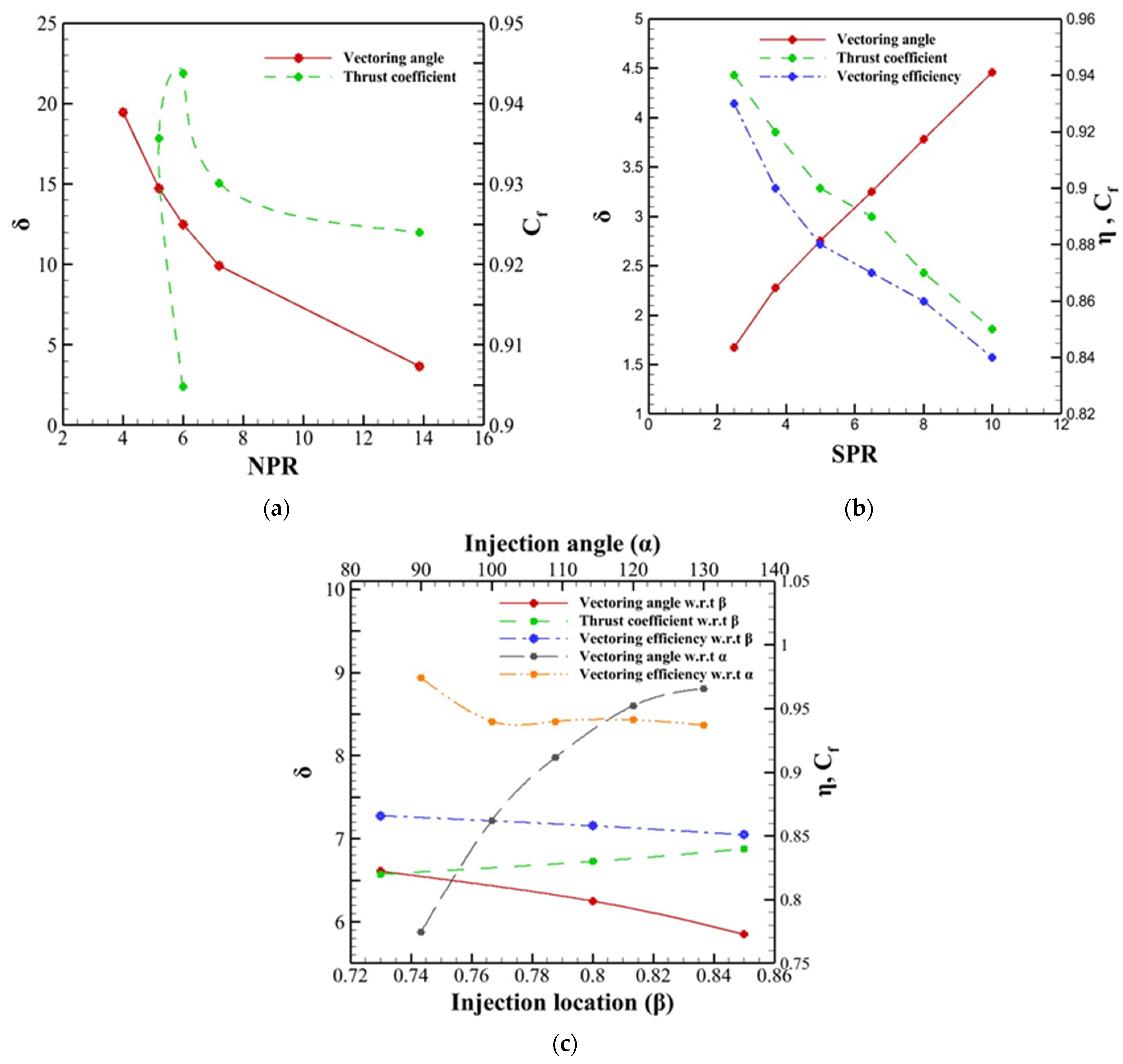
| 2019 | Numerical study on the shock vector control in a rectangular supersonic Nozzle | 3D rectangular nozzle | J = 0.1–0.89 X/L = 0.73–0.85 Λ = 45°–135° | Fluent/SST k-ω Model grid cells = 4.6 atm = 300 k | Increasing J and X/L ratio caused an increase in TV angle. The largest deflection angle was achieved when the injection location moved upstream and decreased when it moved downstream. | [25] |
| 2020 | Theoretical and Numerical Analyses of Aerodynamic Characteristics on Shock Vector Control | 3D rectangular nozzle | NPR = 3–5 SPR = 2.49 | Fluent/SST k-ω Model = 101,325 Pa = 300 k | NPR had a positive effect on thrust coefficient, primary MFR and a negative impact on vectoring angle. Vectoring angle increased with increasing SPR. | [39] |
| Parameters | Effects | Ref |
|---|---|---|
| Collar radius | Collar radius directly affected the pitching angle and suction MFR whereas it inversely affected the thrust coefficient | [68] |
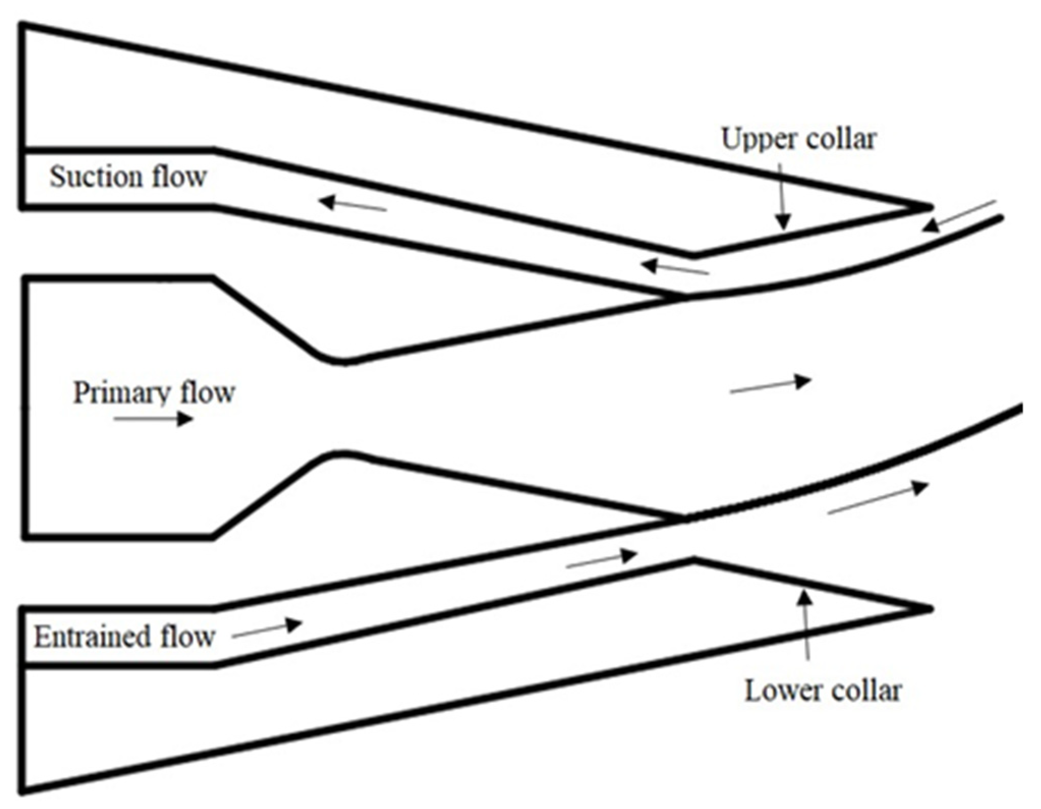
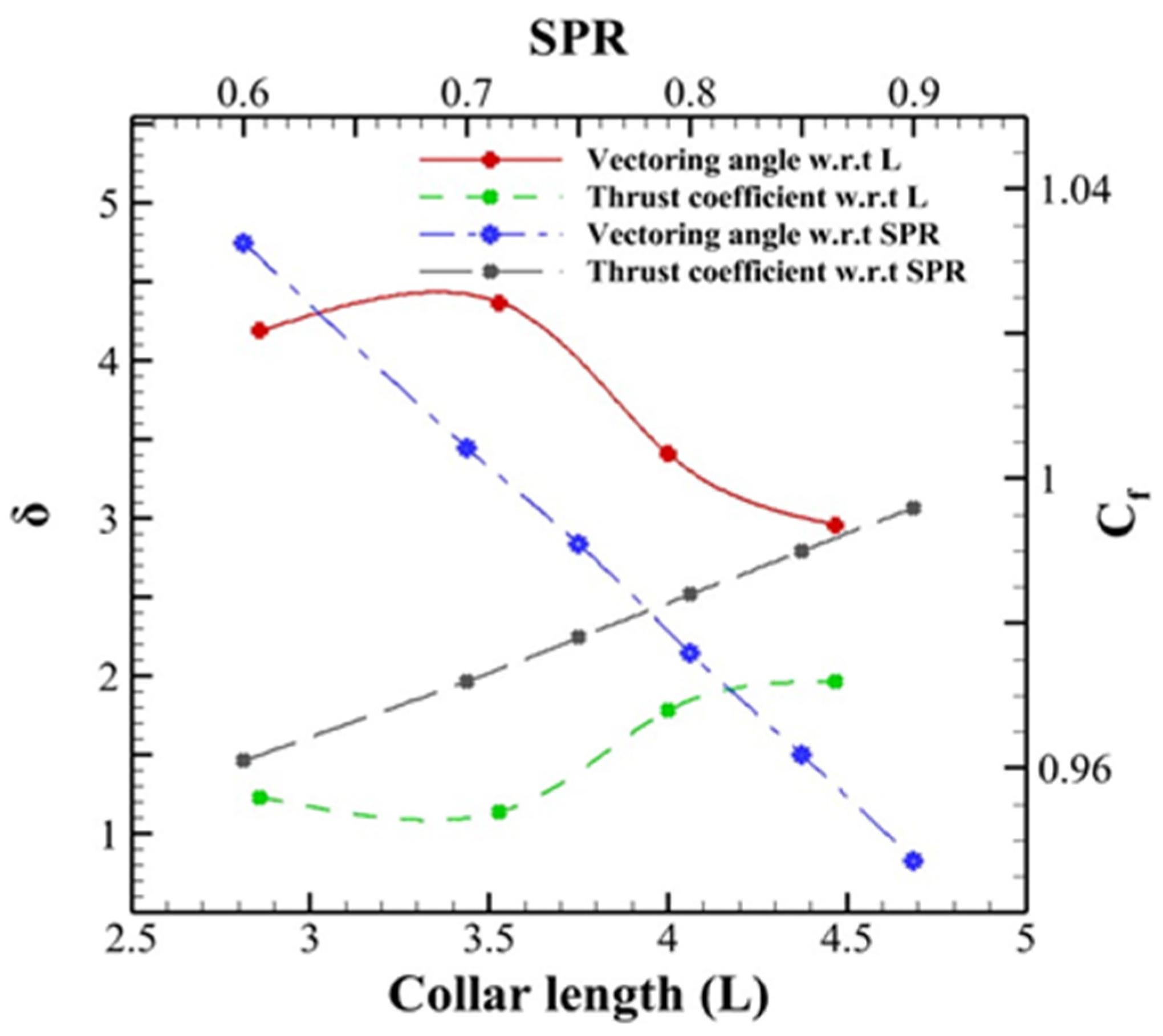
| Collar length | The length of the collar affected how side forces would act on the mainstream. The proper range affected the system’s performance. An excessively long collar would lead to hysteresis length occurrence and unnecessary weight | [72] |
| Gap height | It had a direct effect on pitching angle and an inverse effect on thrust coefficient, as well as suction MFR | [76] |
| NPR | The mass flow rate of primary flow increased whereas the mass flow rate of secondary flow decreased with increasing NPR. Additionally, NPR had a negative effect on the system thrust ratio (STR) | [77] |
| Year | Title | Model | Varying Parameters | Computational Setup and Details | Conclusions | Ref |
|---|---|---|---|---|---|---|
| 2017 | Numerical simulation of fluidic thrust vectoring in an axisymmetric supersonic nozzle | 2D nozzle | Collar length = 0.17–0.23 Slot width = 0.014–0.026 | Fluent/k-ε Model = 0.1–0.6 atm = 300 k | For larger collar length, the flow attached to upper collar wall. | [72] |
| 2017 | Investigation on Flow field Characteristics and Performance of Shock Vector Control Nozzle Based on Confined Transverse Injection | 3D nozzle | Coanda surface = 0.5–1.75, Gap height = 0.02–0.05 | Fluent/k-ε Model | Secondary gap height had a negative impact on TV angle. The dead zone appeared at low secondary MFR where TV angle was small. | [78] |
| 2017 | Numerical Investigation of Optimization of Injection Angle Effects on Fluidic Thrust Vectoring | 2D nozzle | NPR = 15–20 SPR = 0.6–0.9 | Fluent/k-ε Model 153,136 grid cells = 0.1–0.6 atm = 300 k | With constant SPR, NPR directly affected the primary MFR and inversely affected secondary MFR. | [64] |
| 2018 | Influence of Secondary Injection Parameters on Performance of Shock Vector Control Nozzle | 2D nozzle | Mach no = 0.1–0.8 | Fluent/k-ε Model 153,760 grid cells = 7.824 atm = 300 k | TV angle did not have a much influence under large Mach number. | [79] |
| 2019 | Fluidic Thrust Vector Control Using Shock Wave Concept | 2D nozzle | NPR = 15–20 SPR = 0.6–0.9 | Fluent/k-ε Model 153,136 grid cells = 300 k | When increasing or decreasing NPR and SPR, hysteresis phenomena occurred. For SPR = 0.8, the TV angle and secondary MFR increased with decreasing NPR. Additionally, for NPR = 17, the TV angle and the secondary MFR decreased with an increasing SPR | [80] |
| 2019 | Numerical study on the shock vector control in a rectangular supersonic nozzle | 3D nozzle | Gas source Case i. Both sides control joint closed Case ii. One side control joint open | = 5000 Pa = 300 k | Flow field was found symmetrical for case i. Primary flow was deflected in case ii. | [81] |
| 2020 | Theoretical and Numerical Analyses of Aerodynamic Characteristics on Shock Vector Control | 3D nozzle | NPR = 17 SPR = 0.8 Gap height = 0.28–0.53 | Fluent/k-ε Model = 17,225,251 Pa = 300 k | Collar radius had a positive impact on TV angle. As collar length increased, TV angle increased and then started decreasing. | [68] |
| Parameters | Effects | Ref |
|---|---|---|
| Secondary Flow blowing rate | Increasing the secondary flow blowing rate results in an increased vectoring angle | [90] |
| Secondary flow height | With an increase in secondary flow height, the value of thrust vectoring angle decreases | [85] |
| MFR | It affects the TV angle once overcoming the dead zone | [87] |
| Coanda surface diameter | The prolongation period of the dead zone depends upon the diameter of the Coanda surface. Large diameter results in a short dead zone range and vice versa | [83] |
| Year | Title | Model | Varying Parameters | Computational Setup and Details | Conclusions | Ref |
|---|---|---|---|---|---|---|
| 2007 | Experimental and computational investigation into the use of co-flow fluidic thrust vectoring on a small gas turbine | 3D nozzle | Gap height = 1–2 mm RPM = 78,000–110,000 | Fluent/k-ε Model 471,700 grid cells = 0.1–0.6 atm = 300 k | Increasing the gap height for a constant secondary air mass flow rate reduces the TV angle. For a fixed geometry, enhanced shaft speed had a negative impact on TV angles. | [84] |
| 2007 | Multi-Directional Co-Flow Fluidic Thrust Vectoring Intended for a Small Gas Turbine | 3D nozzle | Single section = 0% and 6.8% Two sections = 20.96% secondary MFR | Fluent/k-ε Model 684,400 grid cells | For yaw control a single secondary section can be used, however, for pitch control a two secondary section provided an efficient TV angle. | [87] |
| 2016 | An investigation of empirical formulation and design optimization of co-flow fluidic thrust vectoring nozzles | 3D nozzle | RPM = 58,000–98,000 | Fluent/k-ε Model 520,000–690,000 grid cells | The optimized nozzle design provided 32% improved TV angle over conventional nozzles. | [88] |
| 2017 | Fluidics Thrust Vectoring Using Co-Flow Method | 3D nozzle | Gap height = 0.0296–0.1176, Coanda diameter = 1.176–3.529 | Fluent/k-ε Model | TV angle increased with decreasing gap height. Dead zone length depended upon Coanda diameter. | [85] |
| 2018 | Bidirectional Thrust Vectoring Control of a Rectangular Sonic Jet | 3D nozzle | NPR = 2–4 | On–off operation of two control valves connected to two secondary chambers. = 288 k | It achieved a TV angle greater than 60° at limited NPR range of 2.3 to 2.6. The TV angle then decreases for NPR > 2.7. Thrust losses can be minimized by opening both valves to atmospheric pressure which eliminates the shock structure within the nozzle. | [91] |
| 2018 | Directional Control of a Jet Using the Coanda Effect | 2D nozzle | Secondary jet speed = 0–70 m/s | = 5000 Pa = 300 k | TV angles were unaffected for jet speed over 60 m/s. Increasing the secondary jet velocity increased the jet deflection and changed the jet velocity profile shape. | [90] |
| 2018 | Computational and experimental investigation of fluidic thrust vectoring actuator | 3D nozzle | Exit height = 0.026–0.080, Coanda radius = 0.33–0.5 | CFX/k-ε Model 0–0.13 | TV did not occur at dead zone (msec/mpri < 0.04). For msec/mpri > 0.118 in saturation region, no increase in vectoring angle occurs. Between 0.04 < msec/mpri > 0.118, increasing secondary flow enhanced TV angles in control region. | [92] |
| Parameters | Effects | Ref |
|---|---|---|
| Cavity length | Cavity length had a negative impact on thrust ratio and discharge coefficient but had a positive effect on TV angle and efficiency | [108] |
| Convergence angle of the cavity | Increased Cavity convergence angle would increase TV angle and decrease thrust ratio and discharge coefficient | [19] |
| Expansion ratio | Increasing expansion ratio and NPR resulted in an increased cavity length | [116] |
| NPR | Increasing NPR would decrease TV angle with increase thrust ratio and thrust efficiency | [120] |
| Flap length | Decreasing flap length resulted in an increased expansion ratio and NPR | [110] |
| Year | Title | Model | Varying Parameters | Computational Setup and Details | Conclusions | Ref |
|---|---|---|---|---|---|---|
| 2014 | Experimental and Numerical Investigations of a Bypass Dual Throat Nozzle | 2–3D nozzle | NPR = 1–16 | Fluent/realizable k-ε Model, 44,778 grid cells Pa = 101,325 Pa, Ta= 300 k | NPR had a negative impact on TV angle. Thrust coefficient was found to decrease with increasing NPR. Best performance was recorded at NPR = 4 | [20] |
| 2015 | Dynamic Experimental Investigations of a Bypass Dual Throat Nozzle | 3D nozzle | NPR = 3–10 | Cold blowdown wind tunnel facility | At NPR = 3, 5, and 10, BDTN was able to achieve 50 deg/s, 40 deg/s, and 34 deg/s dynamic vector rate. | [121] |
| 2019 | Computational study of axisymmetric divergent bypass dual throat nozzle | 2–3D nozzle | Expansion ratio = 1.1025–1.5625 Radius ratio = 1.05–1.25 | Fluent/Spalart Allmaras Model 2.3 × 10⁶ nodes Ppri = 405,300 Pa, Psec = 607,950 Pa Pa = 101,325 Pa, Ta= 300 k | The effect of radius of throat on TV performance was relatively small. Increasing the bypass width enhanced the thrust and discharge coefficients. | [128] |
| 2020 | Design and Preliminary Analysis of the Variable Axisymmetric Divergent Bypass Dual Throat Nozzle | 3D nozzle | NPR = 4.47 i. After burning state ii. Non-afterburning state | Fluent/Spalart Allmaras Model 2.3 × 10⁶ nodes Paf = 453,138 Pa, Pin = 453,138 Pa Pa = 101,325 Pa, Taf = 2000 k, Tin = 904 k | Non-after burner state reported increased TV angles than afterburning states for both improve geometry scheme. Discharge and thrust coefficients were approximately equal for both nozzle states. | [129] |
| 2020 | Experimental evaluation and numerical simulation of performance of the bypass dual throat nozzle | 3D nozzle | NPR = 2–16 Bypass position = 0–0.17 | Fluent/RNG k-ε Model 855,000 grid cells Pa = 101,325 Pa, Ta = 300 k | Increasing bypass position leads to increased TV efficiency. The thrust coefficient was reported in range of 0.85–0.93 with increasing NPR from 2 to 4. | [125] |
| 2023 | Numerical Investigation on the Thrust Vectoring Performance of Bypass Dual Throat Nozzle | 3D nozzle | NPR = 2–10 Bypass angle = 35°–90° Convergence angle = 22°–37° Bypass width = 2.6–5 mm | Fluent/RNG k-ε Model, Pa = 101,325 Pa, Ta = 300 k | Increasing the bypass angle has a positive impact on vectoring angle and efficiency. Convergence angle has no significant impact on vectoring performance. | [130] |
| Evaluation Criteria | SVC | BSVC | CFC | Co flow | TSC | DTN | BDTN |
|---|---|---|---|---|---|---|---|
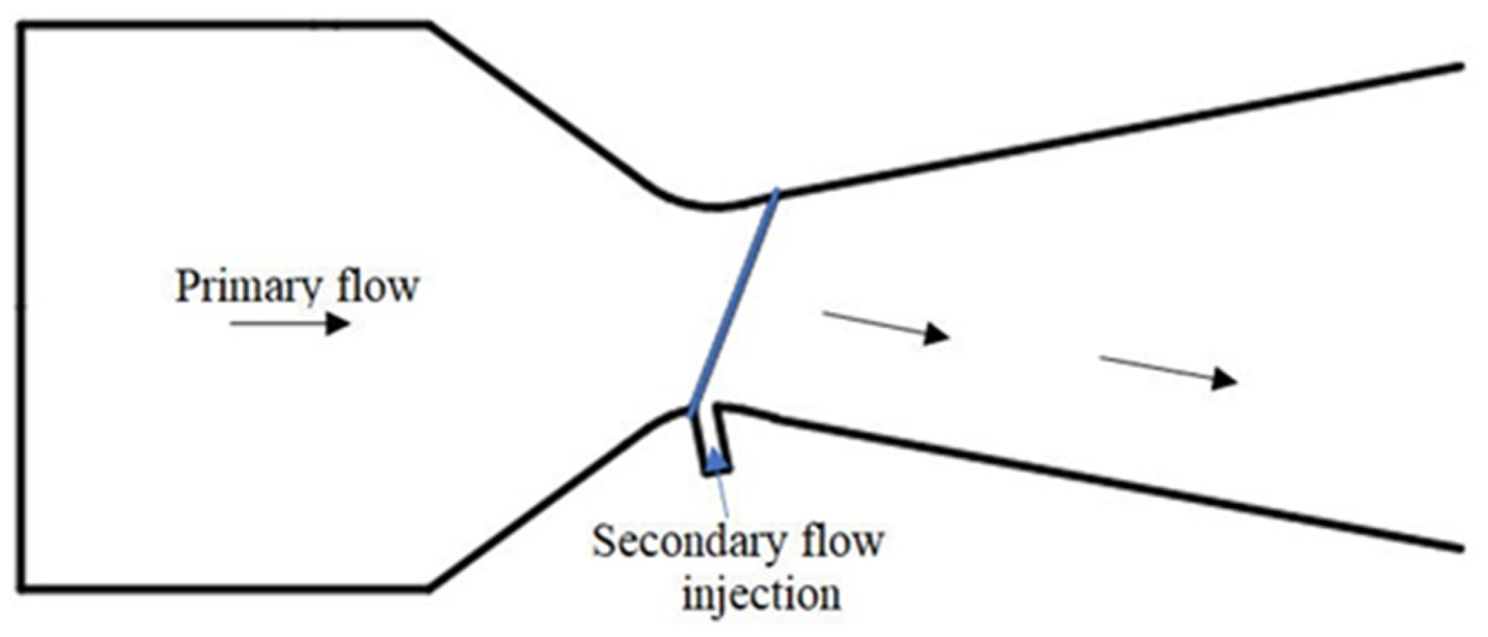
| Design | Secondary flow injection in the supersonic region | A bypass flow injection in the divergent section | Secondary flow penetrated in the opposite direction of primary flow | Secondary flow penetrated along with the primary flow | Asymmetrical injection in the throat | Secondary flow is injected in the upstream minimum area | Bypass is introduced at the upstream throat |
| Impact on system | Reduces the maximum resultant thrust | No secondary injection requirement | No moveable parts for flow vectoring | Minimal momentum loss | No shock losses | Enhanced performance due to the cavity regions | No thrust losses |
| Implementation | Readily integrated into existing systems | Readily integrated into existing systems | Critical design Required for optimum performance | Critical design Required for optimum performance | Readily integrated into existing systems | Readily integrated into existing systems | Readily integrated into existing systems |
| TV angle | Large | Small | Large | Small | Small | Large | Large |
| Thrust coefficient | Lower | Higher | Higher | Lower | Higher | Higher | Higher |
| Thrust efficiency | Higher | Lower | Higher | Lower | Higher | Higher | Higher |
| Thrust losses | Higher | Higher | Higher | Lower | Lower | Lower | Lower |
| Negative consequences | Large thrust losses | Complex flow field | Hysteresis, suction source and integration problems | Limitation on TV angle | Low performance | High-pressure secondary injection | No negative consequences predicted until now |
| Potential problem | High differential pressure losses. In fully expanded conditions, the oblique shock wave is less effective in deflecting the primary flow | Shock waves induced at a higher SPR are insufficient for vector operation because they interact with the opposite wall at a higher bypass injection angle | Connection of the main jet to the suction collar | Connection of the main jet to the suction collar | Vectoring and jet area control are possible simultaneously, but it can be difficult to separate them | TV operation adversely affects discharge coefficient | So far, no potential problems were listed in the literature |
Disclaimer/Publisher’s Note: The statements, opinions and data contained in all publications are solely those of the individual author(s) and contributor(s) and not of MDPI and/or the editor(s). MDPI and/or the editor(s) disclaim responsibility for any injury to people or property resulting from any ideas, methods, instructions or products referred to in the content. |
© 2023 by the authors. Licensee MDPI, Basel, Switzerland. This article is an open access article distributed under the terms and conditions of the Creative Commons Attribution (CC BY) license (https://creativecommons.org/licenses/by/4.0/).
Share and Cite
Afridi, S.; Khan, T.A.; Shah, S.I.A.; Shams, T.A.; Mohiuddin, K.; Kukulka, D.J. Techniques of Fluidic Thrust Vectoring in Jet Engine Nozzles: A Review. Energies 2023, 16, 5721. https://doi.org/10.3390/en16155721
Afridi S, Khan TA, Shah SIA, Shams TA, Mohiuddin K, Kukulka DJ. Techniques of Fluidic Thrust Vectoring in Jet Engine Nozzles: A Review. Energies. 2023; 16(15):5721. https://doi.org/10.3390/en16155721
Chicago/Turabian StyleAfridi, Saadia, Tariq Amin Khan, Syed Irtiza Ali Shah, Taimur Ali Shams, Khawar Mohiuddin, and David John Kukulka. 2023. "Techniques of Fluidic Thrust Vectoring in Jet Engine Nozzles: A Review" Energies 16, no. 15: 5721. https://doi.org/10.3390/en16155721