Article

Research on Stability Control of Shields at Working Face with Large Dip Angle

1
College of Energy and Mining Engineering, Shandong University of Science and Technology, Qingdao 266590, China
2
Information Institute of the Ministry of Emergency Management of the PRC, Beijing 100029, China
3
College of Mining Engineering, Taiyuan University of Technology, Taiyuan 030024, China
*
Authors to whom correspondence should be addressed.
Energies 2023, 16(15), 5813; https://doi.org/10.3390/en16155813
Submission received: 1 June 2023 / Revised: 23 July 2023 / Accepted: 2 August 2023 / Published: 4 August 2023

Abstract

:
Coal is the main energy source in China. As flat and shallow coal seams are being depleted, adverse coal seams such as inclined and steeply inclined coal seams account for larger proportion of seams that are mined. For these coal seams, instability such as slip and tipping of mining equipment due to the large inclination is a significant challenge for the productive operation of intelligent or smart mines. Therefore, this paper serves to provide some insights into improving their stability. In this paper, research on the anti-tipping and anti-slip technology of shields is carried out on an intelligent working face with a large dip angle. A mechanical model of “support-surrounding rock” was established. Through the analysis of the influence of the self-weight of the support on its stability and through theoretical analysis and field practice, it was found that the critical tipping angle of the support in the free state is 27.8, the critical slip angle is 16, and the support is more prone to slip in the free state; the shields in the middle of the working face are the key area for stability control. Suitable technical measures are taken to ensure the stability of the supports, which provides the management and practical basis for safe and efficient mining in the intelligent working face with a large dip angle.

1. Introduction

Coal is the primary energy source in China as well as many other countries such as India, U.S. Germany, Poland, Australia, South Africa, etc. The sourcing of energy is highly dependent on coal mining. Efficient extraction of coal seams that are easily extracted such as flat and shallow coal seams leads to increasing scarcity of those coal seams. Therefore, unmined coal reserves are more complex and adverse, and inclined and steeply inclined coal seams account for a larger proportion of mined coal seams. This shift presents unique challenges and necessitates research into addressing the stability and safety concerns associated with these seam types. As early as the 1970s–90s, the Soviet Union, U.S. Germany, Czech Republic, India, etc., carried out some research on mechanized mining with large dip angles and developed various kinds of fully mechanized mining supports and shearers applied to steep coal seams, which basically established the scientific and technological foundation of steep coal seam mining [1,2,3].
Mining of coal seams with large dip angles has been widely practiced and studied for about half a century. Mechanization and mining design are very important for their safe and efficient mining. In recent years, the successful mining of Huafeng Coal mine, Tangshan Coal Mine, and other mines with a large dip angle and sharp dip fully mechanized mining face indicates that the comprehensive mechanized mining technology of this kind of coal seam has been relatively mature and is in the comprehensive popularization stage [4,5,6]. In recent years, intelligent shields or support systems have increased efficiency and safety in coal mining operations. They can monitor and adjust the real-time posture of shields, which can further benefit the stability and safety of panels in coal seams with a larger dip angle.
Much progress has been made regarding the mining of inclined and steep coal seams. Alejano et al. [7] described a subsidence estimation methodology using the Finite Difference Method (FDM) numerical modelling technique to predict subsidence troughs due to flat and inclined coal seam exploitation and the method has been developed significantly over the past two decades. Ma et al. [8] carried out FLAC2D modelling to study the stress and displacement change of overburden strata caused by steeply inclined coal seam mining with a fault against the Zhaogezhuang Mine, Kailuan Group. A new model for estimating rock pressure induced in excavation/cut in sedimentary rock was developed by Ching et al. [9]; in this model, sliding along parallel bedding planes as well as random friction angles on these bedding planes was taken into account. Xin et al. [10] studied the characteristics of roof movement of inclined coal seam top coal and a mechanical model of support and surrounding rock stability was established. Lin et al. [11] carried out a study on failure modes of openings in a steeply bedded rock mass and found four typical failures categories. Gao [12] investigated the width of the non-elastic zone of a coal pillar in an inclined seam using the limiting equilibrium method considering the nature of plastic softening. Using infrared thermal imaging technology, Sun [13] carried out a physical modeling study on the floor heave of a roadway excavated in a ten-degree inclined strata with a large cover depth. Das et al. [14,15,16] carried a number of studies regarding underground workings and coal pillars through multiple methods including numerical modelling, the theoretical ubiquitous joint model, etc. Foroughi [17] and Jessu [18,19] discussed some insights into coal pillar stability in inclined coal seams. Using micro-seismic monitoring, Sun et al. [20] performed research on failure characteristics of inclined coal seam floors. Wang et al. [21] studied the stress state of coal masses in working faces being subjected to coal bursts in steeply inclined coal seams. Çelik et al. [22,23,24] carried out a number of studies on steeply inclined thick coal seams including longwall top coal caving efficiency and top coal drawn height using physical modelling. Tu et al. [25] summarized the status quo of fully mechanized mining technology for steeply inclined coal seams in China. Using discrete elements, Klishin et al. [26] put forward a mathematical model to study the gravity flow of granular material coal discharge in three-dimensional formulation in mechanized steep and thick coal mining. Kostyuk et al. [27] pointed out that the problem to search for variants for the development of steep thick coal seams is of high interest and they proposed a number of methods for variants for managing the workings’ roof by caving or laying the worked-out space. Klishin et al. [28] offered an underground geotechnology for thick, flat, and steep coal beds based on the controllable force-fed extraction of pre-broken coal using a re-designed powered roof support. Selyukov et al. [29] emphasized the well-known technological solutions of using a block lateral mining method with overburden storage in the worked-out space in developing the most inclined and steep coal deposits in the Central and Northern Kuzbass, Western Siberia, Russia. Rak [30] presented mechanized sublevel caving systems for winning thick and steep hard coal beds. Kolesnikov et al. [31] studied the features of excavation and loading equipment of various types in the development of inclined and steep beds. Using SDLs, Mohammad et al. [32] carried out a study on the design of rhombus coal pillars and support for roadway stability and mechanizing loading of face coal in a steeply inclined thin coal seam. Considering geotechnical uncertainties, Kumar et al. [33] presented a design of stable parallelepiped coal pillars. Pham et al. [34] carried out a justification of spatially planned solutions and determination of the dimension block in the working of medium thick inclined coal seams with a room and pillar system. Zhao et al. [35] discovered fractal characteristics of methane migration channels in inclined coal seams. Nikitenko et al. [36] studied the robotic complex for the development of thick steeply inclined coal seams and ore deposits. Asadi et al. [37] developed a new mathematical model to predict surface subsidence due to inclined coal-seam mining. Using physical modeling, Erdem and Duran [38] proposed a model for extended bench casting in dipping coal seams. Through numerical analysis, Eremin et al. [39] carried out a study on pillar stability in longwall mining of two adjacent panels of an inclined coal seam. Using FEM, Mateusz and Tajduś [40] put forward a prediction of surface deformations induced by flooding of steeply inclined mining seams.
The above studies are important for the mining of coal seams with a large dip angle from many aspects. Despite the above endeavors, however, inclined and steeply inclined coal seams still encounter many problems, especially with the development of mechanization and intellectualization, as the mining efficiency of those coal seams is more challenging to uphold with the efficiency of mining machinery [41,42]. In addition, it is necessary to consider the specific geological conditions and to constantly solve problems based on theory and technology in order to achieve success in the field. Therefore, the extraction of a coal seam of the 4303S panel of Changcheng Coal Mine in Ordos, China with a large dip angle is studied in this paper to ensure efficient and stable mining of the intelligent working face. The study of this paper can provide a scientific basis for the stability control of shields at the working face, which is significant for high efficiency and high productivity of intelligent panels.

2. Engineering Background

2.1. The Panel

The 4303S panel is located in the fourth mining district at the +750 level in the East District, as show in Table 1 The coal seam mined is the 3# upper coal seam. To the east of the panel is the fifth mining district, and to the west is the return air roadway in the East District. To the south is the protective coal pillar for the ancient Great Wall, and to the north is the setup room of the 4303 (W) panel. As shown in Figure 1, the length of the panel along strike is 801~863 m, the width along dip is 140~147 m, the upper and lower mining elevations are +993.8~+759.2 m, and the vertical depth of the working face is 244.3~485 m.

2.2. Occurrence of the Coal Seam

According to the analysis of the actual exposure of the excavated roadway, the occurrence of the coal seam is stable, strike 185~195°, dip 94~95°, coal seam inclination is 33~42°, average inclination is 37.5°, coal seam thickness is 1.8~2.4 m, average 2.1 m, minable coefficient is 0.98, coefficient of variation is 25.98%. It is a stable medium thick coal seam. Density 1.5 t/m³. The details are shown in the Table 2.
The average total moisture content (Mad), ash content (Ad), float volatile content (Vdaf), total sulfur content (St, d), and calorific value (Qgr, d) of coal on top of three layers are 4.57%, 14.15%, 36.54%, 0.7%, and 28.5 MJ/kg, respectively. The coal is gas coal.

3. Mining Technology

The longwall retreating mining method is used for the panel. The roof strata cave is natural. Fully mechanized coal mining is adopted. When the working face is intelligent, remote centralized control + local intervention patrol is adopted. Non-intelligent operation is undertaken via manual normal operation. In all cases, an MG300/730-WD double-drum shearer is used for unloading and loading, and the circulating progress of the working face is 0.6 m. The coal is transported by SGZ730/630 scraper conveyer and the roof is supported by ZY6000/13/27D shield hydraulic support on the working face. The construction sequence is as follows: cutting coal → moving frame → moving conveyer.

4. Stability Analysis of Hydraulic Supports and Conveyor

The 4303S panel’s dip angle is large, and thus working face equipment has the risk of sliding and tipping. Therefore, the “support-surrounding rock” mechanical model is established, the free state and working state of the supports are calculated and analyzed, and the specific mechanical relationship affecting the stability of the support is obtained. Based on this, the corresponding support anti-tipping and anti-slip technology is developed to realize the stability control of the equipment of the fully mechanized caving surface with large dip angle in order to ensure the safe and rapid advance of the fully mechanized caving surface with a large dip angle [4,5].
The mechanical analysis of hydraulic support with large dip angle is carried out through the analysis of the influence of the support weight on the stability of the support itself, the influence of the strike angle is considered in the trend stability, and the influence of the trend angle is considered in the trend stability. The mechanical analysis of a single support is divided into normal mining period and special period (roof pressure, roof collapse, fault, sheet serious, etc.). This differentiation of periods is due to the support of the roof pressure being different; the support uses different force boundary conditions and stability analysis in order to find a reasonable method to improve the stability of the support, thus providing a basis for roof stability control.

4.1. Mechanical Model of “Support and Surrounding Rock”

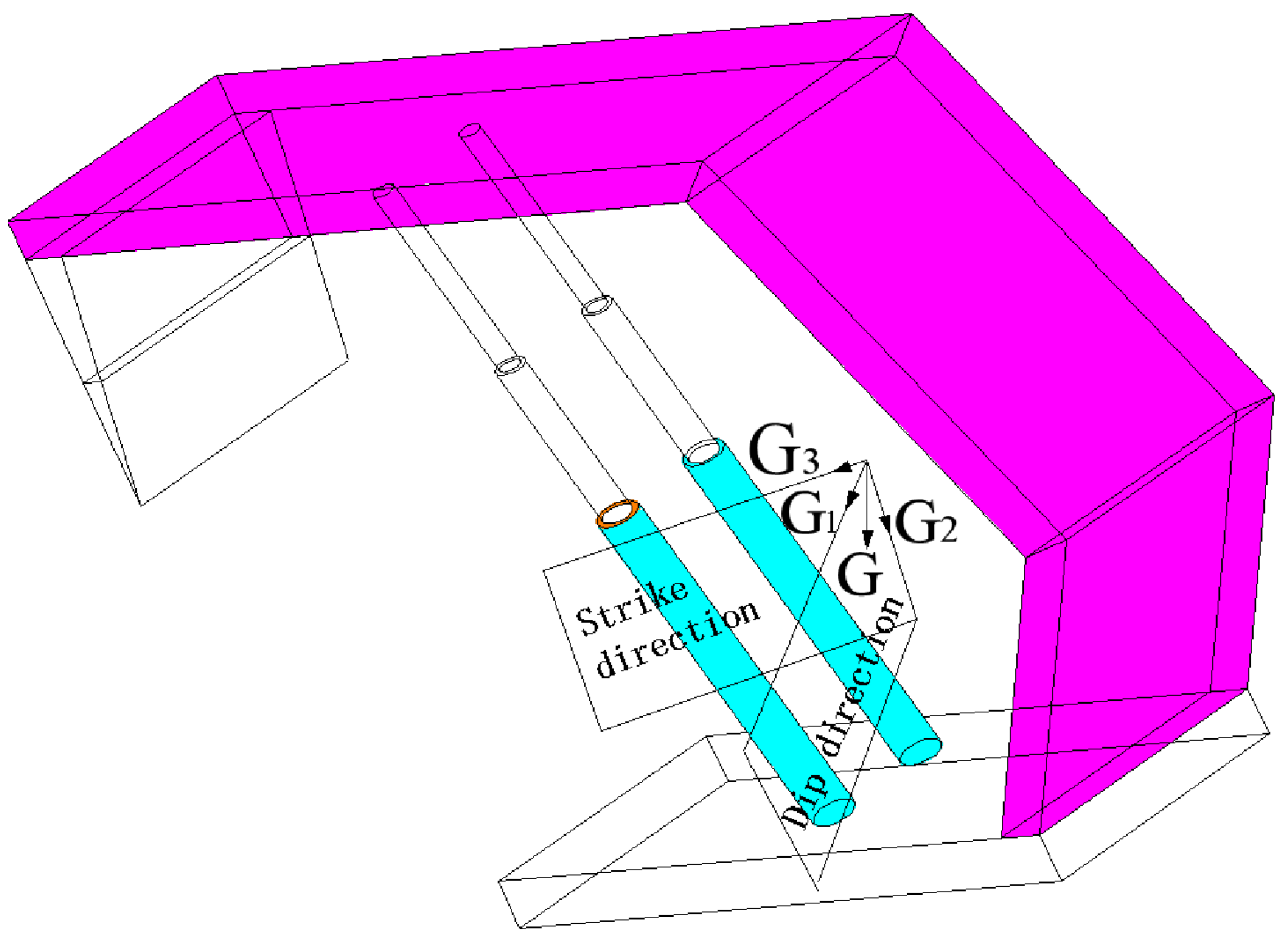
The stability of the hydraulic support is reduced due to the influence of the inconsistent movement of the “roof-support-floor” and the dip angle. To this end, a mechanical model of a shield affected by its self-weight was established, as shown in Figure 2. According to this mechanical model, stability analyses of the shield in dip and strike directions were carried out.
It can be seen from Figure 2 that the component forces of the dead weight G of the support parallel to the bottom surface of the support, namely G1 and G3, pose a certain threat to the stability of the support. The direction of G1 and G3 is perpendicular. Due to the limitation of the mechanical analysis method, the stability of the support must be analyzed from the two directions of the panel dip and strike. Because the support stability is the joint action of the two angles of the dip and strike, if G1 and G3 are substituted into the calculation of the dip and strike of the support, the influence of the striking angle and the dip angle on the stabilities along strike and dip will be ignored. This factor is ignored in the past analysis of support stability.
In the analysis of support stability, in order to make the calculation results more accurate (considering the influence of dip angle and strike angle on the stability of the support) and in order to ensure a certain safety factor and convenient calculation, the resultant values of G1 and G3 were substituted into the mechanical calculation of the dip and strike of the support as G1 and G3, respectively.
According to the geometric relation shown in Figure 2 and the above simplification, G2 = G·cosα·cosβ; G1 = G3 = G × 1 cos 2 ( α ) + cos 2 ( β ) . α is the dip angle of the panel; β is the angle of upward or downward mining. The hydraulic support parameters of the panel are shown in Table 3 (because the panel adopts the modified support, the setting resistance of the support is lower than the designed one).

4.2. Mechanical Analysis of Support along the Dip

(1)
Free state mechanical analysis of the support
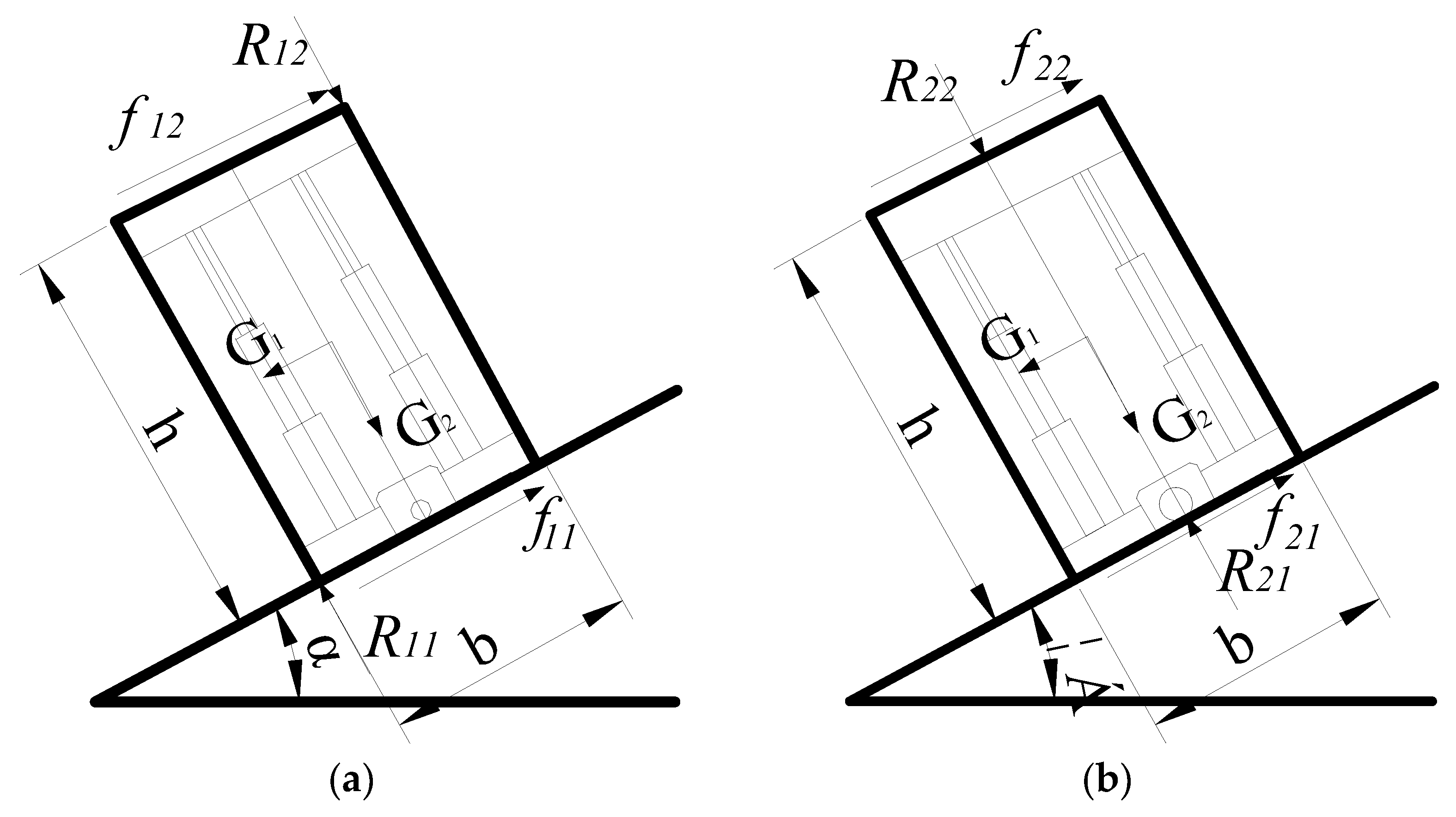
For a longwall panel with a large dip angle, because of the self-weight component of the support and the thrust force (gravity component) exerted on the top beam, the support often slides and tips along the dip. For the convenience of derivation, the influence of the working face conveyor, shearer, and adjacent frame on the sliding of support is ignored for simplification, and the state of a single support inclined to free on the working face can be simplified into the mechanical model as shown in Figure 3.
(2)
Analysis of support tipping model
As shown in Figure 3a, when the support is in a critical state of tipping instability,
G 1 × h 2 = G 2 × b 2
where h, b are the support height and width, respectively, and α is the coal seam dip angle (°).
The simplification is as follows:
α = arccos ( h cos ( β ) b 2 + h 2 )
According to Equation (2), in the free state, the critical tipping angle of the inclined direction of the support is inversely proportional to the mining height h, proportional to the width of the support b, and inversely proportional to the strike angle β.
According to Equation (2), the critical tipping angle of the support at different mining heights and angle of mining downdip (updip) is shown in Table 4 when the support is free. The width of the support is 1.5 m.
Table 4 The inclined critical tipping angle of different mining heights and inclined (upward) mining angles under the free state of the support.
It can be seen from Table 4 that mining height and angle of mining downdip (updip) are important factors affecting the critical tipping angle, and the variation of mining height and mining angle has a significant influence on the critical tipping angle. In order to improve the stability of the support, the layout of the panel should lower the angle of mining downdip (updip) as much as possible.
After the mining technology of the working face is selected, the mining height of the coal seam is also determined, and the strike angle of the panel is also determined with the roadway layout. At this time, the critical tipping angle of the support can only be increased by increasing b (support width). Immediate increment of support width is beneficial to the stability of the support itself.
The mining conditions of panel are as follows: mining height h is 2.8 m, support width b is 1.5 m, friction coefficient between metal and coal seam is 0.35~0.4, μ is 0.3 conservatively, and angle of mining downdip (updip) is 5°. It is calculated that the critical tipping angle of the support in free state is 27.8°. The dip angle of the panel is 8°~30°, so corresponding anti-tipping measures should be taken in the area where the local dip angle is greater than 27.8°.
(3)
Analysis of support slip model
As shown in Figure 3b, the critical state requirements for sliding support are as follows:
f 21 = G × 1 cos 2 ( α ) cos 2 ( β )
So, this simplifies f21 = µ × G cos(α)cos(β) to
α = arccos ( 1 cos β 1 + μ 2 )
where μ—friction coefficient between the support and the roof and floor.
It can be seen from Equation (4) that the critical slip angle of the support on the panel is inversely proportional to the strike angle β, and proportional to the friction coefficient between the support and the floor.
According to Equation (4), the critical slip angle of the support in the inclined free state under different mining angles is shown in Table 5. The friction coefficient is 0.3.
As can be seen from Table 5, the angles of mining downdip (updip) is an important factor affecting the stability of the support. When substituted into the mining conditions of the panel (angles of mining downdip (updip) is 5°), the critical inclined slip angle of the support in the free state is 16°. The dip angle of the panel is 8°~30°, so the support will slip in the area where the local dip angle is greater than 16°, and corresponding anti-skid measures should be taken.
The critical angle of support sliding mainly depends on the friction coefficient between the floor and the support. In the actual mining of the panel, the coal seam floor is rock or coal, and its deformation is large, so it cannot be studied as a rigid body. Therefore, the support requires a larger width b to maintain good stability. In the field support selection, the width of hydraulic support is restricted by many mining conditions and support technical conditions. How to increase the width of the support to ensure the stability of the support becomes a difficult problem.
The stability of a single support is limited by the width of the support. It is impossible to increase the width of the support to ensure the stability of the support itself. However, the support of the working face is actually a whole, and the support is closely connected. If the support base of the panel is connected and the two supports are regarded as a whole, it is equivalent to a support whose support width becomes 2b, which greatly improves the stability of the support. Taking two supports as an example, if the two supports are connected together as one support, the mining height h of the coal seam is unchanged, while the width of the support is doubled and its stability is greatly improved. At the same time, each support is connected so that the friction force of the whole working face support is more uniform, and there will be no local poor sliding performance of the support (and the bottom plate soft and hard, humidity degree) to produce local slide, so as to produce a dynamic load on its support and affect the stability of the whole working face support. The above analysis shows that connecting the support base of the working face together, namely adding the support base adjustment device, is conducive to the anti-slip and anti-fall quality of the support.
(4)
Mechanical analysis of support working state
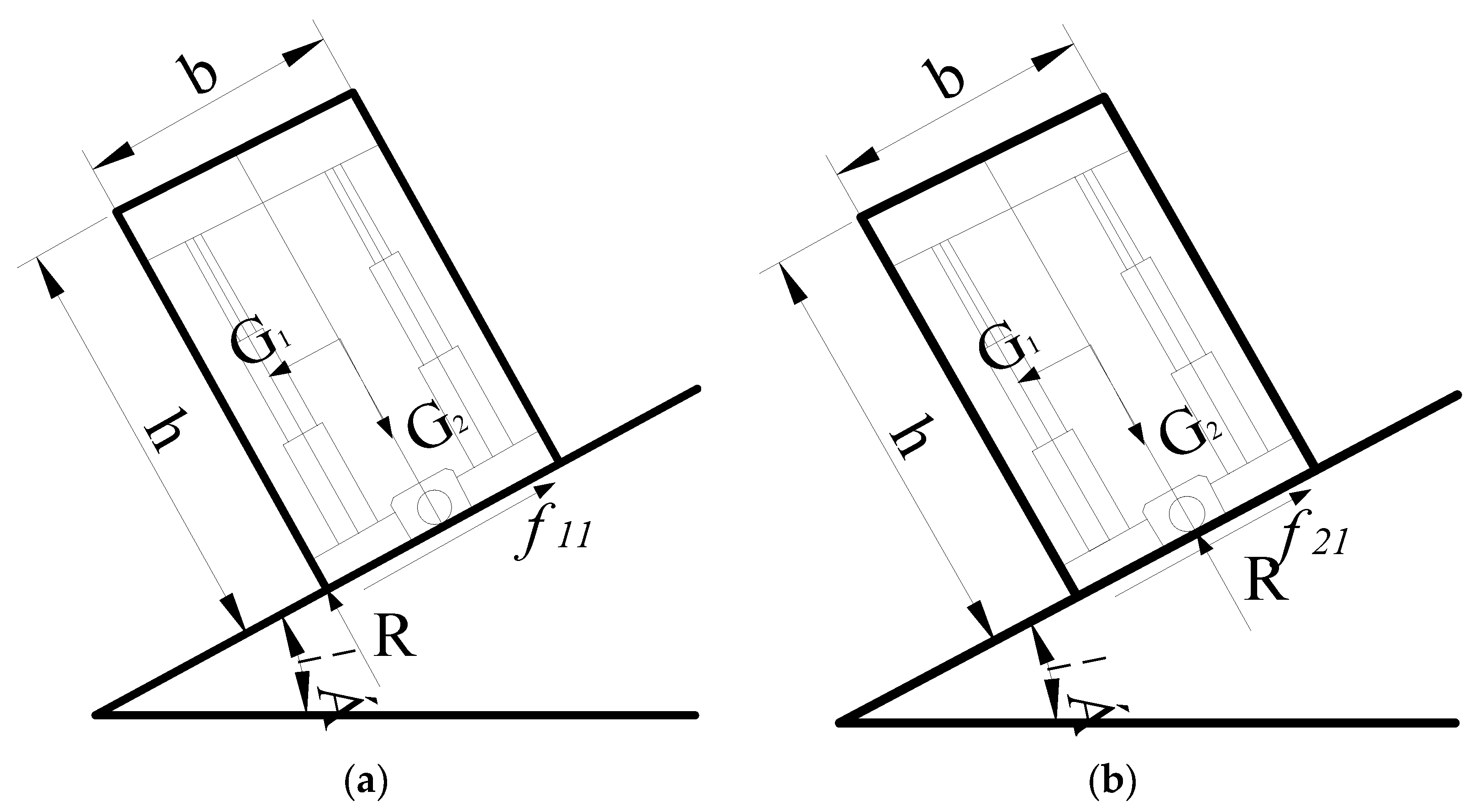
In the mining of the panel, the pressure of the roof on the support is also an important factor affecting the stability of the working face, especially the support with large dip angle. The stability of the support in the working state is quite different from that in the free state. The simplified mechanical model of the support in the working state is established, as shown in Figure 4.
According to Figure 4a, the force analysis of the support (Figure 4) can be concluded as follows:
f 11 + f 12 = G 1 R 11 = G 2 + R 12 f 12 = μ R 12 R 12 b + f 12 h + G 2 b 2 G 1 h 2 = 0
The critical tipping angle of the support in working state can be obtained by solving the following:
α = arccos h G 2 b 2 + G 2 h 2 4 R 12 2 ( μ h + b ) 2 2 R 12 b h 2 R 12 μ h 2 G b 2 + h 2 cos ( β )
  • where G—gravity on the support, kN;
  • R12—Working resistance, kN.
According to Equation (6), increasing the width of the support b and decreasing the height of the support h (mining height) will increase the critical dip angle of the working state of the support, which is conducive to the stability of the support on the working face. Its form and behavior are consistent with that of the support in the free state. The same measures are taken to prevent the support from slipping and tipping, that is, to increase the support base adjustment to improve the stability of the support. The critical inclination tipping angle of the working state of the support decreases with the increase in the dead weight G of the support and decreases with the increase in the mining downdip or updip angle of the support. Therefore, under the condition of ensuring the sufficient strength of the support with large dip angle, the appropriate reduction in the dead weight of the support is conducive to the anti-tipping of the support. Appropriately reducing the strike angle is beneficial to prevent tipping in the inclined direction of the working face support. According to the relation between α and μ in Equation (6), the critical tipping angle of the support along the dip increases with the increase in the friction coefficient μ between the support and the floor; that is, increasing the friction coefficient between the support and the floor is conducive to the anti-tipping of the support along the dip. According to the relationship between α and R12 in the formula, when the support force is increased, the critical tipping angle of the support will increase; that is, increasing the support’s support force is conducive to the anti-tipping of the support.
By putting the mining height of the working face, support gravity (G = 200 kN), and support’s support force (initial support force 3958 kN, working resistance 4650 kN) into the Equation (6), the calculated critical tipping angle does not exist under this condition, so the support will not tip under the initial setting and working state.
The critical state of the support sliding model is shown in Figure 4b:
f 21 + f 22 = G 1 R 21 = G 2 + R 22 f 21 = μ R 21 R 22 b 2 + f 22 h + G 2 b 2 G 1 h 2 R 21 b 2 = 0
The solution can be obtained by the following:
α = arccos R 22 + 4 G 2 μ 2 + G 2 4 R 22 2 μ 2 4 μ 2 + 1 G cos ( β ) R 22 G cos ( β )
When the support is in the initial setting state, R22 is the initial setting load; when the support is in the working state, R22 is the working resistance. According to Equation (8), increasing the support force of the support, increasing the friction coefficient between the support and the roof and floor, reducing the dead weight of the support (under the condition of ensuring sufficient strength of the support), and reducing the strike angle are conducive to the anti-slip of the support along the dip.
The working face conditions are as follows: the weight of the support is 200 kN, the initial setting load is 3958 kN, the working resistance is 4650 kN, the friction coefficient is 0.3, and the tilt (updip) mining angle is 5°. It is calculated that the critical slip angle does not exist, so the support will not slip in the initial setting and working state.
According to the above analysis, during normal extraction of the panel, the critical tipping angle of the support in free state is 27.8°, and the critical slip angle is 16°. Therefore, the support is more prone to slip in free state. The support will not tip and slip when it is in the working state.

4.3. Stability Analysis of Support in Special Period

The roof of the working face is easy to collapse during periodic weighting and passing fault, resulting in the stability deterioration of the “support-surrounding rock” system. As shown in Figure 5, The deterioration of the system is mainly reflected in the breaking of the roof and the rotation of the main roof during periodic weighting, which brings great lateral stress to the support, seriously threatening the safe and normal production of the working face. It is necessary to analyze the stability of the support in the above special period so as to better control the stability of the support and the roof in the special period and ensure the safe production of the working face.
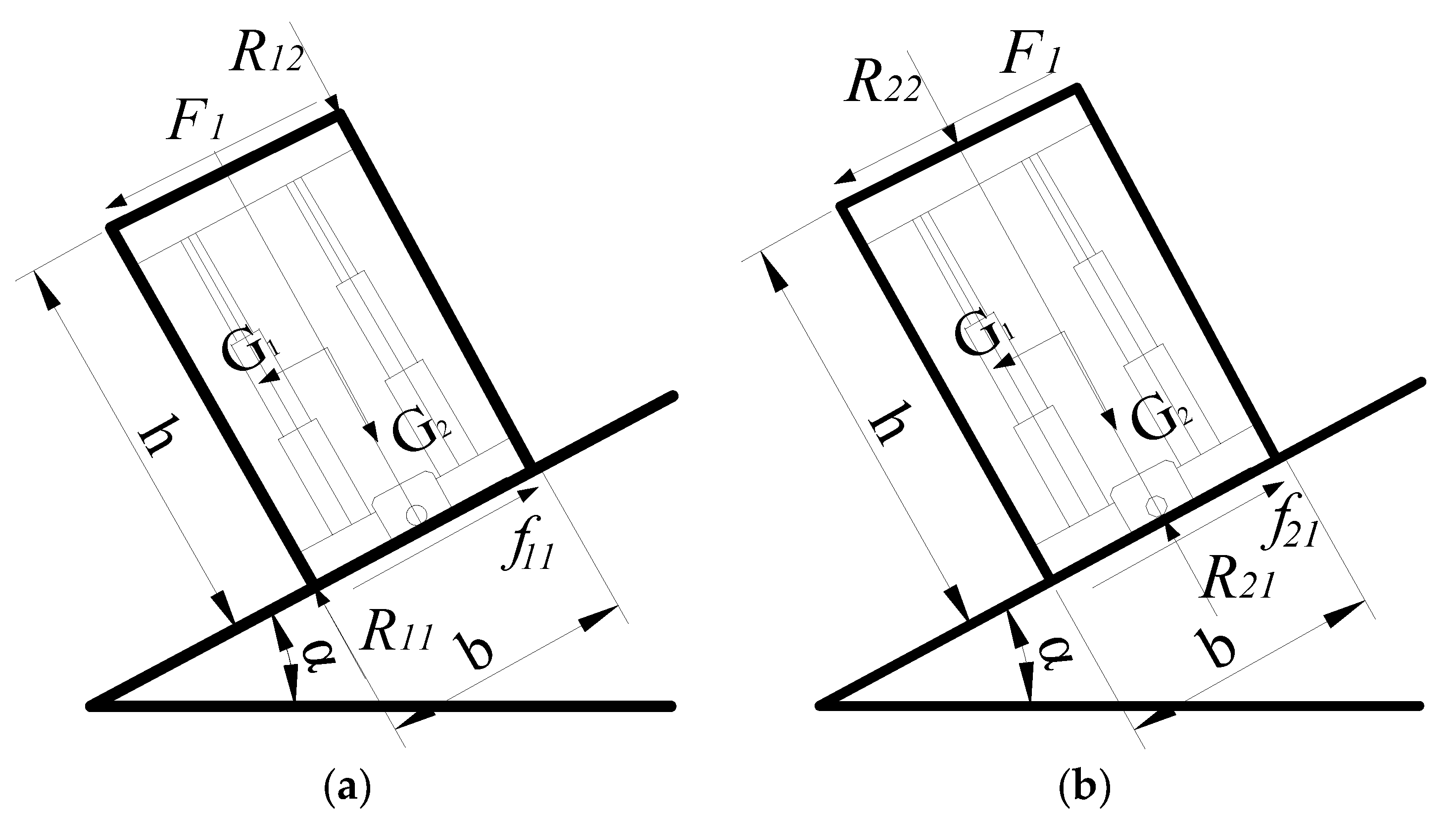
Based on the above analysis, a simplified mechanical model was established for the stability analysis of the support in special periods, as shown in Figure 6.
(1)
According to Figure 6a, the force analysis of the support tipping model in working state can be obtained in this way:
f 11 F 1 = G 1 R 11 = G 2 + R 12 f 11 = μ R 11 R 12 b F 1 h + G 2 b 2 G 1 h 2 = 0
The critical tipping Angle of the support in special working state can be obtained by solving the following:
α = arccos h G 2 b 2 + G 2 h 2 4 R 12 2 b 2 + 8 F R 12 b h 4 F 1 2 h 2 2 R 12 b 2 + 2 F 1 b h G b 2 + h 2 cos ( β )
According to Equation (10), under special conditions, the relationship between the critical tipping angle of support inclination and support dead weight, support width, mining height, support load, and strike angle is consistent with that in normal mining of working face. This is inversely proportional to the roof lateral stress F1.
In the analysis of support stability in this chapter, the lateral stress of the roof is treated as follows: the rock strata above the caving zone can form the structure, and the pressure of the support mainly comes from the weight of the rock strata within the caved zone. Caved zone height is taken as 2 times the mining height, that is, the caved zone height of working face is 5.36 × 2 = 10.72 m.
According to the working face conditions, the roof pressure borne by a single support is divided into two parts:
① immediate roof: γ × hi × hii × b = 25 × 5.27 × (4.3+1) × 1.5 = 1047.4 kN, where γ is the volumetric force, hi is the thickness of the immediate roof, hii straight is the length of the overhanging immediate roof, b is the width of the support.
② main roof: γ × hi × him × b = 25 × 10.7 × 10 × 1.5 = 4012.5 kN, γ is the volumetric force, hi is the main roof thickness, him is the periodic roof weighting interval, b is the width of the support. The total pressure of the roof to the support is 1047.4 + 4012.5 = 5060 kN, and according to resolution of force of the weight of the support (for example: the top of the cylinder is subjected to two perpendicular and parallel forces, and the tipping direction must be along the direction of the resultant force of the two forces. Because of the particularity of the support structure, it cannot be simplified in the direction of the resultant force for mechanical calculation, so the size of the resultant force is substituted into the component force of the support along the strike and dip, the calculation results will be more reasonable), if dividing the roof pressure perpendicular to the direction of the working face floor, parallel to the strike, parallel to the dip, and simplified by the same method, the lateral stress F1 = 5060× 1 cos 2 ( α ) + cos 2 ( β ) = 2570 kN can be obtained, and the critical support resistance can be calculated. The following calculations are calculated using this simplification, which will not be described here.
It can be obtained from the above analysis and calculation that the critical support resistance required by the support without tipping in the special period (dip angle) of the working face is 3279 kN.
(2)
The critical state of the support sliding model is shown in Figure 6b:
f 21 F 1 = G 1 R 21 = G 2 + R 22 f 21 = μ R 21 R 22 b 2 F 1 h + G 2 b 2 G 1 h 2 1 R 21 b 2 = 0 α = arccos μ F 1 μ 2 R 22 + G 2 μ 2 + 1 F 1 μ R 22 2 μ 2 + 1 G cos ( β )
From the foregoing analysis, the lateral stress of the roof F1 = 2570 kN is substituted into the calculation, and it is calculated that the critical slip angle does not exist when the support does not slip in the special period of the working face, meaning that the support will not slip.

5. Field Monitoring

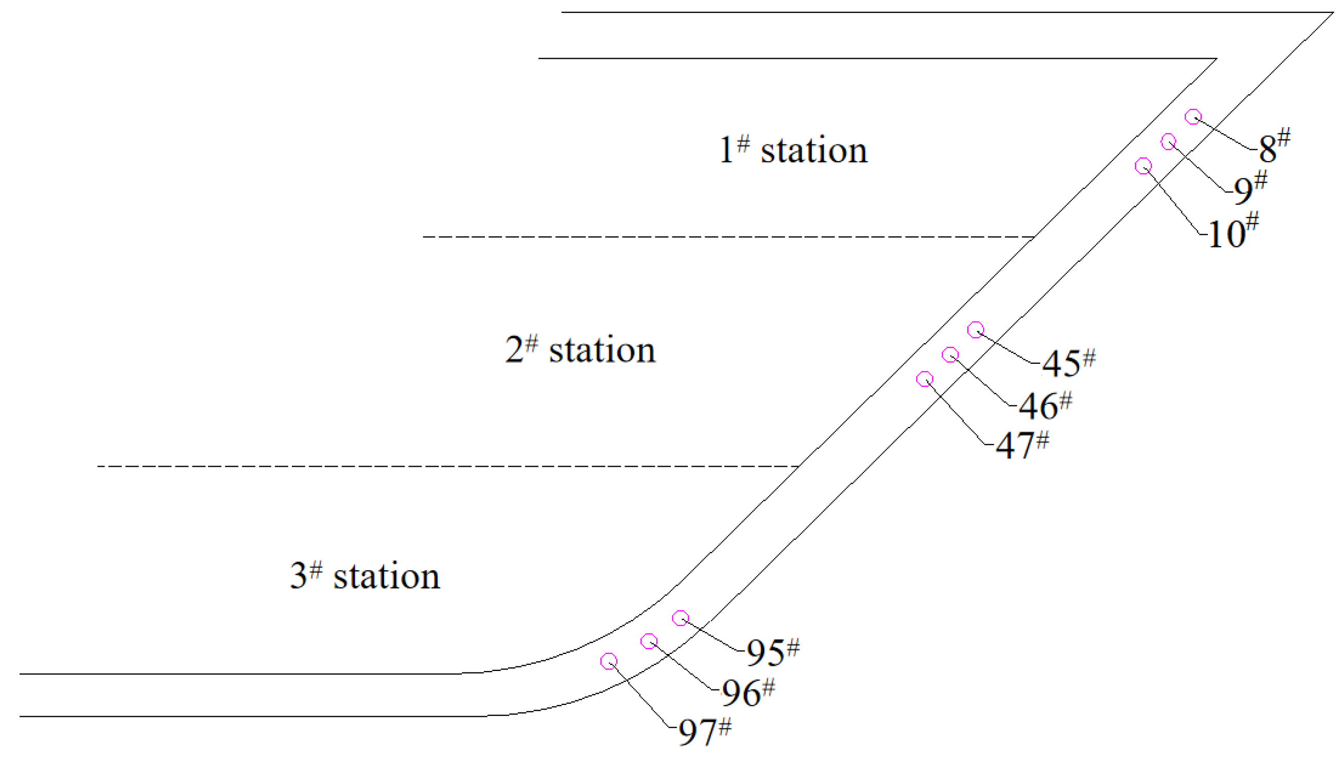
The loading of shields was monitored to further study the stability control of the shields. The monitored shields are shown in Figure 7 and data are given in Table 6, Table 7 and Table 8. It shows that the shields in the middle were subjected to the largest loading. The shields at the bottom were subjected to the smallest loading. The shields at the top were subjected to the moderate loading. This demonstrate that the theoretical modeling analysis agrees well with field data that the roof broke around the middle part of the panel leading to the most difficult stability control of shields in the middle. Therefore, the key stability control area of shields is in the middle.

6. Stability Assurance Technology for Equipment with Large Dip Angle

Through the above analysis, it shows that the hydraulic supports tip and slide due to the coal seam dip angle. See Figure 8.
Therefore, after theoretical modeling analysis and field practice test, the following technical measures are taken to ensure the stability of the support:

6.1. The Main Measures of Support Anti-Tipping

(1)
Ensure that there is no gap in the canopy of the support, so that it has no space to tip over; the side shield jack and the side push spring make the canopy more seamless, and always maintain enough correcting force to prevent tipping.
(2)
Add an adjusting jack between the adjacent supports, as shown in the Figure 9. When the support tips, the adjacent support supporting the roof is used as the fulcrum, and the position of the bracket is adjusted with the jack.
(3)
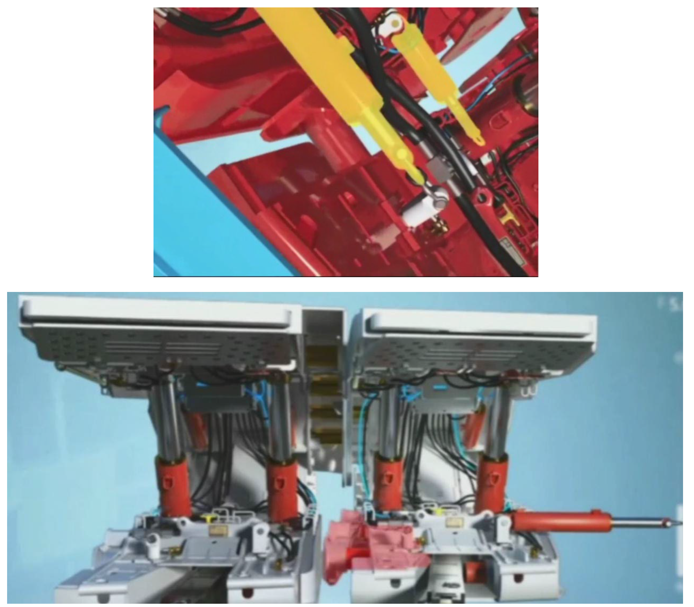
Add base adjusting jacks between the adjacent supports to restrict the tipping of a single support as shown in Figure 10. The effect of adding base adjusting jack is equivalent to connecting two supports together to become one. The width of the support is doubled, and its anti-tipping ability is greatly increased.
(4)
Add metal mesh between the canopy and the roof, because the friction coefficient between the metal mesh and the support is small, which can release the energy of the roof sliding (in a large angle working face roof-support-floor system, the roof has a sliding trend; in the support and the original contact mode of the roof, the support has to prevent the roof sliding force, so that the support bears part of the roof sliding energy and it brings a great threat to the stability of the support tipping) and enhances the stability of the support, while not destroying the integrity of the roof.

6.2. Support Anti-Slip Technology

(1)
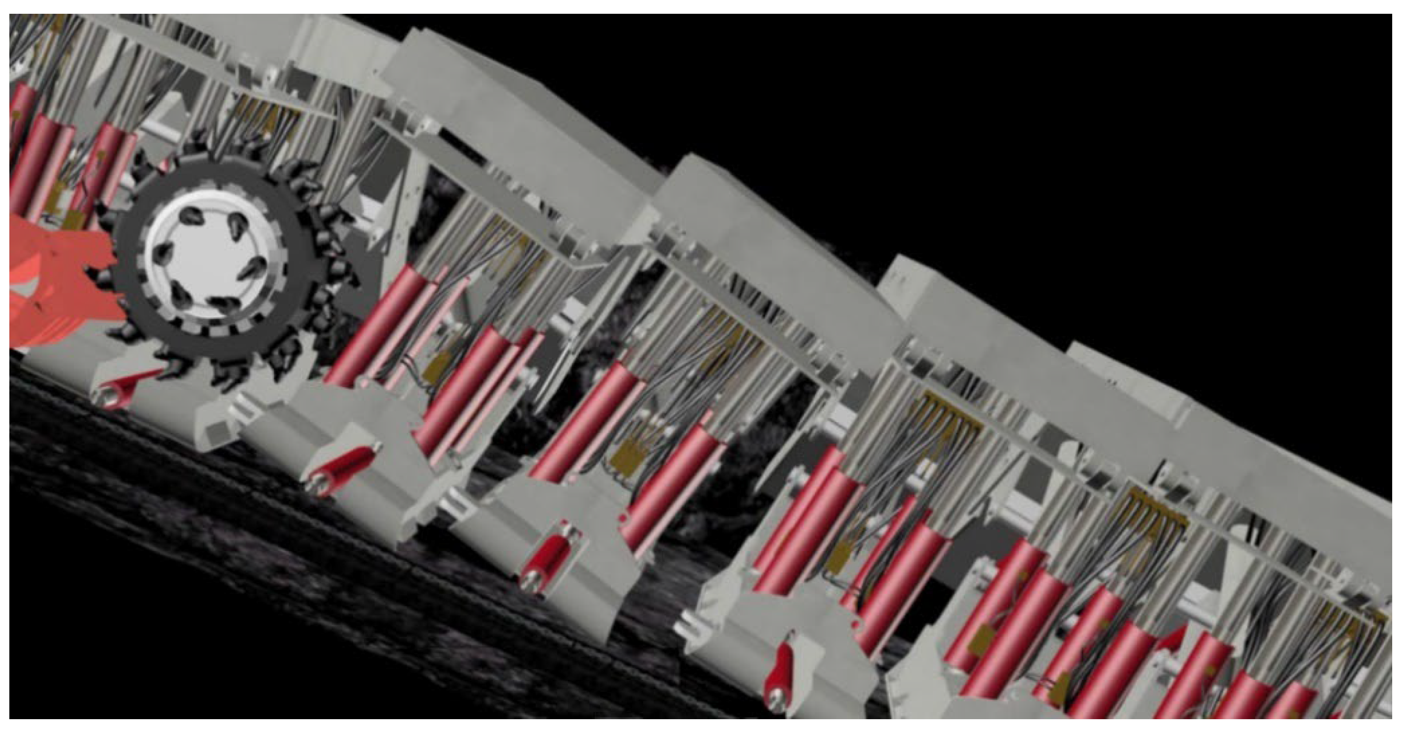
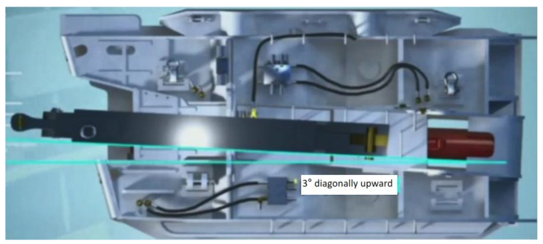
The conveyor pushing rod is guided through the whole process, the gap between the push rod and the base is controlled in 10~20 mm, and the pushing device is arranged 3° diagonally upward to control the sliding rod angle (Figure 11).
(2)
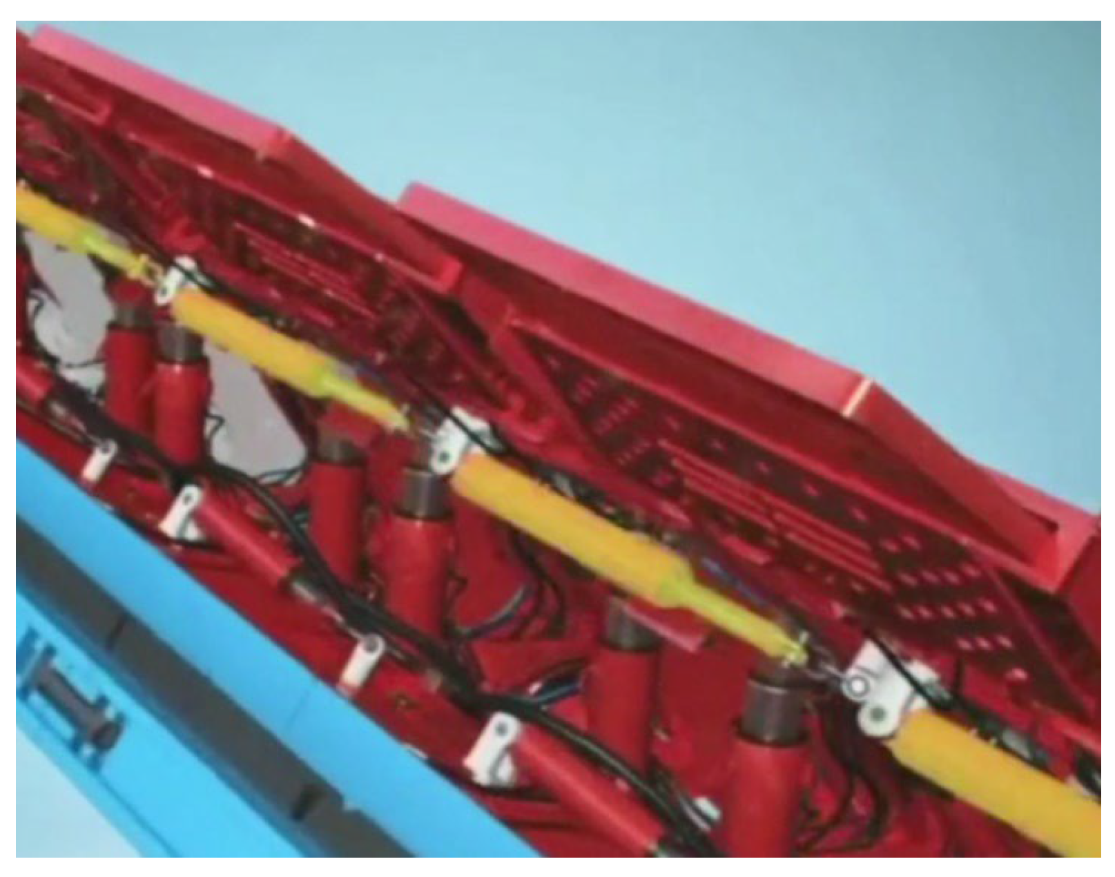
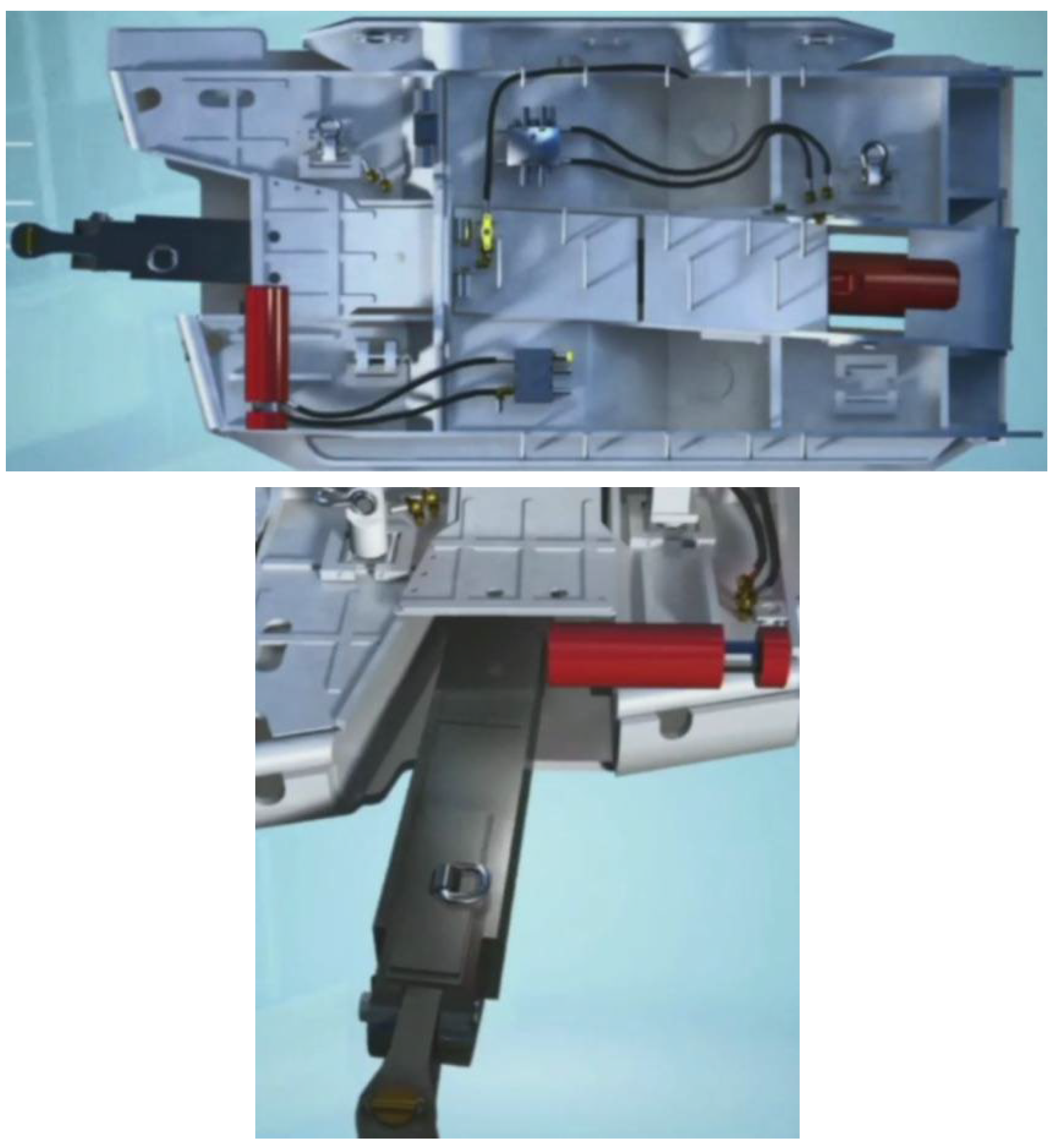
Add the pushing rod limiting jack to limit the swing angle of the push rod (Figure 12).
(3)
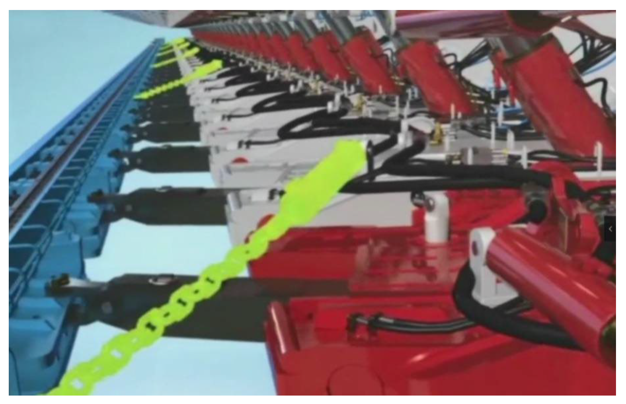
Anti-slip jacks are set between adjacent support bases, the support with initial support force is used as the fulcrum, the position of the adjacent support is adjusted, and the cable stayed oil cylinder is installed and connected with the guide connecting device (Figure 13).
(4)
The support moves from the bottom to the top along the working face starting from the second support, then moving the first support and the third frame, and on and on all the way the top.

7. Discussion

The positive aspect of the study is that some insights and practical techniques are proposed based on theoretical analysis and filed operation experience. The negative aspect of the study is that the field conditions are variable and some measures must be adjusted from time to time, which poses pressure for miners and the management section of the mine. The results and experiences can be adopted by mines with similar geologic conditions.
It may help to leave rock underground after coal mining at a working face with a large dip angle [43,44]. Such actions definitely make an influence on mining. Future studies could explore the development and implementation of more advanced intelligent support systems for coal mining operations. This could involve integrating emerging technologies such as artificial intelligence, machine learning, and sensor networks to improve the stability, safety, and efficiency of support systems in various geological conditions. In addition, researchers could investigate and refine the technical measures proposed in the current study to optimize their effectiveness in ensuring the stability of support systems. This could involve conducting additional theoretical modeling analyses, laboratory experiments, and field trials to identify the most suitable measures for different types of inclined and steeply inclined coal seams [45,46].

8. Conclusions

(1)
On the basis of considering the influence of coal seam strike angles on the inclined stability of support and inclined angles on the inclined stability of support, a mechanical model of “support-surrounding rock” is established. Through the mechanical calculation and analysis of the free state and working state of the working face support, it is concluded that the critical tipping angle of the support in the free state is 27.8°, and the critical slip angle is 16°. The support is more prone to slip in the free state.
(2)
Failure slip will occur on the floor. When the trend and rate of roof collapse are different from the trend and rate of failure slip on the floor, it will cause the instability of the “floor-support-roof” system on the working face, resulting in disastrous accidents.
(3)
With the increase in tangential component force and the decrease in normal component force, the working load received by the supporting system of the working face becomes smaller, the external load causing the instability of the supporting system increases, and it is easy for the support slip, fall, and tilt.
(4)
A series of shield stability control anti-fall and anti-slip technologies of intelligent working face supports with a large dip angle is conducive to ensuring the stability of mine support and improving safety.

Author Contributions

Methodology, B.S.; Investigation, P.W.; Writing—original draft, P.W. All authors have read and agreed to the published version of the manuscript.

Funding

This research was funded by [National Natural Science Foundation of China] grant number [52274092].

Data Availability Statement

Data is available from the authors upon reasonable request.

Conflicts of Interest

The authors declare no conflict of interest.

References

  1. Kulakov, V.N. Stress state in the face region of a steep coal bed. J. Min. Sci. 1995, 31, 02047661. [Google Scholar] [CrossRef]
  2. Hahn, H.; Hintze, W.; Treumann, H. Safety and Technological Aspects of Black Powder. Propellants Explos. Pyrotech. 1980, 5, 129–134. [Google Scholar] [CrossRef]
  3. Singh, T.N.; Gehi, L.D. State behavior during mining of steeply dipping thick seams—A case study. In Proceedings of the 27th International Symposium on Thick Seam Mining, Dhanbad, India, 19–21 November 1992; pp. 311–315. [Google Scholar]
  4. Feng, G.; Wang, P.; Zhao, J.; Wang, Z. A Coal Burst Mitigation Strategy for Gateroad in Mining of Deep Inclined Longwall Panels at Huafeng Coal Mine. Shock. Vib. 2018, 2018, 5929785. [Google Scholar]
  5. Zhao, J.; Wang, P.; Su, Y. An Innovative Longwall Mining Technology in Tangshan Coal Mine, China. Minerals 2017, 7, 14. [Google Scholar] [CrossRef] [Green Version]
  6. Feng, G.; Wang, P.; Chugh, Y.P. A New Gob-Side Entry Layout for Longwall Top Coal Caving. Energies 2018, 11, 1292. [Google Scholar] [CrossRef] [Green Version]
  7. Alejano, L.R.; Ramírez-Oyanguren, P.; Taboada, J. FDM predictive methodology for subsidence due to flat and inclined coal seam mining. Int. J. Rock Mech. Min. Sci. 1999, 36, 475–491. [Google Scholar] [CrossRef]
  8. Feng-hai, M.A.; Li, S.; Dun, L.I. Numerical simulation analysis of covering rock strata as mining steep-inclined coal seam under fault movement. Trans. Nonferrous Met. Soc. China 2011, 21, s556–s561. [Google Scholar]
  9. Ching, J.; Yang, Z.; Shiau, J.; Chen, J. Estimation of rock pressure during an excavation/cut in sedimentary rocks with inclined bedding planes. Struct. Saf. 2013, 41, 11–19. [Google Scholar] [CrossRef]
  10. Xin, Y.; Gou, P.; Ge, F. Analysis of stability of support and surrounding rock in mining top coal of inclined coal seam. Int. J. Min. Sci. Technol. 2014, 24, 63–68. [Google Scholar] [CrossRef]
  11. Lin, Y.; Hong, Y.; Zheng, S.; Zhang, Y. Failure modes of openings in a steeply bedded rock mass. Rock Mech. Rock Eng. 1984, 17, 113–119. [Google Scholar]
  12. Gao, W. Study on the width of the non-elastic zone in inclined coal pillar for strip mining. Int. J. Rock Mech. Min. Sci. 2014, 72, 304–310. [Google Scholar]
  13. Huang, X. Physical model test and numerical analysis on the behavior of stratified rock masses during underground excavation. Int. J. Rock Mech. Min. Sci. 2012, 49, 134–147. [Google Scholar]
  14. Das, A.J.; Mandal, P.K.; Bhattacharjee, R.; Roy, L.B. Evaluation of stability of underground workings for exploitation of an inclined coal seam by the ubiquitous joint model. Int. J. Rock Mech. Min. Sci. 2017, 93, 101–114. [Google Scholar] [CrossRef]
  15. Das, A.J.; Mandal, P.K.; Paul, P.S.; Sinha, R.K. Generalised Analytical Models for the Strength of the Inclined as well as the Flat Coal Pillars using Rock Mass Failure Criterion. Rock Mech. Rock Eng. 2019, 52, 3921–3946. [Google Scholar] [CrossRef]
  16. Das, A.J.; Mandal, P.K.; Paul, P.S.; Sinha, R.K.; Tewari, S. Assessment of the Strength of Inclined Coal Pillars through Numerical Modelling based on the Ubiquitous Joint Model. Rock Mech. Rock Eng. 2019, 52, 3691–3717. [Google Scholar] [CrossRef]
  17. Foroughi, M.H. Some Aspects of Coal Pillar Stability in Inclined Coal Seams. Ph.D. Thesis, University of New South Wales, Sydney, NSW, Australia; p. 273.
  18. Jessu, K.V.; Spearing, A.J.S. Performance of inclined pillars with a major discontinuity. Int. J. Min. Sci. Technol. 2019, 29, 437–443. [Google Scholar] [CrossRef]
  19. Jessu, K.V.; Spearing, A.J.; Sharifzadeh, M. Mostafa Sharifzadeh. Laboratory and Numerical Investigation on Strength Performance of Inclined Pillars. Energies 2018, 11, 3229. [Google Scholar] [CrossRef] [Green Version]
  20. Sun, J.; Wang, L.G.; Tang, F.R. Micro-seismic monitoring failure characteristics of inclined coal seam floor. Rock Soil. Mech. 2011, 32, 1589–1594. [Google Scholar]
  21. Wang, Z.; Dou, L.; Wang, G. Coal Burst Induced by Horizontal Section Mining of a Steeply Inclined, Extra-Thick Coal Seam and Its Prevention: A Case Study from Yaojie No. 3 Coal Mine, China. Shock. Vib. 2019, 2019, 8469019. [Google Scholar] [CrossRef]
  22. Çelik, A.; Özçelik, Y. Investigation of the effect of caving height on the efficiency of the longwall top coal caving production method applied in inclined and thick coal seams by physical modeling. Int. J. Rock Mech. Min. Sci. 2023, 162, 105304. [Google Scholar] [CrossRef]
  23. Çelik, A. Investigation of Longwall Caving Method Efficiency in Inclined Thick Coal Seams by Physical Modelling. Ph.D. Thesis, The Graduate School of Science and Engineering, Hacettepe University, Ankara, Turkey, 2022. [Google Scholar]
  24. Çelik, A.; Özçelik, Y. Investigation of the effects of coal seam slope and top coal drawn height on top coal recovery ratio in longwall top coal caving method applied in steep inclined thick coal seams. Arab. J. Geosci. 2022, 15, 181. [Google Scholar] [CrossRef]
  25. Tu, H.; Tu, S.; Yuan, Y.; Bai, Q. Present situation of fully mechanized mining technology for steeply inclined coal seams in China. Arab. J. Geosci. 2015, 8, 4485–4494. [Google Scholar] [CrossRef]
  26. Klishin, S.V.; Klishin, V.I.; Opruk, G.Y. Modeling coal discharge in mechanized steep and thick coal mining. J. Min. Sci. 2013, 49, 932–940. [Google Scholar] [CrossRef]
  27. Kostyuk, S.; Bedarev, N.; Lyubimov, O.; Kovalyov, N. Searching for the Optimal Parameters of the Thick Steep Seams‘ Under-Level Development. E3S Web Conf. 2018, 41, 01002. [Google Scholar] [CrossRef] [Green Version]
  28. Klishin, V.I.; Klishin, S.V. Coal Extraction From Thick Flat And Steep Beds. J. Min. Sci. 2010, 46, 149–159. [Google Scholar] [CrossRef]
  29. Selyukov, A.; Gerasimov, A.; Grishin, V. The Results of Mining and Geometric Analysis in Open Pit Mining of Promising Kuzbass Coal Deposits with Block System. E3S Web Conf. 2020, 174, 01020. [Google Scholar] [CrossRef]
  30. Rak, Z. Mechanised sublevel caving systems for winning thick and steep hard coal beds. In International Mining Forum 2010: Mine Safety and Efficient Exploitation Facing Challenges of the 21 Century; CRC Press: Boca Raton, FL, USA, 2010; pp. 361–370. [Google Scholar]
  31. Kolesnikov, V.; Katsubin, A.; Martyanov, V.; Dobrov, A. Features of the Excavation and Loading Equipment of Various Types in the Development of Inclined and Steep Beds. E3S Web Conf. 2019, 105, 01023. [Google Scholar] [CrossRef] [Green Version]
  32. Jawed, M.; Sinha, R.K. Design of rhombus coal pillars and support for roadway stability and mechanizing loading of face coal using SDLs in a steeply inclined thin coal seam—A technical feasibility study. Arab. J. Geosci. 2018, 11, 415. [Google Scholar] [CrossRef]
  33. Kumar, R.; Mandal, P.K.; Ghosh, N.; Das, A.J.; Banerjee, G. Design of stable parallelepiped coal pillars considering geotechnical uncertainties. Rock Mech. Rock Eng. 2023. [Google Scholar] [CrossRef]
  34. Duc, T.P.; Tuan, A.P.; Vitcalov, V.; Le Quang, P. Justification of spatially-planned solutions and determination of the dimension block in the working of the medium thick inclined coal seams with the room and pillar system. E3S Web Conf. 2018, 41, 01024. [Google Scholar]
  35. Zhao, P.; Zhuo, R.; Li, S.; Shu, C.M.; Jia, Y.; Lin, H.; Chang, Z.; Ho, C.; Bin, L.; Xiao, P. Fractal characteristics of methane migration channels in inclined coal seams. Energy 2021, 225, 120127. [Google Scholar] [CrossRef]
  36. Nikitenko, M.S.; Malakhov, Y.V.; Neogi, B.; Chakraborty, P.; Banerjee, D. Robotic complex for the development of thick steeply-inclined coal seams and ore deposits. IOP Conf. Ser. Earth Environ. Sci. 2017, 84, 012002. [Google Scholar] [CrossRef]
  37. Asadi, A.; Shahriar, K.; Goshtasbi, K.; Najm, K. Development of a new mathematical model for prediction of surface subsidence due to inclined coal-seam mining. J. S. Afr. Inst. Min. Metall. 2005, 105, 15–20. [Google Scholar]
  38. Erdem, B.; Duran, Z. A model for extended bench casting in dipping coal seam. J. Sci. Ind. Res. 2007, 66, 435–443. [Google Scholar]
  39. Eremin, M.; Peryshkin, A.; Esterhuizen, G.; Pavlova, L.; Fryanov, V. Numerical analysis of pillar stability in longwall mining of two adjacent panels of an inclined coal seam. Appl. Sci. 2022, 12, 11028. [Google Scholar] [CrossRef]
  40. Dudek, M.; Tajduś, K. FEM for prediction of surface deformations induced by flooding of steeply inclined mining seams. Geomech. Energy Environ. 2021, 28, 100254. [Google Scholar] [CrossRef]
  41. Vu, T.T. Solutions to prevent face spall and roof falling in fully mechanized longwall at underground mines, Vietnam. Min. Miner. Depos. 2022, 16, 127–134. [Google Scholar] [CrossRef]
  42. Shavarskyi, I.; Falshtynskyi, V.; Dychkovskyi, R.; Akimov, O.; Sala, D.; Buketov, V. Management of the longwall face advance on the stress-strain state of rock mass. Min. Miner. Depos. 2022, 16, 78–85. [Google Scholar] [CrossRef]
  43. Smoliński, A.; Malashkevych, D.; Petlovanyi, M.; Rysbekov, K.; Lozynskyi, V.; Sai, K. Research into Impact of Leaving Waste Rocks in the Mined-Out Space on the Geomechanical State of the Rock Mass Surrounding the Longwall Face. Energies 2022, 15, 9522. [Google Scholar] [CrossRef]
  44. Malashkevych, D.; Petlovanyi, M.; Sai, K.; Zubko, S. Research into the coal quality with a new selective mining technology of the waste rock accumulation in the mined-out area. Min. Miner. Depos. 2022, 16, 103–114. [Google Scholar] [CrossRef]
  45. Satsuk, T.P.; Sharyakov, V.A.; Sharyakova, O.L.; Kovalev, D.A.; Vorob’ev, A.A.; Makarova, E.I. Automatic Voltage Stabilization of an Electric Rolling Stock Catenary System. Russ. Electr. Engin. 2021, 92, 349. [Google Scholar] [CrossRef]
  46. Martirosyan, A.V.; Ilyushin, Y.V. The Development of the Toxic and Flammable Gases Concentration Monitoring System for Coalmines. Energies 2022, 15, 8917. [Google Scholar] [CrossRef]
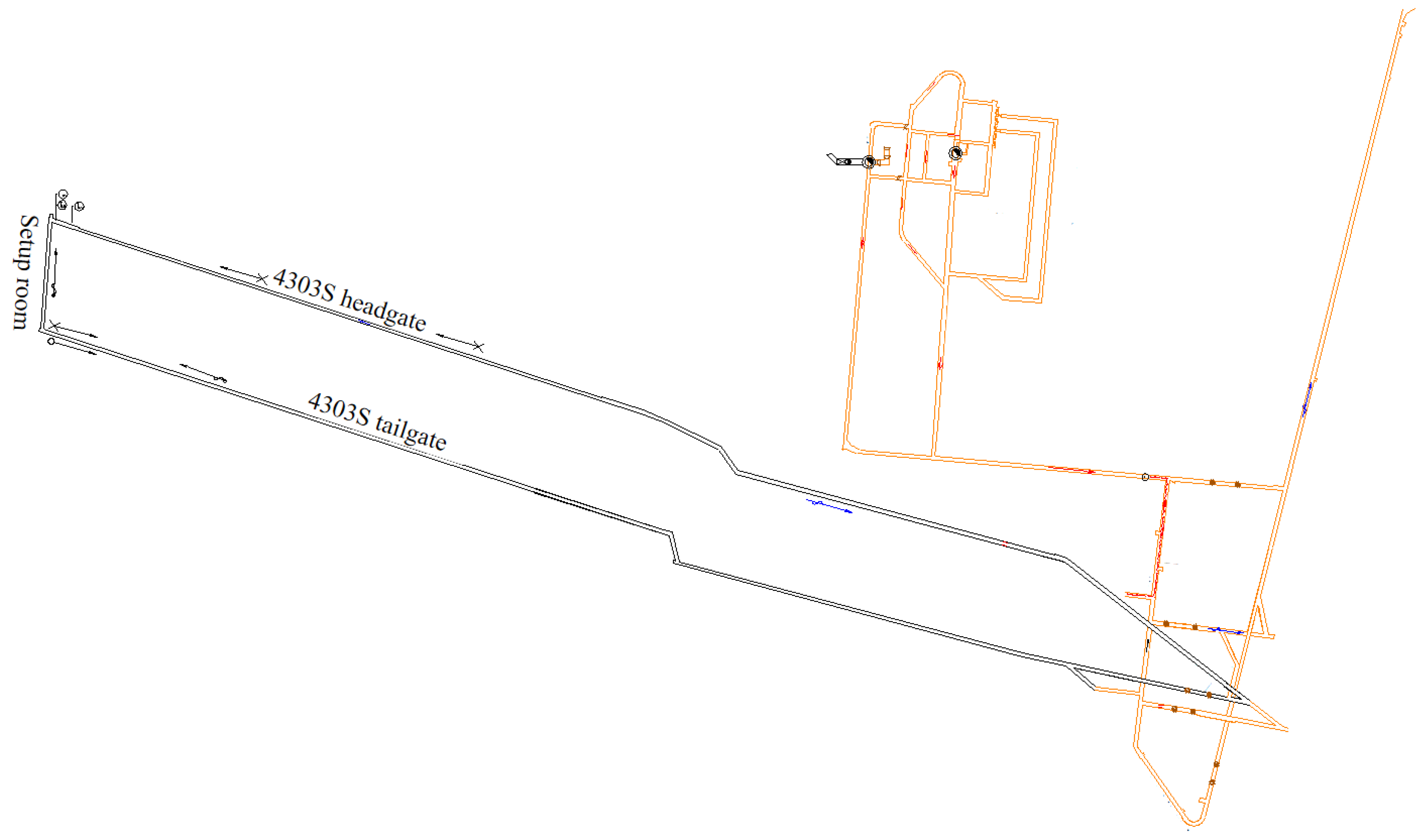
Figure 1. Layout of the panel.
Energies 16 05813 g001
Figure 2. The force distribution of support affected by dead weight.
Energies 16 05813 g002
Figure 3. Mechanical model of support along the dip; (a) Support tipping model, (b) Support slip model.
Energies 16 05813 g003
Figure 4. Mechanical model of support along dip under working condition; (a) Support tipping model, (b) Support slip model.
Energies 16 05813 g004
Figure 5. Stress tendency of the support in case of a serious roof collapse (Arrows means load of the overburden).
Energies 16 05813 g005
Figure 6. Mechanical model of support along dip in special period; (a) Support tipping model in special period, (b) Support slip model in special period.
Energies 16 05813 g006
Figure 7. Monitored shields.
Energies 16 05813 g007
Figure 8. Large dip angle face support tipping.
Energies 16 05813 g008
Figure 9. Adjusting jack between the adjacent supports.
Energies 16 05813 g009
Figure 10. Base adjusting jack.
Energies 16 05813 g010
Figure 11. Arrangement of conveyor pushing rod on the support.
Energies 16 05813 g011
Figure 12. Pushing rod limiting jack.
Energies 16 05813 g012
Figure 13. Cable-stayed oil cylinder.
Energies 16 05813 g013
Table 1. Position of 4303S panel.
Level Name+750 m levelName of Mining DistrictFourth mining district
Elevation on the surface1238.1~1244.2 mElevation underground993.8~759.2 m
Position of the panelOn the northeast of the surface industrial sites.
The influence of mining on the surface facilitiesThe corresponding ground position of the working face is a semi-fixed dune without buildings, and the working face has no influence on the ground buildings during the mining period.
LocationTo the east of the panel is the 4304S panel, and to the west is the coal pillar protected by the zone of oxidized zone. To the south is the protective coal pillar of the ancient Great Wall, and to the north is the setup room of the 4303 (W) panel
Table 2. Coal seam condition.
Seam No.3 UpperThickness of Coal Seam (m)1.8~2.4Inclination (°)33~42
2.137.5
Texture of coal seamcomplexHardnesssoftCoal typesGas coal
Recoverable index (%)0.98Variable coefficient (%)25.98Degree of stabilityStabilization
Table 3. Hydraulic support main technical characteristics.
Type No.ZFS5000/17/34Accommodated
Dip Angle
≥20°
Working resistance4650 kNOpening width1700~3400 mm
Center to center spacing1500 mmMoving distance for each step600 mm
Pump station pressure31.5 MPaMode of operationLocal operation
Type No.ZFG5600/18/33Adaptation to seam dip≥20°
Working resistance5600 kNSupport height1800~3300 mm
Center distance of support1500 mmMoving distance for each step600 mm
Pump station pressure31.5 MpaMode of operationLocal operation
Table 4. The inclined critical tipping angle of different cutting heights and inclined (upward) mining angles under the free state of the support.
Cutting Height (m)
Angle of Mining Downdip (updip) (°) 2.8 3 3.2
527.826.124.7
1026.524.823.2
1524.222.220.4
2020.317.915.5
2513.59.32.6
Table 5. The inclined critical slip angle under the free state of the support at different angles of mining downdip (updip).
Angles of mining downdip (updip)/(°)510152025
Support inclined critical slip/(°)16.013.57.4SlippageSlippage
Table 6. Periodic weighting data of 1# station.
ItemsTimeTime Interval/
Day
Stress
/MPa
Periodic Weighting Interval/m
No.
8#April 21621~2718
April 26515
April 31515
9#April 23522~2615
April 29618
May 3515
10#April 26526~3015
April 30412
Table 7. Periodic weighting data of 2# station.
ItemsTimeTime Interval
/Day
Stress
/MPa
Periodic Weighting Interval/m
No.
45#May 17523~2915
May 23618
May 27412
46#May 19726~2921
May 25618
May 30515
47#May 21627~3118
May 2439
Table 8. Periodic weighting data of 3# station.
ItemsTimeTime Interval
/Day
Stress
/MPa
Periodic Weighting Interval/m
No.
95#May 19519~2415
May 23412
May 27412
96#May 22521~2315
May 26412
May 31515
97#May 24323~269
May 28412
Disclaimer/Publisher’s Note: The statements, opinions and data contained in all publications are solely those of the individual author(s) and contributor(s) and not of MDPI and/or the editor(s). MDPI and/or the editor(s) disclaim responsibility for any injury to people or property resulting from any ideas, methods, instructions or products referred to in the content.