Review

Electrification of Offshore Oil and Gas Production: Architectures and Power Conversion

by
Anindya Ray
and
Kaushik Rajashekara
*,†
Department of Electrical and Computer Engineering, University of Houston, Houston, TX 77204, USA
*
Author to whom correspondence should be addressed.
These authors contributed equally to this work.
Energies 2023, 16(15), 5812; https://doi.org/10.3390/en16155812
Submission received: 27 June 2023 / Revised: 21 July 2023 / Accepted: 2 August 2023 / Published: 4 August 2023
(This article belongs to the Topic Advanced Engines Technologies)

Abstract

:
Subsea oil and gas (O&G) exploration demands significantly high power to supply the electrical loads for extraction and pumping of the oil and gas. The energy demand is usually met by fossil fuel combustion-based platform generation, which releases a substantial volume of greenhouse gases including carbon dioxide (CO2) and methane into the atmosphere. The severity of the resulting adverse environmental impact has increased the focus on more sustainable and environment-friendly power processing for deepwater O&G production. The most feasible way toward sustainable power processing lies in the complete electrification of subsea systems. This paper aims to dive deep into the technology trends that enable an all-electric subsea grid and the real-world challenges that hinder the proliferation of these technologies. Two main enabling technologies are the transmission of electrical power from the onshore electrical grid to the subsea petroleum installations or the integration of offshore renewable energy sources to form a microgrid to power the platform-based and subsea loads. This paper reviews the feasible power generation sources for interconnection with subsea oil installations. Next, this interconnection’s possible power transmission and distribution architectures are presented, including auxiliary power processing systems like subsea electric heating. As the electrical fault is one of the major challenges for DC systems, the fault protection topologies for the subsea HVDC architectures are also reviewed. A brief discussion and comparison of the reviewed technologies are presented. Finally, the critical findings are summarized in the conclusion section.

1. Introduction

The growing trend of energy demand has increased the drilling and exploration of remote offshore oil and gas (O&G) fields. Globally, nearly 1500 oil and gas rigs are located offshore, the largest share of which are in the North Sea and the Gulf of Mexico. Offshore oil and gas deposits are typically much larger than those found on the land. Offshore deep-water O&G production systems need to incorporate high-capacity electric submersible pumps and compressor motors at the seabed, which demand considerable electrical power. Power requirements can be of the order of several hundreds of MW depending on the number of subsea loads. The recent trend in the O&G industry is to install subsea processing loads on the seabed to reduce the required space on the platform or even remove the platform. There are several advantages to installing power converters and equipment close to the loads. When the electrical converters and distribution systems are placed on the seabed, it considerably reduces the power supply cost with similar reliability.
The installation and operation of subsea electrical systems on the seabed have various challenges [1]. The pressure increases by 10 bars (about 145 PSI) for every 100 m depth in the ocean. If all the systems including power electronics and motors need to be located at a water depth of about 3000 m, they have to withstand 300 bars of pressure. Hence, all electrical systems have to be designed and qualified to withstand high pressure. As seawater acts like a conductor and is corrosive, proper isolation between the electrical equipment and seawater must be provided. Also, as the equipment is located at depths of about 3000 m, post-fault maintenance and repair will be challenging and will not be possible without bringing the equipment to the surface. However, relocation of the equipment to the surface is expensive and results in long production outages. The technology for locating all the electrical equipment including the power electronics is still in the early stages of development by organizations like SINTEF in Norway. Hence, only the subsea pumps, gas compression, boosting, and water injection are generally located on the sea floor, and the power is supplied from a topside platform, including that for the downhole electric submersible pump (ESP) [2].
Presently, the required electrical power for the platform-based and subsea loads is generated on an offshore platform using either diesel engine-driven generators or gas turbines. The diesel engine-based systems emit not only greenhouse gases into the atmosphere, but also other air pollutants, such as sulfur dioxide (SOx), nitrogen oxides (NOx), and airborne particles such as soot, etc. A typical diesel generator emits 0.79 metric tons of CO2 for 1 MWh of energy produced, which is 2.15 times more than the US grid. One diesel generator of 1100 kVA will emit around 318 tons of CO2 per year (in fuel emissions and cleaning) [3].
Gas combustion-based generation is preferred due to its natural abundance in a hydrocarbon field. However, such power generation strategies have also led to a significant increase in greenhouse gas emissions. A gas turbine requires the combustion of fuel oil or natural gas to drive the electrical generators and, as a result, emits a substantial amount of CO2 into the atmosphere. Also, the gas turbines used in offshore platforms exhibit low energy conversion efficiency of about 25% to 30%, which implies the release of a significant amount of CO2 into the atmosphere. A platform with a generating capacity of 100 MW would typically release over 500,000 tons of CO2 per year, combined with the emission of about 300 tons of nitrogen oxide (NOx) [3].
According to the United States Environmental Protection Agency, offshore oil and gas production was responsible for nearly 8 million metric tons of combustion gases in 2019. The sources of emissions for offshore oil and gas production in Norway are shown in Figure 1 [4]. The greenhouse gas emissions from petroleum activities in Norway are about 14 million tons of CO2 equivalent, most of which is CO2, and the rest is methane. Offshore processing of oil and gas in the UK was 18.9 megatons of CO2 in 2018 and 17.1 m tons in 2020 (reduced due to COVID) [5].
In addition to the emissions, the electric distribution system of O&G platforms is characterized as a weak electric grid, resulting in poor power quality, a lower power factor, voltage and current harmonics, voltage notches, and common-mode EMI. All these factors result in increased losses and also affect the lifetime and long-term reliability. Hence, providing enough energy to power subsea systems for oil and gas extraction presents a unique challenge due to the location of the offshore platforms and the subsea loads.
State-of-the-art offshore oil production has to comply with stringent environmental regulations by reducing greenhouse gas emissions. Reductions in CO2 emissions also decrease the operating cost, as carbon emission is taxable in countries like Norway [6]. The most sustainable method for emission reduction from subsea O&G platform installations involves the electrical power being supplied to the subsea loads either from the onshore electrical grid or from the interconnection with offshore renewable energy sources in a microgrid architecture. Offshore wind power generation has zero carbon footprint and has the highest installed capacity among all renewable sources with minimum intermittency [7,8]. In addition to wind power, tidal and wave power concepts have also found increased focus for offshore electrification [9,10].
This paper explores the technologies that could power offshore electrical loads to reduce platform-based emissions. The methods that are discussed in this paper are: (1) efficiency improvement of the platform power generation, (2) integration of offshore renewable energy sources to power offshore loads, and (3) powering offshore loads from onshore using long-distance transmission, either HVAC or HVDC. The second and third methods help to achieve the goal of an all-electric subsea system that enables more energy-efficient production and lower greenhouse gas emissions. Moreover, simple engineering adjustments such as combining a larger adjustable speed injection pump with a smaller fixed speed pump, using step-out cables to supply adjustable speed pumps, and using floating wind turbines to power the compressors, etc. to aid the emission reduction goal have also been explored [11]. The electrification of auxiliary subsea functions such as subsea pipeline heating to melt the hydrates formed inside the pipeline also helps in lowering CO2e emissions. Hence, a power conversion system for pipeline heating is also reviewed in this paper. The exploration of all these technologies points towards the trend of offshore wind-based microgrids and HVDC interconnection for future all-electric subsea systems. However, the main obstacle lies with the lifetime of the mechanical components involved, and a demand-specific reliability study is essential [12].

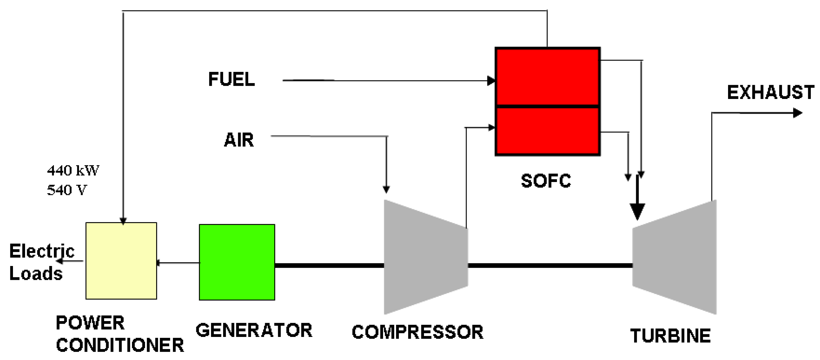
2. Efficiency Improvement of Platform Power Generation

Gas turbine-based efficiency can be improved by capturing and using the waste heat from the gas turbine using a bottoming steam Rankine cycle [13]. Power generation using this combined cycle approach can be increased by 30%, and the overall plant efficiency can be as high as 50%. However, the energy loss is still significantly large in a combined-cycle gas turbine-based system, and the processing integration can be challenging, resulting in a sub-optimal emission reduction solution. The average CO2 emissions from a natural gas-fired, combined-cycle power plant are approximately 0.46 metric tons of CO2 per MWh of electricity generated. The integration of carbon capture and storage units in subsea processing systems has been investigated, with an incremental improvement in the exergy index [14].
Emission reduction in platform power generation with the use of renewable energy sources can be achieved using hybrid fuel cell power generation systems. This could be incorporated by combining a high-temperature solid oxide fuel cell (SOFC) with the gas turbine, which would increase the overall cycle efficiency while reducing per-kilowatt emissions. The combined system has far greater efficiency than could be provided by either system operating alone. Combining higher efficiencies combined with low emissions, hybrid systems are a good choice for reducing platform-based emissions due to power generation.
A high-level architecture of a SOFC/gas turbine hybrid system is shown in Figure 2. In this hybrid power system, a compressor and heat exchanger are included with the turbine. The ambient air is compressed and supplied to the cathode of the SOFC, and the anode is supplied from the fuel, which is reformed to hydrogen. The exhaust of the SOFC, at a high temperature of about 800 °C to 1000 °C, is supplied to the turbine, which causes the desired heat and pressure difference suitable to drive the turbine. The turbine-driven generator output can be combined with the fuel cell output to supply power to subsea loads. This type of hybrid generation can achieve much higher efficiency, of the order of 65% to 70%, compared to the gas turbine or SOFC operating alone. Also, the emission per kW is reduced significantly. A hybrid fuel cell-gas turbine-based approach has also been explored for CO2 capture in platform generation [15,16]. If SOFC is used, the fuel cell can directly use the locally generated natural gas with external or internal reforming to generate power. As per the need, the same SOFC can be combined with a gas turbine to increase the overall efficiency as shown in Figure 2. However, a polymer electrolyte membrane (PEM) fuel cell can also be used if the green hydrogen is generated with excess wind power using electrolysis. The reformed hydrogen can also be used for the PEM fuel cell after further purification.

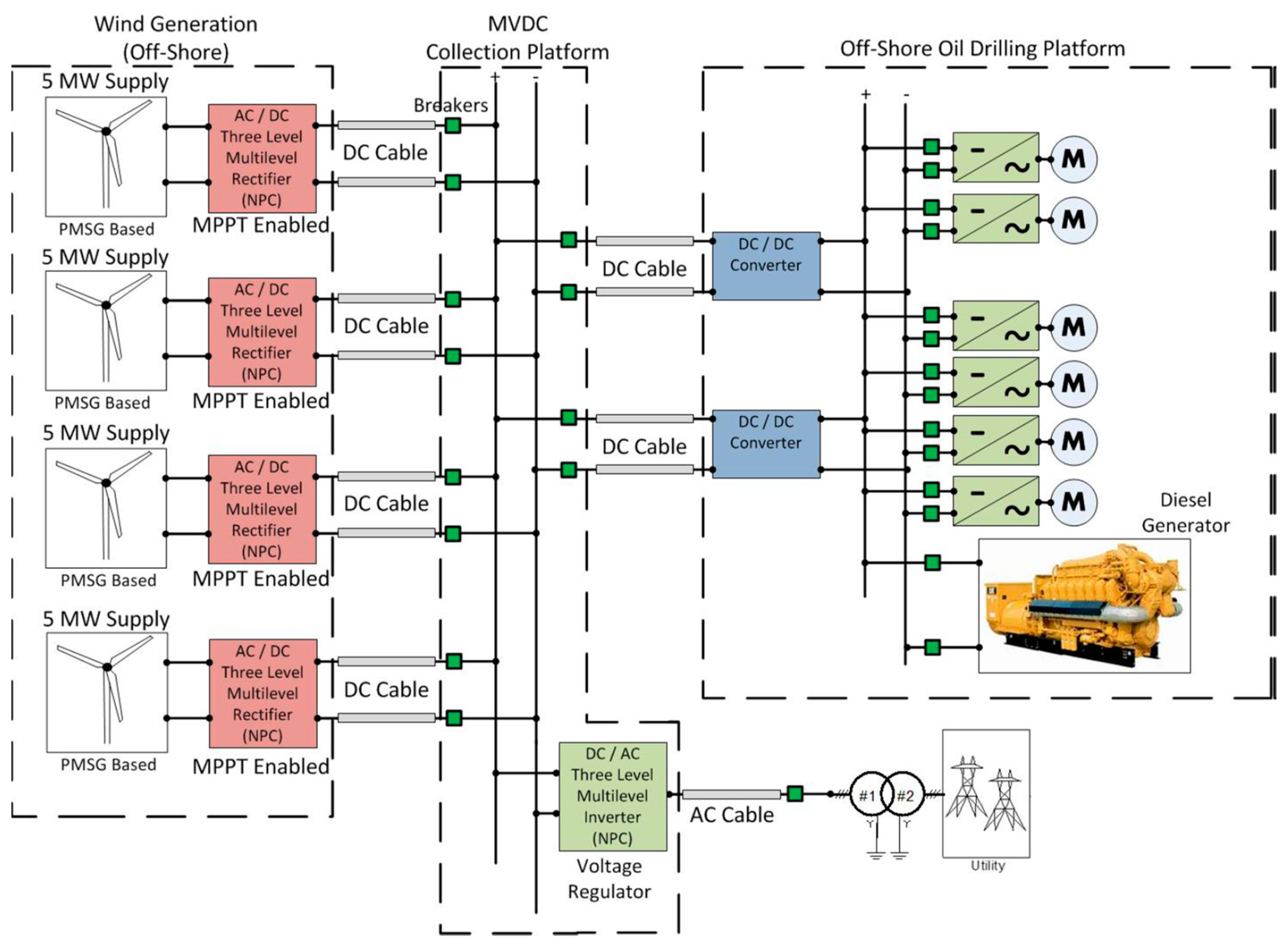
3. Integration of Offshore Renewable Energy Sources to Power Offshore Loads

Offshore energy resources can be mainly categorized as offshore wind and ocean renewable energy. Ocean renewable energy (ORE) is broadly defined as all the feasible energy sources harvested from ocean waters. The main categories of ORE are tidal energy, wave energy, and ocean thermal energy conversion (OTEC) [17]. Offshore wind power is potentially the most feasible option for subsea electrification and subsequent emission reduction. Offshore wind farms have the largest generation potential among all renewable sources. The synergy between offshore wind and offshore O&G is already underway in Europe, where multiple oil, gas, and marine companies are engaged in wind energy development [18,19]. According to the International Energy Agency (IEA), total offshore wind capacity is forecast to be more than triple by 2026, reaching close to 120 GW.
Major energy companies are looking to boost offshore wind development for electrification of offshore oil and gas platforms along with green hydrogen production. Equinor is studying possible options for building a floating 1 GW offshore wind farm in the Troll area with a predicted annual production of ~4.3 TWh by 2027. This could provide much of the electricity needed to run the Troll-A offshore fields [20]. Shell has announced a plan to start building Europe’s largest renewable hydrogen plant in the port of Rotterdam. This hydrogen will use renewable power for the electrolyzer from the offshore wind farm Hollandse Kust (noord), partly owned by Shell [21]. The 1.32 GW Hornsea 2 (UK) is the largest operating offshore wind farm in the world. It is 462 km2 (178 square miles) in size and can power more than 1.3 million homes. China’s MingYang Smart Energy has announced an offshore wind turbine even bigger than GE’s Haliade-X. The MySE 16.0-242 is a 16-megawatt, 242-m-tall (794 ft) behemoth capable of powering 20,000 homes per unit over a 25-year service life. Commercial production is slated to begin in the first half of 2024 [22].
A case study based on using offshore wind power for powering the platforms located at different places and providing surplus power to an onshore grid is presented in [7]. In this study, three scenarios were considered: (1) a 20 MW small offshore wind farm with a stand-alone electrical grid on the offshore oil and gas platform; (2) a 100 MW wind farm is connected to five nearby oil and gas platforms by subsea power cables, as shown in Figure 3; (3) a 1000 MW wind farm for supplying wind power both to oil and gas platforms and to an onshore electrical grid. Based on the simulation study, it was observed that these systems can significantly reduce CO2 emissions. Also, multiple subsea fields can be electrically interconnected as a large microgrid, which then connects to a large offshore wind farm. This technology enables better electrical stability of the offshore grid and reduces the carbon footprint of the entire system.
Although wind generation is intermittent, the off-generation period can be compensated for by the integration of other energy sources such as fuel cells [23,24], battery energy storage systems (BESS) [25,26,27,28], wave energy systems [17,29,30], tidal energy systems [31,32], and even platform-based generators. A microgrid based on offshore wind power and the platform diesel generator to power the offshore loads is shown in Figure 4 [8]. This is an interconnection of clusters of oil platforms in existing oil fields forming a microgrid. The system uses a medium-voltage DC grid for interconnecting the wind generators with the loads using an AC/DC and DC/DC power conversion system. When not enough offshore wind power is available, a local diesel generator is used to compensate for the deficient power from wind. This technology enables immediate power to rigs, as well as potentially supplying the onshore grid with excess renewable energy. However, this system still contributes to the emissions from diesel engines.
Wind energy can also be combined with fuel cell-based power generation. Excess wind energy can be used for hydrogen production and storage, to be used by fuel cells as and when required. A modular multiport converter-based offshore grid architecture for integrating renewables is presented in [25,33,34] and shown in Figure 5a. In [34], an offshore grid architecture with a capacity of 135 MW is described to power subsea loads. The grid interconnects various sources, including wind turbines and hybrid storage systems (HSSs) comprising fuel cells, lithium-ion batteries, and a HVDC grid. To facilitate this, the sources are interconnected via a modular multiport DC-DC converter, as an energy router (ER), which is based on modular Quad Active Bridges (QABs). The system has been designed in a way that allows each wind turbine to be separately connected to the ER, without the need for forming a wind farm. Similarly, the HSS units are separately connected to each QAB module shown in Figure 5b, resulting in a more flexible system with fewer maintenance requirements.
In the system in Figure 5b, the four ports of the energy router are used to integrate wind energy, backup energy storage, an on-shore DC grid, and the subsea load. The energy router provides galvanic isolation, matches the voltage level between the distributed energy sources and the load, and manages power flow from the sources to the load. Such solid-state transformer-based multiport active bridge converters are used for integrating renewable energy sources to power the subsea loads. The main advantage of these converters is that a single unit of a solid-state transformer (SST) can be used to interconnect a number of sources, enabling an increase in power density as compared to using separate converters. SSTs have the features of instantaneous voltage compensation, power outage compensation, fault isolation, bi-directional power flow, controllability, etc. SSTs can be optimally designed and integrated into the microgrid system to have the best performance both during transient and steady-state conditions.
Apart from wind generation, a significant portion of the energy requirement for subsea electrification can be obtained through ocean renewable energy (ORE) [17]. As per [31], the theoretical potential of tidal power (including tidal range and tidal currents) is 26,280 TWh/year. Wave energy and OTEC showed an even higher energy potential of 32,000 TWh/year and 44,000 TWh/year, respectively. Despite the huge potential of ocean energy, the actual energy harvesting is limited by the low technology readiness level (TRL). Ocean thermal and salinity gradient technologies have only been explored in a few demonstration projects. Contrarily, tidal energy technology is more established. Tidal generation requires a minimum operating depth of 15–40 m, which is suitable for the electrification of platforms nearer to the shore [9]. Tidal barrage plants have been in grid-connected operation both in Europe and Asia, with installed capacities of around 250 MW [31]. Tidal current harvesting has been successfully proven in several test sites to synergize with wind turbine technology [32].
Another type of ORE, wave energy, has also been identified for its potential utilization in offshore microgrids to drive subsea electrification. A wave energy conversion (WEC) system typically consists of a floating buoy mechanically coupled with an electrical generator. The wave-induced movement of the buoy is transformed into a rotational movement to drive the generator and produce electricity. Ref. [27] explores the vast potential of ORE in South America with a 25,000 km coastline, with a significant share from WEC. The first full-scale prototype of a WEC with 100 kW capacity was installed in Pecem Port, Brazil in 2011. Similar medium TRL projects have been ongoing in other South American countries like Argentina, Uruguay, Chile, etc. WEC is also proven to be useful when combined with floating wind turbines [29,30]. A floating wind–wave-combined power generation system named ‘DBSC’ is presented in [29], which shows high power generation capacity and excellent stability. As per the techno-economic analysis of a combined wind and wave generation system, the levelized cost of energy (LCOE) is reduced by 10% [30].
As the all-electric and electro-hydraulic production systems in subsea processing have momentary load demand in several kWs, the deployment of offshore energy storage systems (ESS) has gained momentum. The offshore ESS is also a key enabler of offshore renewable interconnection to mitigate the intermittency of offshore renewables. Offshore ESS also facilitates the DC collection grid for ORE, which manifests lower transmission loss and a smaller footprint [35]. As offshore ESS can be deployed close to the power generation sources, the power processing cost is reduced. However, the harsh sea environment makes the design of long-life ESS quite challenging. Nonetheless, industries have explored offshore battery systems along with fuel cells in recent years [28,36]. A multitude of ESS options such as batteries (lead-acid/Ni-Cd/Li-ion), supercapacitors, flywheels, compressed air energy storage (CAES), and hydrogen energy storage have been reviewed in [26]. It has been observed that the best demand response is provided by Li-ion batteries and CAES.
The potential of green hydrogen in offshore microgrids is also a state-of-the-art topic for research [37,38]. A techno-economic assessment of a green hydrogen-based microgrid in a remote island of Northeastern Australia is presented in [37]. The article demonstrates that the LCOE for electricity generation is reduced, along with 20,000 kg lesser CO2e emission through this microgrid. However, the proliferation of green hydrogen-based microgrids is currently limited due to environmental regulation and compliance policies.

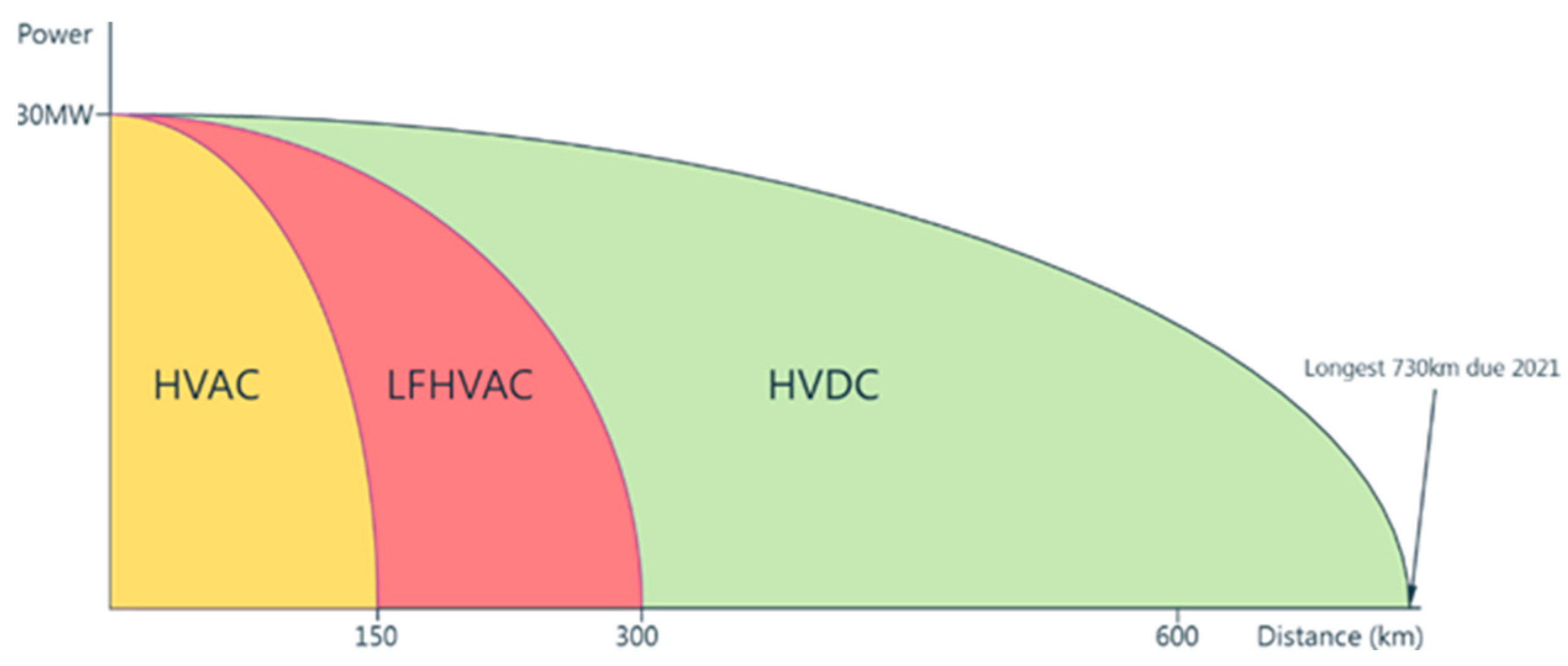
4. Powering Offshore Loads from Onshore Using Long-Distance Transmission

Platform electrification using onshore power could be the most cost-effective and efficient solution using high-voltage transmission of electric power [1,39]. One-way power transmission from an onshore grid is a highly feasible solution for subsea electrification, as variable speed drive (VSD) loads in subsea do not require regeneration. Existing high-voltage power transmission networks in offshore and subsea applications can be classified as high-voltage AC (HVAC), low-frequency AC (LFAC), and high-voltage DC (HVDC) transmission, as shown in Figure 6 [40].

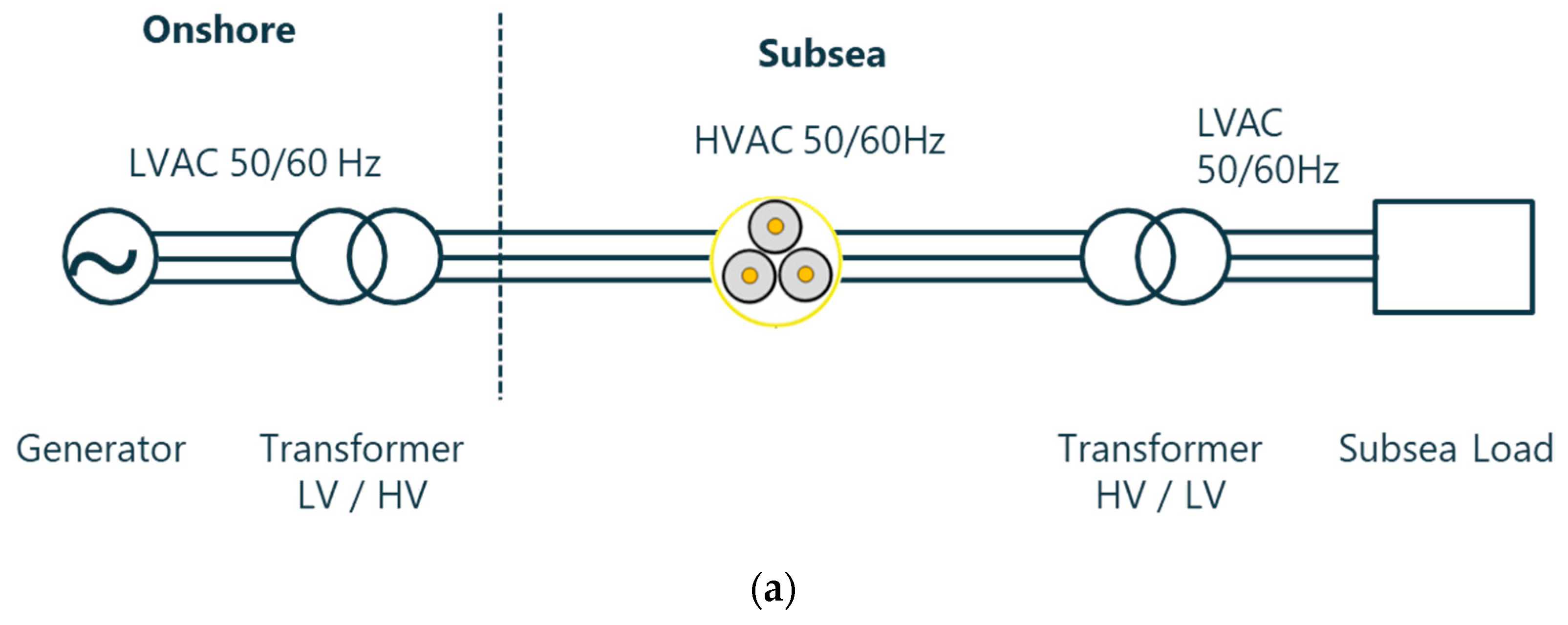
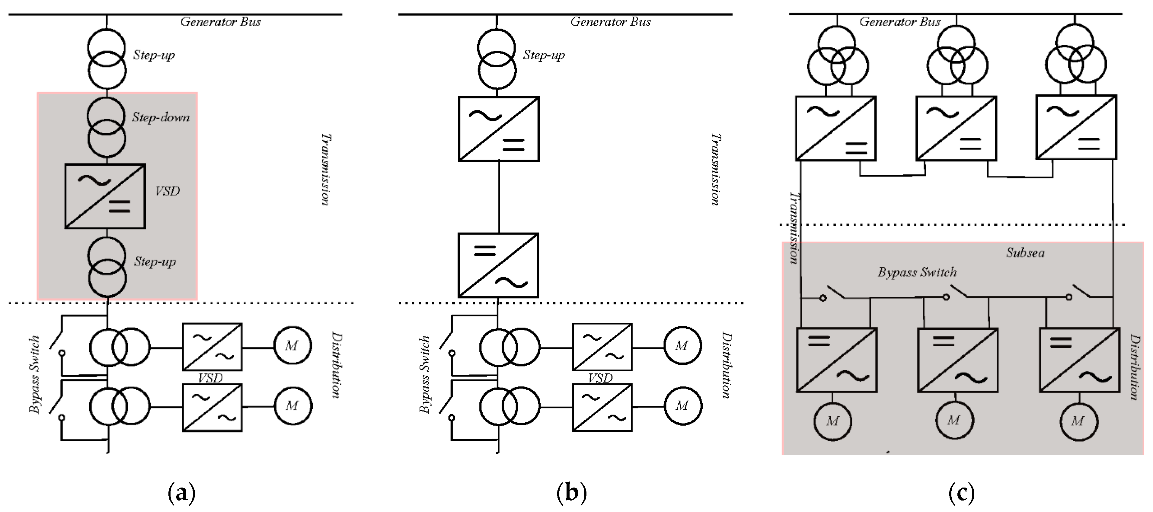
4.1. HVAC Transmission

HVAC systems are inherently simple in structure and require a lower number of power conversion stages. A typical subsea HVAC system consists of three power delivery stages. In the first stage, an onshore bus voltage is boosted by a step-up transformer to the transmission voltage level. Then, the power is transmitted to an offshore platform through the HVAC umbilical. Next, the voltage is generally stepped down and supplied to subsea loads through the power conversion system. Depending on the location of the components and the power rating, subsea HVAC architectures can be divided into three categories, as shown in Figure 7.
  • Type-I architecture: In a type-I HVAC system, the variable speed drives are located in the topside vessel or onshore. Usually, no step-down subsea transformer is deployed. Type-I systems are utilized for short transmission up to 25 km with a total load of 10–20 MVA, such as the BP King multi-booster project. In this project, the subsea loads (2 × 1 MW pumps and 2 × 2.5 MVA VSDs) are located at water depths of 1700 m and 1800 m. Two subsea cables of 24 km and 28 km in length are deployed [41].
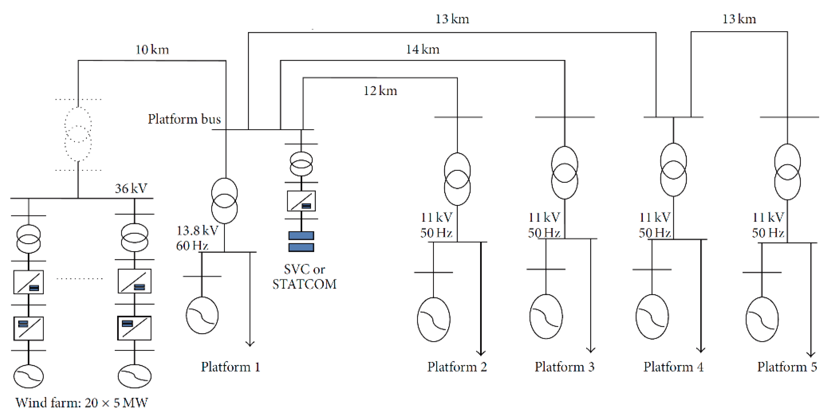
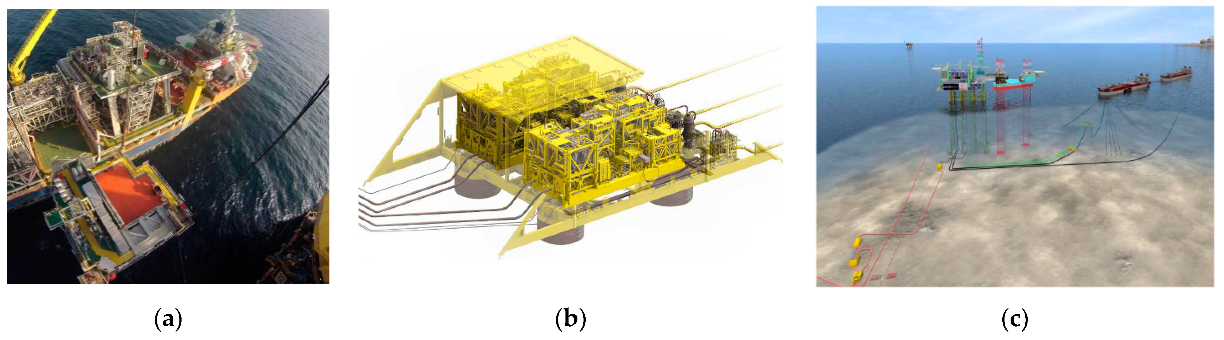
  • Type-II architecture: Type-II architecture uses a step-down subsea transformer, and the VSDs are located on the topside. This system can cater to more subsea loads and is suitable for a longer transmission distance of up to 50 km. A common example of a type-II HVAC system is the Asgard subsea compression unit. In this compression station, the power transmission to subsea motors takes place through a 40 MVA VSD topside unit and four subsea transformers, as shown in Figure 8a,b [41].
  • Type-III architecture: This architecture is widely utilized for long tie-back subsea fields such as Ormen Lange [41] and Martin Linge [36]. Usually, the transmission voltage level is 132 kV, and multiple step-down transformers may be required to supply several VSD loads. The tie-back cable length is 163 km in length for the Martin Linge field, which demands reactive power compensator installation at the topside grid.
Figure 7. Subsea HVAC architectures. (a) Type I. (b) Type II. (c) Type III [42].
Energies 16 05812 g007
Due to the standardization of high-voltage components and simplicity of operation, HVAC architectures have been popular for subsea power transmission. However, the HVAC cable has a significantly large line-to-ground capacitance, increasing with cable length. As a result, a line-charging current of substantial magnitude is drawn from the source, which results in a large reactive power demand from the source. This should be compensated for by systems such as reactive power compensators or Static Var Compensators (SVCs). The presence of a large cable capacitance in series with transformer magnetization reactance could also lead to resonance during line energizing and to possible failure. In addition, momentary voltage dips due to onshore grid disturbances amplify while propagating along long cables, leading to possible tripping of sensitive offshore equipment.

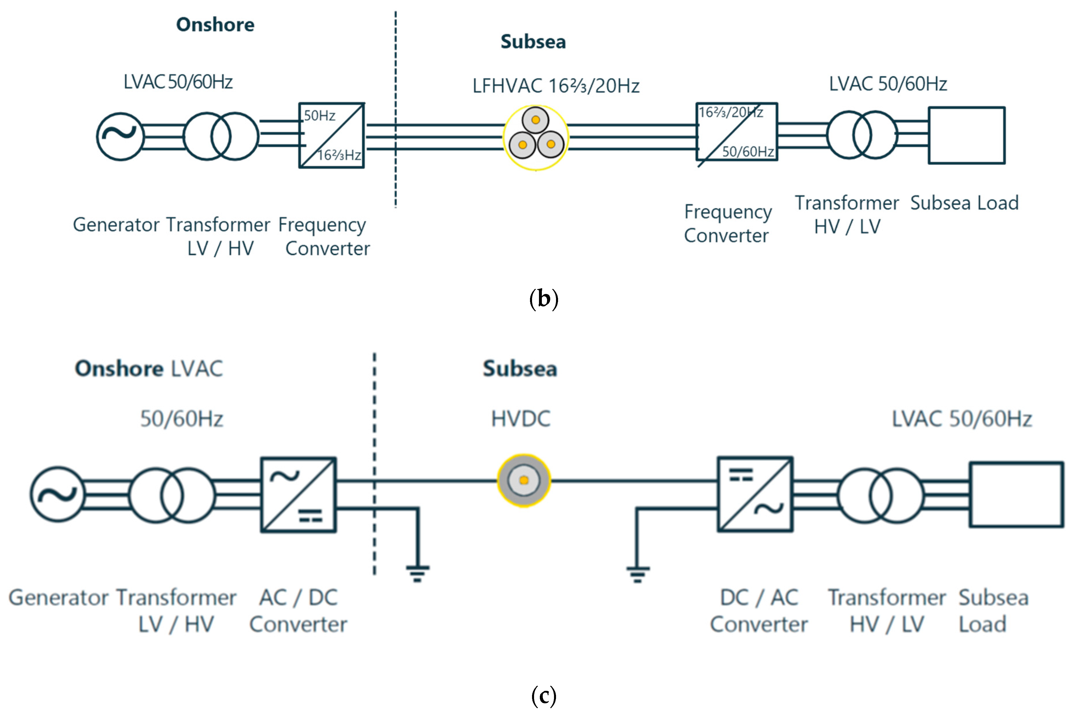
4.2. LFAC Transmission

Reactive power issues for long step-out transmission can be mitigated by low-frequency AC (LFAC) systems of 16.7 Hz or 20 Hz frequency. Also, the power transfer capability can be improved significantly by LFAC transmission [41,44,45,46]. It is quite evident that a reduction in the operating frequency leads to a decrease in the capacitive reactive power without any change in the operating voltage. This leads to the idea of the LFAC system operating at one-third of the grid frequency, i.e., 16.7 Hz or 20 Hz. LFAC systems have been employed for long-distance transmission of offshore wind power to onshore grids [45,46].
LFAC systems exhibit several advantages over the line-frequency (50/60 Hz) HVAC system in terms of increased power transfer capability, better voltage stability, and reduced charging current, which is attractive for long-tieback subsea O&G fields [42]. However, the low-frequency power transmission necessitates a frequency conversion stage, which is cascaded to a step-up/step-down transformer. Due to the large footprint of the low-frequency transformer cascaded to the frequency converter, subsea unit-based implementation of the LFAC transmission becomes challenging.

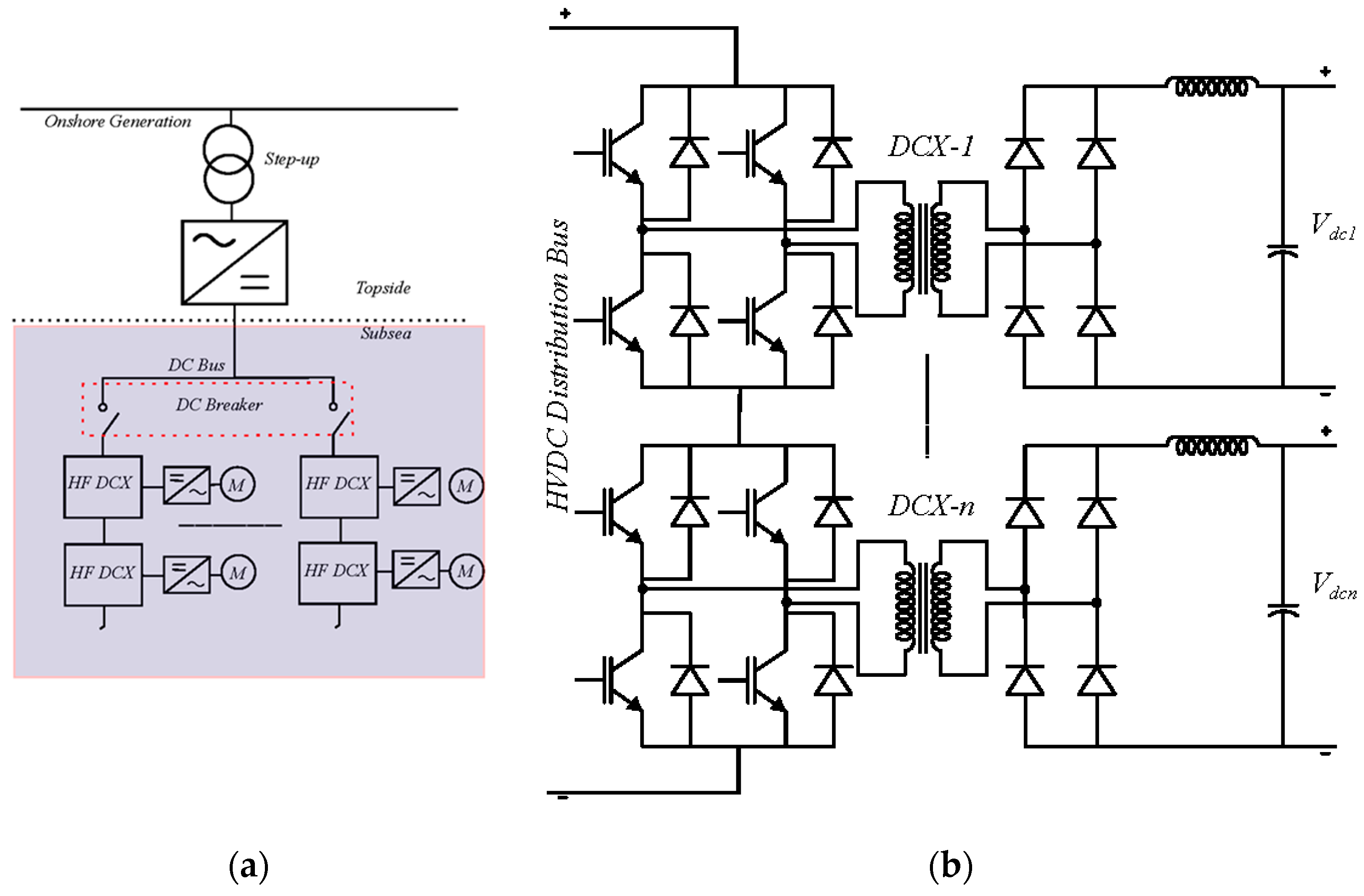
4.3. HVDC Transmission

HVDC systems demonstrate distinct advantages over HVAC in terms of higher power transfer capability, more cost-effectiveness, and no reactive power, which subsequently aids in a reduction in the carbon footprint. A simplified 132 kV transmission network of 100 km length and 100 MW power rating was considered for a comparison between HVAC and HVDC [40]. It was found that the HVDC transmission reduces the input power requirement by 5.6 MW, which translates to a reduction of 14 megatons in CO2 emission over a 20-year operating cycle.
Hence, HVDC projects are quite suitable for harnessing offshore renewable sources such as wind power [47,48,49,50,51]. Voltage-source converter (VSC)-based HVDC systems have garnered interest due to the desired performance in terms of independent control of active and reactive power, and they are designed to transmit large amounts of power over long cable distances. The growth of silicon carbide (SiC) devices has made VSC-based transmission a very attractive proposition for long tie-back offshore oil rigs. The present application of HVDC transmission in subsea O&G has been limited to a handful of projects, such as the Troll-A production platform in the North Sea [1]; HVDC transmission is utilized for a step-out distance of 70 km to drive a high-voltage ‘motorformer’ machine at 300 m water depth. However, the Troll-A configuration is not realizable for deep-water systems due to the large footprint.
To reduce the system footprint and improve reliability, ring-type architectures have been explored, which employ series-connected open-winding transformers in the distribution stage, shown in Figure 9. In case of a load-side fault, a particular section can be isolated using a bypass switch connected across the primary winding of the transformer. The transmission stage of this ring-type architecture can be either HVAC (Figure 9a) [52] or HVDC using rectifiers at the sending end (Figure 9b) [53,54,55]. Due to the point-of-load distribution system, ring-type architectures show higher redundancy and reliability than conventional hub-and-spoke-type architectures. Using a similar concept, a modular stacked DC (MSDC) transmission system, shown in Figure 9c, has been proposed by GE for long-distance subsea applications [56]. MSDC architecture employs several series-connected modular multilevel converter (MMC) modules to obtain high DC voltage.
Extending the ring distribution concept using MMCs, a novel modular HVDC architecture is proposed in [57], which is shown in Figure 10a. The offshore AC source voltage is converted to the transmission-level DC voltage through a step-up transformer and a front-end AC-DC conversion stage. The subsea HVDC cable transmits power to the subsea DC distribution bus. A cascaded structure of multiple isolated DC-DC converters shown in Figure 10b using a solid-state transformer (SST) interfaces the subsea VSD loads from the distribution bus. Voltage-mode control of each DC-DC converter provides DC voltage regulation as well as fault-tolerant operation.
Each type of transmission from onshore to platform or to direct subsea loads has its own advantages and limitations. In the HVAC system, the cable electrical losses will be higher above 100 km, in LFAC above 300 km, and HVDC is overall optimum for distances above about 150 km. Also, in HVDC systems, there no reactive power compensation is required. Figure 11 gives an idea about the distance limitations for each type of long-distance transmission to achieve the best performance [40].

4.4. Fault Protection in Subsea HVDC Systems

The main impediment in the growth of HVDC architecture for MVDC and HVDC transmission is the low TRL level of DC fault protection switchgear [58,59,60]. A short-circuit fault in a DC system results in the rapid ramp-up of the fault current. Moreover, the DC fault current does not experience any natural zero-crossing. Therefore, DC circuit breakers must interrupt such faults quickly to prevent damage to the DC system and maintain grid resiliency [61,62]. A DC circuit breaker should also operate with minimal power loss as a closed switch.
DC circuit breakers (DCCB) can be categorized as solid-state circuit breakers (SSCB) and hybrid circuit breakers (HCB). A SSCB utilizes only power semiconductor devices for fast fault interruption. A typical configuration of a SSCB is shown in Figure 12a [63,64]. During a fault, the semiconductor switch S is turned off, and the energy stored in the network inductance Ldc is dissipated in the parallel metal-oxide varistor (MOV) to clamp the switch voltage. Despite very fast fault interruption in tens of µs, the power loss and varistor sizing become a challenge for HVDC implementation.
A HCB is constructed using a mechanical circuit breaker (MCB) in parallel with switched LC networks and MOVs. The schematic of a conventional HCB is shown in Figure 12b [61,65,66,67,68]. When a fault is detected, S is turned off, and Tp is switched on at the same instant. The opening of MCB results in an arc between the moving contacts. The magnitude of arc voltage decides the current commutation to the LC branch. Tp is turned off when the MCB contacts are completely open, and the stored energy in the network inductance is dissipated by the parallel MOV branch.
HCB response and lifetime can be improved using an auxiliary LC commutation circuit to inject a current opposing the fault current. The counter-current injection forces a zero-crossing in the fault current. This results in the ZCS turn-off of the switch and isolates the faulted path. This category of circuit breakers is known as forced commutation or counter-current circuit breakers (CCCB). A typical forced commutation HCB is shown in Figure 12c, which retains the hybrid circuit breaker section of Figure 12b along with an LC circuit, where the capacitor Cc is pre-charged. Once the fault is detected, thyristor Tc is triggered; the capacitor discharges through commutation inductor Lc opposing the MCB current Im and forces the opening of MCB contacts around the current zero-crossing. Following the MCB turn-off, stored inductive energy is dissipated in the MOV. CCCB topologies using mechanical air-blast breakers or SF6 breakers have been investigated since the 1970s [69,70,71].

5. Power Processing Architectures for Direct Electric Heating

When natural gas or oil is transported in pipelines at low temperatures and high pressure, icelike crystalline hydrates may form. Hydrates create a major roadblock in O&G transport, as they clog subsea flowlines and increase pressure drops across the pipeline. In worst-case conditions, hydrates can completely stop flow through pipelines. Direct electric heating (DEH) is an inexpensive solution to preventing hydrate formation [72]. The principal objective of a DEH system is to generate heat through ohmic loss. Two distinct DEH solutions have been explored over the last two decades by the subsea industries. These are, namely, DEH for wet insulated pipelines (DEH-WIP) and DEH for pipe-in-pipe (DEH-PIP) [73,74,75].
DEH systems are single-phase AC networks with RL load. They suffer from a poor power factor due to the high inductive impedance of the pipe. Consequently, large reactive power is required for a long pipeline, leading to a high VA rating of the topside source. Additionally, balancing transformer and reactive compensation units are needed, affecting the operational cost and power density. Hence, upcoming DEH systems focus on replacing the external ac source and provide reactive compensation through power electronic solutions.
A DEH system based on single-phase modular multilevel converters (MMC) has been proposed [76]. Although a MMC is capable of handling large power, it is challenging to ensure controlled charging and voltage balancing of sub-module capacitors. Moreover, external reactive compensation is still required. An alternate solution is using resonant inverters (RI) fed from the subsea DC distribution grid. A RI can operate as a high-frequency AC source with in-built reactive compensation by the resonating elements. Multiple RIs can be interfaced from the subsea DC bus through step-down DC-DC converters for a large-scale DEH system, as shown in Figure 13 [77]. The detailed design of an LCCL RI operating in non-immittance mode is presented in [78], which shows significant advantages over the conventional DEH solution.

6. Discussions

As conventional platform-based offshore O&G power processing leads to a significant amount of CO2 emissions, the principal objective of this review paper is a deep dive into the technologies that reduce CO2 emissions and the corresponding environmental impact, while maintaining the reliability target of subsea power processing. Three main methods are explored. The first method focuses on improving efficiency and reducing emissions from the existing gas turbine-based platform power generation. The most commonly used solutions combine the gas turbine with a steam turbine or a SOFC. Although the power processing efficiency increases to around 50–70%, it is still well below the current need. The emission reduction is also not very significant. Also, this system is still a very weak grid and will manifest power quality issues.
The second method explores the integration of offshore renewable energy sources with subsea fields to power offshore loads. This method is, by far, the most promising solution to achieve the emission target, as offshore renewable energy sources like offshore wind, tidal, and WEC have almost zero carbon footprint. Also, integrating multiple energy sources with the subsea loads in microgrid formations improves the power processing efficiency, power quality, reliability, and cost KPI. However, the intermittency of renewable sources and the associated failure rates of mechanical components [12] and subsea cables cause a roadblock to the widespread use of this technology. Various solutions, such as boosting ensemble technology [79], the use of superconducting cables [80], etc., have been explored in the literature to mitigate these challenges.
The third method talks about powering the offshore loads from onshore power grids through long-distance transmission. The intermittency issue of the second method is resolved with this technology. However, HVAC transmission is not feasible for log tie-back and remote O&G fields due to reactive power demand. HVDC transmission proves to be a better option with respect to cost and transmission losses. However, the low TRL of DC fault protection limits the current HVDC proliferation. Nevertheless, many innovative technologies are being pursued to improve HVDC fault protection. Table 1 summarizes a comparison of these three methods.

7. Conclusions

This paper evaluates and reviews several electrical power generation and transmission architectures for the sustainable electrification of offshore oil platforms. As the high-voltage transmission of electric power is a well-developed technology, platform electrification using onshore power could well be the most cost-effective and efficient solution. High-voltage direct current (HVDC) systems exhibit advantages over HVAC systems for long-distance transmission, as the line charging current is non-existent, and there is no need for reactive power compensators. It is feasible to efficiently transmit bulk power in a HVDC system without voltage sag. Voltage-source converter (VSC)-based HVDC multi-terminal architectures provide easy interconnection between offshore renewable generation and remote subsea O&G fields.
Increasing deployment of offshore wind farms will be able to meet the demands of the power required for offshore oil and gas extraction in the near future. However, offshore wind energy has to be integrated with battery energy storage systems, fuel cells with offshore generated hydrogen, and there must also integration be with the onshore grid. For offshore integration of renewable energy sources and also with the onshore grid, modular multilevel converter-based MVDC architectures could provide added redundancy and fault-tolerant operation of subsea power systems. However, these technologies have to be further advanced for full integration into the offshore electrical system.
Despite the apparent advantages, fault protection is one of the major challenges for HVDC power processing for subsea systems. Fault interruption is particularly tricky for DC power systems, as the fault current does not experience any natural zero-crossing. As reliability is the most critical parameter in the design of subsea power processing topologies, fast identification and interruption of faults in subsea systems are critical in maintaining reliable operation. This is achieved by the use of DC circuit breakers.
In addition to maintaining an uninterruptible power supply to variable-speed drive loads at the seabed, subsea electrification also accounts for direct electric heating (DEH), which is a cost-efficient technique to prevent the formation of hydrates inside subsea oil transfer pipelines, so that wanted operational shutdowns can be avoided.
To conclude, in the near term, electrification by onshore power using HVDC transmission provides the highest benefit in terms of cost and carbon footprint reduction. In the long term, the use of offshore renewable energy sources for powering all offshore electrical loads would be the best strategy. The research direction of materials, manufacturing, sensing, controls, etc. shows a lot of potential [81].

Author Contributions

Methodology, K.R.; Validation, A.R. All authors have read and agreed to the published version of the manuscript.

Funding

This research received no external funding.

Data Availability Statement

This manuscript reviews existing methodologies in the literature and does not generate any new data.

Conflicts of Interest

The authors declare no conflict of interest.

References

  1. Rajashekara, K.; Krishnamoorthy, H.S.; Naik, B.S. Electrification of subsea systems: Requirements and challenges in power distribution and conversion. CPSS Trans. Power Electron. Appl. 2017, 2, 259–266. [Google Scholar] [CrossRef]
  2. Chokhawala, R. Powering platforms Connecting oil and gas platforms to mainland power grids. ABB Rev. 2008, 1, 52–56. [Google Scholar]
  3. Offshore Oil and Gas platforms: Electrification Technologies. Available online: https://www.sia-partners.com/en/insights/publications/offshore-oil-and-gas-platforms-electrification-technologies (accessed on 20 May 2023).
  4. Norwegian Petroleum Directorate, Norwegian Pollution Control Authority, and Norwegian Energy Directorate. Power from Onshore to the Norwegian Continental; Shell: Tananger, Norway, 2018. [Google Scholar]
  5. Emissions to Air. Available online: https://www.norskpetroleum.no/en/environment-and-technology/emissions-to-air/ (accessed on 20 May 2023).
  6. Nguyen, T.V.; Tock, L.; Breuhaus, P.; Marechal, F.; Elmegaard, B. CO2-mitigation options for the offshore oil and gas sector. Appl. Energy 2016, 161, 673–694. [Google Scholar] [CrossRef] [Green Version]
  7. He, W.; Uhlen, K.; Hadiya, M.; Chen, Z.; Shi, G.; Rio, E.D. Case Study of Integrating an Offshore Wind Farm with Offshore Oil and Gas Platforms and with an Onshore Electrical Grid. J. Renew. Energy 2013, 2013, 607165. [Google Scholar] [CrossRef] [Green Version]
  8. Grainger, B.M.; Reed, G.F.; McDermott, T.E.; Mao, Z.; Kounev, V.; Tipper, D. Analysis of an offshore medium voltage DC microgrid environment—Part I: Power sharing controller design. In Proceedings of the 2014 IEEE PES T&D Conference and Exposition, Chicago, IL, USA, 14–17 April 2014; pp. 1–5. [Google Scholar]
  9. Roberts, A.; Thomas, B.; Sewell, P.; Khan, Z.; Balmain, S.; Gillman, J. Current tidal power technologies and their suitability for applications in coastal and marine areas. J. Ocean Eng. Mar. Energy 2016, 2, 227–245. [Google Scholar] [CrossRef] [Green Version]
  10. Pelamis Wave Power. Available online: http://www.emec.org.uk/about-us/wave-clients/pelamis-wave-power/ (accessed on 20 May 2023).
  11. Lendenmann, H.; Ingebrigtsen, S.; Vatland, S. All Electrical Subsea System-Flexibility is Key to Enable Low Emission and Cost Efficient Field Developments. In Proceedings of the Offshore Technology Conference, Houston, TX, USA, 2–5 May 2022. [Google Scholar] [CrossRef]
  12. Nargeszar, A.; Ghaedi, A.; Nafar, M.; Simab, M. Reliability evaluation of the renewable energy-based microgrids considering resource variation. IET Renew. Power Gener. 2023, 17, 507–527. [Google Scholar] [CrossRef]
  13. Nguyen, T.V.; Voldsund, M.; Breuhaus, P.; Elmegaard, B. Energy efficiency measures for offshore oil and gas platforms. Energy 2016, 117, 325–340. [Google Scholar] [CrossRef] [Green Version]
  14. Sanchez, Y.A.C.; Oliviera, S.D., Jr. Exergy analysis of offshore primary petroleum processing plant with CO2 capture. Energy 2015, 88, 46–56. [Google Scholar] [CrossRef]
  15. Rajashekara, K. Hybrid fuel-cell strategies for clean power generation. IEEE Trans. Ind. Appl. 2005, 41, 682–689. [Google Scholar] [CrossRef]
  16. Steinfeld, G.; Maru, H.C.; Sanderson, R.A. High efficiency carbonate fuel cell/turbine hybrid power cycle. In Proceedings of the 31st Intersociety Energy Conversion Engineering Conference (IECEC’96), Washington, DC, USA, 11–16 August 1996; Volume 2, pp. 1123–1127. [Google Scholar]
  17. Fard, R.N.; Tedeschi, E. Integration of distributed energy resources into offshore and subsea grids. CPSS Trans. Power Electron. Appl. 2018, 3, 36–45. [Google Scholar] [CrossRef]
  18. Electrification of Offshore Oil and Gas Assets Using Renewable Offshore Wind Energy—Project Neos: Public Report. June 2022. Available online: Chrome-extension://efaidnbmnnnibpcajpcglclefindmkaj/http://www.the-tlb.com/pdf/Orsted%20Neptune%20Goal7%20-%20Project%20Neos%20Public%20Report.pdf (accessed on 20 May 2023).
  19. Fernández-Guillamón, A.; Das, K.; Cutululis, N.A.; Molina-García, Á. Offshore Wind Power Integration into Future Power Systems: Overview and Trends. J. Mar. Sci. Eng. 2019, 7, 399. [Google Scholar] [CrossRef] [Green Version]
  20. Equinor Shows Interest in Building 1 GW Floating Offshore Wind off the Western Coast of Norway. Available online: https://w3.windfair.net/wind-energy/news/41146-equinor-norway-offshore-wind-farm-gw-electricity-grid-trollvind-gas-developer-partner-totalenergies-shell-conocophillips-floating (accessed on 20 May 2023).
  21. Shell to Start Building Europe’s Largest Renewable Hydrogen Plant. Available online: https://www.shell.com/media/news-and-media-releases/2022/shell-to-start-building-europes-largest-renewable-hydrogen-plant.html (accessed on 20 May 2023).
  22. MingYang Smart Energy Launches MySE 16.0-242 Offshore Hybrid Drive Wind Turbine. Available online: https://www.compositesworld.com/news/mingyang-smart-energy-launches-myse-160-242-offshore-hybrid-drive-wind-turbine (accessed on 20 May 2023).
  23. U.S. Department of Energy. Offshore Wind Market Report: 2021 Edition; U.S. Department of Energy: Washington, DC, USA, 2021.
  24. Hydrogen Production Takes System to New Levels. Available online: https://tractebel-engie.com/en/news/2019/400-mw-offshore-hydrogen-production-takes-system-to-new-levels (accessed on 20 May 2023).
  25. Karbozov, A.; Majumder, M.G.; Krishnamoorthy, H.S.; Rajashekara, K. Triple Active Bridge based Multiport Energy Router for Subsea—Renewable Interconnection. IEEE Trans. Ind. Appl. 2023, 59, 4528–4538. [Google Scholar] [CrossRef]
  26. Arellano-Prieto, Y.; Chavez-Panduro, E.; Rossi, P.S.; Finotti, F. Energy Storage Solutions for Offshore Applications. Energies 2022, 15, 6153. [Google Scholar] [CrossRef]
  27. Shadman, M.; Roldan-Carvajal, M.; Pierart, F.G.; Haim, P.A.; Alonso, R.; Silva, C.; Osorio, A.F.; Almonacid, N.; Carreras, G.; Amiri, M.M.; et al. A Review of Offshore Renewable Energy in South America: Current Status and Future Perspectives. Sustainability 2023, 15, 1740. [Google Scholar] [CrossRef]
  28. Statoil. Statoil Launches Batwind: Battery Storage for Offshorewind. 21 March 2016. Available online: www.statoil.com/content/dam/statoil/documents/newsroom-additional-documents/news-attachments/batwind-presentation.pdf (accessed on 28 May 2023).
  29. Zhang, H.; Zhang, N.; Cao, X. Conceptualization and dynamic response of an integrated system with a semi-submersible floating wind turbine and two types of wave energy converters. Ocean. Eng. 2023, 269, 113517. [Google Scholar] [CrossRef]
  30. Petracca, E.; Faraggiana, E.; Ghigo, A.; Sirigu, M.; Bracco, G.; Mattiazzo, G. Design and Techno-Economic Analysis of a Novel Hybrid Offshore Wind and Wave Energy System. Energies 2022, 15, 2739. [Google Scholar] [CrossRef]
  31. Estefen, L.A.S.; Huckerby, J.; Musial, W.; Pontes, T.; Torres-Martinez, J. Ocean energy. In IPCC Special Report on Renewable Energy Sources and Climate Change Mitigation; Cambridge University Press: Cambridge, UK; New York, NY, USA, 2011. [Google Scholar]
  32. Macenri, J.; Reed, M.; Thiringer, T. Power quality performance of the tidal energy converter, SeaGen. In Proceedings of the International Conference on Offshore Mechanics and Arctic Engineering (ASME 2011), Rotterdam, The Netherlands, 19–24 June 2011; Volume 5, pp. 529–536. [Google Scholar]
  33. Karbozov, A.; Majumder, M.G.; Krishnamoorthy, H.; Rajashekara, K. Medium Frequency SST Based Multiport Energy Routers for Subsea—Renewable Interconnection. In Proceedings of the 2022 IEEE Applied Power Electronics Conference and Exposition (APEC), Houston, TX, USA, 20–25 March 2022; pp. 416–421. [Google Scholar]
  34. Karbozov, A.; Krishnamoorthy, H.; Rajashekara, K. Modular Multiport Converter based Offshore Grid Architecture for Integrating Renewables and HVDC Grid. In Proceedings of the IEEE International Symposium on Power Electronics for Distributed Generation Systems (PEDG 2023), Shanghai, China, 9–12 June 2023. [Google Scholar]
  35. Fjellstedt, C.; Ullah, M.I.; Forslund, J.; Jonasson, E.; Temiz, I.; Thomas, K. A Review of AC and DC Collection Grids for Offshore Renewable Energy with a Qualitative Evaluation for Marine Energy Resources. Energies 2022, 15, 5816. [Google Scholar] [CrossRef]
  36. Plan B Energy Storage Website. Available online: http://www.pbes.com (accessed on 28 May 2023).
  37. Hasan, T.; Emami, K.; Shah, R.; Hassan, N.M.S.; Belokoskov, V.; Ly, M. Techno-economic assessment of a Hydrogen-based Islanded Microgrid in North-east. Energy Rep. 2023, 9, 3380–3396. [Google Scholar] [CrossRef]
  38. Kumar, S.; Baalisampang, T.; Arzaghi, E.; Garaniya, V.; Abbassi, R.; Salehi, F. Synergy of green hydrogen sector with offshore industries: Opportunities and challenges for a safe and sustainable hydrogen economy. J. Clean. Prod. 2023, 384, 135545. [Google Scholar] [CrossRef]
  39. Hazel, T.; Baerd, H.H.; Legeay, J.J.; Bremnes, J.J. Taking Power Distribution Under the Sea: Design, Manufacture, and Assembly of a Subsea Electrical Distribution System. IEEE Ind. Appl. Mag. 2013, 19, 58–67. [Google Scholar] [CrossRef]
  40. Baker, P. Long Distance Subsea Power Transmission and Distribution. Available online: https://www.woodplc.com/ (accessed on 2 June 2023).
  41. Normann, T. Ultra-Long Subsea Power Transmission Using Frequency Step-Up Equipment; MCE Deepwater Development: Madrid, Spain, 2014. [Google Scholar]
  42. Ray, A. HVDC Power Distribution and Protection Architectures for Subsea Electrical Systems. Ph.D. Thesis, University of Houston, Houston, TX, USA, 2020. [Google Scholar]
  43. Thibaut, E.; Leforgeais, B. Martin Linge World Longest AC Power from Shore Development. In Proceedings of the Petroleum and Chemical Industry Technical Conference, Berlin, Germany, 14–16 June 2016. [Google Scholar]
  44. Chen, H.; Johnson, M.H.; Aliprantis, D.C. Low-Frequency AC Transmission for Offshore Wind Power. IEEE Trans. Power Deliv. 2013, 28, 2236–2244. [Google Scholar] [CrossRef]
  45. Fischer, W.; Braun, R.; Erlich, I. Low-frequency high voltage offshore grid for transmission of renewable power. In Proceedings of the 2012 3rd IEEE PES Innovative Smart Grid Technologies Europe (ISGT Europe), Berlin, Germany, 14–17 October 2012; pp. 1–6. [Google Scholar]
  46. Mau, C.N.; Rudion, K.; Orths, A.; Eriksen, P.B.; Abildgaard, H.; Styczynski, Z.A. Grid connection of offshore wind farm based DFIG with low-frequency AC transmission system. In Proceedings of the 2012 IEEE Power and Energy Society General Meeting, San Diego, CA, USA, 22–26 July 2012; pp. 1–7. [Google Scholar]
  47. Bahrman, M.P.; Johnson, B.K. The ABCs of HVDC transmission technologies. IEEE Power Energy Mag. 2007, 5, 32–44. [Google Scholar] [CrossRef]
  48. Myhre, J.C. Electrical Power Supply to Offshore Oil Installations by High Voltage Direct Current Transmission. Ph.D. Thesis, Norwegian University of Science and Technology, Trondheim, Norway, 2001. [Google Scholar]
  49. Soares, T.C.A.; Lima, A.C.S.; Oliveira, S.E.M. Feasibility Analysis of Subsea DC Distribution Grid for Oil Processing Projects. In Proceedings of the International Conference on Power Systems Transients, Cavtat, Croatia, 15–18 June 2015; pp. 1–6. [Google Scholar]
  50. High Voltage Direct Current Transmission Solutions. Available online: https://new.siemens.com/global/en/products/energy/high-voltage/high-voltage-direct-current-transmission-solutions.html (accessed on 6 April 2023).
  51. Liang, J.; Gomis-Bellmunt, O.; Ekanayake, J.; Jenkins, N.; An, W. A multi-terminal HVDC transmission system for offshore wind farms with induction generators. Int. J. Electr. Power Energy Syst. 2012, 43, 54–62. [Google Scholar] [CrossRef]
  52. Huang, X.; McJunkin, S.T. AC Ring distribution: Architecture for subsea power distribution. In Proceedings of the 29th International Conference on Ocean, Offshore and Arctic Engineering, Shanghai, China, 16–17 February 2010; Volume 1. [Google Scholar]
  53. Dong, D.; Zhang, D.; Lai, R.; Chi, S.; Todorovic, M.H. Operational study of a modular direct current power system for subsea power delivery. In Proceedings of the 2014 IEEE Energy Conversion Congress and Exposition (ECCE), Pittsburgh, PA, USA, 15–18 September 2014; pp. 4345–4352. [Google Scholar]
  54. Sapkota, R.; Kolluri, S.; Adhikari, J.; Panda, S.K. MMC based multi-terminal HVDC subsea power transmission system with the integration of offshore renewable energy. In Proceedings of the 2017 IEEE Innovative Smart Grid Technologies—Asia (ISGT-Asia), Auckland, New Zealand, 4–7 December 2017; pp. 1–6. [Google Scholar]
  55. Tomren, M. Modular Stacked DC Power System for Offshore Electrification. Master’s Thesis, Norwegian University of Science and Technology, Trondheim, Norway, 2013. [Google Scholar]
  56. Song-Manguelle, J.; Todorovic, M.H.; Gupta, R.K.; Zhang, D.; Chi, S.; Garcés, L.J.; Lai, R. A Modular Stacked DC Transmission and Distribution System for Long Distance Subsea Applications. IEEE Trans. Ind. Appl. 2014, 50, 3512–3524. [Google Scholar] [CrossRef]
  57. Ray, A.; Rajashekara, K.; Krishnamoorthy, H. Novel HVDC Power Transmission Architectures for Subsea Grid. In Proceedings of the Offshore Technology Conference, Houston, TX, USA, 6–9 May 2019. [Google Scholar]
  58. Magalhaes, A.P.C.; Salvador, J.P.L.; Lima, A.C.S.; de Barros, M.T.C. Identification of incipient faults in subsea HVDC systems. In Proceedings of the 2016 Power Systems Computation Conference (PSCC), Genoa, Italy, 20–24 June 2016; pp. 1–7. [Google Scholar]
  59. Building Reliable Electronics to Achieve Kilovolt Effective Ratings Safely. 2018. Available online: https://arpa-e.energy.gov/?q=arpa-e-programs/breakers (accessed on 15 March 2023).
  60. Qi, L.; Antoniazzi, A.; Raciti, L. DC Distribution Fault Analysis, Protection Solutions, and Example Implementations. IEEE Trans. Ind. Appl. 2018, 54, 3179–3186. [Google Scholar] [CrossRef]
  61. Meyer, C.; Kowal, M.; De Doncker, R.W. Circuit breaker concepts for future high-power DC-applications. In Proceedings of the Fourtieth IAS Annual Meeting. Conference Record of the 2005 Industry Applications Conference, Hong Kong, China, 2–6 October 2005; Volume 2, pp. 860–866. [Google Scholar]
  62. Gu, C.; Wheeler, P.; Castellazzi, A.; Waston, A.J.; Effah, F. A survey on configurations of current-limiting circuit breakers (CL-CB). In Proceedings of the 2016 18th European Conference on Power Electronics and Applications (EPE’16 ECCE Europe), Karlsruhe, Germany, 5–9 September 2016; pp. 1–13. [Google Scholar]
  63. Sano, K.; Takasaki, M. A Surgeless Solid-State DC Circuit Breaker for Voltage-Source-Converter-Based HVDC Systems. IEEE Trans. Ind. Appl. 2014, 50, 2690–2699. [Google Scholar] [CrossRef] [Green Version]
  64. Meyer, C.; Schroder, S.; De Doncker, R.W. Solid-state circuit breakers and current limiters for medium-voltage systems having distributed power systems. IEEE Trans. Power Electron. 2004, 19, 1333–1340. [Google Scholar] [CrossRef]
  65. Shukla, A.; Demetriades, G.D. A Survey on Hybrid Circuit-Breaker Topologies. IEEE Trans. Power Deliv. 2015, 30, 627–641. [Google Scholar] [CrossRef]
  66. Pei, X.; Cwikowski, O.; Vilchis-Rodriguez, D.S.; Barnes, M.; Smith, A.C.; Shuttleworth, R. A review of technologies for MVDC circuit breakers. In Proceedings of the 42nd Annual Conference of the IEEE Industrial Electronics Society (IECON 2016), Florence, Italy, 23–26 October 2016; pp. 3799–3805. [Google Scholar]
  67. Heidemann, M.; Nikolic, G.; Schnettler, A.; Qawasmi, A.; Soltau, N.; De Donker, R.W. Circuit-breakers for medium-voltage DC grids. In Proceedings of the 2016 IEEE PES Transmission & Distribution Conference and Exposition-Latin America (PES T&D-LA), Morelia, Mexico, 21–24 September 2016; pp. 1–6. [Google Scholar]
  68. Mokhberdoran, A.; Carvalho, A.; Leite, H.; Silva, N. A review on HVDC circuit breakers. In Proceedings of the 3rd Renewable Power Generation Conference (RPG 2014), Naples, Italy, 24–25 September 2014; pp. 1–6. [Google Scholar]
  69. Kim, B.C. DC Circuit Breaker. U.S. Patent US2018/0019084 A1, 22 January 2018. [Google Scholar]
  70. Greenwood, A.N.; Lee, T.H. Theory and Application of the Commutation Principle for HVDC Circuit Breakers. IEEE Trans. Power Appar. Syst. 1972, 91, 1570–1574. [Google Scholar] [CrossRef]
  71. Wu, Y.; Rong, M.; Wu, Y.; Yang, F.; Yi, Q. Damping HVDC Circuit Breaker with Current Commutation and Limiting Integrated. IEEE Trans. Ind. Electron. 2020, 67, 10433–10441. [Google Scholar] [CrossRef]
  72. Nysveen, A.; Kulbotten, H.; Lervik, J.K.; Bornes, A.H.; Hoyer-Hansen, M.; Bremnes, J.J. Direct Electrical Heating of Subsea Pipelines-Technology Development and Operating Experience. IEEE Trans. Ind. Appl. 2007, 43, 118–129. [Google Scholar] [CrossRef]
  73. Angays, P. High efficiency heating method for subsea pipelines heating. In Proceedings of the 2011 Record of Conference Papers Industry Applications Society 58th Annual IEEE Petroleum and Chemical Industry Conference (PCIC), Toronto, ON, Canada, 19–21 September 2011; pp. 1–8. [Google Scholar]
  74. Candelier, C.; Durica, S.; Beys, F. Subsea Pipeline Electrical Heat Trace (EHT)—Active Heating—Application for a Deep Water Brown Field Development. In Proceedings of the Offshore Mediterranean Conference, Ravenna, Italy, 25–27 March 2015. [Google Scholar]
  75. Lervik, J.K.; Bornes, A.H.; Nysveen, A.; Hoyer-Hansen, M. Electromagnetic Modelling of Steel Pipelines for DEH Applications. In Proceedings of the International Society of Offshore and Polar Engineers, Lisbon, Portugal, 1–6 July 2007. [Google Scholar]
  76. Eliassen, S. Power Electronics Converter for use in Direct Electrical Heating Application. Master’s Thesis, Norwegian University of Science and Technology, Trondheim, Norway, 2012. [Google Scholar]
  77. Ray, A.; Rajashekara, K. A Resonant Current Regulator for Direct Electrical Heating of Subsea Pipelines. In Proceedings of the 2020 IEEE Energy Conversion Congress and Exposition (ECCE), Detroit, MI, USA, 11–15 October 2020; pp. 5256–5262. [Google Scholar] [CrossRef]
  78. Ray, A.; Rajashekara, K. Design and Evaluation of a High Current Gain Resonant Inverter for Subsea Electrical Heating. IEEE Trans. Ind. Appl. 2022, 58, 5093–5103. [Google Scholar] [CrossRef]
  79. Eze, O.; Guile, G.R.; Wang, W. Detecting the Faults of Subsea Power Cables of Wind Farms with Boosting Ensemble Methods. In Proceedings of the 2022 International Conference on Electrical, Computer, Communications and Mechatronics Engineering (ICECCME), Male, Maldives, 16–18 November 2022; pp. 1–6. [Google Scholar] [CrossRef]
  80. Cullinane, M.; Judge, F.; O’Shea, M.; Thandayutham, K.; Murphy, J. Subsea superconductors: The future of offshore renewable energy transmission? Renew. Sustain. Energy Rev. 2022, 156, 111943. [Google Scholar] [CrossRef]
  81. Greaves, D.; Jin, S.; Wong, P.; White, D.; Jeffrey, H.; Scott, B.; Wigg, R. UK perspective research landscape for offshore renewable energy and its role in delivering Net Zero. Prog. Energy 2022, 4, 042012. [Google Scholar] [CrossRef]
Figure 1. Sources of emissions for offshore oil and gas production in Norway [4].
Energies 16 05812 g001
Figure 2. Hybrid fuel cell power generation system (SOFC/GT hybrid concept) [16].
Energies 16 05812 g002
Figure 3. Single-line diagram of a typical offshore grid [7].
Energies 16 05812 g003
Figure 4. Offshore wind power combined with diesel generator supplying power to offshore oil drilling platform [8].
Energies 16 05812 g004
Figure 5. (a): Modular multiport-based energy router for integration of offshore renewable energy sources, battery, and onshore grid. (b) A typical multiport converter (Quad Active Bridge module) [25].
Energies 16 05812 g005
Figure 6. (a) HVAC transmission. (b) LFAC transmission. (c) HVDC transmission. HVAC, LFAC, and HVDC transmission systems [40].
Energies 16 05812 g006aEnergies 16 05812 g006b
Figure 8. Real-world subsea HVAC architectures. (a,b) Asgard compression station [41]. (c) Martin Linge [43].
Energies 16 05812 g008
Figure 9. Ring-type architectures. (a) HVAC. (b) HVDC. (c) MSDC [42].
Energies 16 05812 g009
Figure 10. Modular HVDC transmission architecture for platform electrification. (a) Schematic. (b) SST [42].
Energies 16 05812 g010
Figure 11. Typical distance limitations [40].
Energies 16 05812 g011
Figure 12. DC circuit breakers. (a) SSCB. (b) HCB. (c) Forced-commutation HCB [42].
Energies 16 05812 g012
Figure 13. Resonant inverter-based DEH network. (a) Architecture. (b) LCCL RI [42,77].
Energies 16 05812 g013
Table 1. Comparison of subsea electrification methods.
ParametersPlatform Efficiency ImprovementOffshore Renewable IntegrationOnshore Power Transmission
EfficiencyLow to mediumHighHigh
Emission reductionLowHighHigh
Power qualityLowHighHigh
IntermittencyNoYesNo
ReliabilityMediumMedium to highMedium to high
Disclaimer/Publisher’s Note: The statements, opinions and data contained in all publications are solely those of the individual author(s) and contributor(s) and not of MDPI and/or the editor(s). MDPI and/or the editor(s) disclaim responsibility for any injury to people or property resulting from any ideas, methods, instructions or products referred to in the content.

