Abstract
Solar chimney power plants (SCPPs) are encouraging sustainable energy sources due to their low cost, abundance, low maintenance, and eco-friendliness. However, despite significant efforts to optimize SCPP design, their efficiency and power generation capabilities remain limited. Researchers have explored modifications in plant geometry and hybridization to improve efficiency. Despite extensive work in this area, commercialization of SCPPs has not yet been achieved. Most of the research is numerical and may differ from real-world practical use. The number of experimental studies is also relatively small. To facilitate commercialization, further investigation with practical and feasible dimensions is required. This comprehensive review paper aims to provide an in-depth analysis of experimental approaches and advancements in the field of SCPPs. The paper begins with an introduction, highlighting the background, significance, and objectives of the review. It provides an overview of the plants, discussing their principles and operation as innovative renewable energy systems. The historical development and evolution of solar chimneys are explored, shedding light on their progression over time. Case studies of operational hybrid SCPPs are examined to showcase real-world applications and performance. The paper also addresses environmental impacts and sustainability considerations associated with SCPPs. Furthermore, recommendations for future research and development in this field are provided to guide researchers and industry professionals. This study focuses on the possibility of commercialization of both standalone and hybrid SCPPs.
1. Introduction
The energy demand escalates with economic growth and technological advancement of society, and the quality of human life is mostly reliant on the obtainability of energy. In the present era, rapid economic development and increased population pose immense pressure on natural resources (Figure 1) [1]. Primarily driven by population growth, the global energy demand grew about 1.4% per year for the years 2000–2012 [2]. Fossil fuels are the main resource of energy that has more than 86% of the rising worldwide energy need [3]. The usage of fossil fuels is related to environmental degradation, increasing greenhouse gas emissions and global warming [4,5,6]. In turn, many detrimental effects evolve, such as glacial retreats, rising sea levels, extinction of animal species, loss of biodiversity, ocean acidulation, and deforestation [6]. The continuing escalation of energy needs is projected to double by 2050 [7]. The utilization of fossil fuels will exhaust it soon, causing further serious environmental impacts. Therefore, the need for alternative renewable energy is very clear. Among the several renewable energies, solar energy stands out as one of the most favorable options for sustainable power generation. The beauty of solar energy, it is free, abundant, and environment friendly. However, its economic viability still lags behind conventional power plants [8].
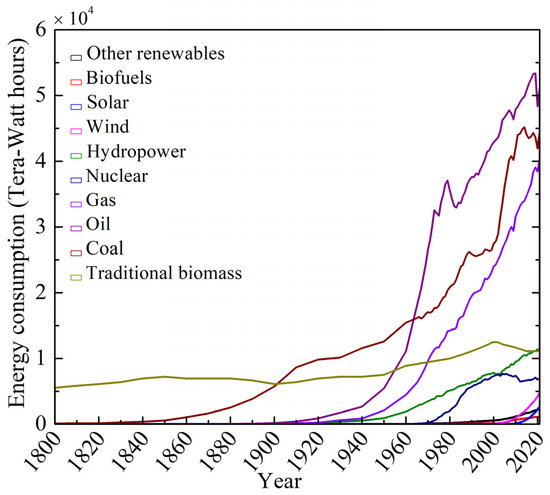
Figure 1.
World energy consumption trend [1].
While the most commonly known use of solar energy is through direct conversion to electricity using photovoltaic cells, this method is also costly. An indirect approach involves utilizing solar energy through flat plate collectors, solar collectors (concentrated), and SCPPs for electricity production or heating purposes. The SCPP system relies on three key effects: the greenhouse effect, the buoyancy effect, and the chimney effect. The greenhouse effect captures heat in the air, which then rises due to the buoyancy effect. The draft in the chimney drives the air flow through a wind turbine located at the chimney entry, converting the thermal energy into electricity using a generator [9,10,11]. SCPPs can be considered solar thermal power generation units that employ open solar air collectors and chimneys [12,13]. Unlike conventional power plants, SCPPs produce electricity without fossil fuels, thereby contributing to efforts in climate change mitigation. Moreover, SCPPs offer a sustainable energy solution by minimizing the ecological footprint and promoting environmental stewardship.
Scientists have been actively researching SCPPs for several decades, dating back to the 1960s. The study aimed to analyze and assess numerical and experimental studies conducted in this field. By examining these research matrices, researchers sought to recognize the current state of knowledge, research trends, and any existing research gaps related to SCPPs. The percentage of experimental work is not significant as the chart provided in Figure 2 as per the article searched by the authors. The data reveal that numerical studies have been rapidly increasing, while experimental work has progressed at a more consistent pace.
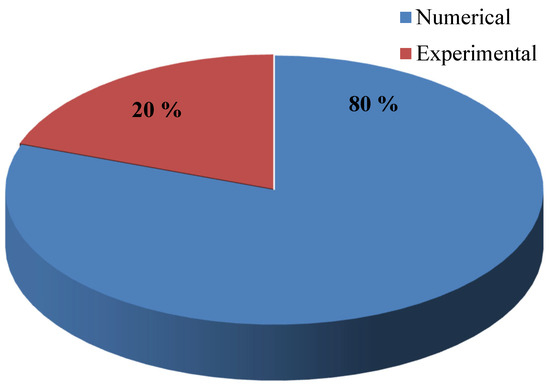
Figure 2.
Matrics of numerical and experimental works on SCPPs.
Review studies play a crucial role in the research community, providing updates on the current state of work in a particular field and serving as essential tools for researchers. The trend of review articles on SCPPs over the years is presented in Figure 3. Most of the studies mainly describe the basic principles, advantages, and disadvantages of SCPPs [14,15,16,17]. Some studies explore geometric modifications to enhance the performance of SCPPs [18,19,20], while others propose innovative designs [15,21]. Optimization through energy and exergy analyses has been investigated by [22], while cost analysis has been explored by Al-Kayiem and Aja [21] and Pradhan et al. [19]. Hybridization of SCPPs has also been reviewed in the current study [23,24] to achieve improved performance. A summary of all the reviewed articles can be found in Table 1. Notably, despite extensive research, SCPPs have yet to be commercialized. One common finding in the review work is the absence of detailed information on the experimental methods and instrumentation used. Further commercialization efforts require more comprehensive experimental investigations.

Figure 3.
The trend of review articles on SCPPs over the years.

Table 1.
Summary of different review works on SCPPs.
This comprehensive review paper aims to provide an in-depth analysis of experimental approaches and advancements in the fields. The paper then addresses the environmental impact and sustainability considerations associated with solar chimney power plants. Furthermore, endorsements for future exploration and improvement in the field are provided to guide researchers and industry professionals. This study may help to commercialize either the basic standalone or hybrid SCPPs. A summary of key findings from the review paper is presented. Additionally, future exploration and improvement recommendations are provided to guide researchers and industry professionals.
2. SCPPs: An Overview
2.1. Principles and Operation
The plant consists of several key components, including a chimney, absorber plate, collector, wind turbine, and generator (in Figure 4). The transformation of thermal energy from solar energy occurs through a series of processes between the collecting surface and absorber, utilizing the greenhouse consequence.
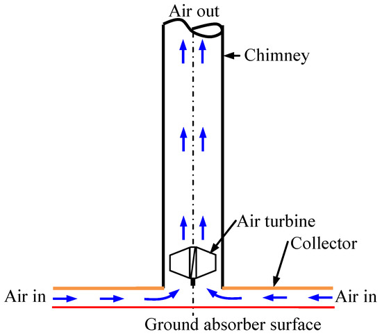
Figure 4.
Schematic diagram of SCPP.
The collector plate, typically made of glass coated with an anti-reflection material to reduce reflection losses, is transparent, allowing both direct and diffuse solar irradiation to pass through. After passing through the collector, the short-wavelength solar radiation falls onto a black-colored absorber wall. The absorber is designed efficiently to absorb the incoming solar irradiation, maximizing heat transfer.
As the lower absorbing surface absorbs the solar irradiative energy, the surrounding air becomes heated. This hot air gains thermal energy and subsequently converts it into kinetic energy within the wind turbine located in the chimney entrance location. The central chimney serves as a conduit, directing the hot air flow. At the entry to the chimney, the wind turbine is coupled with a generator, which converts the kinetic energy of the flowing air into electricity. This electricity generation process harnesses the thermal energy of the heated air flowing through the chimney, enabling the SCPPs to produce electrical energy [33].
2.2. Historical Development and Evolution
The renowned Italian genius Leonardo da Vinci (1452–1519) first proposed the concept of utilizing heated air in a chimney to run a windmill. His design involved a windmill that rotated a roasting spit above a fireplace [34,35,36]. Centuries later, in 1903, the concept of the SCPP was described by Spanish artillery colonel Isidoro Cabanyes. His apparatus consisted of an air-based heat exchanger fixed with a chimney base, with a wind propeller located at the top of the house to extract the electrical energy [37,38,39]. In 1926, Prof. Dubos suggested the building of an SCPP in North Africa. This design utilized the slant of a mountain [13,39]. The SCPP concept was further described by Hanns Günther and published in 1931, highlighting a chimney with an approximate velocity of 50 m/s [13,39,40]. In 1956, Ridley [41] was granted a patent for a design involving two chimneys. The air was heated in the first chimney, while cold air passed through a turbine at the first chimney. The wind turbine was placed at the outlet to the second chimney, which supplied cold air through the downdraft principle.
Another SCPP patent was granted to Nazare in 1964 [42,43]. The design featured a diffuser-shaped tower with a height of 100–300 m. After the oil crisis in the 1970s, there was a growing need for energy conservation and alternate energy sources, leading to increased research interest in renewable energy. During this period, several patents were granted to researchers, including Lucier between 1975 and 1981 [44,45,46,47,48]. The SCPP technology gained prominence again when Prof. Schlaich presented it at a congress in 1978 [49]. Schlaich and his group built the first prototype SCPP (Figure 5) between 1980 and 1982 in Manzanares, Spain, which was sponsored by the German Government and carried out in collaboration with the Spanish Utility Union Electrica Fenosa [12,50,51,52,53,54,55].

Figure 5.
Manzanares plant prototype [50]. (Reproduced with permission from Elsevier).
2.3. Advantages and Challenges
SCPPs have emerged as a promising and innovative solution for harnessing renewable energy, offering numerous advantages over traditional power generation systems. These advantages include:
- (a)
- Sustainability and Renewable Energy: SCPPs utilize abundant solar energy, providing a renewable source of power. This reliance on the sun’s rays ensures a continuous and eco-friendly energy supply.
- (b)
- Simple and Clean Technology: SCPPs employ a remarkably simple and clean technology, resulting in reduced capital and operational costs compared to conventional power generation methods. The absence of fossil fuels and cooling towers eliminates hazards and expenses, promoting a safer and more environmentally friendly solution.
- (c)
- Affordability and Feasibility: SCPPs benefit from the affordability of construction materials, making them attractive for regions with limited resources and governments/organizations aiming to transition to renewable energy. Lower building costs enable more feasible and cost-effective implementation of SCPPs.
- (d)
- Suitability for Remote Areas: SCPPs can operate independently, making them ideal for remote locations with limited access to power grids. This reduces the need for extensive infrastructure and helps mitigate infrastructural costs, particularly in areas with low land costs and sparse population density.
- (e)
- Repurposing Existing Infrastructure: Abandoned thermal power plant chimneys can be repurposed for SCPP installation, minimizing the need for new construction and maximizing resource utilization. This approach reduces costs and promotes sustainable reuse.
- (f)
- Long Operating Life: SCPPs have a longer operating life compared to many other power generation technologies. With fewer moving parts and minimal maintenance required (mostly the turbine), these power plants can operate efficiently for over 80 years.
- (g)
- Cost-effectiveness: SCPPs do not require fuel, resulting in reduced operational and maintenance costs. This makes power generation costs relatively inexpensive compared to fossil fuel alternatives, benefiting both consumers and the environment.
- (h)
- Environmental Benefits: SCPPs produce electricity without emitting smoke, pollutants, or greenhouse gases, making a positive contribution to combating climate change and minimizing the ecological footprint of energy generation.
However, along with these advantages, SCPPs also face certain challenges that have limited their widespread adoption:
- (a)
- Large Area Requirement: SCPPs require a significant land area for their construction, which may pose challenges in densely populated regions or areas with land scarcity.
- (b)
- Low Energy Production and Efficiency: SCPPs typically have lower energy production and efficiency compared to conventional power plants, which limits their overall power generation capacity.
- (c)
- Higher Initial Investment Costs: The initial investment costs for SCPPs can be relatively high, which may stop some investors or project developers.
- (d)
- Power Production Limited to Daytime: SCPPs rely on direct solar radiation, resulting in power production limitations to daylight hours only.
- (e)
- Longer Payback Periods: The return on investment for SCPPs may take longer compared to other power generation technologies, resulting in longer payback periods.
Despite these challenges, extensive research has been carried out to explore the potential of solar energy and generate significant interest in the development of SCPPs. These efforts aim to overcome the challenges and unlock the full potential of this promising renewable energy solution.
3. Experimental Design and Testing Methodologies of Standalone Plants
3.1. Design Modifications/Considerations for Solar Chimney Power Plants
Since the conversion efficiency of an SCPP is low, extensive efforts are being made to enhance its performance. In general, the effectiveness of an SCPP system depends on various parameters, including collector diameter, collector height, chimney area, chimney height, collector slope, junction at the chimney inlet, chimney shape, air temperature, collector material, absorber material, absorber nature, and solar radiation. Researchers have conducted extensive studies to modify SCPP systems based on these parameters, with a specific focus on optimizing the system geometry.
The absorber plate controls the system’s performance by absorbing radiation efficiently, which has been reported to enhance the power output of the collector [56,57,58]. Researchers have explored surface modifications of the absorber plate, including wavy, staircase, and bottom triangular designs, to enhance performance [10,11,59]. Among these designs, a single triangular-shaped absorber has shown superior performance. The choice of absorber material (refer to Table 2) depends on performance and cost considerations, with copper being widely used due to its high conductivity.
The collector plate, which allows solar radiation to pass through, can be made of different materials (refer to Table 3). Glass with anti-reflective coatings is commonly used as the optimal transparent collector material due to its ability to minimize reflection losses. The cost of used PVC material is less but not too much. Sloped collectors, with positive or negative slopes, have been investigated by various researchers. Positive slopes (refer to Table 4) have been found to improve performance up to a certain point. However, in many cases, higher slopes lead to increased vortex formation, resulting in higher losses and reduced performance. Thus, sloped collectors have an optimum slope angle that maximizes velocity and power output. For instance, Cuce et al. [60] reported that a sloped ground angle of 0.5° yielded the highest velocity and power output. Kasaeian et al. [61], Patel et al. [62], Ghalamchi et al. [63], and Yapici et al. [64] have studied the impact of collector inlet height on performance. Lowering the inlet height has been found to improve performance, but excessively low heights can lead to a decline in performance. The ground slope and shape both control the performance, as observed by a few researchers (Table 5).
Several researchers have observed that heightening the chimney can lead to improved effectiveness of SCPPs [65,66,67,68]. The chimney diameter also plays a significant role in power generation and efficiency, with larger diameters generally resulting in better performance. However, there exists an optimum value for the chimney diameter. Guo et al. [69] stated that electricity generation is optimal for chimney diameters up to 100 m, beyond which the increase in performance is negligible. Ramakrishna et al. [68] demonstrated the relationship between the ratio of chimney height-to-collector diameter and the efficacy of SCPPs, suggesting a recommended ratio in the range of 0.8 to 5 [70,71]. The impact of the diameter of the chimney is more significant than that of the height of the chimney, emphasizing the importance of proper design considerations (refer to Table 6). Kasaeian et al. [61] found that a 30 cm diameter chimney performed well in their study. The optimal slenderness ratio (the ratio of the chimney height to diameter) should be within the range of 6–8, as noted by Ming et al. [72]. Conversely, Petrorius [73] reported a best slenderness ratio of 5–6, while Zhou et al. [71] suggested a range of 6–8. Taking into account the effect of airflow, Kashiwa [74] proposed a slenderness ratio of 12, considering the performance enhancement.
Chimney shape also has an impact on the performance of SCPPs, with cylindrical, convergent, and divergent shapes being considered in the literature. Divergent-shaped chimneys (refer to Table 7) have shown better performance, and an optimum divergent angle has been reported by Nasraoui et al. [75], Das and Chandramohan [76], and Yapici et al. [64]. Patel et al. [62] found that an optimum divergence angle of 2° resulted in the best performance. Ohya et al. [77] reported that a divergence angle of 4° maximized the updraft, while Hassan et al. [78] and Nasraoui et al. [75] suggested optimal divergence angles of 1° and 3°, respectively. The chimney divergence is also measured by area ratio. The area ratio (AR), which represents the ratio of the chimney cross-sectional area to the chimney exit area, has been studied to determine its influence on power generation. The optimum AR for power generation is approximately 10 according to Hu et al. [79], 4 according to Cuce et al. [80], 16 according to Koonsrisuk et al. [81] and Lebbi et al. [82], 8.76 according to Xu et al. [83], and 12.39 according to Vieira et al. [84]. The optimum height of the chimney by divergent shape is addressed by Singh et al. [85]. The choice of chimney material is based on economic analysis. The selection of chimney material is typically based on economic analysis. Researchers consider various factors to determine the most suitable material for the chimney (refer to Table 8). Proper designing of turbines for improving power is carried out by Caicedo et al. [86]. There is passive ventilation work at chimney performance addressed by Zhang et al. [87]. The use of a double chimney has been noted by Abdelsalam et al. [88] for better performance.
Figure 6 depicts the modified SCPP after incorporating geometry modifications.
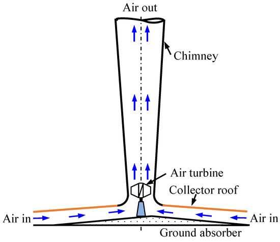
Figure 6.
Plant after geometry modification.
Table 2.
Absorber material used by different researchers.
Table 2.
Absorber material used by different researchers.
| Authors | Used Absorber Material |
|---|---|
| Sangi et al. [56], Xu et al. [89], Rabehi et al. [90], Gholamalizadeh and Mansouri [91], Shirvan et al. [92], Ramakrishna et al. [68,93], Amudam and Chandramohan [94] | Copper plate |
| Haaf et al. [95], Nizetic et al. [96], Hamdan [97], Al-Azawiey et al. [98], Abdelmohimen and Algarni [99], Kasaeian et al. [28] | Ground |
| Lal et al. [100] | soil |
| Bugutekin [101], Pasumarthi and Sherif [49,70], Ghalamchi et al. [63] | Aluminum plate, Iron plate |
| Nasirivatan et al. [102] | Concrete |
| Ayadi et al. [103] | Chipboard wood + steel |
| Cao et al. [104] | Granite |
| Al-Kayiem et al. [105] | Corrugated zinc plate |
Table 3.
Collector material used by different researchers.
Table 3.
Collector material used by different researchers.
| Authors | Used Collector Material |
|---|---|
| Haaf et al. [52], Xu et al. [89], Sangi et al. [56], Al-Dabbas [106], Raney et al. [107], Shirvan et al. [92], Papageorgiou [108], Guo et al. [20,109], Kasaeian et al. [28], Mekhail et al. [110], Ayadi et al. [103], Mohammed et al. [111], Mandal et al. [9] | PVF/PVC |
| Bugutekin [101], Najmi [112], Gholamalizadeh and Mansouri [91], Kalash et al. [113], Shahreza and Imani [114], Ohya et al. [77], Amudam and Chandramohan [94], Ramakrishna et al. [68] | Transparent glass |
| Hamdan [97], Rabehi et al. [90], Abdelmohimen and Algarni [99], Nizetic et al. [96] | Glass or Plastic film |
| Nasirivatan et al. [102], Ghalamchi et al. [63,115] | Free iron soda-lime glass |
| Lal et al. [100] | Transparent polyethylene |
| Al-Azawiey et al. [98], Ahmed and Patel [116], Al-Kayiem et al. [105] | Acrylic glass (Perspex) |
Table 4.
Collector slope used by different researchers.
Table 4.
Collector slope used by different researchers.
| Authors | Used Collector Slope (°) |
|---|---|
| Gholamalizadeh and Kim [117], Xu et al. [89], Guo et al. [69] | 2 |
| Zhou et al. [71] | 8 |
| Das and Chandramohan [58], Amudam and Chandramohan [94], Ramakrishna et al. [68], Mandal et al. [9] | 30 |
| Hassan et al. [78], Bugutekin [101] | 6 |
| Jafarifar et al. [118] | 5 |
| Cuce et al. [60] | 0.5 |
Table 5.
Ground slope/shape used by different researchers.
Table 5.
Ground slope/shape used by different researchers.
| Authors | Used Ground Slope (°)/Shape |
|---|---|
| Mandal et al. [10,119] | 0, 0.12, 0.24, 0.36, 0.48, 0.6 |
| Mandal et al. [10] | Wavy triangular |
| Biswas et al. [11] | Stair shaped |
| Cuce et al. [59] | Single triangular shape |
| Cuce et al. [60] | 0.1, 0.2, 0.3, 0.4, and 0.5 |
Table 6.
Chimney slenderness ratio by researchers.
Table 6.
Chimney slenderness ratio by researchers.
| Authors | Chimney Slenderness Ratio |
|---|---|
| Haaf [95] | 19.15 |
| Schlaich [12] | 8.26 |
| Pasumarthi and Sherif [49] | 15.63 |
| Pretorius and Kröger [120] | 9.38 |
| Nizetic et al. [96] | 6.71 |
| Fluri et al. [54] | 9.1 |
| Bernardes et al. [55] | 4.76 |
| Mostafa et al. [121] | 6.94 |
| Okoye and Atikol [122] | 10.71 |
| Zhou et al. [123] | 7.14 |
| Cao et al. [104] | 10.13 |
| Hooi and Thangavelu [124] | 16.67 |
| Cao et al. [125] | 7.44 |
Table 7.
Chimney divergence angle used by different researchers.
Table 7.
Chimney divergence angle used by different researchers.
| Authors | Chimney Divergence Angle |
|---|---|
| Patel et al. [62] | 1, 2, 3 |
| Ohya et al. [77] | 0, 2, 4, 6 |
| Chergui [126] | 2.4, 4, 7 |
| Das and Chandramohan [76] | 1, 2, 3, 4, 5 |
| Hassan et al. [78] | 0, 1, 2, 3 |
| Nasraoui et al. [127] | 2, 3, 6, 9 |
| Okada [128] | 4 |
Table 8.
Chimney materials used by different researchers.
Table 8.
Chimney materials used by different researchers.
| Authors | Used Chimney Material |
|---|---|
| Haaf et al. [52] | Concrete |
| Lal et al. [100], Ayadi et al. [103] | PVC |
| Ghalamchi et al. [63], Al-Kayiem et al. [129] Kasaeian et al. [28], Rabehi et al. [90], Gholamalizadeh and Mansouri [91], Sangi et al. [56], Shirvan et al. [92], Amudam and Chandramohan [94], Guo et al. [109], Ramakrishna et al. [93,130] | Polycarbonate |
| Xu et al. [89], Cao et al. [104], Abdelmohimen and Algarni [99], Nizetic et al. [96], Hamdan [97] | Reinforced concrete |
Geometry modifications have been employed to enhance the power output of SCPPs, although the improvements achieved are not significant and have certain limitations [21,25]. Despite its low efficiency, which is below 2%, the SCPP remains a promising technology for converting solar energy into electric power. To maximize solar energy utilization and overcome these limitations, hybridization has emerged as a new concept for SCPPs [21]. Various hybridization techniques have been proposed, including the integration of solar PV cells, waste gas, geothermal energy, biomass, solar ponds, heat exchangers, solar vortex generators, wind supercharging devices, cooling towers, and short diffusers.
The effectiveness of SCPPs can be improved by utilizing waste heat from industries [131,132]. Photovoltaic (PV) cell integration significantly raises the performance of the plant. The PV cell can be placed on the collector transparent wall in a discrete manner or on the bottom absorber wall of the SCPP [133,134,135,136]. Biomass waste flue gas can be utilized to heat the air, and a geothermal integrated plant combines a geothermal well with a solar chimney plant [137]. Solar ponds, which deliver hot water into the chimney through pumps and spray the water to heat the air, can also be used [138]. Other techniques for improving SCPP performance include solar vortex generators [129], heat exchangers [139], and desalination units [140,141]. The various types of hybridization are illustrated in Figure 7.
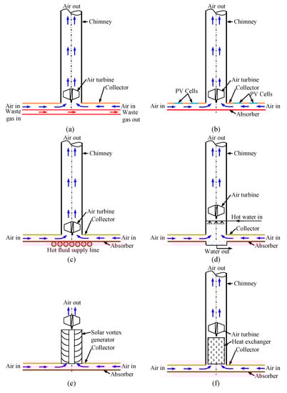
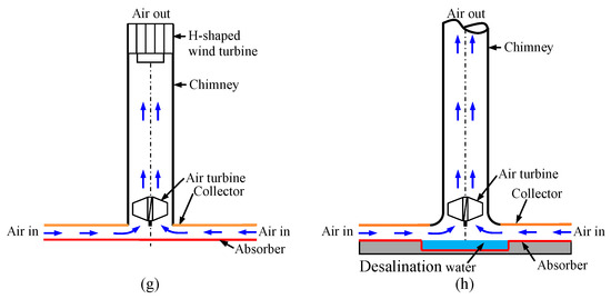
Figure 7.
Different methods of hybridization used in SCPPs: (a) waste gas, (b) photovoltaic (PV) cell, (c) geothermal/biomass sources, (d) solar pond, (e) solar vortex generator, (f) solar chimney plant with heat exchanger, (g) wind supercharging, and (h) integration of desalination unit.
3.2. Prototype Development and Scale Modeling
A summary of experimental work conducted on SCPPs is presented in Table 9. It is evident from the geometric dimensions of the studied plants that most of the research has been limited to small-scale laboratory experiments. Since the establishment of the large-scale plant in Manzanares, Spain [52], there have been no further significant attempts to build large plants for generating substantial power. The focus of the studies has primarily been on measuring the velocity and temperature enhancements due to the greenhouse effect, although these have been theoretically correlated with power generation. Some researchers [40,101,112,142,143] have made efforts to explore larger chimneys with increased collector areas. Various laboratory experiments have utilized different scales of large geometries to gain insights into geometry optimization.
Table 9.
Experimental works of standalone SCPP by different researchers.
The prototype study by Pasumarthi and Sherif [49] investigated three configurations (Figure 8) by altering the collector size and shape. In the second configuration (Figure 8b), the collector area is increased radially, whereas in the third configuration (Figure 8c), a canvas absorber surface is connected below the collector.
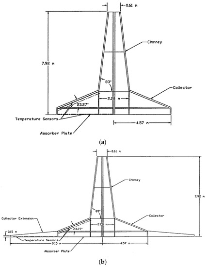

Figure 8.
Three configurations by Pasumarthi and Sherif [49]: (a) 1st geometry, (b) 2nd geometry, and (c) 3rd geometry. (Reproduced with permission from John Wiley and Sons).
The ground was prepared using sand as a filler. A 6 cm thick concrete pad with a diameter of 25 m was made for the collector supports. A black-painted aluminum plate was used as an absorber, and a 54 cm thick layer of styrofoam insulation was laid between the absorber plate and the concrete to mitigate heat loss. In the experimental study by Zhou et al. [71], the insulation materials were placed below the absorber, consisting of 25 cm of mixed black gravel and asphalt. The base of the chimney was connected with a detachable cylinder fitted with a flange connection (shown in Figure 9a). Inside the cylinder, the turbine and a generator were positioned. The ground absorber [101] consisted of a 0.5 m depth pit enclosed with an aluminum sheet and a 0.05 m thick glass sheet for storing heat during daylight in the ground base. The ground was composed of asphalt (0.25 m), gravel (0.25 m), sand (0.25 m) and compressed, as shown in Figure 9b. The foundation (Ahmed and Patel) [116] of the unit was 1 m depth (shown in Figure 9c).

Figure 9.
(a) Chimney base, Zhou et al. [72] (Reproduced with permission from Elsevier); (b) layered ground, Bugutekin [101]; and (c) foundation; Ahmed and Patel [116] (Reproduced with permission from Elsevier).
The plant developed by Ramakrishna et al. [68] consisted of a concrete foundation, 4 m in diameter and 10 cm thick. The ground base was made using a combination of sand, cement, and rock gravel. It was supported by eight foundation rods made of SA36 material, which were clamped onto the concrete foundation, as shown in Figure 10a. To lessen the heat losses from the bottommost part of the thermal energy storage (TES) plate to the atmosphere, the bottom plate was fitted with thermocol sheets and a 25 mm thick plywood layer. The TES device had a total thickness of 150 mm, including the wood-based board, thermocol, and a combination of rock gravel and sand (depicted in Figure 10b). The upper surface of the bottom wall was covered with a copper absorber plate that was painted black. The surface of the collector area was enclosed with anti-reflective glazed glass (5 mm thick) to prevent reflections and optimize solar radiation absorption.

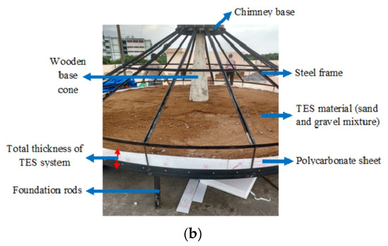
Figure 10.
(a) Total plant and (b) bottom shape of Ramakrishna et al. [68] (Reproduced with permission from Elsevier).
In the investigation of Kasaeian et al. [139], the collector was constructed using 48 pieces of 4 × 4 steel structure connected to the base inside the concrete. To provide mechanical strength, transparency, toughness, heat resistance, and UV resistance, the collector was covered with polycarbonate (PC) sheets. Two layers of PC sheets were used to enhance the greenhouse effect and minimize losses. Mehla et al. [146] used a fiber-reinforced plastic material with a transmission rate of 93% to cover the collector and achieve the greenhouse effect. An insulating material was placed below the absorber to minimize heat loss. Bugutekin [101] developed a sloped collector using a 0.004 m thick glass, while the chimney was made of a 0.07 m thick metal plate. The chimney was covered with a 0.05 m thick layer of aluminum foil and glass wool to prevent thermal losses.
Figure 11 shows an experimental setup conducted by Motoyama et al. [147] in a room. Artificial heating was used to heat the ground unit, which consisted of a 1.5 m × 1.5 m steel plate (9 mm thick). The setup included eight 375 W heaters placed at the bottom of the ground unit.

Figure 11.
Experimental model and schematic diagrams (Motoyama et al. [147]).
Amirkhani et al. [148] used two layered polycarbonate sheets applied as the collector sheets and black polyethylene film covers on the ground to achieve maximum radiation absorption. In their (Shahreza and Imani) [114] novel small-scale model, an intensifier in the form of a flat mirror was utilized to strengthen the solar radiation at the center of the canopy, as shown in Figure 12.
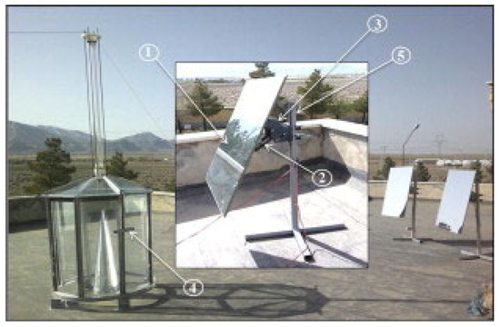
Figure 12.
Experimental test setup of SCPP with (1) flat-type mirror, (2) holding arrangement, (3) DC motor unit, (4) sensors, and (5) mirror-holding stand [114]. (Reproduced with permission from Elsevier).
In the study conducted by Lal et al. [100], the primary assembly of the prototype comprised steel structures, with 12 legs grouted on the ground surface. Two sloped collectors were covered with transparent polyethylene, and the chimney was made of PVC. Ghalamchi et al. [63] used 15 pieces of steel profiles to construct the prototype. The low-iron soda-lime glass, combining 8 circular glass pieces with a thickness of 3 mm, was utilized to build the collector. The ground material consisted of steel and wood. Al-Azawiey et al. [98] utilized Perspex for the collector with a canopy, while the absorbing surface was composed of a ground surface roofed with black-painted pebbles. The chimney 6.3 m in height was made of 15.25 cm thick PVC.
Ahmed and Patel [116] constructed the collector frames using a 40 mm × 40 mm × 1.6 mm size square tube made of galvanized steel. The collector was covered with 6 mm Perspex and secured with eight M16 high tensile bolts. The chimney was created by rolling a 1.6 mm thick galvanized metal sheet into a cone-shape, consisting of three sections, each 1200 mm in length, welded collectively to form a 3600 mm height chimney. The solar collector roof, as described by Eryener et al. [143], comprised a solar collector (transpired) and a glazy polycarbonate unit. The solar collector’s top surface was fully covered, allowing outside air to enter the collector through the micro-holes.
Mekhail et al. [110] used a smaller test rig consisting of a plastic (of thin sheets) made collector surface. A pipe was utilized to fabricate the chimney (having 0.15 m diameter and 6.0 m height). The collector was supported by a steel structure with a wood-based network. Nasraoui et al. [127] utilized an adhesive film of polyethylene as the material for the collector roof. The PVC chimney (with a thickness of 3 mm) was supported by a steel structure. For absorbing the substantial amount of solar radiation, a platform (of black rubber) was placed on the ground. In the study of Mehla et al. [149], a convergent chimney made of sheet metal was used, and the collector was composed of a greenhouse plastic sheet made of polyvinyl fluoride (PVF) polythene (transparent). Mild steel square bars supported the collector structure, and four types of absorbers were tested: black PVF polythene, stone, gray sand, and water units. Mandal et al. [9] implemented an experimental prototype consisting of a plastic-covered MS ground plate and PVC pipe to assess the SCPP performance.
Golzardi et al. [152] conducted an experimental study considering two setups to evaluate the collector inlet height impact (Figure 13). The setups were scaled at 1:100 compared to the Manzanares plant. Solar radiation in both setups was delivered by an adjustable heater, which simulated different solar radiations.
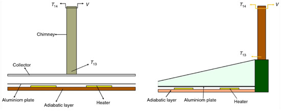
Figure 13.
Two setups by Golzardi et al. [152]. (Reproduced with permission from Springer Nature).
Uncertainty analysis is a crucial aspect of experimental work as it addresses the variability in instrument readings at a given point in time. In such cases, the arithmetic mean (xm) is calculated using the readings denoted as xi, with n representing the total number of readings. To determine the deviation in each reading , the difference between each reading and the mean value is calculated. These deviations are then used to calculate the standard deviation (σ) by considering the squared differences, summing them up, dividing by the number of readings (n), and taking the square root of the result. Additionally, the standard deviation of the mean (σm) is computed as:
σ is the standard deviation.
√n is the square root of the number of readings.
- where the uncertainty of the data sets is . This provides an indication of the variability or potential errors in the data. The uncertainties discussed in various experiments mentioned above have been duly recognized and considered during the analysis.
3.3. Instrumentation and Measurement Techniques
The instruments required for SCPP experimentation mainly include temperature measurement devices, velocity measurement devices, irradiation measurement devices, and a turbine speed measuring device. The positioning of the air velocity sensor and temperature sensor is important for effective measurements in any plant. For temperature measurement, LM34 sensors were used to measure 32 air temperatures, with eight sensors placed along the chimney length, as described by Pasumarthi and Sherif [49]. Zhou et al. [123] utilized PT 100-type platinum resistance thermometer sensors for measuring the temperature of air at 12 specific locations, as shown in Figure 14a. To measure the air velocity, an anemometer (thermal type) with an accuracy of ±0.01 m/s was utilized. All measured data were stored in a data-logging device. In the work by Motoyama et al. [147], a similar type of PT100 sensor was fixed to the center of the panel, and the temperature of the iron sheet was monitored by a control panel as required. The airflow velocity in the developed model was measured using an ultrasonic anemometer placed at the chimney, positioned at a height of 5 cm from the air turbine blade. The velocity signal was fed to a PC and monitored using software.
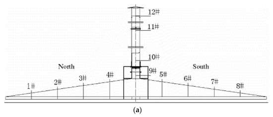
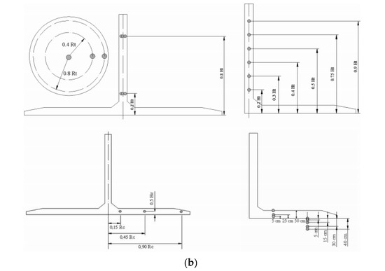
Figure 14.
(a) Temperatures at 12 typical points as measured by Zhou et al. [71] (Reproduced with permission from Elsevier) and (b) sensor location as indicated by Maia et al. [142] (Reproduced with permission from Taylor & Francis).
Ahmed and Patel [116] used PT–100 temperature sensors ranging from −200 °C to 400 °C (having a resolution of 0.1 °C) for measuring the air temperature. All temperature points were connected to a DaqPRO data-logger with a correctness of ±0.5%. They also employed a Chromel-Alumel type K thermocouple ranging from −200 °C to 1260 °C and a Center-305 data-logger thermometer with an accuracy of ±0.75% for temperature measurements. In the experiment conducted by Maia et al. [142], K-type thermocouples (eight types) were used for measuring the temperatures inside the collector, chimney, and outside. Propeller anemometers were employed for measuring the air speed through the chimney, and incident solar radiation was checked using seven Eppley pyranometers (black and white). All sensors were connected to an ADAM-4018 unit for measuring the velocity, humidity, temperature, and solar radiation (shown in Figure 14b). Ahmed and Chaichan [144] utilized six K-type thermocouples spread equally along the chimney to measure the temperature of the air. Eryener et al. [143] used eight temperature sensors connected in the midpoint of the air container and one-speed sensor fitted in the chimney center.
Kasaeian et al. [145] utilized SMT-160 sensors. In the data-logger, all the recorded data were stored. They have considered twelve temperature sensors, with four sensors positioned inside the chimney and eight sensors positioned on the collector surface. The velocities of hot air inside the chimney were tested using an anemometer (model AVM702). Mehla et al. [146] employed a digital thermal anemometer (having an accuracy level of ±0.01 m/s) for measuring air velocity. Bugutekin [101] installed ten thermometers (ranging from −50 °C to 150 °C and a sensitivity of ±0.01 °C) on the collector surface and chimney for measuring the air temperature. Additionally, five infrared-type thermometers were utilized for measuring the soil temperature. Homis anemometers were employed to measure air velocity, and a CMP21 model pyranometer was used for solar radiation measurement. The temperature distribution of the ground plate was measured using a laser thermometer at different points (as in Figure 15a).
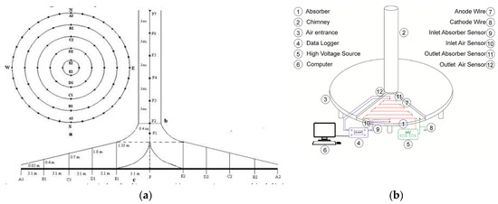
Figure 15.
(a) Air temperature points at the collector (Bugutekin [101]) and (b) solar chimney structure (Nasirivatan et al. [102]) (Reproduced with permission from Elsevier).
In their experiment, Nasirivatan et al. [102] applied an electric field between the anode (wired setup) and cathode (absorbing surface) for heating. The collector was made of soda-lime glass (iron-free), and the absorber surface was made of steel combining the wooden chipboard covering with opaque black. A polycarbonate sheet (4 mm thick, 2 m long) with a diameter of 20 cm was utilized for chimney construction. Both the absorber and collector were positioned on a concrete base (as shown in Figure 15b). Four SMT-160 sensors were utilized for measuring the temperatures at the entry, exit, and absorbing plates. A hot-wire anemometer (model YK-2004AH) was used to measure air velocity inside the chimney. A pyrometer (Kipp and Zonen-CM11 model) was utilized for measuring solar irradiation. Amirkhani et al. [148] also used SMT-160 sensors to measure temperature. Five sensors (positioned at a distance of 1 m) were placed 10 cm above the absorbing surface. Using an AVM-702 anemometer, the air velocity within the chimney was measured. The speedometer propeller was located at the chimney entrance, where the airflow velocity was maximum. The measured data were stored in a data-logger. Mekhail et al. [110] measured temperature at four locations using K-type thermocouples.
In the indoor experiment and scale model conducted by Ohya et al. [77], the setup was made of a translucent acrylic sheet. The chimney had a rectangular shape, and fog was sent through the chimney while capturing images using particle image velocimetry (PIV) measurements. The experimental system included temperature control of the top exterior of a copper metal sheet arranged above the floor. The velocity of air was captured using an anemometer (I-type hot-wire). Laboratory experiments carried out by Okada et al. [128] utilized a solar tower setup (Figure 16). An anemometer (ultrasonic-type) was placed 50 mm beyond the wind turbine, and the signal from the anemometer was recorded and analyzed using fast Fourier transform (FFT) algorithm on a PC.

Figure 16.
Laboratory experiments conducted by Ohya et al. [77].
In the study by Lal et al. [100], a solar pyranometer (Model: SP Lite-2, Make: Kipp & Zonen, Delfi Poland) was utilized for measuring solar irradiation. For measuring the air temperature K-type thermocouples were adopted at different positions. A hot-wire anemometer was utilized for measuring the air. The instruments were maintained within an uncertainty of ±0.17. Al-Azawiey et al. [98] used thirteen J-type thermocouples for measuring the temperature at different locations, including the absorbing plate, transparent cover, air within the chimney, air within the collector surface, and atmospheric air. A GRAPHTEC 820 data-logger was utilized for recording all temperatures. The air velocities at different positions within the chimney were recorded utilizing a hot-wire probe anemometer (having an accuracy of ±3% of reading or ±0.03 m/s). A KIMO solarimeter (SL200) was employed for global solar radiation measurements, with a measuring accuracy of ±5%. Ahmed and Patel [116] measured solar insolations using a Licor LI200S Pyranometer, with a deviation of 1% (maximum), for solar radiation up to 3000 W/m2. The pressure was measured using an FCO510 digital micromanometer. Mekhail et al. [110] measured solar radiation by means of a protective glass dome and solar shield (pyranometer) with an uncertainty of ±0.1 W/m2. The turbine speed was measured by means of an Extech 461895 contact/photo tachometer, with an accuracy of 0.05%.
Mehla et al. [149] measured the temperature at different positions of air using temperature detector (RTD) PT100 sensors (platinum resistance type), while a sling psychrometer was utilized for measuring the dry bulb temperature of the ambient air. They utilized a pyranometer (Model CM11) and an anemometer (AM-4208) for measuring solar irradiation and air velocity. The specifications of the instruments are provided in Table 10.
Table 10.
Specification of the instruments used by Mehla et al. [149].
In a recent study, Khidhir [150] utilized an eight-channel temperature data-logger V2 (well-matched with Arduino Bluetooth Module HC-05), for measuring temperature. This data-logger was connected to a computer through a data acquisition system (DAS) for recording according to the programmed time setting. Twelve temperature sensors, specifically DS18B20 type three-wire type, were employed for measuring the temperature at various locations along the collector radius, collector elevation, and chimney height. The measured temperature was recorded using the eight-channel data-logger V2 connected to the computer. The uncertainty in these sensors was ±0.5 °C over a temperature range of −50 to 125 °C. The air velocity within the chimney was measured by a GM8901 anemometer. Solar radiation was measured using a Hukseflux thermal sensors LP02 pyranometer with a calibrated uncertainty <1.8%.
Ramakrishna et al. [68] used various instruments, and the details are presented in Table 11.
Table 11.
List of instruments and their specifications used by Ramakrishna et al. [68].
In the study of Mohammed et al. [111], air temperatures at six typical points of the collector were measured using an infrared thermometer. The velocity of air was measured using a thermal anemometer (having an accuracy of ±0.5 °C and ±0.01 m/s). Twelve Sunward 15-T1-type thermocouples were positioned under the collector for measuring temperature with a precision of 0.1 K, as described by Golzardi et al. [152]. Similar thermocouples were placed to measure the air temperature inside the chimney and ambient air temperature. To measure the air velocity, an anemometer with a precision of 0.01 m/s was utilized.
In an experimental prototype by Mandal et al. [9], which involved a plastic-covered MS ground plate and PVC pipe, an instruments list (see Table 12) with their specifications was mentioned. Table 13 shows the summary of instruments (type/model) used by different researchers.
Table 12.
List of instruments.
Table 13.
Summary of instruments (type/model) used by different researchers.
4. Experimental Design and Performance Analysis of Hybrid Plants
As the SCPP technology is simple in structure along with the lower operating cost for generating clean and renewable energy, such a technique is popular in developing countries. However, lower conversion efficiency, higher capital investment, and longer payback periods restrict its large-scale applicability. Although several research groups attempted numerically to enhance power generation using the SCPP by introducing various geometrical modifications. Some of them may not work in reality. To overcome this difficulty, the concept of hybridization of the SCPP integrating photovoltaic (PV) cells, geothermal energy, solar pond, desalination plant, etc., is a more promising approach for maximizing clean power production as well as drinking water generation for the local residents. There are very few works on this hybrid SCPP. In this section, a glimpse of the experimental work on the analysis of hybrid plants is scrutinized systematically.
4.1. Case Studies of PV-Cell-Integrated SCPP
In the recent past, Eryener et al. [153] conducted an experimental investigation on the hybrid updraft solar tower integrating transpired solar collector and photovoltaic panels (42% of solar collector area), which was installed at Trakya University in Edirne, Turkey, in 2015 (as shown in Figure 17a). Ambient air enters the arrangement through the perforations in the transpired solar collector (TSC). The heated air then passes through the tower and produces electricity (Figure 17b). The roof of the collector consisted of a solar collector (transpired), PV panel, and glazy polycarbonate panel. The polycarbonate panel allows daylight to the ground. The boundary of the collector was completely sealed, and air entered through the collector. A total of 28 PV panels having a capacity of 265 W each were placed on the polycarbonate panel area. Twelve numbers of SHT11 temperature and humidity sensors (Sensirion SHT11, range: −40 to 128 °C, accuracy: ±0.4 °C) were used at different locations. Eight sensors at two-meter intervals over the collector and three sensors were used at the tower entry, and the remaining one sensor was used for measuring the ambient temperature. A pyranometer (CM6B) was positioned horizontally at the entry of the solar chimney for measuring solar radiation. One velocity sensor (E+EEE671, range: 0–20 m/s of −20 to 60 °C) at tower entry and two pressure sensors (Bosch BMP180, range: 300–1100 hPa of −40 to 85 °C) before and after the turbine were used. They observed a 2% enhancement in the efficacy of the hybrid solar updraft tower related to the standalone PV unit. Finally, hybrid solar power generation efficiencies were enhanced up to 16–18% compared to conventional solar towers.
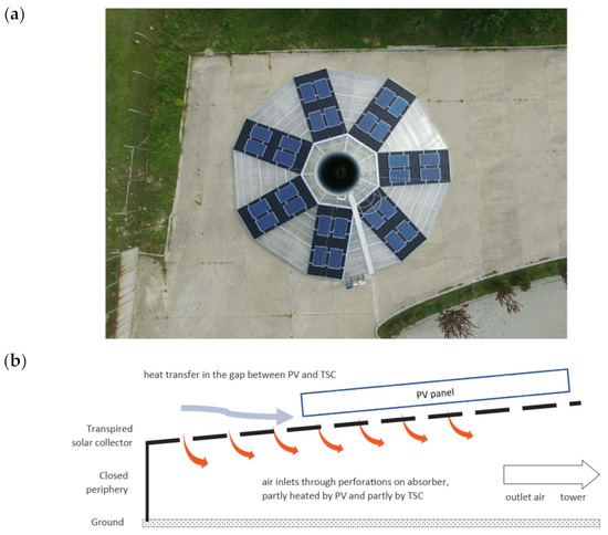
Figure 17.
(a) Prototype experimental setup; (b) mechanism of basic heat transfer of hybrid SUT; Eryener and Kuscu [153]. (Reproduced with permission from Elsevier).
Ahmed and Hussein [154] experimentally assessed the performance of a hybrid SCPP integrated with PV cells at Kirkuk, northern Iraq. They considered two experimental systems (Figure 18) of a rectangular duct, having a cross-sectional area of 67 cm × 10 cm, which was attached at the end of the bottom duct for working as a chimney (of size 2 m length and 0.67 m wide). In one setup, the PV panel was located at the collector and the other at the absorber. The solar PV panel, 148 cm long and 67 cm wide, was positioned inside an aluminum box. A 4 mm thick transparent glass cover at a distance of 10 cm from the solar panel covered the collector.
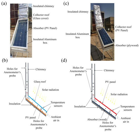
Figure 18.
Experimental model diagram for Setup 1 (a,c) and Setup 2 (b,d); Ahmed and Hussein [154]. (Reproduced with permission from Elsevier).
Five digital sensors along the air stream, two sensors on the collector, two sensors on the absorber, and two sensors on the back of the insulation were fixed for temperature measurement. A hot-wire anemometer (MY-300) was attached to four holes at the duct to measure the velocity of the air. Two multi-meters (SM-20) were fixed for measuring electric current and voltage. To measure solar radiation, a solar power meter (Solar Meter SM206) was connected at the same height as the solar panel. The PV panel at the collector wall showed better performance.
Both experimentally and numerically, Huang et al. [155] studied a hybrid SCPP combining photovoltaic cells for cleaning polluted air. In their setup, the chimney height was 205.5 cm with a diameter of 8 cm. The diameters of the collector and inlet/outlet height of the collector were 260 cm, 3.5 cm, and 10 cm, respectively. The test was conducted in a test room enclosed by rock wool-based sandwich panels and a toughened glass wall. A solar simulator (having an emitting radiation spectrum of 0.3–2.5 μm) was used to pass the solar rays through the glass wall. A sensor (PTWD-2A) with a radiation shield was used to measure the environmental temperature and humidity. The toughened glass wall temperature was measured by four sensors (PTWD-2A). A lower-pressure mass flow meter (MF80GD-160) was utilized to control the airflow rate in the chimney, and a solar power meter (TBQ-2A) was used to measure the irradiation inside the test room. From the experimental results, they observed a reduction in airflow rate by up to 14% by covering 50.60% acrylic glass with photovoltaic panels. However, with this arrangement, electric power generation increased markedly. They concluded that the installation of PV cells at the bottom of the collector corresponds to the increase in the bottom airflow rate by 2.42 times.
Considering a photovoltaic panel-based hybrid SCPP, Hussam et al. [156] experimentally and numerically examined the power generation efficacy utilizing solar energy in Kuwait. Their experimental test setup comprised an inclined rectangular collector (of size 0.67 m × 0.01 m × 1.5 m) integrated with a PV panel and a thin transparent glass cover over the collector (in Figure 19). The lower and collector inner walls were isolated. A chimney 2 m tall and 20 cm in diameter was vertically fixed with the collector through a converging nozzle. The velocity of air within the collector and the duct were measured with three Benetech GM8903 hot-wire anemometers (ranging from 0 to 30 m/s, accuracy of 3% ∓ 0.1, resolution of 0.001 m/s). Four type E thermocouples were positioned on the panel surface. The thermocouples were linked to a digital thermometer/data-logger (Omega OM-HL-EH-TC). A solar power meter (TES 132) recorded the solar radiation data every 10 min. They achieved 9–11% efficiency in the power generation with the hybrid system compared to typical SCPP efficiency. On the other hand, they obtained 18% enhanced power generation related to the standalone PV panel.

Figure 19.
Test setup of Hussam et al. [156].
For further improvement in the performance as well as large-scale commercial application of a hybrid SCPP integrating PV panels, more experimental studies are of utmost importance. Such studies are very limited to hybrid SCPP systems. Therefore, this area invites future researchers for further improvements.
4.2. Case Studies of Geothermal-Integrated SCPP
There are plenty of opportunities for improving SCPPs by combining different hybrid techniques, for example, geothermal energy utilization. Elghamry and Hassan [157] conducted an experimental investigation on a combined solar chimney, PV panels, and geothermal energy heated air for building cooling as well as ventilation process in new Borge Alarb city, Alexandria, Egypt. Their experimental setup comprised an insulated wooden room having a 2 m × 2 m square cross-section and 2 m height (3 cm thick). There was a window opening of 0.8 m × 0.8 m in size made of clear glass type and positioned at the midpoint of the north wall (as in Figure 20a). At the roof of the room, a solar chimney (south oriented) of size 1.6 m long, 0.7 m wide was installed with air gap thicknesses of 0.3 m inclined at 30° or 45° with a horizontal base. A natural as well as forced airflow through the geothermally heated tube system was utilized for the cooling and ventilation of the room (as shown in Figure 20b). The temperature of the air was measured by using thermocouples of type K at the entry and exit of the SCPP and three points on the PV module. The measured signals from all the thermocouples were stored in an NEC data-logger. The solar intensity was checked by a pyranometer (type Sigma 360), and the velocities of air at different locations of the solar chimney and geothermal tube were tested using a hot-wire anemometer. A digital Avometer was used for the voltage and current output measurement from the PV cell. They observed that at a 30° inclination angle of the chimney PV module output outside, the chimney is 120 W/m2. Furthermore, using the combined geothermal heated air system, the room could be cooled up to 3.5 °C, and the air was changed 42 times daily. They also observed that the least air ventilation happens with a natural geothermal tube–chimney arrangement when the chimney inclination is 30°. Daily heat release rate from the room occurred at a 45° chimney orientation with a normal geothermal tube–chimney–PV system.
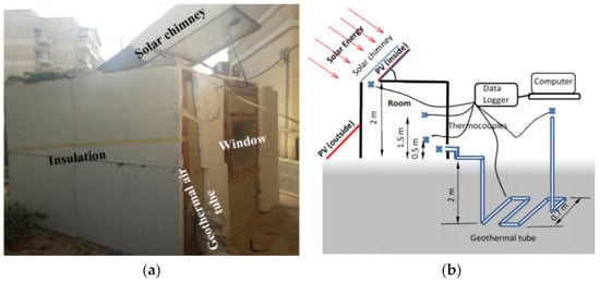
Figure 20.
(a) Solar chimney with PV-system-integrated setup and (b) schematic diagram of the setup; Elghamry and Hassan [157]. (Reproduced with permission from Elsevier).
Combining an SCPP (of 8 m height with 0.2 m diameter and 12 m collector diameter) and geothermal hot water (as an additional heat source), Mokrani et al. [158] experimentally investigated the performance of a hybrid SCPP at Ouargla University. A geothermal hot water pipe was arranged spirally within the collector to assess the impact of geothermal heating during the night to continue the power generation (in Figure 21a). They took inlet hot water at 80 °C with 3 L/s through a 0.016 m diameter tube (in Figure 21b). During the daytime, they achieved 68.3 °C temperature due to solar irradiation heating, and the velocity of air reached 5.8 m/s. However, combining solar irradiation and geothermal hot water led to a temperature of 80 °C with an air velocity of 7.1 m/s and, therefore, higher power generation. Their study clearly illustrates the potential of geothermal hot water for enhancing the performance of a hybrid SCPP. Seven K-type thermocouples (Nickel-Chromium/Nickel-Alumel, accuracy of ± 0.1 °C) inside the SCPP and one outside were used to measure the temperature distribution. A MacSolar (SLM018 c-E) solar meter and a propeller anemometer (UNI-T 361) were used for measuring solar intensity and air velocity, respectively.
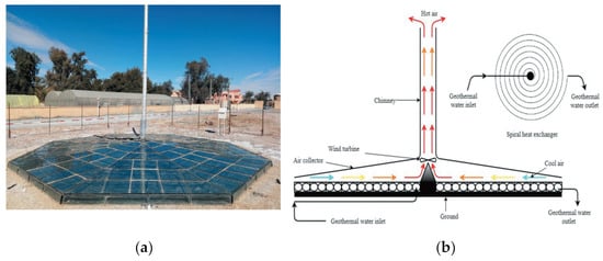
Figure 21.
(a) Hybrid SCPP tests setup, and (b) schematic arrangements of the setup; Mokrani et al. [158]. (Reproduced with permission from Taylor & Francis).
Yu et al. [159] experimentally assessed the SCPP performance by adopting a geothermal cooling process through an earth-to-air heat exchanger in Omaha, Nebraska, USA. They have considered 57 m long and 0.45 m diameter culvert steel and buried the same at 3 m deep beneath the grade. The test setup comprises a one-story building of outer size of 19.4 m length, 4.9 m width, and 3 m height. They constructed a solar collector with an absorber area of 20 m2, solar irradiation of 400 W/m2. A solar chimney of height 12.2 m and diameter 0.457 m was fitted with the room to produce the draft >5 Pa at 57 °C temperature. The test run was carried out for 43 days. T-type thermocouples with an accuracy of ±0.1 were connected to measure coil temperature, indoor air temperature, outdoor temperature, supply air temperature, and exhaust air temperature. Dwyer air velocity transmitter was used for air velocity measurement. From the experimental results, they observed that a combined geothermal system and solar chimney could provide effective cooling of the room without any electricity consumption. During the daytime, the solar chimney improves the airflow rate into the system due to the stronger solar irradiation. The cooling effect of the combined system reduces rapidly after circulating the forced airflow, which is due to the rise in the temperature of underground soil.
4.3. Case Studies of Heat-Exchanger-Integrated SCPP
Combining the concept of a heat exchanger with a modified SCPP, Aliaga et al. [139] both numerically and experimentally examined the efficacy of a modified SCPP. Their experimental setup comprised a 2 m height chimney duct (made of stainless steel) and a 0.15 m diameter. A cylindrical-shaped heater (of 2000 W capacities) of 0.07 m in diameter and 0.5 m in length was placed inside the chimney. For concentrating the solar energy, flat mirrors were arranged externally, and they supplied the heat to the heat exchanger placed inside the chimney. The hot air flowed through the chimney and rotated the wind turbine located inside the solar chimney. The prototype tower was implemented in the laboratory. The temperatures of the heater casing by a K-type thermocouple and several T-type thermocouples at the chimney axis for plume temperature were used in the experimental setup. Their prototype test setup as well as computational model (with a difference of <6.2% on power generation) ensures higher power generation compared with the classical model based on a simple solar chimney of similar dimensions.
4.4. Case Studies of Phase-Change Material Integrated SCPP
Fadaei et al. [160] experimentally examined the influence of phase-change materials on the overall efficacy of a hybrid SCPP at the University of Tehran. They constructed a solar chimney considering 3 m tall and 3 m collector dia. The polycarbonate pipe having 20 cm diameter and 4 mm thick was utilized for constructing the chimney. An iron-free glass of 3 mm thick plate was used for the collector roof. Paraffin was utilized as a phase-change material (PCM). A total of 16 sensors (2 sensors in the chimney, 7 sensors on the collector, 6 sensors at the absorbing surface and PCM surface, and 1 ambient) of type SMT-160 were used to measure temperature. All these data were stored on a micro-SD card by a data-logger. From the results, they observed that the extreme temperature of the absorber surface with PCM and the classical SCPP were 72 °C and 69 °C, respectively. Accordingly, the air velocity varies as 1.9 m/s (for the conventional chimney) and 2 m/s (in the presence of PCM). They concluded that adopting PCM as latent heat energy storage leads to a greater average mass flow rate (~8.33%) and thus higher power generation. Therefore, a hybrid SCPP adopting PCM as an energy storage media always improves the overall performance and power generation of the SCPP.
4.5. Case Studies of Thermal Power Plant Integrated SCPP
Various researchers have attempted to hybridize and improve the conventional SCPP. In this regard, the utilization of exhaust gases from fossil-fuel-fired power plants may be utilized as an alternative source for enhancing the power generation from the conventional SCPP. Shahdost et al. [161] conducted both a numerical and experimental study of an SCPP model combining the exhaust flue gases from a fossil-fuel-fired power plant. In the prototype model, they took a 3 m and 10 cm diameter chimney. The flue exhaust gas at a high temperature entered the chimney base through a 5 cm diameter pipe. Here, the collector was not required as heat was supplied from the power plant exhaust gas. The combination of the buoyancy effect due to the hot exhaust gases and ambient air generated a higher fluid flow at a higher fluid velocity. For measuring the temperature and velocity of the fluid, thermal sensors (model SMT-160) and hot wires (model YK-2004AH) were attached at different locations. The use of the exhaust flue gases from the conventional power plant enhanced the overall efficiency of the SCPP and thus higher power generation. Such a hybrid system is capable of producing electricity during the nighttime as well as when the power plant is operational. The hybridization of the conventional SCPP substantially reduces the capital cost of the SCPP because of the removal of the collector’s cost.
4.6. Case Studies of Desalination-Integrated SCPP
Zuo et al. [162] developed a prototype experimental test setup for producing simultaneously power generation and desalinating fresh water from the seawater utilizing the solar chimney. In this test setup, they considered a 5 mm thick PVC pipe of 2500 mm high and 80 mm inner diameter as a chimney. They covered the heat collector using a 3.5 mm thick transparent PC flat plate and covered the still using a transparent glass cover. A seawater solution was utilized for the desalination. DFY2 sky radiometer was used for measuring the radiation at 30 min intervals. The heated airflow at the chimney was measured by a hot bulb anemometer. A PT100 sensor measured the temperature automatically at the collector cover, hot air flow, glass cover of the still, and seawater. From the analysis, they observed that freshwater output was more in the absence of solar irradiance, whereas strong radiance leads to the minimum output. The air temperature increased along the radial of the system of the heat collector, which led to higher power generation. Finally, they concluded that the integrated SCPP and desalination system significantly enhances the solar energy utilization efficiency and produces electrical power as well as fresh water from the seawater. In another work, Zuo et al. [163] experimentally assessed the performance of SCPP combined with a distillation unit for generating fresh water as well as electrical power. They have considered six solar stills. Seawater (a mixture of water and sea crystals) was utilized on the solar still. A gray PVC pipe of 315 mm outer diameter and 4 m height was utilized as a chimney. A wind turbine–generator set (having 5 blades and 280 mm turbine diameter) was fitted inside the chimney. The power generation terminated with a 5 V regulator module and an LED was set to test the output power. The results illustrate that solar stills are recommended in the one-third collector radius inlet for freshwater production. They achieved high water yield between sunset and 1–3 a.m. The highest air temperature increase in the chimney was up to 17 °C during the daytime and above 5 °C during nighttime. The power generation was a function of airflow temperature rise. They achieved maximum power output of up to 0.71 mW during the daytime only. Furthermore, solar energy utilization efficiency reached up to 21.8%. Their study provides detailed experimental research for the further development as well as commercial application of hybrid SCPP.
4.7. Case Studies of Solar Pond Combined SCPP
Combining the concept of a salinity gradient solar pond and SCPP, Akbarzadeh et al. [138] numerically and experimentally analyzed the benefits of a hybrid SCPP in northern Victoria, Australia. A solar pond was designed over an area of 6 hectares and 3 m depth and a 200 m tall chimney with 10 m diameter. With this combination of the SCPP and desalination unit, the energy conversion efficiency improved by up to 0.4%. Such a hybridized system is capable of producing electricity continuously even also in the nighttime. Further studies on the modification of the SCPP can be found in Refs. [164,165,166,167,168].
5. Environmental Impact and Sustainability Considerations
With technological advancement, the world is passing through a challenge of lots of environmental issues like depletion of material reserves, climate change, scarcity of fresh water, and degradation in air quality. To overcome this situation, the United Nations has declared several sustainable development goals, which include clean energy, clean water, sustainable cities, etc. All these goals are interlinked, and their attainment can give the sustainability of the earth [169,170].
The energy sector plays a crucial role to attain this sustainability as energy is a prime resource for the economic progress of a nation. To date, fossil fuel is the main source of energy, and 80% of energy comes from fossil fuel combustion [171]. Extensive use of fossil fuel in heating and electricity generation followed by the transportation sector, not only reduces material reserve but also becomes a source of greenhouse gas and particulate matter emission, which ultimately leads to climate change, global warming, environmental health effects, and poor air quality with reduced visibility. Research is going to shift from fossil fuel dependence and to frame future sustainable energy systems. It is felt that renewable energy-based systems can play a major role to give a healthy sustainable planet.
5.1. Greenhouse Gas (GHG) Emissions and Climate Change Mitigation
To reduce GHG emissions, to keep temperature rise within 1.5 to 2 °C as per the Paris Agreement 2015, most countries have taken several mitigation strategies. More funds are allocated to low-carbon technology. In this regard, a solar chimney can be a viable sustainable solution as it is based on the utilization of solar energy, which is clean, renewable, and available in abundant amounts, particularly in tropical countries. Initially, it was designed to generate electricity, but in recent years, solar chimney technology along with necessary modifications, has been proposed in different applications like building ventilation, air quality mitigation, and drinking water production.
A significant amount of energy is used in the building sector, residential and non-residential for different essential activities related to the operation of electrical appliances. As per the report of the Intergovernmental Panel on Climate Change [172], it is the second largest energy-consuming sector and contributes to a huge share of GHG emissions. The major energy-consuming activity in the residential sector is space conditioning. Traditional air conditioning systems consume about 15% of electricity produced worldwide [173]. The introduction of solar natural ventilation can save 10% of the annual power requirement.
5.2. Air Quality Mitigation
Pollution of air is a major environmental difficulty in the present era. Worldwide 9 out of 10 people breathe polluted air. As per the report of WHO, 7 million people die every year due to outdoor and indoor air pollution. The main culprit for this is the presence of particulate matter in the air [174]. Traffic emission and indoor heating systems are the main sources of particulate matter in outdoor and indoor air, respectively. Particulate matter, especially with an aerodynamic diameter <2.5 µm (PM2.5), can penetrate the respiratory tract and lead to several respiratory diseases in human beings. In the year 2015, 4.2 million people died from exposure to PM2.5, and 59% of this death occurred in East and South Asia [175]. The air pollution problem is more aggravated in cities with dense populations and high industrial activities, where more pollutants are accumulated in near-surface air due to stable atmospheric conditions. Installation of a solar chimney on streets helps to drive away the near-surface pollutants to the upper atmospheric region and thus acts as a natural ventilator [176]
Apart from this, a high concentration of particular matter in the air results in haze formation and visibility deterioration [177]. Traditional emission control measures are effective against large particles but not satisfactory in the case of small particulate matter. Thus, mitigation strategies are needed to reduce air pollution. Solar chimneys can be applied to tackle the haze problem and to improve urban air quality. Haze is mainly due to the accumulation of PM2.5 in the lower and stable planetary boundary layer [178]. Solar chimney transfers the pollutants to the upper part of the troposphere by driving the air pollutants through the planetary boundary layer [179].
5.3. Mitigation of Water Shortage
Water is one of the basic elements for the substance of life on Earth. Although two-thirds of the earth’s surface is covered with water, the amount of water we human beings can use is less than 1%. Moreover, industrialization and overpopulation have put tremendous pressure on the supply of potable water. Under these circumstances, desalination of seawater and treatment of wastewater are two important solutions to meet the rising freshwater demands. However, desalination is an energy-intensive process. Conventional desalination requires 10,000 tons of fossil fuel per year to produce 1000 m3 of water per day [180]. The use of renewable energy in the desalination of sea and brackish water not only reduces fossil fuel consumption but also reduces carbon footprint as well as greenhouse gas emissions. Currently, about 1% of desalinated water comes from renewable energy sources. Out of all renewable energy-operated desalination plants, nearly 70% are run by solar energy [181].
In this regard, solar chimneys can be an important contributor to generating both clean power and water. As the power generation efficiency of the solar chimney itself is very low, if it can be combined with a water desalination system, the utility of the solar chimney will be increased by manifolds. Although lots of publications are available on renewable-based desalination processes, limited works of literature are available on the systematic study of solar chimney-operated desalination processes. Since 2010, scientists have been working on the incorporation of solar chimneys with water desalination systems [182,183,184,185,186,187,188]. Most of the works are mathematical except the work by Zuo et al. [162], which is experimental and reported that maximum freshwater production can be about 180g/h. To maximize the performance of a hybrid solar chimney–water desalination system, more research is needed.
6. Challenges and Future Perspectives
6.1. Technological Limitations and Research Gaps
Despite the numerous advantages of SCPPs, several technological limitations and research gaps persist, hindering their widespread implementation. One major limitation is the relatively low efficiency of SCPPs compared to conventional power generation systems. Improving the conversion efficiency of the solar chimney concept remains a significant challenge. Further research is required to optimize the design and operation of SCPPs, aiming to enhance their overall efficiency and performance.
Another area that requires attention is the development of advanced materials and construction techniques for SCPPs. Currently, SCPPs are constructed using conventional materials such as steel, concrete, brick, and glass. Exploring innovative materials with improved thermal properties and durability could lead to more efficient and cost-effective SCPP designs. Additionally, advancements in construction techniques, such as modular construction or additive manufacturing, may offer opportunities to streamline the construction process and reduce costs.
Research gaps exist in the area of control systems and automation for SCPPs. Developing intelligent control systems that can optimize the performance of SCPPs under varying weather conditions and power demands is crucial. Integrating advanced sensors, predictive algorithms, and real-time monitoring can enhance the operational efficiency and reliability of SCPPs. Moreover, experiments and realistic plants are needed for the investigation.
Furthermore, comprehensive studies are needed to assess the environmental impact of SCPPs beyond greenhouse gas emissions. Evaluating water consumption, land use, and the overall ecological footprint of SCPPs is essential for a holistic understanding of their sustainability. Additionally, understanding the potential impacts on local wildlife and ecosystems is crucial to minimize any negative effects.
6.2. Potential for Scaling up and Commercialization
The potential for scaling up and commercializing SCPPs is of great interest. While current SCPP prototypes have demonstrated the feasibility of the technology, scaling up to utility-scale power plants remains a challenge. Exploring the integration of multiple SCPP units and optimizing their arrangement to maximize energy generation is an area that requires further investigation. Additionally, considering the implementation of SCPPs in areas with low land costs can contribute to the scaling-up process.
Commercialization of SCPPs faces economic challenges. The initial investment cost of SCPPs is relatively high compared to conventional power plants. However, with continued technological advancements, economies of scale, and decreasing costs of solar energy components, the economic viability of SCPPs is expected to improve over time. Further research and development efforts should focus on reducing capital costs and improving the levelized cost of electricity for SCPPs to enhance their competitiveness in the energy market. Additionally, government support in the initial stages of commercialization, especially with a focus on achieving zero emissions targets, can be instrumental in promoting the widespread adoption of SCPPs.
6.3. Innovations and Advancements in Solar Chimney Technology
Furthermore, advancements in materials and coatings are being pursued to enhance the performance of SCPPs. The development of high-performance absorber materials with improved thermal conductivity and selective solar absorption properties can boost energy conversion efficiency. Coatings with anti-reflective properties for transparent collector materials can minimize energy losses due to reflection and increase solar radiation absorption.
Efforts are also being made to optimize the geometry and configuration of SCPPs. Researchers are exploring variations in collector diameter, collector height, chimney area, chimney height, and slope angles to maximize power generation capacity and improve overall system efficiency. Computational modeling and simulation techniques play a crucial role in analyzing and optimizing these design parameters.
The integration of SCPPs with other renewable energy systems is gaining significant attention. Hybrid systems that combine SCPPs with photovoltaic (PV) cells, geothermal energy, solar ponds, or desalination processes offer synergistic benefits. These hybrid systems can enhance energy efficiency, diversify energy output, and improve the overall reliability and dispatch ability of the energy system.
In summary, ongoing research and innovation in solar chimney technology focus on improving system efficiency, exploring novel design configurations, optimizing geometry, and integrating with other renewable energy systems. These advancements have the potential to overcome existing challenges and unlock the full potential of SCPPs as a sustainable and reliable source of clean energy.
7. Conclusions
This review study has provided an in-depth analysis of experimental approaches and advancements in the field of solar chimney power plants. Geometrical optimization plays a crucial role in the establishment of efficient SCPPs. In addition, careful selection of equipment materials is vital for both cost-effectiveness and performance. Hybridization presents another opportunity for improving performance, and the selection of the optimal hybrid method is a key consideration. Accurate and reliable experimental results can be obtained through the use of appropriate instruments and their proper positioning. Error analysis should be conducted to ensure the validity of the final outputs.
This study recommends that efforts should focus on enhancing the efficiency of realistic SCPPs through optimal design and operation strategies, with the proper selection of suitable hybrid models along with advanced materials. To facilitate scaling up and commercialization, realistic experimental setups are emphasized to validate findings and enhance the understanding of SCPP performance. Comprehensive life cycle assessments should be conducted to evaluate the broader environmental impact and sustainability of SCPPs, considering factors such as water consumption, land use, and potential ecological effects. The review also addresses the environmental impact and sustainability considerations associated with SCPPs.
By addressing these recommendations and challenges, the potential of solar chimney power plants can be fully realized, contributing to the transition to a cleaner and more sustainable energy future. Continued research, development, and collaboration will pave the way for the commercialization and widespread adoption of SCPPs, making significant contributions to global energy goals and environmental sustainability.
Author Contributions
Conceptualization: N.B.; methodology: D.K.M.; software: D.K.M.; validation: N.K.M.; formal analysis: N.B.; investigation: N.B.; resources: N.B.; data curation: D.K.M.; writing—original draft preparation: D.K.M.; writing—review and editing: N.B.; visualization: S.B.; supervision: N.K.M.; review: A.C.B.; supervision and project administration: A.C.B.; funding acquisition: A.C.B. All authors have read and agreed to the published version of the manuscript.
Funding
This research received no external funding.
Data Availability Statement
The data presented in this study are available on request from the corresponding author.
Conflicts of Interest
The authors declare no conflict of interest.
References
- Ritchie, H.; Roser, M.; Rosado, P. “Energy”. Published online at OurWorldInData.org. 2022. Available online: https//ourworldindata.org/energy (accessed on 26 July 2023).
- World-Bank. Population growth (annual %). 2012. Available online: http//data.worldbank.org/indicator/SP.POP.GROW (accessed on 26 July 2023).
- Armaroli, N.; Balzani, V. The future of energy supply: Challenges and opportunities. Angew. Chem. Int. Ed. 2007, 46, 52–66. [Google Scholar] [CrossRef]
- Hoel, M.; Kverndokk, S. Depletion of fossil fuels and the impacts of global warming. Resour. Energy Econ. 1996, 18, 115–136. [Google Scholar] [CrossRef]
- Hubbert, M.K. Nuclear Energy and Fossil Fuel; No 95; Shell Development Company, Exploration and Production Research Division: Houston, TX, USA, 1956. [Google Scholar]
- Gullison, R.E.; Frumhoff, P.C.; Canadell, J.G.; Field, C.B.; Nepstad, D.C.; Hayhoe, K.; Avissar, R.; Curran, L.M.; Friedlingstein, P.; Jones, C.D.; et al. Tropical forests and climate policy. Science 2007, 316, 985. [Google Scholar] [CrossRef]
- WWE Council. World Energy Issues Monitor. 2013. Available online: http//www.worldenergy.org/wp-content/uploads/2013/02/2013-World-Energy-Issues-Monitor-Report-Feb2013.pdf (accessed on 26 July 2023).
- Dennis, C. Solar energy: Radiation nation. Nature 2006, 443, 23–24. [Google Scholar] [CrossRef]
- Mandal, D.K.; Pradhan, S.; Chakraborty, R.; Barman, A.; Biswas, N. Experimental investigation of a solar chimney power plant and its numerical verification of thermo-physical flow parameters for performance enhancement. Sustain. Energy Technol. Assess. 2022, 50, 101786. [Google Scholar]
- Mandal, D.K.; Biswas, N.; Barman, A.; Chakraborty, R.; Manna, N.K. A novel design of absorber surface of solar chimney power plant (SCPP). Thermal assessment, exergy and regression analysis. Sustain. Energy Technol. Assess. 2023, 56, 103039. [Google Scholar] [CrossRef]
- Biswas, N.; Mandal, D.K.; Manna, N.K.; Benim, A.C. Novel stair-shaped ground absorber for performance enhancement of solar chimney power plant. Appl. Thermal Eng. 2023, 227, 120466. [Google Scholar] [CrossRef]
- Schlaich, J. The Solar Chimney: Electricity from the Sun; Edition Axel Menges: London, UK, 1995. [Google Scholar]
- Günther, H. In Hundert Jahren-Die Künftige Energieversorgung der Welt (In Hundred Years-Future Energy Supply of the World); Kosmos, Franckh’sche Verlagshandlung Stuttgart: Stuttgart, Germany, 1931. [Google Scholar]
- Zhou, X.; Wang, F.; Ochieng, R.M. A review of solar chimney power technology. Renew. Sustain. Energy Rev. 2010, 14, 2315–2338. [Google Scholar] [CrossRef]
- Dhahri, A.; Omri, A. A Review of solar chimney power generation technology. Int. J. Eng. Adv. Technol. 2013, 2, 1–17. [Google Scholar]
- Bais, R.; Saxena, N.V. A review on solar chimney power plant performance. Int. J. Sci. Eng. Dev. Research 2021, 6, 32–37. [Google Scholar]
- Cuce, E.; Cuce, P.M.; Carlucci, S.; Sen, H.; Sudhakar, K.; Hasanuzzaman, M.; Daneshazarian, R. Solar chimney power plants: A review of the concepts, designs and performances. Sustainability 2022, 14, 1450. [Google Scholar] [CrossRef]
- Bansod, P.J.; Thakre, S.B.; Wankhade, N.A. Solar chimney power plant-a review. Int. J. Modern Eng. Res. 2014, 4, 18–33. [Google Scholar]
- Pradhan, S.; Chakraborty, R.; Mandal, D.K.; Barman, A.; Bose, P. Design and performance analysis of solar chimney power plant (SCPP), a Review. Sustain. Energy Technol. Assess. 2021, 47, 101411. [Google Scholar] [CrossRef]
- Guo, P.; Li, T.; Xu, B.; Xu, X.; Li, J. Questions and current understanding about solar chimney power plant: A review. Energy Convers. Manag. 2019, 182, 21–33. [Google Scholar] [CrossRef]
- Al-Kayiem, H.H.; Aja, O.C. Historic and recent progress in solar chimney power plant enhancing technologies. Renew. Sustain. Energy Rev. 2016, 58, 1269–1292. [Google Scholar] [CrossRef]
- Bayarah, M. Exergy analysis of solar chimney power plants: A review. Sustain. Energy Technol. Assess. 2022, 53, 102568. [Google Scholar] [CrossRef]
- Ahmed, O.K.; Algburi, S.; Ali, Z.H.; Ahmed, A.K.; Shubat, H.N. Hybrid solar chimneys: A comprehensive review. Energy Reports 2022, 8, 438–460. [Google Scholar] [CrossRef]
- Das, P.; Chandramohan, V.P. A review on recent advances in hybrid solar updraft tower plants: Challenges and future aspects. Sustain. Energy Technol. Assess. 2023, 55, 102978. [Google Scholar] [CrossRef]
- Chikere, A.O.; Al-Kayiem, H.H.; Karim, Z.A.A. Review on the enhancement techniques and introduction of an alternate enhancement technique of solar chimney power plant. J. Appl. Sci. 2011, 11, 1877–1884. [Google Scholar] [CrossRef]
- Ngala, G.M.; Sulaiman, A.T.; Garba, I. Review of Solar Chimney Power Technology and Its Potentials in Semi-Arid Region of Nigeria. Int. J. Mod. Eng. Res. 2013, 3, 1283–1289. [Google Scholar]
- Thakre, S.B.; Bhuyar, L.B.; Dahake, S.V.; Wankhade, P. Mathematical correlations developed for solar chimney power plant—A critical review. Global J. Research Eng. 2013, 13, 21–26. [Google Scholar]
- Kasaeian, A.B.; Molana, S.; Rahmani, K.; Wen, D. A review on solar chimney systems. Renew. Sustain. Energy Rev. 2017, 67, 954–987. [Google Scholar] [CrossRef]
- Omara, A.A.M.; Mohammed, H.A.; Rikabi, I.J.A.; Abuelnour, M.A.; Abuelnuor, A.A.A. Performance improvement of solar chimneys using phase change materials: A review. Sol. Energy 2021, 228, 68–88. [Google Scholar] [CrossRef]
- Mehranfar, S.; Gharehghani, A.; Azizi, A.; Andwari, A.M.; Pesyridis, A.; Jouhara, H. Comparative assessment of innovative methods to improve solar chimney power plant efficiency. Sustain. Energy Technol. Assess. 2022, 49, 101807. [Google Scholar] [CrossRef]
- Das, P.; Chandramohan, V.P. A review on solar updraft tower plant technology: Thermodynamic analysis, worldwide status, recent advances, major challenges and opportunities. Sustain. Energy Technol. Assess. 2022, 52, 102091. [Google Scholar] [CrossRef]
- Sharon, H. A detailed review on sole and hybrid solar chimney based sustainable ventilation, power generation, and potable water production systems. Energy Nexus 2023, 10, 100184. [Google Scholar] [CrossRef]
- Mandal, D.K.; Goswami, P.; Pradhan, S.; Chakraborty, R.; Khan, N.A.; Bose, P. A numerical experimentation on fluid flow and heat transfer in a SCPP. IOP Conf. Series, Mater. Sci. Eng. 2021, 1080, 012027. [Google Scholar] [CrossRef]
- Fluri, T.P. Turbine Layout for and Optimization of Solar Chimney Power Conversion Units; University of Stellenbosch: Stellenbosch, South Africa, 2008. [Google Scholar]
- Ritchie-Calder, P.R.R.C.; Ritchie-Calder, B. Leonardo and the Age of the Eye; Heinemann: Singapore, 1970. [Google Scholar]
- Pastohr, H. Thermodynamische modellierung eines aufwindkraftwerkes (Thermodynamic Modeling of a Solar Chimney). Ph.D. Thesis, Civil Engineering, Bauhaus-Universität Weimar, Weimar, Germany, 2004. [Google Scholar]
- Lorenzo, E. From the historical archives of solar energy. solar chimneys. Sol. Era Renew. Energ. 2002, 110, 64–68. [Google Scholar]
- Khan, J.; Arsalan, M.H. Solar power technologies for sustainable electricity generation—A review. Renew. Sustain. Energy Rev. 2016, 414–425. [Google Scholar] [CrossRef]
- Bernardes, M.A.S. Solar chimney power plants—Developments and advancements. In Solar Energy; Belmiloudi, A., Ed.; InTech: Palhoça, Brazil, 2011; pp. 171–186. [Google Scholar]
- Papageorgiou, C. Floating solar chimney technology. In Solar Energy; Rugescu, R.D., Ed.; InTech: Palhoça, Brazil, 2010; pp. 187–222. [Google Scholar]
- Ridley, N. Improvements in or Relating to Apparatus for Generating Power from Solar Heat. Great Britain Patent GB748, 700, 9 May 1956. [Google Scholar]
- Nazare, E.H. Générateur de cyclones artificiels (Generating Artificial Cyclones). France Patent FR1439849, 27 May 1966. [Google Scholar]
- Hamilton, T.J. Mad Like Tesla Underdog Inventors and the Relentless Pursuit of Clean Energy; ECW Press: Toronto, ON, Canada, 2011. [Google Scholar]
- Lucier, R.E. Utilization of Solar Energy. Canada Patent 1978-01-03, 1975. [Google Scholar]
- Lucier, R.E. System and Apparatus for Converting Solar Heat to Electrical Energy. Israel Patent 30 December 1979. [Google Scholar]
- Lucier, R.E. Apparatus for Converting Solar to Electrical Energy. Australia Patent AU499934 (B2), 3 May 1979. [Google Scholar]
- Lucier, R.E. Converting Solar Heat Energy to Electrical Energy. Australia Patent AU1097476 (A), 18 August 1977. [Google Scholar]
- Lucier, R.E. System for Converting Solar Heat to Electrical Energy. U.S. Patent 23 June 1981. [Google Scholar]
- Pasumarthi, N.; Sherif, S.A. Experimental and theoretical performance of a demonstration solar chimney model—Part II, Experimental and theoretical results and economic analysis. Int. J. Energy Res. 1998, 22, 443–461. [Google Scholar] [CrossRef]
- Schlaich, J.; Bergermann, R.; Schiel, W.; Weinrebe, G. Design of commercial solar updraft tower systems—Utilisation of solar induced convective flows for power generation. J. Sol. Energy Eng. Trans. ASME 2005, 127, 117–124. [Google Scholar] [CrossRef]
- Schlaich, J.; Bergermann, R.; Schiel, W.; Weinrebe, G. Sustainable electricity generation with solar updraft towers. Struct. Eng. Int. 2004, 14, 225–229. [Google Scholar] [CrossRef]
- Haaf, W.; Friedrich, K.; Mayr, G.; Schlaich, J. Solar chimneys Part I: Principle and construction of the pilot plant in Manzanares. Int. J. Solar Energy 1983, 2, 3–20. [Google Scholar] [CrossRef]
- Castillo, M. A new solar chimney design to harness energy from the atmosphere. Spirit Enterp. 1984, 58–59. [Google Scholar]
- Fluri, T.P.; Pretorius, J.P.; Van Dyk, C.; Backström, V.T.W.; Kroger, D.G.; Zijl, V.G.P.A.G. Cost analysis of solar chimney power plants. Sol. Energy 2009, 83, 246–256. [Google Scholar] [CrossRef]
- Bernardes, M.A.S.; Backström, T.W.V. Evaluation of operational control strategies applicable to solar chimney power plants. Sol. Energy 2010, 84, 277–288. [Google Scholar] [CrossRef]
- Sangi, R.; Amidpour, M.; Hosseinizadeh, B. Modeling and numerical simulation of solar chimney power plants. Sol. Energy 2011, 85, 829–838. [Google Scholar] [CrossRef]
- Toghraie, D.; Karami, A.; Afrand, M.; Karimipour, A. Effects of geometric parameters on the performance of solar chimney power plants. Energy 2018, 162, 1052–1061. [Google Scholar] [CrossRef]
- Das, P.; Chandramohan, V.P. Effect of chimney height and collector roof angle on flow parameters of solar updraft tower (SUT) plant, a 3D numerical analysis. J. Thermal Anal. Calorim. 2019, 136, 133–145. [Google Scholar] [CrossRef]
- Cuce, P.M.; Cuce, E.; Sen, H. Improving electricity production in Solar chimney power plnats with sloping ground design: An extensive CFD research. J. Sol. Energy Res. Updates 2020, 7, 122–131. [Google Scholar] [CrossRef]
- Cuce, E.; Cuce, P.M.; Sen, H.; Sudhakar, K.; Berardi, U.; Serencam, U. Impacts of ground slope on main performance figures of solar chimney power plants: A comprehensive CFD research with experimental validation. Int. J. Photoenergy 2021, 2021, 6612222. [Google Scholar] [CrossRef]
- Kasaeian, A.; Ghalamchi, M.; Ghalamchi, M. Simulation and optimization of geometric parameters of a solar chimney in Tehran. Energy Convers. Manag. 2014, 83, 28–34. [Google Scholar] [CrossRef]
- Patel, S.K.; Prasad, D.; Ahmed, M.R. Computational studies on the effect of geometric parameters on the performance of a solar chimney power plant. Energy Convers. Manag. 2014, 77, 424–431. [Google Scholar] [CrossRef]
- Ghalamchi, M.; Kasaeian, A.; Ghalamchi, M.; Mirzahosseini, A.H. An experimental study on the thermal performance of a solar chimney with different dimensional parameters. Renew. Energy 2016, 91, 477–483. [Google Scholar] [CrossRef]
- Yapici, E.Ö.; Ayli, E.; Nsaif, O. Numerical investigation on the performance of a small scale solar chimney power plant for different geometrical parameters. J. Clean. Prod. 2020, 276, 122908. [Google Scholar] [CrossRef]
- Zhou, X.; Yang, J.; Xiao, B.; Hou, G.; Xing, F. Analysis of chimney height for solar chimney power plant. Appl. Thermal Eng. 2008, 29, 178–185. [Google Scholar] [CrossRef]
- Das, P.; Chandramohan, V.P. CFD analysis on flow and performance parameters estimation of solar updraft tower (SUT) plant varying its geometrical configurations. Energy Sources A 2018, 40, 1532–1546. [Google Scholar] [CrossRef]
- Shahi, D.V.V.; Gupta, A.; Nayak, V.S. CFD analysis of solar chimney wind power plant by Ansys Fluent. Int. J. Technol. Res. Eng. 2018, 5, 3746–3751. [Google Scholar]
- Ramakrishna, B.; Chandramohan, V.P.; Kirankumar, K. Development of a small-scale plant for a Solar chimney power plant (SCPP), a detailed fabrication procedure, experiments and performance parameters evaluation. Renew. Energy 2020, 148, 247–260. [Google Scholar]
- Guo, P.; Li, J.; Wang, Y.; Wang, Y. Numerical study on the performance of a solar chimney power plant. Energy Convers. Manag. 2015, 105, 197–205. [Google Scholar] [CrossRef]
- Pasumarthi, N.; Sherif, S.A. Experimental and theoretical performance of a demonstration solar chimney model—Part I, mathematical model development. Int. J. Energy Res. 1998, 22, 277–288. [Google Scholar] [CrossRef]
- Zhou, X.; Yang, J.; Xiao, B.; Hou, G. Experimental study of temperature field in a solar chimney power setup. Appl. Thermal Eng. 2007, 27, 2044–2050. [Google Scholar] [CrossRef]
- Ming, T.; Derichter, R.K.; Meng, F.; Pan, Y.; Liu, W. Chimney shape numerical study for solar chimney power generating systems. Int. J. Energy Res. 2013, 37, 31022. [Google Scholar] [CrossRef]
- Pretorius, J.P. Optimization and Control of a Large-Scale Solar Chimney Power Plant; University of Stellenbosch: Stellenbosch, South Africa, 2007. [Google Scholar]
- Kashiwa, B.A.; Kashiwa, C.B. The solar cyclone, a solar chimney for harvesting at mospheric water. Energy 2008, 33, 331–339. [Google Scholar] [CrossRef]
- Nasraoui, H.; Driss, Z.; Ayadi, A.; Bouabidi, A.; Kchaou, H. Numerical and experimental study of the impact of conical chimney angle on the thermodynamic characteristics of a solar chimney power plant. Proc. Inst. Mech. Eng. Part E 2019, 233, 1185–1199. [Google Scholar] [CrossRef]
- Das, P.; Chandramohan, V.P. 3D numerical study on estimating flow and performance parameters of solar updraft tower (SUT) plat: Impact of divergent angle of chimney.; ambient temperature, solar flux and turbine efficiency. J. Clear Prod. 2020, 256, 120353. [Google Scholar] [CrossRef]
- Ohya, Y.; Wataka, M.; Watanabe, K.; Uchida, T. Laboratory experiment and numerical analysis of a new type of solar tower efficiently generating a thermal updraft. Energies 2016, 9, 1077. [Google Scholar] [CrossRef]
- Hassan, A.; Ali, M.; Waqas, A. Numerical investigation on performance of solar chimney power plant by varying collector slope and chimney diverging angle. Energy 2018, 142, 411–425. [Google Scholar] [CrossRef]
- Hu, S.; Leung, D.Y.C.; Chan, J.C.Y. Impact of the geometry of divergent chimneys on the power output of a solar chimney power plant. Energy 2017, 120, 1–11. [Google Scholar] [CrossRef]
- Cuce, E.; Saxena, A.; Cuce, P.M.; Harun, S.; Shaopeng, G.; Sudhakar, K. Performance assessment of solar chimney power plants with the impacts of divergent and convergent chimney geometry. Int. J. Low-Carbon Technol. 2021, 16, 704–714. [Google Scholar] [CrossRef]
- Koonsrisuk, A.; Chitsomboon, T. Effects of flow area changes on the potential of solar chimney power plants. Energy 2013, 51, 400–406. [Google Scholar] [CrossRef]
- Lebbi, M.; Boualit, H.; Chergui, T.; Boutina, L.; Bouabdallah, A.; Oualli, H. Tower outlet/inlet radii ratio effects on the turbulent flow control in a solar chimney. In Proceedings of the IREC2015 The Sixth International Renewable Energy Congress, Sousse, Tunisia, 24–26 March 2015; pp. 1–6. [Google Scholar]
- Xu, Y.; Zhou, X. Performance of divergent-chimney solar power plants. Sol. Energy 2018, 170, 379–387. [Google Scholar] [CrossRef]
- Vieira, R.S.; Garcia, C.; Acunha, I.C., Jr.; Souza, J.A.; Rocha, L.A.O.; Isoldi, L.; Santos, E.D. Numerical study of the influence of geometric parameters on the avaliable power in a solar chimney. Rev. De Eng. Térmica 2015, 14, 103. [Google Scholar] [CrossRef]
- Singh, A.P.; Singh, J.; Kumar, A.; Singh, O.P. Vertical limit reduction of chimney in solar power plant. Renew. Energy 2023, 217, 119118. [Google Scholar] [CrossRef]
- Caicedo, P.; Wood, D.; Johansen, C. Radial turbine design for solar chimney power plants. Energies 2021, 14, 674. [Google Scholar] [CrossRef]
- Zhang, H.; Tao, Y.; Shi, L. Solar chimney applications in buildings. Encyclopedia 2021, 1, 409–422. [Google Scholar] [CrossRef]
- Abdelsalam, E.; Kafiah, F.; Almomani, F.; Tawalbeh, M.; Kiswani, S.; Khasawneh, A.; Ibrahim, D.; Alkasrawi, M. An innovative design of a solar double-chimney power plant for electricity generation. Energies 2021, 14, 6235. [Google Scholar] [CrossRef]
- Xu, G.; Ming, T.; Pan, Y.; Meng, F.; Zhou, C. Numerical analysis on the performance of solar chimney power plant system. Energy Convers. Manag. 2011, 52, 876–883. [Google Scholar] [CrossRef]
- Rabehi, R.; Chaker, A.; Aouachria, Z.; Tingzhen, M. CFD analysis on the performance of a solar chimney power plant system, Case study in Algeria. Int. J. Green Energy 2017, 14, 971–982. [Google Scholar] [CrossRef]
- Gholamalizadeh, E.; Mansouri, S.H. A comprehensive approach to design and improve a solar chimney power plant, A special case—Kerman project. Appl. Energy 2013, 102, 975–982. [Google Scholar] [CrossRef]
- Shirvan, K.M.; Mirzakhanlari, S.; Mamourian, M.; Kalogirou, S.A. Optimization of effective parameters on solar updraft tower to achieve potential maximum power output, A sensitivity analysis and numerical simulation. Appl. Energy 2017, 195, 725–737. [Google Scholar] [CrossRef]
- Ramakrishna, B.; Chandramohan, V.P.; Kirankumar, K. Optimized design and performance parameters for wind turbine blades of a solar updraft tower (SUT) plant using theories of Schmitz and aerodynamics forces. Sustain. Energy Technol. Assess. 2018, 30, 192–200. [Google Scholar]
- Amudam, Y.; Chandramohan, V.P. Influence of thermal energy storage system on flow and performance parameters of solar updraft tower power plant: A three dimensional numerical analysis. J. Clean. Prod. 2019, 207, 136–152. [Google Scholar] [CrossRef]
- Haaf, W. Solar chimneys part II: Preliminary test results from the manzanares pilot plant. Int. J. Sol. Energy 1984, 2, 141–161. [Google Scholar] [CrossRef]
- Nizetic, S.; Ninic, N.; Klarin, B. Analysis and feasibility of implementing solar chimney power plants in the Mediterranean region. Energy 2008, 33, 1680–1690. [Google Scholar] [CrossRef]
- Hamdan, M.O. Analysis of a solar chimney power plant in the Arabian Gulf region. Renew. Energy 2011, 36, 2593–2608. [Google Scholar] [CrossRef]
- Al-Azawiey, S.S.; Al-Kayiem, H.H.; Hassan, S.B. On the Influence of Collector Size on the Solar Chimneys Performance. In Proceedings of the MATEC Web of Conferences, Malacca, Malaysia, 25–27 February 2017; p. 131. [Google Scholar]
- Abdelmohimen, M.A.H.; Algarni, S.A. Numerical investigation of solar chimney power plants performance for Saudi Arabia weather conditions. Sustain. Cities. Soc. 2018, 38, 1–8. [Google Scholar] [CrossRef]
- Lal, S.; Kaushik, S.C.; Hans, R. Experimental investigation and CFD simulation studies of a laboratory scale solar chimney for power generation. Sustain. Energy Technol. Assess. 2016, 13, 13–22. [Google Scholar] [CrossRef]
- Bugutekin, A. Experimental study of temperature field in a solar chimney plant in Adıyaman. J. Therm. Sci. Technol. 2012, 32, 51–58. [Google Scholar]
- Nasirivatan, S.; Kasaeian, A.; Ghalamchi, M.; Ghalamchi, M. Performance optimization of solar chimney power plant using electric/corona wind. J. Electrostat 2015, 78, 22–30. [Google Scholar] [CrossRef]
- Ayadi, A.; Bouabidi, A.; Driss, Z.; Abid, M.S. Experimental and numerical analysis of the collector roof height effect on the solar chimney performance. Renew. Energy 2018, 115, 649–662. [Google Scholar] [CrossRef]
- Cao, F.; Liu, Q.J.; Yang, T.; Zhu, T.Y.; Bai, J.B.; Zhao, L. Full-year simulation of solar chimney power plants in Northwest China. Renew. Energy 2018, 119, 421–428. [Google Scholar] [CrossRef]
- Al-Kayiem, H.H.; Aurybi, M.A.; Gilani, S.I.U.; Ismaeel, A.A.; Mohammad, S.T. Performance evaluation of hybrid solar chimney for uninterrupted power generation. Energy 2019, 166, 490–505. [Google Scholar] [CrossRef]
- Al-Dabbas, M.A. The first pilot demonstration: Solar updraft tower power plant in Jordan. Int. J. Sustain. Energ. 2012, 31, 399–410. [Google Scholar] [CrossRef]
- Raney, S.M.; Brooks, J.R.; Schaffer, J.P.; French, J.J. Experimental validation of solar chimney performance models and operational characteristics for small scale remote applications. In Proceedings of the ASME 2012 6th International Conference on Energy Sustainability, San Diego, CA, USA, 23–26 July 2012; pp. 27–32. [Google Scholar]
- Papageorgiou, C.D. Enclosed solar chimney power plants with thermal storage. Open Access Libr. J. 2016, 3, 1–18. [Google Scholar] [CrossRef]
- Guo, P.H.; Wang, Y.; Meng, Q.L.; Li, J.Y. Experimental study on an indoor scale solar chimney setup in an artificial environment simulation laboratory. Appl. Therm. Eng. 2016, 107, 818–826. [Google Scholar] [CrossRef]
- Mekhail, T.; Rekaby, A.; Fathy, M.; Bassily, M.; Harte, R. Experimental and theoretical performance of mini solar chimney power plant. J. Clean Energy Technol. 2017, 5, 294–298. [Google Scholar] [CrossRef]
- Mohammed, A.; Hamad, T.; Fawzi, M.; Mossa, F. Theoretical and Experimental Investigation of Solar Updraft Tower Power Plant, A Case Study in El-Beida City. Libyan J. Eng. Sci. Technol. 2021, 1, 52–57. [Google Scholar]
- Najmi, M.; Nazari, A.; Mansouri, H.; Zahedi, G. Feasibility study on optimization of a typical solar chimney power plant. Heat Mass Transf. 2012, 48, 475–485. [Google Scholar] [CrossRef]
- Kalash, S.; Naimeh, W.; Ajib, S. Experimental investigation of the solar collector temperature field of a sloped solar updraft power plant prototype. Sol. Energy 2013, 98, 70–77. [Google Scholar] [CrossRef]
- Shahreza, A.R.; Imani, H. Experimental and numerical investigation on an innovative solar chimney. Energy Convers. Manag. 2015, 95, 446–452. [Google Scholar] [CrossRef]
- Ghalamchi, M.; Kasaeian, A.; Ghalamchi, M. Experimental study of geometrical and climate effects on the performance of a small solar chimney. Renew. Sustain. Energy Rev. 2015, 43, 425–431. [Google Scholar] [CrossRef]
- Ahmed, M.R.; Patel, S.K. Computational and experimental studies on solar chimney power plants for power generation in Pacific Island countries. Energy Convers. Manag. 2017, 149, 61–78. [Google Scholar] [CrossRef]
- Gholamalizadeh, E.; Kim, M.H. CFD (computational fluid dynamics) analysis of a solar-chimney power plant with inclined collector roof. Energy 2016, 107, 661–667. [Google Scholar] [CrossRef]
- Jafarifar, N.; Behzadi, M.M.; Yaghini, M. The effect of strong ambient winds on the efficiency of solar updraft power towers: A numerical case study for Orkney. Renew. Energy 2019, 136, 937–944. [Google Scholar] [CrossRef]
- Mandal, D.K.; Biswas, N.; Manna, N.K.; Benim, A.C. Impact of chimney divergence and sloped absorber on energy efficacy of a solar chimney power plant (SCPP). Ain Shams Eng. J. 2023, 102390. [Google Scholar] [CrossRef]
- Pretorius, J.P.; Kröger, D.G. Critical evaluation of solar chimney power plant performance. Sol. Energy 2006, 80, 535–544. [Google Scholar] [CrossRef]
- Mostafa, A.A.; Sedrak, M.F.; Dayem, A.M.A. Performance of a solar chimney under egypatian weather conditions, numerical simulation and experimental validation. Energy Sci. Technol. 2011, 1, 49–63. [Google Scholar]
- Okoye, C.O.; Atikol, U. A parametric study on the feasibility of solar chimney power plants in North Cyprus conditions. Energy Convers. Manag. 2014, 80, 178–187. [Google Scholar] [CrossRef]
- Zhou, X.P.; Xu, Y.Y.; Zhang, F. Evaluation of effect of diurnal ambient temperature range on solar chimney power plant performance. Int. J. Heat Mass Transfer 2017, 115, 398–405. [Google Scholar] [CrossRef]
- Hooi, L.B.; Thangavelu, S.K. A parametric simulation of solar chimney power plant. Mater. Sci. Eng. 2018, 297, 012057. [Google Scholar] [CrossRef]
- Cao, F.; Li, H.S.; Zhao, L.; Guo, L.J. Economic analysis of solar chimney power plants in Northwest China. J. Renew. Sustain. Energy 2013, 5, 021406. [Google Scholar] [CrossRef]
- Chergui, T.; Bouhadjar, A.; Boualit, A.; Lebbi, M.; Bonoutina, L.; Larbi, S. Improved thermo-hydrodynamic field quality in the solar chimneys. In Proceedings of the IREC2015 The Sixth International Renewable Energy Congress, Sousse, Tunisia, 24–26 March 2015; pp. 1–6. [Google Scholar]
- Nasraoui, H.; Driss, Z.; Ayedi, A.; Kchaou, H. Numerical and experimental study of the aerothermal characteristics in solar chimney power plant with hyperbolic chimney shape. Arab. J. Sci. Eng. 2019, 44, 7491–7504. [Google Scholar] [CrossRef]
- Okada, S.; Uchida, T.; Karasudani, T.; Ohya, Y. Improvement in solar chimney power generation by using a diffuser tower. ASME J. Sol. Energy Eng. 2016, 137, 031009. [Google Scholar] [CrossRef]
- Al-Kayiem, H.H.; Sreejaya, K.V.; Chikere, A.O. Experimental and numerical analysis of the influence of inlet configuration on the performance of a roof top solar chimney. Energy Build. 2018, 159, 89–98. [Google Scholar] [CrossRef]
- Ramakrishna, B.R.; Chandramohan, V.P.; Kirankumar, K. Performance parameter evaluation, materials selection, solar radiation with energy losses, energy storage and turbine design procedure for a pilot scale solar updraft tower. Energy Convers. Manag. 2017, 150, 451–462. [Google Scholar]
- Djimli, S.; Chaker, A.; Ajib, S.; Habka, M. Studying the possibility of a combined hybrid solar chimney power plant with a gas turbine. Environ. Prog. Sustain. Energy 2017, 36, 501–508. [Google Scholar] [CrossRef]
- Fathi, N.; McDaniel, P.; Aleyasin, S.S.; Robinson, M.; Vorobieff, P.; Rodriguez, S.; Oliveira, C. Efficiency enhancement of solar chimney power plant by use of waste heat from nuclear power plant. J. Clean. Prod. 2018, 180, 407–416. [Google Scholar] [CrossRef]
- Liu, Q.; Cao, F.; Liu, Y.; Zhu, T.; Liu, D. Design and Simulation of a Solar Chimney PV/T Power Plant in Northwest China. Int. J. Photoenergy 2018, 2018, 1478695. [Google Scholar] [CrossRef]
- Habibollahzade, A. Employing photovoltaic/thermal panels as a solar chimney roof: 3E analyses and multi-objective optimization. Energy 2019, 166, 118–130. [Google Scholar] [CrossRef]
- Ahmed, O.K.; Hussein, A.S.; Daoud, R.W.; Ali, Z.H. A new method to improve the performance of solar chimneys. AIP Conf. Proc. 2020, 2020, 020018. [Google Scholar]
- Singh, A.P.; Kumar, A.; Akshayveer; Singh, O.P. Performance enhancement strategies of a hybrid solar chimney power plant integrated with photovoltaic panel. Energy Convers. Manag. 2020, 218, 113020. [Google Scholar] [CrossRef]
- Habibollahzade, A.; Houshfar, E.; Ashjaee, M.; Ekradi, K. Continuous power generation through a novel solar/geothermal chimney system: Technical/cost analyses and multi-objective particle swarm optimization. J. Clean Prod. 2021, 283, 124666. [Google Scholar] [CrossRef]
- Akbarzadeh, A.; Johnson, P.; Singh, R. Examining potential benefits of combining a chimney with a salinity gradient solar pond for production of power in salt affected areas. Sol. Energy 2009, 83, 1345–1359. [Google Scholar] [CrossRef]
- Aliaga, D.M.; Feick, R.; Brooks, W.K.; Mery, M.; Gers, R.; Levi, J.F.; Romero, C.P. Modified solar chimney configuration with a heat exchanger: Experiment and CFD simulation. Therm. Sci. Eng. Prog. 2021, 22, 100850. [Google Scholar] [CrossRef]
- Kiwan, S.; Al-Nimr, M.; Salim, I. A hybrid solar chimney/photovoltaic thermal system for direct electric power production and water distillation. Sustain. Energy Technol. Assess. 2020, 38, 100680. [Google Scholar] [CrossRef]
- Abdelsalam, E.; Almomani, F.; Kafiah, F.; Almaitta, E.; Tawalbeh, M.; Khasawneh, A.; Habash, D.; Omar, A.; Alkasrawi, M. A new sustainable and novel hybrid solar chimney power plant design for power generation and seawater desalination. Sustainability 2021, 13, 12100. [Google Scholar] [CrossRef]
- Maia, C.B.; Ferreira, A.G.; Valle, R.M.; Cortez, M.F.B. Analysis of the airflow in a prototype of a solar chimney dryer. Heat Transfer Eng. 2009, 30, 393–399. [Google Scholar] [CrossRef]
- Eryener, D.; Hollick, J.; Kuscu, H. Thermal performance of a transpired solar collector updraft tower. Energy Convers. Manag. 2017, 142, 286–295. [Google Scholar] [CrossRef]
- Ahmed, S.T.; Chaichan, M.T. A study of free convection in a solar chimney model. Eng. Technol. J. 2011, 29, 2986–2997. [Google Scholar]
- Kasaeian, A.B.; Heidari, E.; Vatan, S.N. Experimental investigation of climatic effects on the efficiency of a solar chimney pilot power plant. Renew. Sustain. Energy Rev. 2011, 15, 5202–5206. [Google Scholar] [CrossRef]
- Mehla, N.; Makade, R.; Thakur, N.S. Experimental analysis of a velocity field using variable chimney diameter for solar updraft tower. Int. J. Eng. Sci. Technol. 2011, 3, 3167–3171. [Google Scholar]
- Motoyama, M.; Sugitani, K.; Ohya, Y.; Karasudani, T.; Nagai, T.; Okada, S. Improving the power generation performance of a solar tower using thermal updraft wind. Energy Power Eng. 2014, 6, 362. [Google Scholar] [CrossRef]
- Amirkhani, S.; Nasirivatan, S.; Kasaeian, A.B.; Hajinezhad, A. ANN and ANFIS models to predict the performance of solar chimney power plants. Renew. Energy 2015, 83, 597–607. [Google Scholar] [CrossRef]
- Mehla, N.; Kumar, K.; Kumar, M. Thermal analysis of solar updraft tower by using different absorbers with convergent chimney. Environ Dev. Sustain. 2019, 21, 1251–1269. [Google Scholar] [CrossRef]
- Khidhir, D.K.; Atrooshi, S.A. Performance of a solar chimney with a modified collector geometry: A case study from Erbil to the north of Iraq. J. Sol. Energy Eng. 2020, 142, 011010. [Google Scholar] [CrossRef]
- Belkhode, P.; Sakhale, C.; Bejalwar, A. Evaluation of the experimental data to determine the performance of a solar chimney power plant. Mater Today: Proc. 2020, 27, 102–106. [Google Scholar] [CrossRef]
- Golzardi, S.; Mehdipour, R.; Baniamerian, Z. How collector entrance influences the solar chimney performance: Experimental assessment. J. Therm. Anal. Calorim. 2021, 146, 813–826. [Google Scholar] [CrossRef]
- Eryener, D.; Kuscu, H. Hybrid transpired solar collector updraft tower. Sol. Energy 2018, 159, 561–571. [Google Scholar] [CrossRef]
- Ahmed, O.K.; Hussein, A.S. New design of solar chimney (case study). Case Stud. Therm. Eng. 2018, 11, 105–112. [Google Scholar] [CrossRef]
- Huang, M.H.; Chen, L.; Lei, L.; He, P.; Cao, J.J.; He, Y.L.; Feng, Z.-P.; Tao, W.-Q. Experimental and numerical studies for applying hybrid solar chimney and photovoltaic system to the solar assisted air cleaning system. Appl. Energy 2020, 269, 115150. [Google Scholar] [CrossRef]
- Hussam, W.K.; Salem, H.J.; Redha, A.M.; Khlefat, A.M.; Al-Khatib, F. Experimental and numerical investigation on a hybrid solar chimney-photovoltaic system for power generation in Kuwait. Energy Convers. Manag. X 2022, 15, 100249. [Google Scholar] [CrossRef]
- Elghamry, R.; Hassan, H. An experimental work on the impact of new combinations of solar chimney, photovoltaic and geothermal air tube on building cooling and ventilation. Sol. Energy 2020, 205, 142–153. [Google Scholar] [CrossRef]
- Mokrani, O.B.E.K.; Ouahrani, M.R.; Sellami, M.H.; Segni, L. Experimental investigations of hybrid, geothermal water/solar chimney power plant. Energy Sources A 2020, 1–18. [Google Scholar] [CrossRef]
- Yu, Y.; Li, H.; Niu, F.; Yu, D. Investigation of a coupled geothermal cooling system with earth tube and solar chimney. Appl. Energy 2014, 114, 209–217. [Google Scholar] [CrossRef]
- Fadaei, N.; Kasaeian, A.; Akbarzadeh, A.; Hashemabadi, S.H. Experimental investigation of solar chimney with phase change material (PCM). Renew. Energy 2018, 123, 26.e35. [Google Scholar] [CrossRef]
- Shahdost, M.B.; Astaraei, R.F.; Ebrahimi-Moghadam, A.; Ahmadi, M.H. Experimental and numerical investigations of a novel chimney system for power generation using the combination of fossil fuel power plant exhaust gases and ambient air. Energy Sci. Eng. 2019, 7, 764–776. [Google Scholar] [CrossRef]
- Zuo, L.; Yuan, Y.; Li, Z.J.; Zheng, Y. Experimental research on solar chimneys integrated with seawater desalination under practical weather condition. Desalination 2012, 298, 22–33. [Google Scholar] [CrossRef]
- Zuo, L.; Yana, Z.; Dai, P.; Zhou, T.; Qu, B.; Yuan, Y.; Ge, Y. Experimental research on the operation characteristics of solar chimney power plant combined with distillation (SCPPCD). Appl. Energy 2022, 326, 120029. [Google Scholar] [CrossRef]
- Chi, M.; Gay-Balmaz, F.; Putkaradze, V.; Vorobieff, P. Dynamics and optimal control of flexible solar updraft towers. Proceed. Royal Soc. A Math. Phys. Eng. Sci. 2014, 471, 20140539. [Google Scholar] [CrossRef]
- Denantes, F.; Bilgen, E. Counter-rotating turbines for solar chimney power plants. Renew. Energy 2006, 3, 1873–1891. [Google Scholar] [CrossRef]
- Hussein, A.S.; Ahmed, O.K. Assessment of the performance for a hybrid PV/solar chimney. Int. J. Eng. Technol. 2018, 7, 114–120. [Google Scholar] [CrossRef]
- Kasaeian, A.; Mahmoudi, A.R.; Astaraei, F.R.; Hejab, A. 3D simulation of solar chimney power plant considering turbine blades. Energy Convers. Manag. 2017, 147, 55–65. [Google Scholar] [CrossRef]
- Sangi, R. Performance evaluation of solar chimney power plants in Iran. Renew. Sustain. Energy Rev. 2012, 16, 704–710. [Google Scholar] [CrossRef]
- UNDP. 2022. Available online: https//www.undp.org/sustainable-development-goals?utm_source=EN&utm_medium=GSR&utm_content=US_UNDP_PaidSearch_Brand_English&utm_campaign=CENTRAL&c_src=CENTRAL&c_src2=GSR&gclid=EAIaIQobChMIx6Ov-qKs-AIVqZJmAh3fcgAhEAAYAiAAEgJUxvD_BwE (accessed on 15 February 2023).
- Gobio-Thomas, L.B.; Darwish, M.; Stojceska, V. Environmental impacts of solar thermal power plants used in industrial supply chains. Thermal Sci. Eng. Prog. 2023, 38, 101670. [Google Scholar] [CrossRef]
- EIA. International Energy Outlook 2014; U.S. Energy Information Administration: Washington, DC, USA, 2014.
- IPCC. Intergovernmental Panel on Climate Change); Ref. International Energy Agency, Global Energy Review 2021:2021. Available online: https://www.iea.org/reports/global-energy-review-2021 (accessed on 27 July 2023).
- Fernandes, M.S.; Brites, G.J.V.N.; Costa, J.J.; Gaspar, A.R.; Costa, V.A.F. Review and future trends of solar adsorption refrigeration systems. Renew. Sustain. Energy Rev. 2014, 39, 102–123. [Google Scholar] [CrossRef]
- World Health Organization. Out of 10 People Worldwide Breathe Polluted Air, but More Countries Are Taking Action [6 June 2018]. Available online: https//www.who.int/news/item/02-05-2018-9-out-of-10-people-worldwide-breathe-polluted-air-but-more-countries-are-taking-action (accessed on 27 July 2023).
- Cohen, A.J.; Brauer, M.; Burnett, R.; Anderson, H.R.; Frostad, J.; Estep, K.; Balakrishnan, K.; Brunekreef, B.; Dandona, L.; Dandona, R.; et al. Estimates and 25-year trends of the global burden of disease attributable to ambient air pollution: An analysis of data from the Global Burden of Diseases Study 2015. Lancet 2017, 389, 1907–1918. [Google Scholar] [CrossRef]
- Farouk, F.D. Solar chimney street-lighting pole for ventilating polluted urban areas. Sustain. Cities Soc. 2021, 72, 103057. [Google Scholar]
- Wu, D.; Xueyan, B.; Xuejiao, D.; Fei, L.; Haobo, T.; Guolian, L.; Jia, H. Effect of atmospheric haze on the deterioration of visibility over the Pearl River Delta. Acta Meteorol. Sinica-Engl. Ed. 2007, 21, 215. [Google Scholar]
- Zhong, J.; Zhang, X.; Wang, Y. Reflections on the threshold for PM2.5 explosive growth in the cumulative stage of winter heavy aerosol pollution episodes (HPEs) in Beijing. Tellus B Chem. Phys. Meteorol. 2019, 71, 1–7. [Google Scholar] [CrossRef]
- Liu, Y.; Ming, T.; Peng, C.; Wu, Y.; Li, W.; Richter, R.D.; Zhou, N. Mitigating air pollution strategies based on solar chimney. Sol. Energy 2021, 218, 11–27. [Google Scholar] [CrossRef]
- Methnani, M. Influence of fuel costs on seawater desalination options. Desalination 2007, 205, 5–22. [Google Scholar] [CrossRef]
- Shahzad, M.W.; Burhan, M.; Ang, L.; Ng, K.C. Energy-water-environment nexus underpinning future desalination sustainability. Desalination 2017, 413, 52–64. [Google Scholar] [CrossRef]
- Zhou, X.; Xiao, B.; Liu, W.; Guo, X.; Yang, J.; Fan, J. Comparison of classical solar chimney power system and combined solar chimney system for power generation and seawater desalination. Desalination 2010, 250, 249–256. [Google Scholar] [CrossRef]
- Zuo, L.; Zheng, Y.; Li, Z.; Sha, Y. Solar chimneys integrated with sea water desalination. Desalination 2011, 276, 207–213. [Google Scholar] [CrossRef]
- Ming, T.; Gong, T.; De Richter, R.K.; Liu, W.; Koonsrisuk, A. Freshwater generation from a solar chimney power plant. Energy Convers. Manag. 2016, 113, 189–200. [Google Scholar] [CrossRef]
- Ming, T.; Gong, T.; de Richter, R.K.; Wu, Y.; Liu, W. A moist air condensing device for sustainable energy production and water generation. Energy Convers. Manag. 2017, 138, 638–650. [Google Scholar] [CrossRef]
- Asayesh, M.; Kasaeian, A.; Ataei, A. Optimization of a combined solar chimney for desalination and power generation. Energy Convers. Manag. 2017, 150, 72–80. [Google Scholar] [CrossRef]
- Zuo, L.; Ding, L.; Chen, J.; Zhou, X.; Xu, B.; Liu, Z. Comprehensive study of wind supercharged solar chimney power plant combined with seawater desalination. Sol. Energy 2018, 166, 59–70. [Google Scholar] [CrossRef]
- Zuo, L.; Liu, Z.; Zhou, X.; Ding, L.; Chen, J.; Qu, N.; Yuan, Y. Preliminary study of wind supercharging solar chimney power plant combined with seawater desalination by indirect condensation freshwater production. Desalination 2019, 455, 79–88. [Google Scholar] [CrossRef]


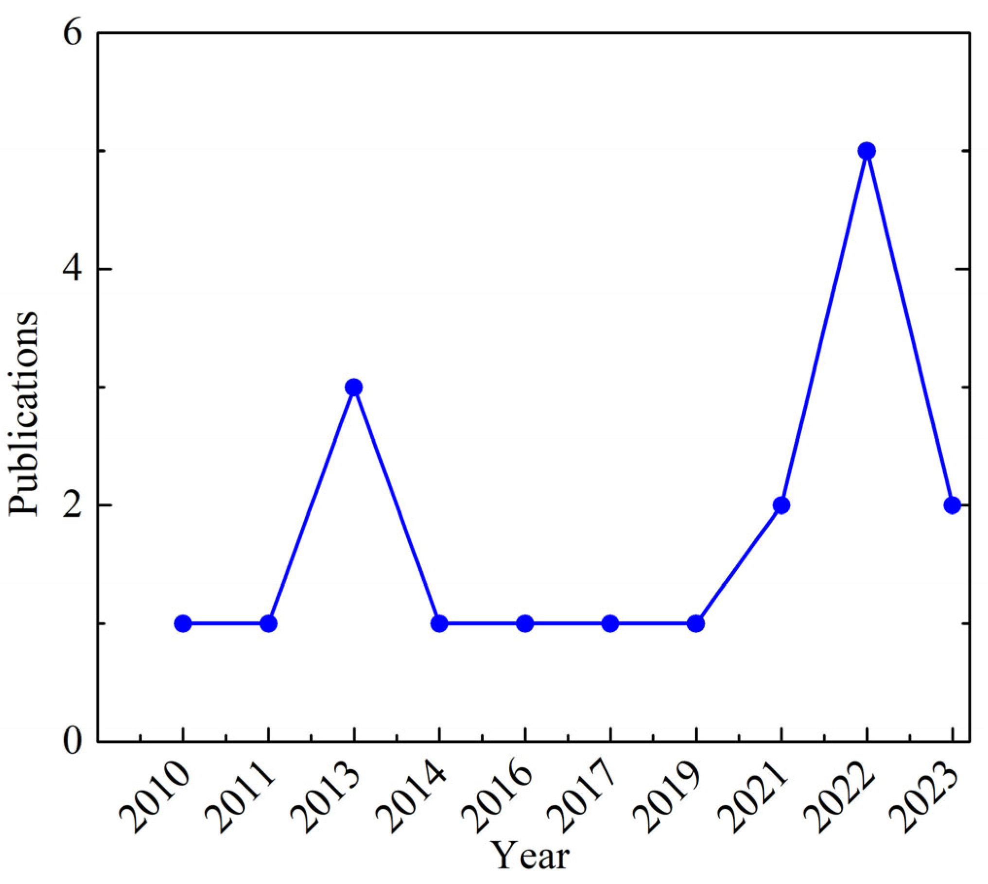
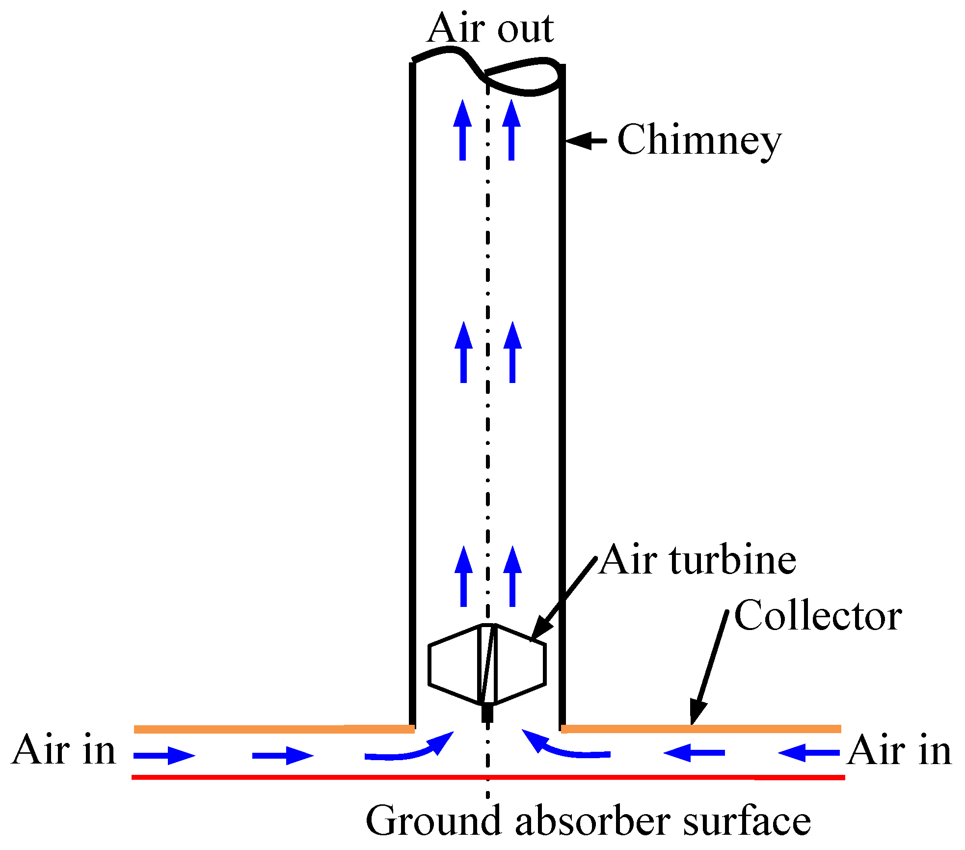
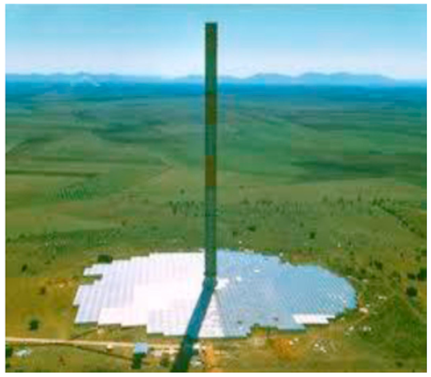
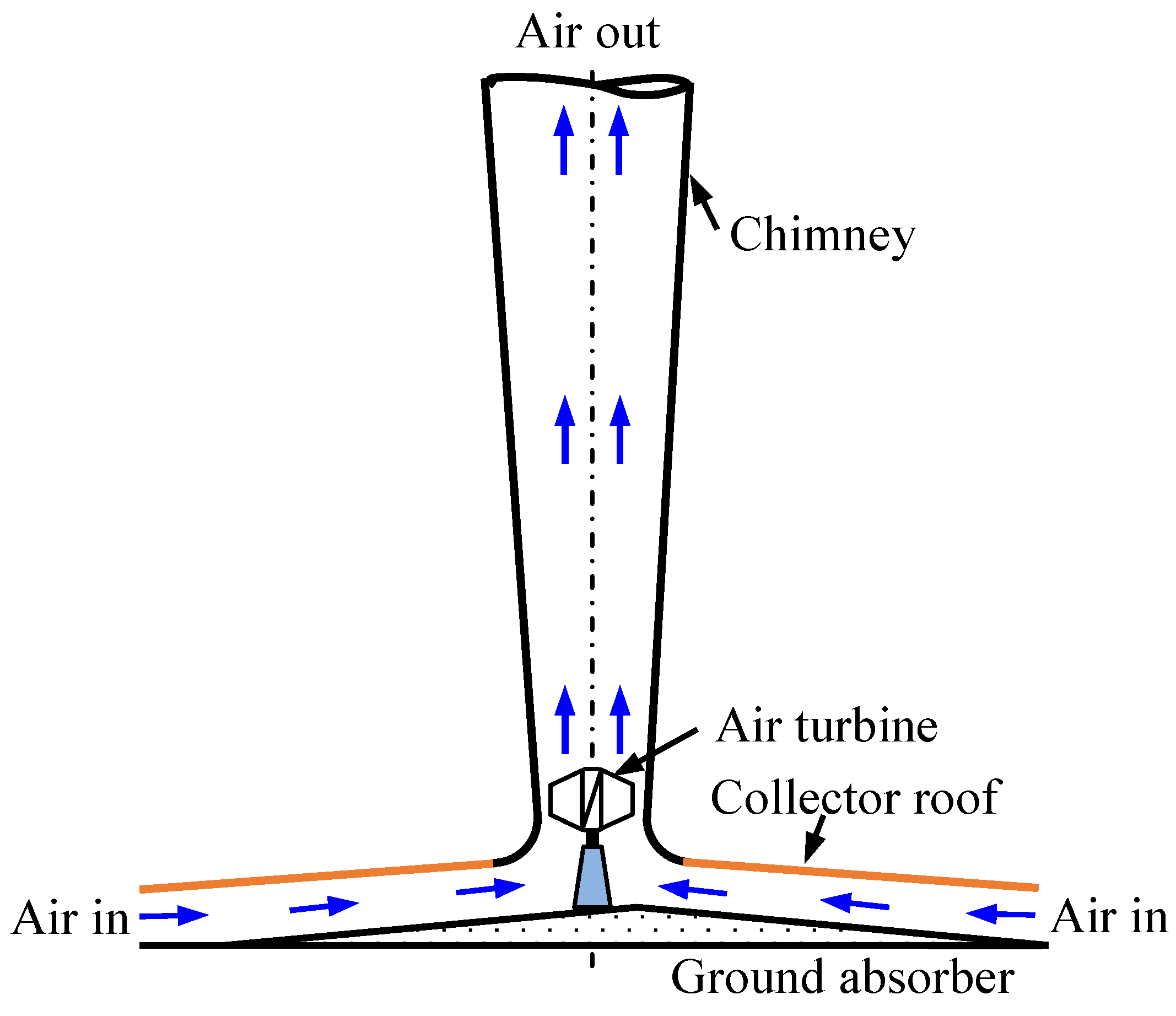
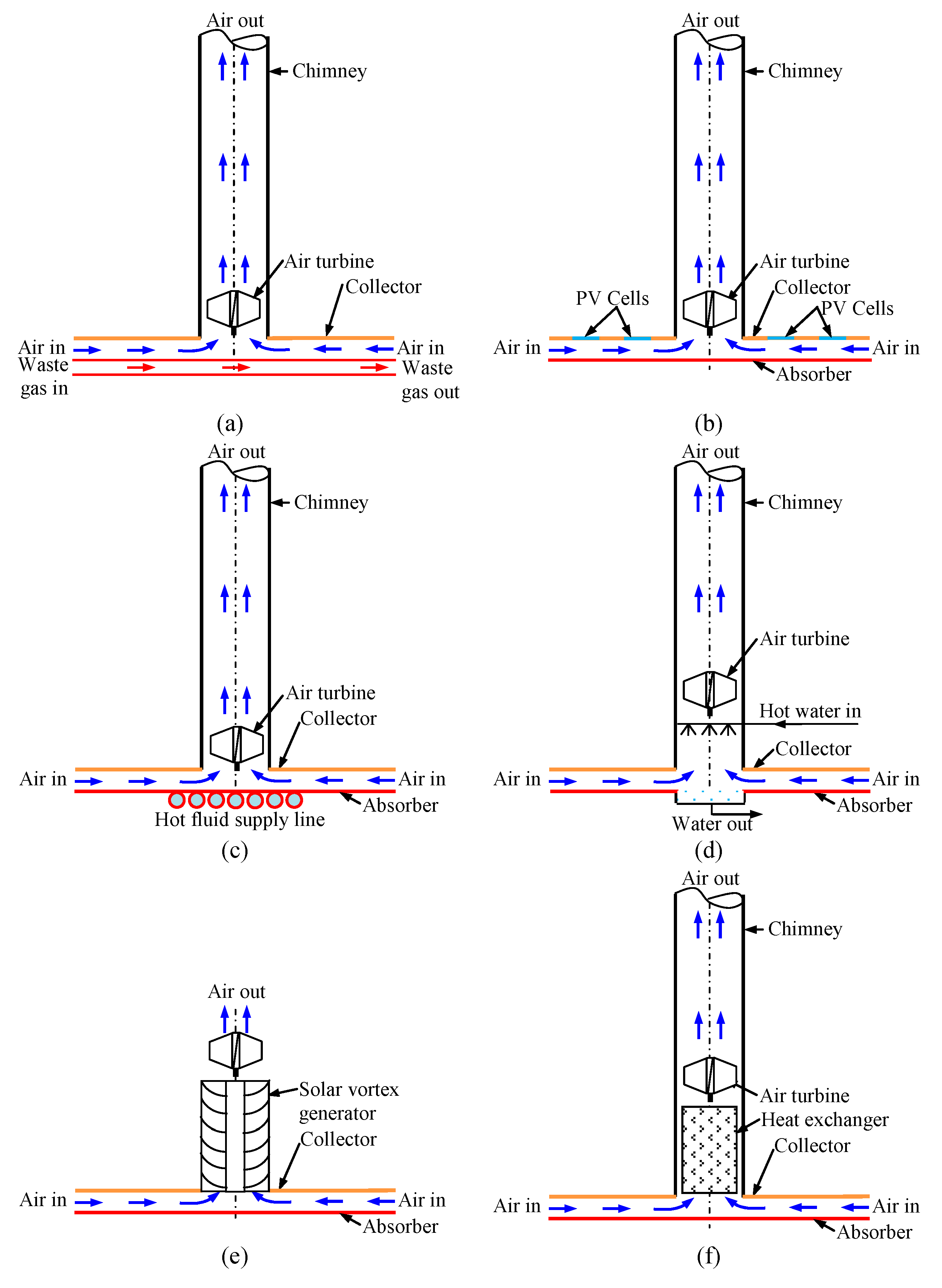
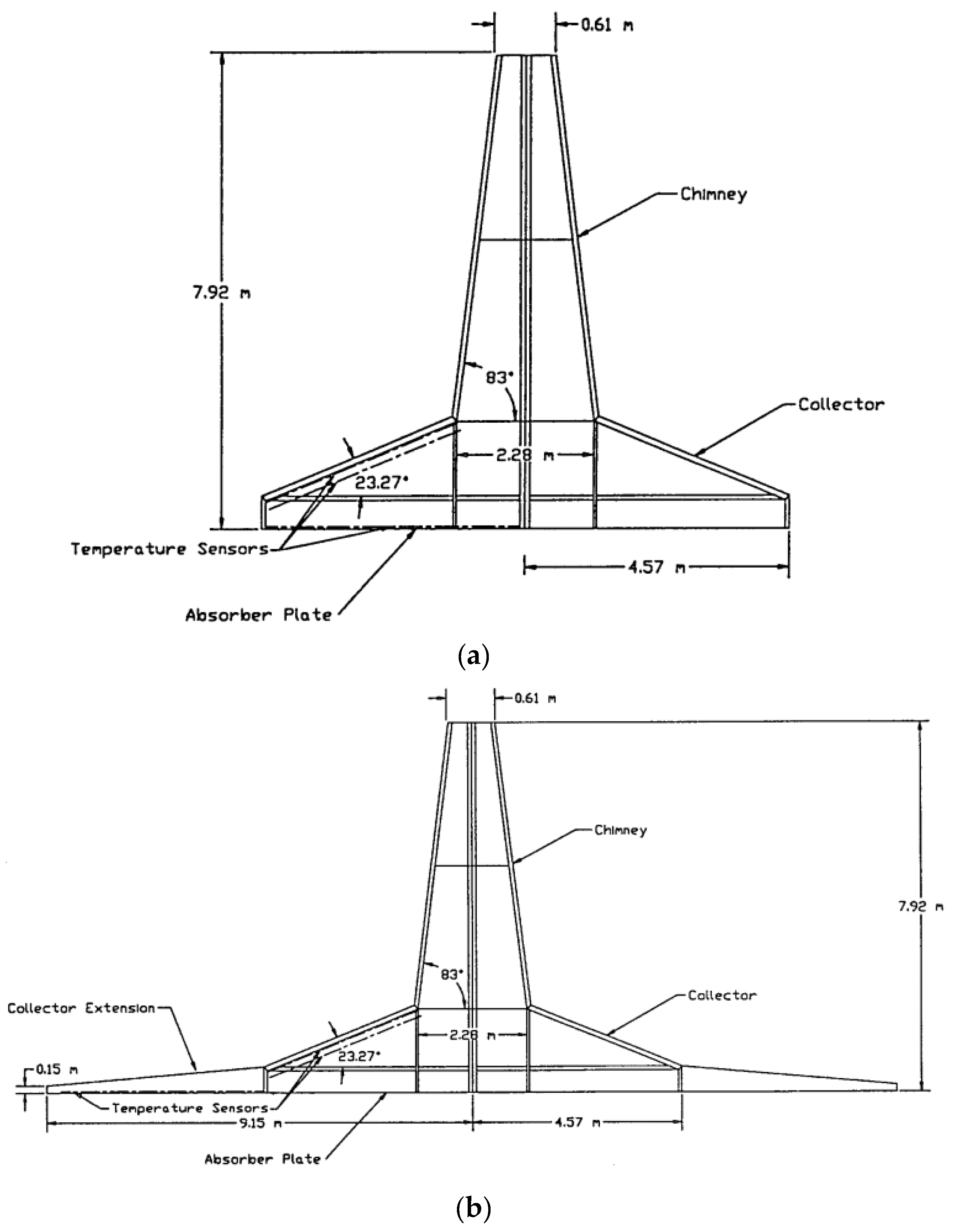
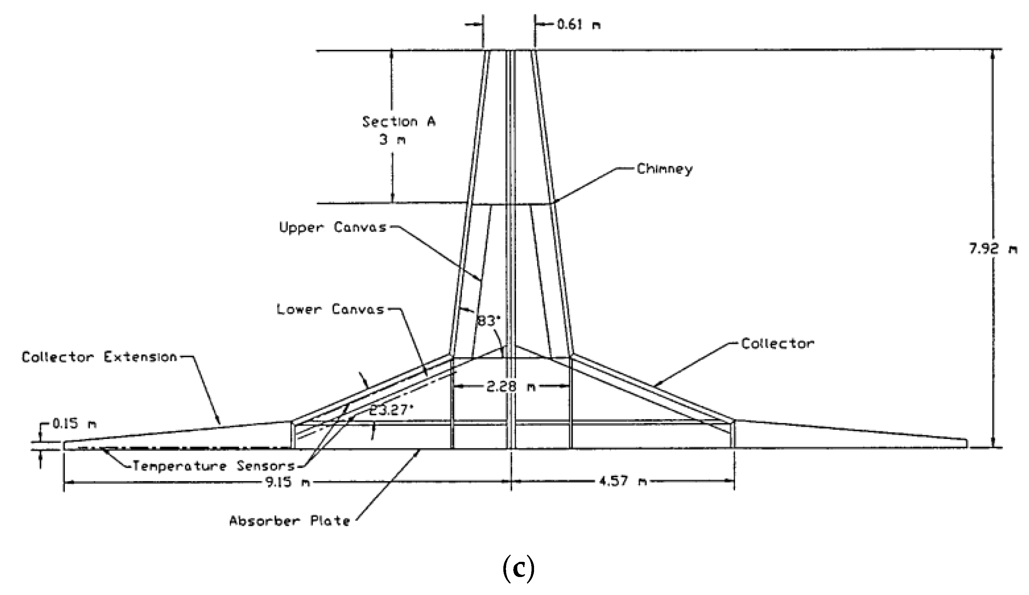
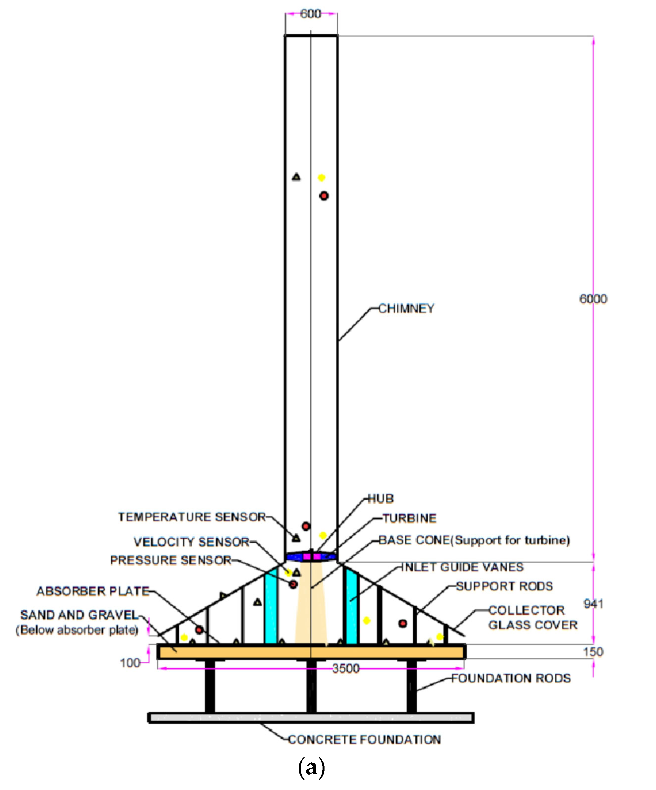
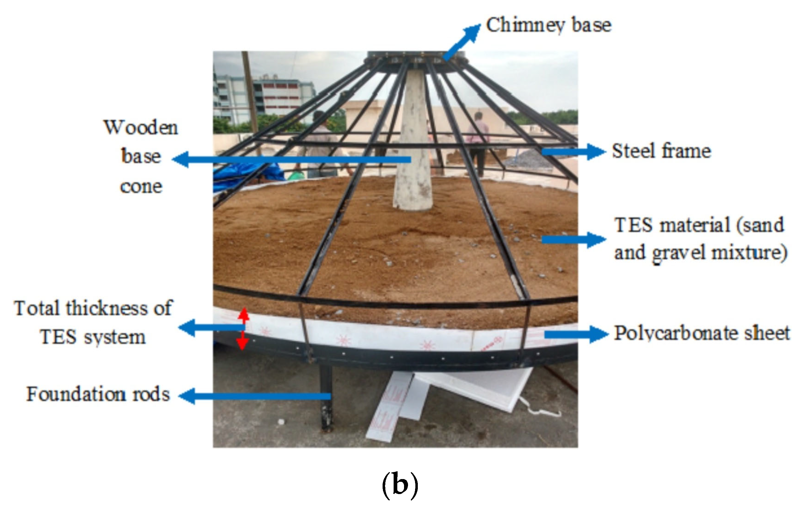
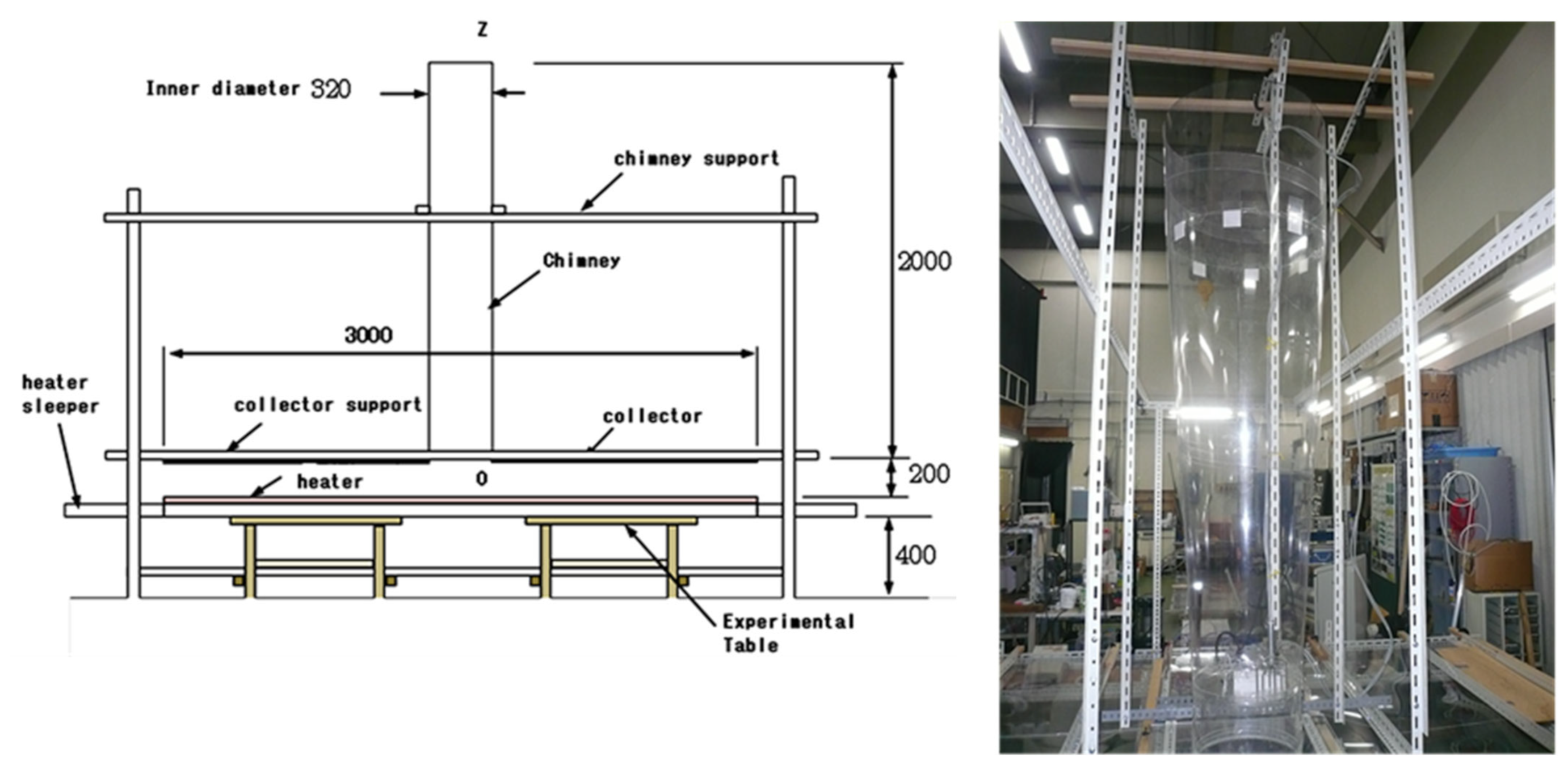


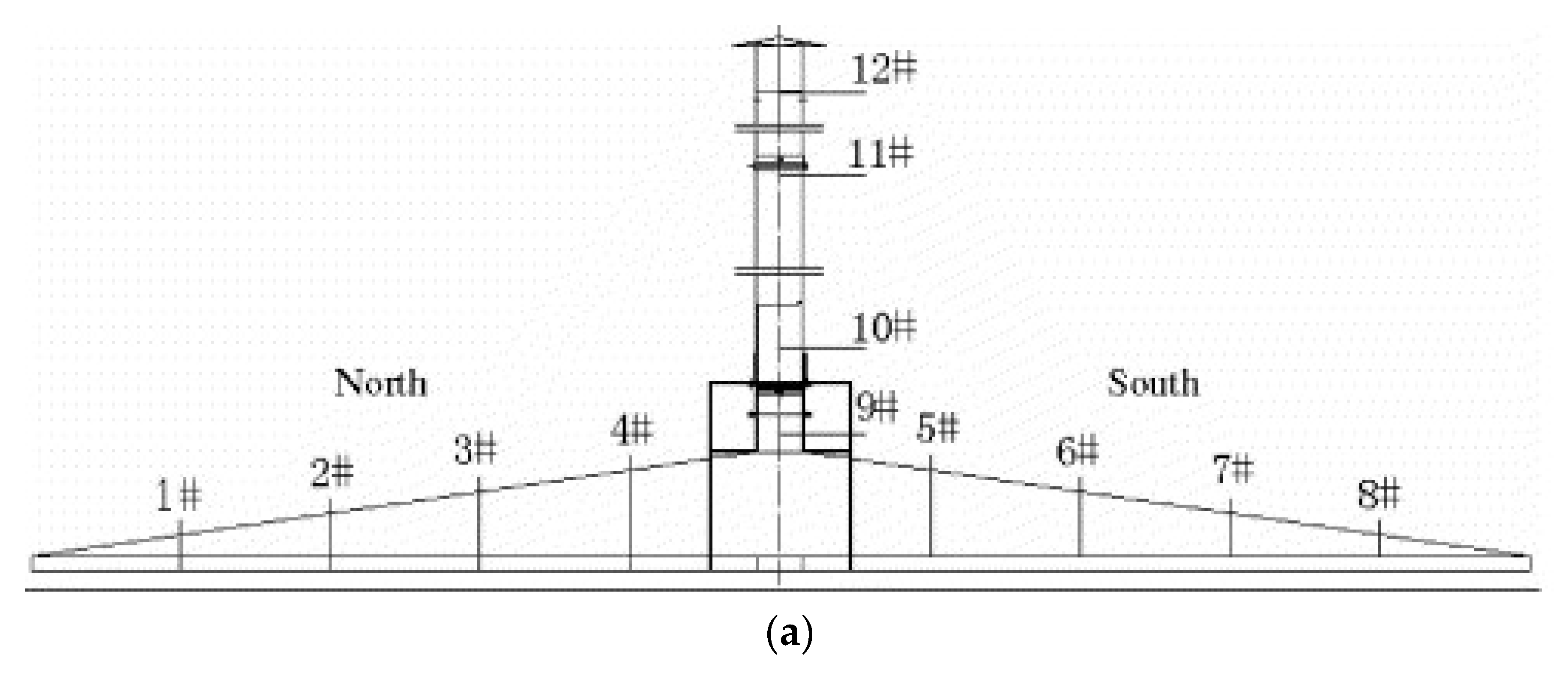
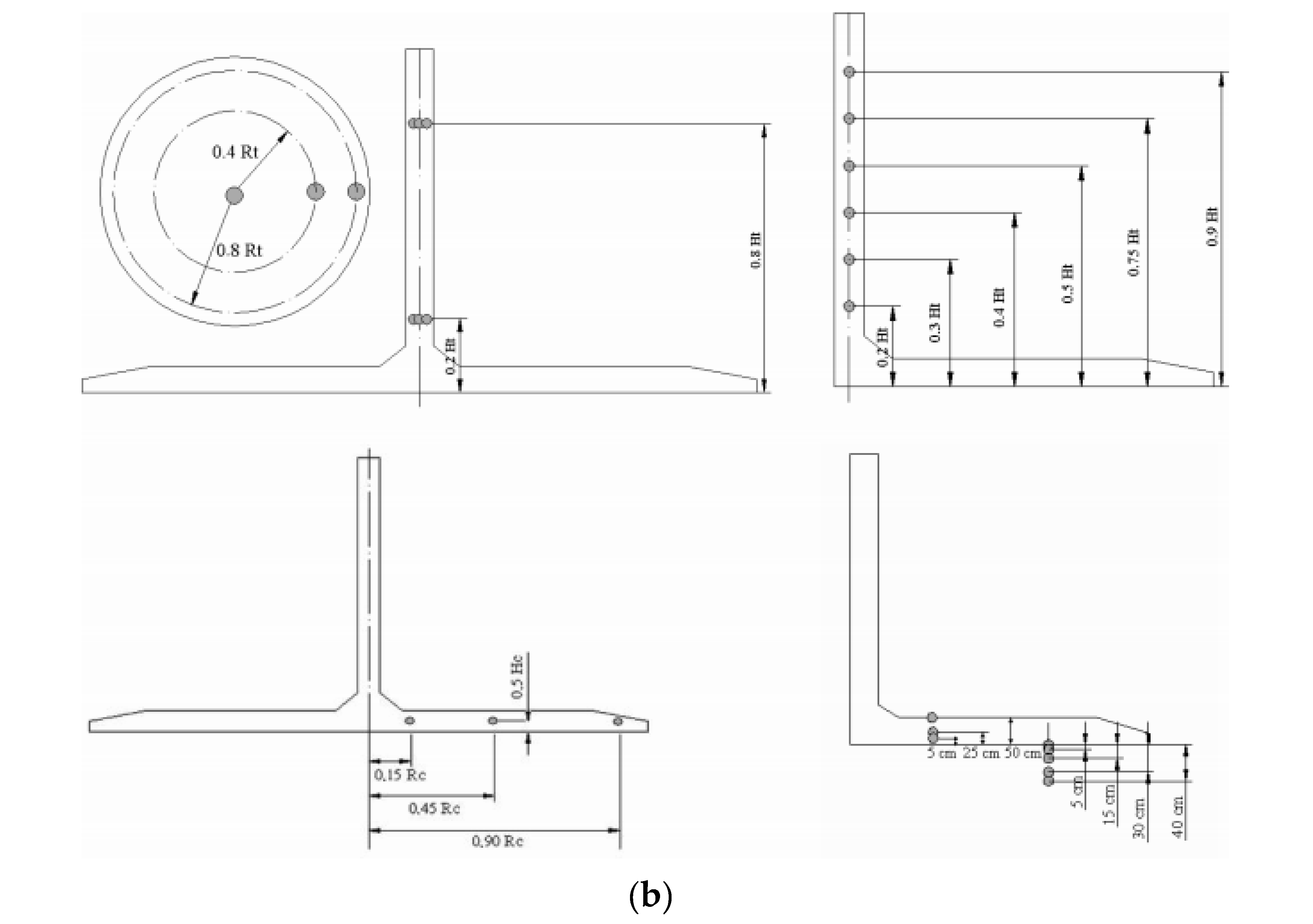
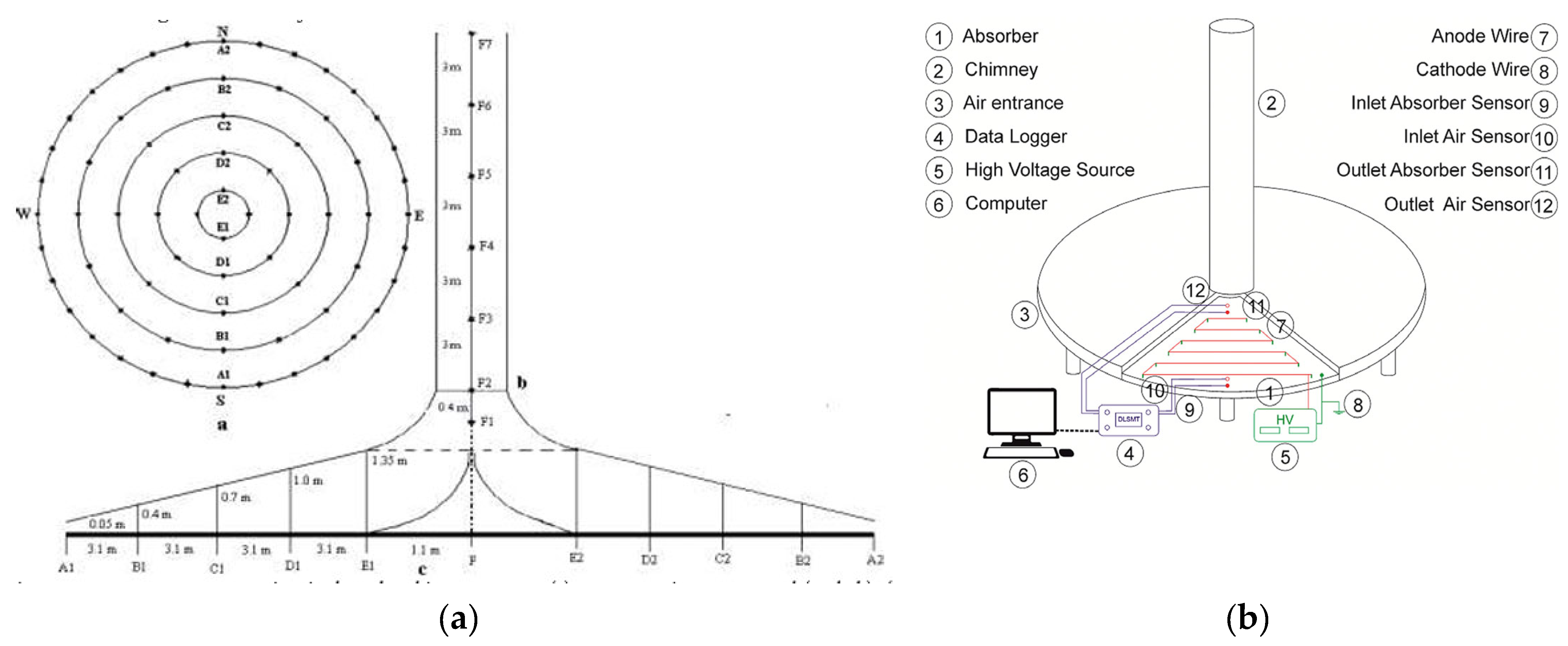
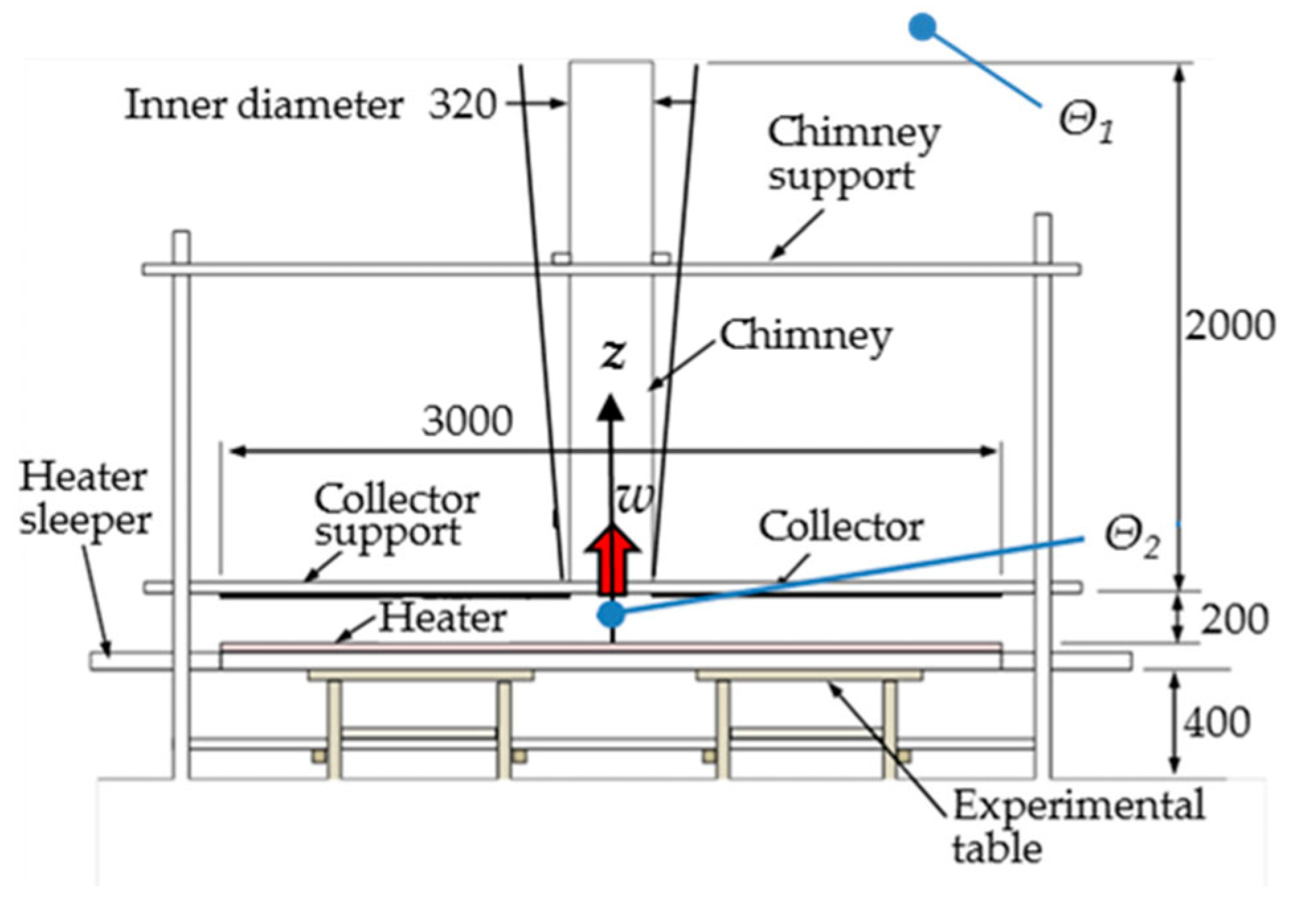
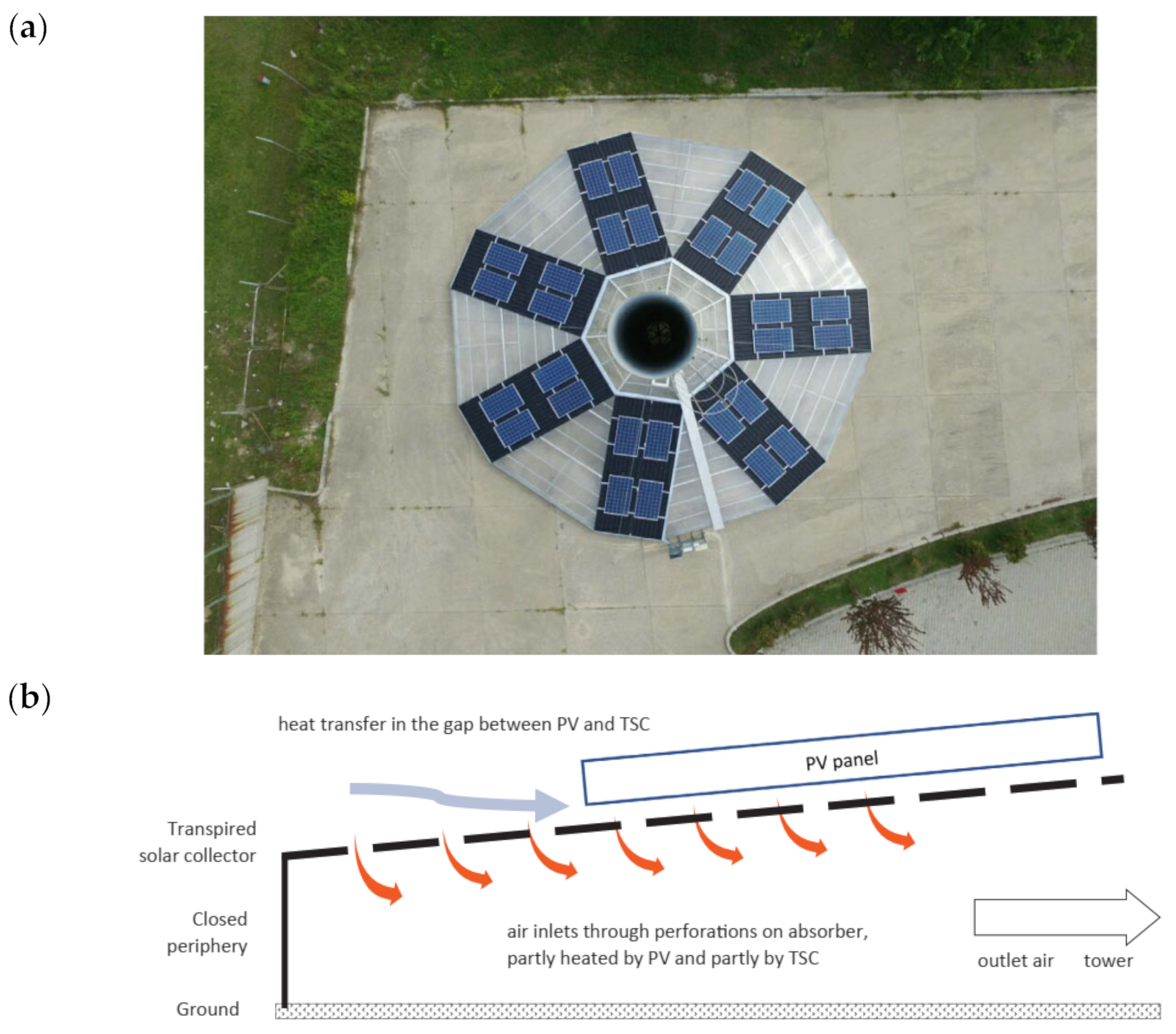

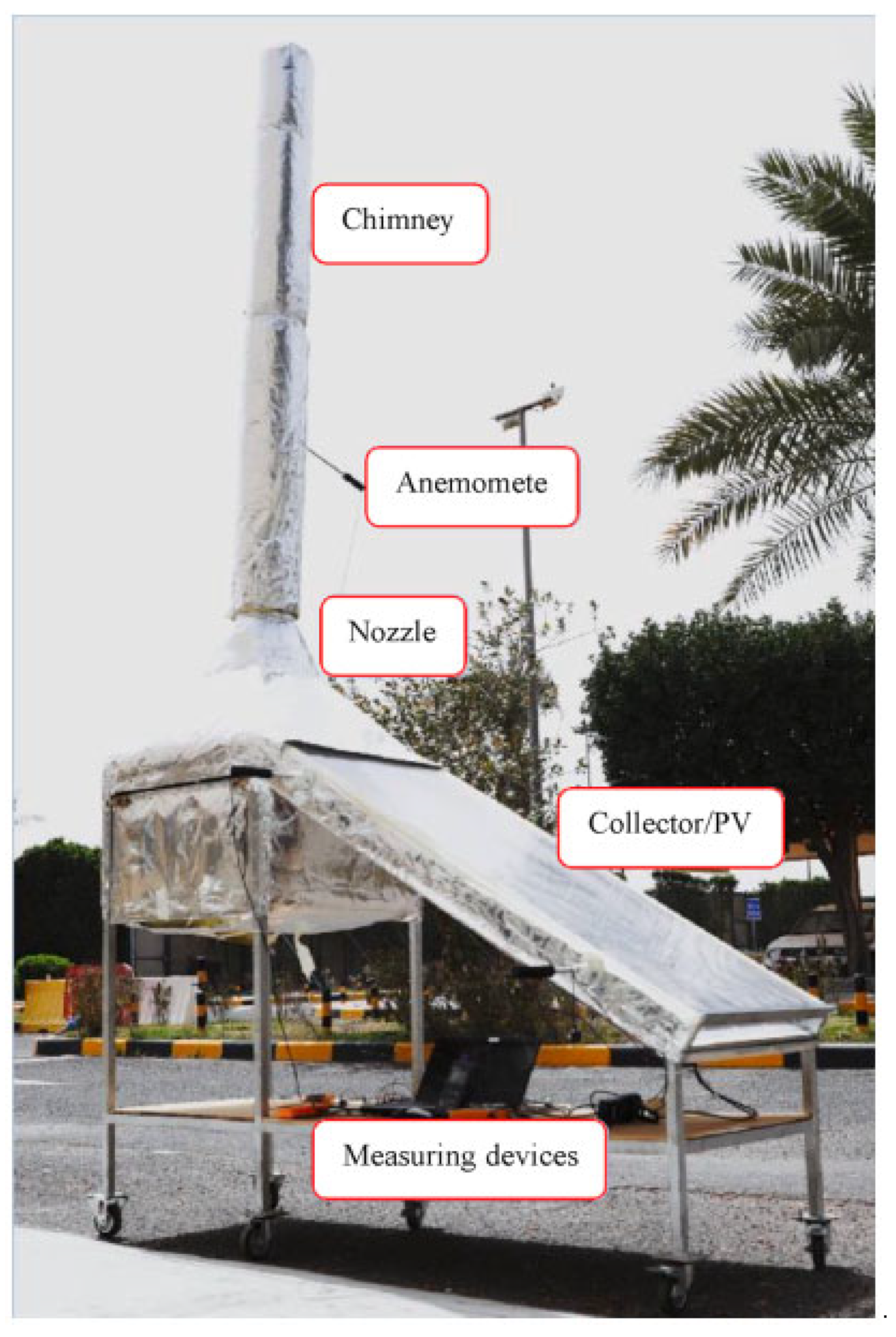


Disclaimer/Publisher’s Note: The statements, opinions and data contained in all publications are solely those of the individual author(s) and contributor(s) and not of MDPI and/or the editor(s). MDPI and/or the editor(s) disclaim responsibility for any injury to people or property resulting from any ideas, methods, instructions or products referred to in the content. |
© 2023 by the authors. Licensee MDPI, Basel, Switzerland. This article is an open access article distributed under the terms and conditions of the Creative Commons Attribution (CC BY) license (https://creativecommons.org/licenses/by/4.0/).