Article

Development of Hybrid Membrane Systems for Highly Mineralized Waste Utilization in the Power Industry

by
Iliya Krastev Iliev
1,
Andrey Alexandrovich Chichirov
2,
Antonina Andreevna Filimonova
2,*,
Natalia Dmitrievna Chichirova
2,
Alexander Vadimovich Pechenkin
2 and
Ivan Hristov Beloev
3
1
Department of Heat, Hydraulics and Environmental Engineering, “Angel Kanchev” University of Ruse, 7017 Ruse, Bulgaria
2
Department “Chemistry and Hydrogen Energy”, Kazan State Power Engineering University, Kazan 420066, Russia
3
Department of Transport, “Angel Kanchev” University of Ruse, 7017 Ruse, Bulgaria
*
Author to whom correspondence should be addressed.
Energies 2023, 16(17), 6166; https://doi.org/10.3390/en16176166
Submission received: 26 July 2023 / Revised: 7 August 2023 / Accepted: 23 August 2023 / Published: 24 August 2023
(This article belongs to the Section J: Thermal Management)

Abstract

:
In the context of limited water resources and the deterioration of natural water bodies’ state, and with the increase in the regulatory requirements for the quality of effluents, assessing the impact of the industrial and energy complex on water bodies is a task of increasingly greater significance to the whole energy sector. “zero discharge” is considered the most effective strategy for creating environmentally friendly thermal power plants. Hybrid reverse osmosis electrodialysis systems make it possible to obtain solutions with a higher concentration of components compared to single electrodialysis treatment, i.e., more efficient separation of brine and pure water. This article proposes experimental and pilot-industrial studies of a hybrid membrane system operation using industrial wastewater for the disposal of liquid waste from an ion-exchange chemical-desalting water treatment plant of a thermal power plant, followed by a calculation of economic efficiency and an analysis of the environmental feasibility of its use. The developed technological scheme offers separate processing of acidic and alkaline waste regeneration solutions using calcium carbonate reagent and desalination on baromembrane and electromembrane units to obtain clean water and dry residue. The hybrid system includes a booster filter press and an evaporator. The hybrid system makes it possible to provide a thermal power plant with a “zero discharge” with a minimum consumption of reagents and electricity, as well as return all wastewater back to the power plant cycle.

1. Introduction

Since the 1880s, scientists in Europe, the USA, China, and Japan have been developing the organization of “low-discharge” and “zero-discharge” technologies for industrial enterprises and energy facilities in the face of the ever-growing challenge to save fresh water. The concept of “zero discharge” appeared in the USA at the beginning of the 20th century and included the technology of evaporation and crystallization of effluent to obtain solid precipitation. Exploratory research in the field of low-waste resource-saving environmentally friendly technologies is still being actively carried out. The most promising and modern are membrane methods, as well as various combinations and progressive developments utilizing them, including wastewater treatment plants operating from alternative energy sources and capable of producing electricity themselves.
Advanced oxidation processes for the removal of organic pollutants from water, in particular photocatalytic processes, have been shown to be effective due to characteristics such as ease of use, low cost, harmlessness, and unreduced decontamination capability [1,2,3]. The photocatalytic process is able to completely mineralize organic pollutants with the formation of harmless molecules using water and air oxygen as chemical compounds [4]. When a semiconductor is irradiated by any light source, electrons are excited and generate valence band holes, where various reactive oxygen species are formed upon contact with water [2,3]. Several international reviews collected materials on the behavior of photocatalysts during the degradation of organic pollutants. The authors of [5] reviewed more than 50 studies where TiO2-based nanocomposites were used in the degradation of various pharmaceutical preparations. The authors of [6] analyzed at least 70 studies in which semiconductors in a suspension medium were evaluated under different conditions (initial concentration, pH, amount of catalyst, temperature, etc.) in order to remove many types of dyes (methyl orange, methyl blue, rhodamine-b, 4-clorophenol, etc.). Another paper reported an evaluation of 48,000 publications on the photocatalytic degradation of dyes under ultraviolet and visible light irradiation, organized according to dye families [7]. The photocatalytic method achieves a high degradation efficiency of dyes, pharmaceutical contaminants, and heavy metals. However, in the wastewater of energy enterprises it is necessary to reduce the concentration of inorganic impurities, since their content often exceeds the maximum permissible concentration.
The energy system is the predominant water consumer among all types of economic activity. A thermal power plant (TPP) with a capacity of 1 GW consumes about 1 billion tons of water per year, a nuclear power plant (NPP) at least 1.6 billion tons of water per year. Between 30 and 90% of the water consumed is returned to surface water sources. Most of all, sulfates and chlorides are present in the pollutant effluents; if the maximum permissible concentrations in wastewater are exceeded, the TPP faces fines. In the system of water use of power facilities, the largest contribution to the total flow of the plant is made by waste from water treatment plants and, in some cases, circulating cooling systems.
Waste management methods of energy facilities are based on the traditional approach, which consists in their neutralization, detoxification, and discharge. The establishment of “zero liquid discharge” (ZLD) technology with 95–98% recovery of feed water can mainly be achieved using membrane and thermal technologies, or a combination of both [8,9,10].
The thermal technologies commonly used to treat reverse osmosis (RO) concentrate are evaporative (flash method, multi-stage evaporation), mechanical (vapor compression technology, thermocompression technology, concentrators, and brine crystallizers) or natural (evaporation ponds) [11].
The main known disadvantage of thermal systems is their energy consumption. One of the possibilities for saving energy in thermal systems is optimizing the operation of various heat exchangers by investigation with computer modeling methods [12]. In addition, powerful thermal power plants (TPPs) discharge more than 500 tons of wastewater every hour. Such streams can be evaporated only by high-performance evaporators, which makes the process thoroughly uneconomical and energy intensive. To level such costs, hybrid systems of water treatment and water purification have been developed. Thus, the combination of membrane and thermal evaporative systems leads to the extraction of feed water up to 99% with more attractive economic indicators than single evaporators [13] (Figure 1). The use of reverse osmosis as the first stage of wastewater treatment with subsequent evaporation minimizes capital and operating costs (about 58–75% of energy and 48–67% of wastewater treatment costs compared to an evaporation plant) [14,15,16].
Hybridization of mechanical thermal systems with reverse osmosis allows about 75–85% of water to be extracted and more than 85% of water in combination with electrodialysis [17,18,19].
Electromembrane technologies have many varieties, represented by the basic technology of electrodialysis and other methods based on electrodialysis—reverse electrodialysis, Donnan electrodialysis, electromembrane extraction, etc. [20]. With the help of electromembrane methods, it is possible to remove water and salt, and also separate the components of a concentrated solution with a high yield of products. Unlike baromembrane methods, the principle of electrodialysis operation is based on the movement of salt ions through the membrane under the influence of an electric current, so that salt is easily separated from water and allows high brine concentrations to be achieved. It is possible to achieve a decrease in the salinity level of the treated solution by more than 10 times (from 3000 ppm to 350 ppm). Under experimental conditions, a brine concentration of 267.6 g/kg was achieved at the cost of about 15 kWh/m3 of electrical energy for electrodialysis [13]. It should be noted that, in comparison with baromembrane methods, the concentration/desalting process proceeds much faster and in one stage, but there are limits to desalting. In addition, electrodialysis can concentrate more than 10% of the total solids in the brine, which cannot be achieved with current reverse osmosis systems. Electrodialysis membranes are less sensitive to pollutants and process conditions, so the requirements for pretreatment of feed water due to possible deposits are lower compared to using reverse osmosis [21,22].
It is considered that electromembrane technologies are more expensive than baromembrane ones. This is due to the low electrical conductivity of dilute solutions. Thus, electrodialysis cannot ensure the complete removal of ions from the solution and has a desalination limit, which affects the efficiency and productivity of the entire process [23]. Baromembrane technologies also require some amount of electricity to drive the pumps. Moreover, the costs increase with a decrease in the size of impurities. Also, a large volume of dilute concentrate produced leads to a low percentage of salt extraction and water recovery [24].
Baromembrane technologies for liquid waste desalination are used both as an independent method and in combination with thermal desalination and other technologies [25].
The use of reverse osmosis as an independent technology for wastewater treatment involves significant difficulties associated with restrictions on the salinity of treated water and membrane fouling [26,27]. Therefore, it is necessary to use pre-treatment, for example, reagent softening, ion-exchange softening, pH adjustment, and other methods that help reduce the deposits on reverse osmosis membranes [28].
In connection with the above-mentioned features of electro- and baromembrane technologies, it was the synergy of electrodialysis, which provides high recovery, and reverse osmosis systems, with the final high purity of the product, that gave rise to the analysis of hybrid electrodialysis–reverse osmosis systems. In practice, the recovery factor of a reverse osmosis plant in a hybrid configuration is a design variable. Increasing the recovery factor results in enhanced reverse osmosis costs associated with a multiplied risk of scale formation due to higher brine concentrations; higher energy costs due to increased osmotic pressure; and the need for a second reverse osmosis stage if recovery above 50% is required [29].
The hybrid system has two advantages compared to a stand-alone electrodialysis system: it is possible to reduce the number of membrane pairs of the electrodialyzer since the reverse osmosis concentrate is supplied to it as a nutrient solution; therefore, the salt removal rates (current density) become higher; the requirements for the electrodialysis product are relaxed since the final product consists of a high purity mixture reverse osmosis permeate and the electrodialysis product.
Comparing electrodialysis systems operating in stand-alone and hybrid configurations, it can be concluded that the cost of desalination of the electrodialysis product is always higher for a stand-alone system since the degree of product purification is completely dependent on the operation of the electrodialyzer. Study [30] compared various configurations of membrane systems for desalination and concentration of effluents: a standard single-stage reverse osmosis (RO) system, a hybrid reverse osmosis–electrodialysis (RO-ED) system, a nanofiltration–reverse osmosis (NF-RO) system, and a nanofiltration–reverse osmosis–electrodialysis (NF-RO-ED) system. Indicators such as the percentage of diluate and concentrate yield, the total salt content of the concentrate (TSC), the energy expended, the risk of scale formation, and the possibility of reusing products were evaluated (Table 1).
The most effective was the NF-RO-ED system, which is capable of producing a highly concentrated brine close to saturation with respect to sodium chloride and the largest volume of diluate. The brine can be further used in the production of table salt or in the chlorine industry. In the case of one-stage RO, for every 1 m3 of demineralized water, 0.574 m3 of concentrate (OSC 60 g/L) is produced, which must be disposed of, which creates additional costs. The integration of NF and RO does not significantly change the salinity and volume of the resulting brine compared to the RO configuration. The introduction of ED helps to solve the problem of a large volume of low-mineralized waste. The NF-RO-ED system produces less clean water than the RO-ED configuration but produces a more concentrated brine. In the NF-RO-ED system, NF removes most of the divalent hardness ions from the RO-ED circuit. Due to the reduced risk of scale formation in the ED module, recirculation occurs on the concentrate side, resulting in a concentrate that is practically saturated with sodium chloride [31].
In 2018, industrial plants were tested in Brazil, consisting of series-connected reversible ED-RO (version 1, Figure 2) or RO-reversible ED (version 2, Figure 3) devices for petrochemical wastewater treatment in order to obtain process water for reuse.
The hybrid system of reverse ED-RO (Figure 2) showed the degree of removal of more than 98% of impurities from wastewater. The results obtained meet the quality requirements for reuse in cooling towers. Through reverse ED, 75% water recovery was achieved, while 50% was recovered by RO, so that the hybrid process provided an average 41% of the total water recovery [32].
In the case of changing the order of conducting ED and RO according to the second option [33] (Figure 3), the volume of recovered diluate significantly increased (87.3%). The degree of impurity removal was more than 75%. This percentage turned out to be less than in the first version of the ED-RO but nevertheless met the standards for using diluate as cooling circulating water.
An example of boiler make-up water treatment and wastewater disposal at TPPs with “zero” discharge is the installation of the company “Doswell Limited Partnership”. The source water is preliminarily desalinated at a six-stage reverse osmosis unit, degassed in a deaerator and additionally desalted at a chemical desalination unit. Reverse osmosis brine, chemical desalination plant concentrate, and boiler blowdown water after a mechanical filter enter the electrodialysis unit, and then into the reverse osmosis unit. The concentrate from the installations is evaporated in the evaporator–crystallizer and then dehydrated in a filter press [34].
Despite the large number of proposed theoretical computational and modeling studies of hybrid systems, wastewater treatment technologies for real industrial facilities and energy enterprises are presented in insufficient quantities [35]. There is also insufficient information on the economic and environmental efficiency of hybrid technologies for the industrial and energy sector. Thus, one study compares a hybrid electrodialysis–reverse osmosis system with a reverse osmosis–mechanical vapor compression system, concluding that hybrid membrane technologies have lower initial capital costs and lower operating costs [36]. In another study, it was shown that the use of hybrid electro-biomembrane systems for wastewater treatment is justified only if the cost of reverse osmosis is less than 40% of an electrodialysis system cost [37].
Thus, additional experimental and pilot-industrial studies of the hybrid membrane plant operation using both model solutions and industrial wastewater are required, followed by a calculation of economic efficiency and an analysis of the environmental feasibility of their use.

2. Materials and Methods
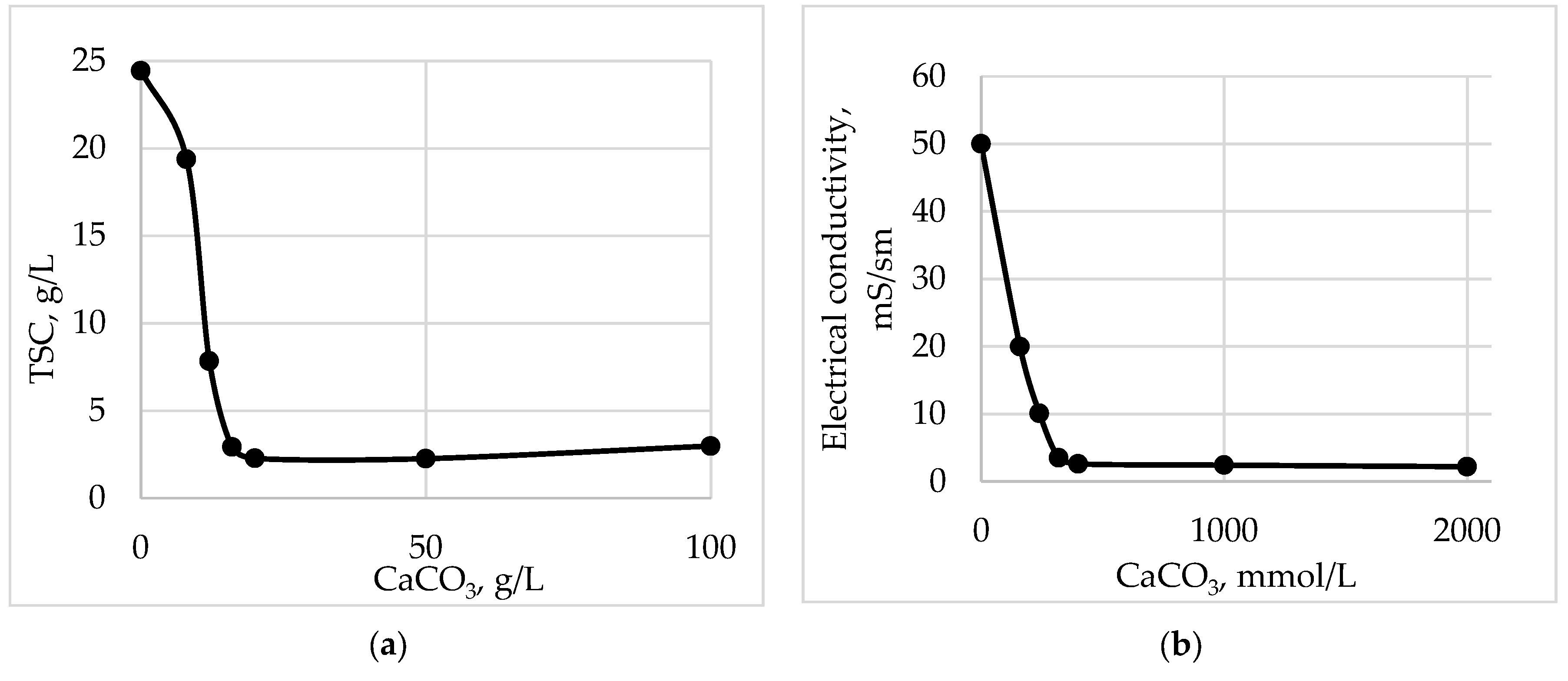
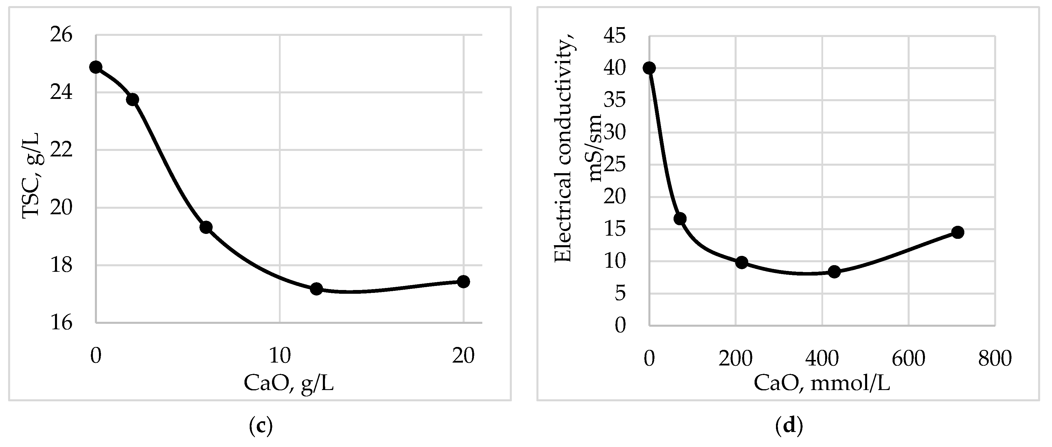
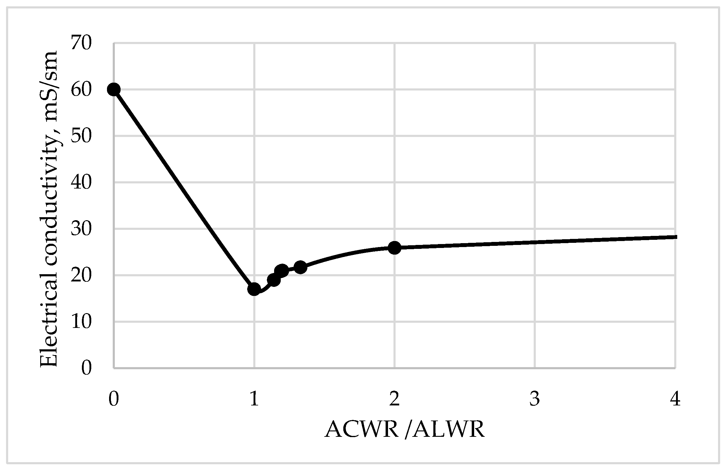
Experimental studies on utilization at a hybrid baro-electro membrane system were carried out on acidic (ACWR) and alkaline (ALWR) waste regeneration solutions of an ion-exchange chemical-desalting water treatment plant (WTP) of a thermal power plant (Table 2). Technical characteristics of the electromembrane and baromembrane installations are given in Table 3 and Table 4.
The electromembrane apparatus used commercially available industrial heterogeneous ion-selective cation- and anion-exchange membranes IONSEP, which are a highly filled polymer composite consisting of finely ground polymer particles with ion-exchange functional groups fixed in the internal polymer matrix and a reinforcing fabric that improves the mechanical properties of the membrane. Passport characteristics of the used ion-exchange membranes are presented in Table 5.
The analysis of solutions was carried out for hydrate alkalinity and carbonate alkalinity, total hardness, sulfates, color by spectrophotometric method, pH, and electrical conductivity according to known methods of analysis. The total salt content was calculated from the calibration curve from the electrical conductivity data.
According to the initial conditions of the experiment, in the line of dialysate and concentrate of the electrodialysis apparatus, there were 10 dm3 of solution with a temperature of 25 °C. The volumetric circulation rate of working solutions was 300 dm3/h. The voltage supplied to the device was 75 V.

3. Results

To develop the technology of wastewater treatment by combined membrane methods, a technological scheme was created, including reverse osmosis, electrodialysis, filter press, and an evaporator unit (Figure 4).
Acidic and alkaline waste regeneration solutions are treated separately in the hybrid plant before being discharged. A well-known problem of effluents from an ion-exchange water treatment plant is the large amount of acidic, highly mineralized effluents with high hardness and exceeding the allowable concentration limit for sulfates, for which TPPs pay heavy fines. According to the proposed technological scheme, the waste of an ion-exchange water treatment plant is proposed to be processed as follows:
-
ACWR with a high content of hardness ions and sulfates is subjected to preliminary liming and dehydration in a filter press to precipitate gypsum;
-
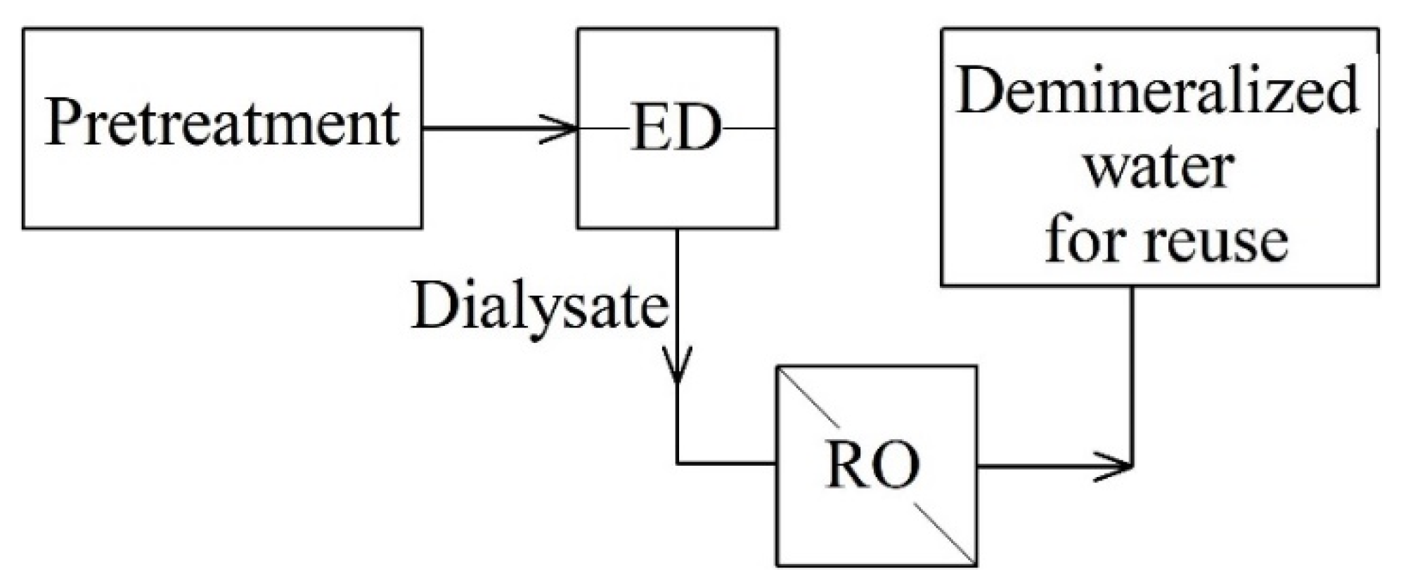
ALWR is sent for electrodialysis if the electrical conductivity is less than 40 mS/cm for separation into a contaminated concentrate and a purified dialysate;
-
If the electrical conductivity of ALWR is more than 40 mS/cm, then it is mixed in a neutralizer tank with limed ACWR;
-
The concentrate after electrodialysis is sent to the neutralization tank for mixing with limed ACWR and the purified dialysate is sent as the source water of the ion-exchange water treatment plant;
-
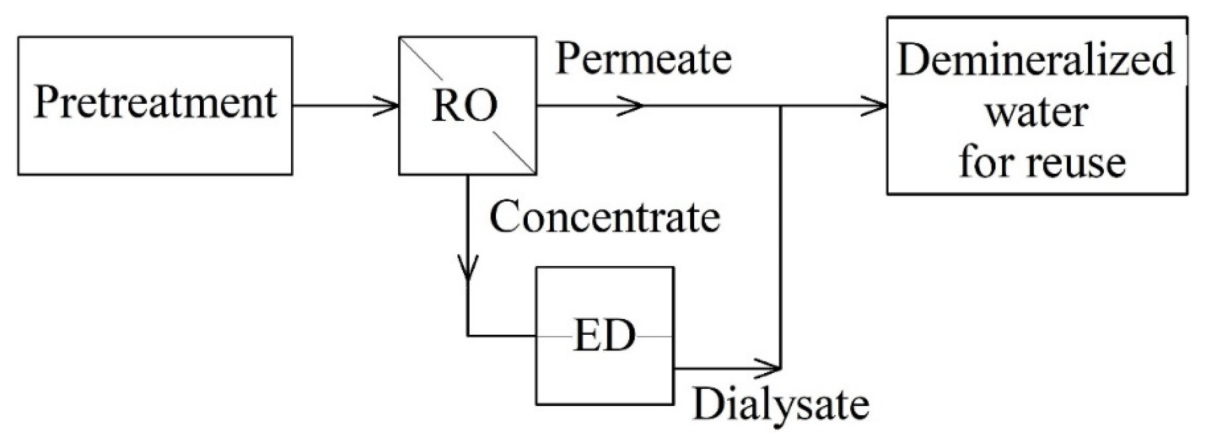
After the neutralizer tank, the neutralized concentrated acidic and alkaline WRs pass sequentially through a mechanical and carbon filter, and then baromembrane system—nanofiltration and reverse osmosis;
-
The concentrate of the baromembrane plant, which is mainly sodium salts, can be reused for the regeneration of Na-cation exchange filters, or evaporated to obtain a distillate and a dry residue, and the reverse osmosis permeate is sent to the water treatment plant as source water.
CaO, CaCO3, and alkaline WR were used to treat acidic WR. Figure 5 shows that, when calcium carbonate is used, the content of sulfates in acid waste is reduced by a factor of 20 or more than 90%. When dosing quicklime, the decrease in sulfates is only 1.5 times.
When dosing calcium carbonate, the electrical conductivity and total salt content are also significantly reduced in comparison with the dosing of quicklime (Figure 6). Thus, the total salt content is reduced by 91% and the specific electrical conductivity by 95%.
When ACWR is neutralized with ALWR, a small amount of precipitate is formed (Figure 7). This is characterized by a dip in the curve on the graph; then, the electrical conductivity of the solution begins to increase.
The obtained results of the experimental data indicate the need for reagent treatment of the acidic regeneration solution before mixing it with an alkaline regeneration solution, and not after, as is traditionally carried out at thermal power plants. After mixing, the neutralized acidic and alkaline WR are sent to the baromembrane unit according to the proposed technological scheme (Table 6).
After liming of acidic regeneration solutions, mutual neutralization, and a baromembrane purification, sulfates, hardness, electrical conductivity, color, and organic molecules in the permeate are reduced. To reduce sedimentation on the membranes, the reverse osmosis unit must be periodically flushed with acid solutions. The concentrate is sent to the evaporation plant to obtain a distillate in the amount of 6 L and a dry residue. Another variation allows foregoing the usage of an evaporative unit. According to this variation, concentrate from the baromembrane plant, which comprises mainly sodium salts, can be reused for the regeneration of Na-cation exchange filters. The reverse osmosis permeate is reused in the water treatment plant as source water. Thus, a complete processing of highly concentrated effluents from the ion-exchange water treatment plant of TPP with “zero discharge” of liquid waste is carried out.
In case of discharge of low-concentrated alkaline waste regeneration solutions (electrical conductivity < 40 mS/cm), they must first be concentrated in an electrodialysis unit (Table 7).
The electrodialysis concentrate is then sent for mixing with the limed acidic regeneration solutions and the dialysate is returned to the water treatment plant as raw water.
Calculations were made of the returned water cost for various recycling schemes.
Based on the calculations of the membrane characteristics from different manufacturers, the average power consumption for transferring 1 kg is 1.4 kWh/kg of salt. The total power consumption for electromembrane separation of 300 l/h and the production of 20.15 g of salt per 1 dm3, taking into account the costs of preliminary pumping of solutions through the apparatus, is 915.2 Wh. Thus, the cost of operating the electrodialysis part of the plant will be EUR 0.013 per 100 dm3 of wastewater.
Energy costs for reverse osmosis are on average 55.5 kWh/m3. Thus, the cost of processing 100 dm3 of wastewater will be EUR 0.22.
According to the experimental data obtained, calcium carbonate showed better results in reducing the content of sulfates in acidic effluents than quicklime. The cost of calcium carbonate is EUR 0.02 per kilogram. The cost of sulphate reduction is EUR 0.032 per 100 dm3 of waste.
The proposed technological scheme allows all the water from wastewater to be returned for reuse. The cost of returned water is EUR 0.10 per 1 m3.
Thus, the total cost of wastewater treatment of the ion-exchange chemical desalination plant at the TPP will be EUR 2.6 per 1 m3.

4. Discussion

Energy enterprises are characterized by excessive consumption of resources (water, reagents) to ensure the production of heat and electricity. The initially deposited surplus eventually forms the bulk of industrial wastewater. Therefore, the implementation of resource-saving technologies will lead to a decrease in highly mineralized effluents and thus a decrease in the environmental burden on the region.
A solution to the discharge problem is offered by the extraction of valuable components and their reuse in the water cycle of the industrial and energy complex. These solutions can be successful provided concentrated liquid waste is disposed of directly from the technical water circulation facilities of the energy facility by a certain method. There is a further dependence on the composition and type of wastewater discharged from the facility and the desired effect from its processing. Subsequent operations of mixing (mutual neutralization) of liquid waste and dilution lead to the transformation of complex compositions into wastewater, the processing of which is not economically feasible.
Table 8 presents both traditional and modern high-tech wastewater treatment methods used. A comparison of monocomponent technologies with hybrid systems is presented.
Combined methods provide not only a synergistic effect for a particular industrial separation but also an optimization of the materials, energy, and space used. In this sense, integration is a practical strategy for sustainable industrial growth that the energy industry and industry in general are facing today.

5. Conclusions

A technological scheme of a hybrid membrane system was developed for the disposal of highly mineralized waste from an ion-exchange chemical-desalting water treatment plant to implement the principle of resource-saving when creating thermal power plants with “zero discharge”. The hybrid system uses baromembrane and electromembrane technologies. If necessary, a reagent treatment, a filter press, and an evaporator unit are added. Waste from the water treatment plant is proposed to be treated separately, using data on the composition of the treated waste, prior to pre-mixing and neutralization according to the principle of separate waste collection. The result of membrane treatment is the production of partially or completely demineralized water, which can be reused in the technological cycle of an energy facility and as a dehydrated residue. The total working cost of the proposed technological scheme with a hybrid membrane system will be EUR 2.6 per 1 m3.
The ecological impact of the implementation of the proposed resource-saving technologies would be demonstrated by the following: reduction of natural water intake for the energy system needs; reducing the discharge of highly mineralized polluted wastewater; reducing the salinity of rivers and soil, which has a positive effect on the yield and quality of drinking water; a minimization or complete rejection of toxic chemical reagent use and their replacement with neutral, naturally occurring substances; and returning to the production cycle or reducing the consumption of chemical reagents through the usage of modern water treatment methods.

Author Contributions

A.A.C. and A.V.P. worked on all the tasks, A.A.F. and N.D.C. worked on the literature review, A.V.P. and A.A.F. conducted experimental studies, I.K.I. and I.H.B. performed the supervision, all authors analyzed the results. All authors have read and agreed to the published version of the manuscript.

Funding

The study was funded by Russian Science Foundation grant No. 22-29-01300, https://rscf.ru/en/project/22-29-01300/. This work has been accomplished with the financial support from Grant No BG05M2OP001-1.002-0011-C02 financed by the Science and Education for Smart Growth Operational Program (2014-2020) and co-financed by the European Union through the European Structural and Investment funds.

Data Availability Statement

All data can be used on request.

Conflicts of Interest

The authors declare no conflict of interest.

Nomenclature

EDelectrodialysis
ROreverse osmosis
ZLDzero liquid discharge
NFnanofiltration
TPPsthermal power plants
ACWRacidic waste regeneration solutions
ALWRalkaline waste regeneration solutions
WTPwater treatment plant
TSCtotal salt content

References

  1. Zhang, L.; Ma, P.; Dai, L.; Li, S.; Yu, W.; Guan, J. In situ crystallization and growth of TiO2 nanospheres between MXene layers for improved adsorption and visible light photocatalysis. Catal. Sci. Technol. 2021, 11, 3834–3844. [Google Scholar] [CrossRef]
  2. Garrido-Cardenas, J.A.; Esteban-García, B.; Agüera, A.; Sánchez-Pérez, J.A.; ManzanoAgugliaro, F. Wastewater treatment by advanced oxidation process and their worldwide research trends. Int. J. Environ. Res. Public Health 2020, 17, 170. [Google Scholar] [CrossRef]
  3. Zhu, D.; Zhou, Q. Action and mechanism of semiconductor photocatalysis on degradation of organic pollutants in water treatment: A review. Environ. Nanotechnol. Monit. Manag. 2019, 12, 100255. [Google Scholar] [CrossRef]
  4. Babu, S.G.; Karthik, P.; John, M.C.; Lakhera, S.K.; Ashokkumar, M.; Khim, J.; Neppolian, B. Synergistic effect of sono-photocatalytic process for the degradation of organic pollutants using CuO-TiO2/rGO. Ultrason. Sonochem. 2019, 50, 218–223. [Google Scholar] [CrossRef]
  5. Khasawneh, O.F.S.; Palaniandy, P. Photocatalytic degradation of pharmaceuticals using TiO2 based nanocomposite catalyst-review. Civ. Environ. Eng. Rep. 2019, 29, 1–33. [Google Scholar] [CrossRef]
  6. Ahmed, S.; Rasul, M.; Martens, W.N.; Brown, R.; Hashib, M. Advances in heterogeneous photocatalytic degradation of phenols and dyes in wastewater: A review. Water Air Soil Pollut. 2011, 215, 3–29. [Google Scholar] [CrossRef]
  7. Rochkind, M.; Pasternak, S.; Paz, Y. Using dyes for evaluating photocatalytic properties: A critical review. Molecules 2015, 20, 88–110. [Google Scholar] [CrossRef]
  8. McGovern, R.K.; Zubair, S.M.; Lienhard, J.H. Hybrid electrodialysis reverse osmosis system design and its optimization for treatment of highly saline brines. IDA J. Desalination Water Reuse 2014, 6, 15–23. [Google Scholar] [CrossRef]
  9. Li, W.; Krantz, W.B.; Cornelissen, E.R.; Post, J.W.; Verliefde, A.R.D.; Tang, C.Y. A novel hybrid process of reverse electrodialysis and reverse osmosis for low energy seawater desalination and brine management. Appl. Energy 2013, 104, 592–602. [Google Scholar] [CrossRef]
  10. McGovern, R.K.; Zubair, S.M.; Lienhard, V.J.H. The benefits of hybridising electrodialysis with reverse osmosis. J. Membr. Sci. 2014, 469, 326–335. [Google Scholar] [CrossRef]
  11. Al-Anzi, B.S.; Al-Rashidi, A.; Litty, A.; Fernandes, J.; Al-Sheikh, A.; Alhazza, A. Brine management from desalination plants for salt production utilizing high current density electrodialysis-evaporator hybrid system: A case study in Kuwait. Desalination 2021, 498, 114760. [Google Scholar] [CrossRef]
  12. Kolev, Z.D.; Kadirova, S.Y. Numerical Modelling of Heat Transfer in Convector’s Pipes by ABAQUS. IOP Conf. Ser. Mater. Sci. Eng. 2019, 595, 012006. [Google Scholar] [CrossRef]
  13. Havelka, J.; Fárová, H.; Jiříček, T.; Kotala, T.; Kroupa, J. Electrodialysis-based zero liquid discharge in industrial wastewater treatment. Water Sci. Technol. 2019, 79, 1580–1586. [Google Scholar] [CrossRef]
  14. Johannsen, P.; Karlapudi, R.; Reinhold, G. High pressure reverse osmosis for wastewater minimization and zero liquid discharge applications. Desalination 2006, 199, 84–85. [Google Scholar] [CrossRef]
  15. Neilly, A.; Jegatheesan, V.; Shu, L. Evaluating the potential for zero discharge from reverse osmosis desalination using integrated processes—A review. Desalination Water Treat. 2009, 11, 58–65. [Google Scholar] [CrossRef]
  16. Yaqub, M.; Lee, W. Zero-liquid discharge (ZLD) technology for resource recovery from wastewater: A review. Sci. Total Environ. 2019, 681, 551–563. [Google Scholar] [CrossRef] [PubMed]
  17. Walker, W.S.; Kim, Y.; Lawler, D.F. Treatment of model inland brackish groundwater reverse osmosis concentrate with electrodialysis—Part I: Sensitivity to superficial velocity. Desalination 2014, 344, 152–162. [Google Scholar] [CrossRef]
  18. Walker, W.S.; Kim, Y.; Lawler, D.F. Treatment of model inland brackish groundwater reverse osmosis concentrate with electrodialysis—Part II: Sensitivity to voltage application and membranes. Desalination 2014, 345, 128–135. [Google Scholar] [CrossRef]
  19. Walker, W.S.; Kim, Y.; Lawler, D.F. Treatment of model inland brackish groundwater reverse osmosis concentrate with electrodialysis—Part III: Sensitivity to composition and hydraulic recovery. Desalination 2014, 347, 158–164. [Google Scholar] [CrossRef]
  20. Filimonova, A.A. Electro-membrane technologies in energy and industry. Membr. Membr. Technol. 2020, 2, 221–229. [Google Scholar] [CrossRef]
  21. Medina, V.F.; Johnson, J.L.; Waisner, S.A.; Wade, R.; Mattei-Sosa, J. Development of a Treatment Process for Electrodialysis Reversal Concentrate with Intermediate Softening and Secondary Reverse Osmosis to Approach 98-Percent Water Recovery. J. Environ. Eng. 2015, 147, 04015002. [Google Scholar] [CrossRef]
  22. Generous, M.M.; Qasem, N.A.A.; Zubair, S.M. An innovative hybridization of electrodialysis with reverse osmosis for brackish water desalination. Energy Convers. Manag. 2021, 245, 114589. [Google Scholar] [CrossRef]
  23. Gurreri, L.; La Cerva, M.; Moreno, J.; Goossens, B.; Trunz, A.; Tamburini, A. Coupling of electromembrane processes with reverse osmosis for seawater desalination: Pilot plant demonstration and testing. Desalination 2022, 526, 115541. [Google Scholar] [CrossRef]
  24. Generous, M.M.; Qasem, N.A.A.; Akbar, U.A.; Zubair, S.M. Techno-economic assessment of electrodialysis and reverse osmosis desalination plants. Sep. Purif. 2021, 272, 118875. [Google Scholar] [CrossRef]
  25. Greenlee, L.F.; Lawler, D.F.; Freeman, B.D.; Marrot, B.; Moulin, P. Reverse osmosis desalination: Water sources, technology, and today’s challenges. Water Res. 2009, 43, 2317–2348. [Google Scholar] [CrossRef]
  26. Pandey, S.R.; Jegatheesan, V.; Baskaran, K.; Shu, L. Fouling in reverse osmosis (RO) membrane in water recovery from secondary effluent: A review. Rev. Environ. Sci. Biotechnol. 2012, 11, 125–145. [Google Scholar] [CrossRef]
  27. Xie, R.J.; Gomez, M.J.; Xing, Y.J.; Klose, P.S. Fouling assessment in a municipal water reclamation reverse osmosis system as related to concentration factor. J. Environ. Eng. Sci. 2004, 3, 61–72. [Google Scholar] [CrossRef]
  28. Feria-Díaz, J.J.; Correa-Mahecha, F.; López-Méndez, M.C.; Rodríguez-Miranda, J.P.; Barrera-Rojas, J. Recent Desalination Technologies by Hybridization and Integration with Reverse Osmosis: A Review. Water 2021, 13, 1369. [Google Scholar] [CrossRef]
  29. Patel, S.K.; Biesheuvel, P.M.; Elimelech, M. Energy Consumption of Brackish Water Desalination: Identifying the Sweet Spots for Electrodialysis and Reverse Osmosis. ACS ES&T Eng. 2021, 1, 851–864. [Google Scholar] [CrossRef]
  30. Schäfer, A.I.; Andritsot, N.; Karabelas, A.A.; Hoek, E.M.V.; Schneider, R.; Nyström, M. Nano-Filtration—Principle and Applications; Elsevier: Amsterdam, The Netherlands, 2005; pp. 1–543. [Google Scholar]
  31. Turek, M.; Mitko, K.; Laskowska, E.; Chorążewska, M.; Piotrowski, K.; Jakóbik-Kolon, A.; Dydo, P. Energy consumption and gypsum scaling assessment in a hybrid nanofiltration-reverse osmosis-electrodialysis system. Chem. Eng. Technol. 2018, 2, 392–400. [Google Scholar] [CrossRef]
  32. Venzke, C.D.; Giacobbo, A.; Klauck, C.R.; Viegas, C.; Hansen, E.; de Aquim, P.M.; Rodrigues, M.A.S.; Bernardes, A.M. Integrated membrane processes (EDR-RO) for water reuse in the petrochemical industry. J. Membr. Sci. Res. 2018, 4, 218–226. [Google Scholar] [CrossRef]
  33. Gurreri, L.; Tamburini, A.; Cipollina, A.; Micale, G. Electrodialysis Applications in Wastewater Treatment for Environmental Protection and Resources Recovery: A Systematic Review on Progress and Perspectives. Membranes 2020, 10, 146. [Google Scholar] [CrossRef] [PubMed]
  34. Seigworth, A.; Ludlum, R.; Reahl, E. Case study: Integrating membrane processes with evaporation to achieve economical zero liquid discharge at the Doswell Combined Cycle Facility. Desalination 1995, 102, 81–86. [Google Scholar] [CrossRef]
  35. Chichirov, A.A.; Chichirova, N.D.; Filimonova, A.A.; Minibaev, A.I.; Tolmachev, L.I. Electrodialysis concentration of highly mineralized wastes of water treatment plants modeling. IOP Conf. Ser. Earth Environ. Sci. 2019, 288, 012006. [Google Scholar] [CrossRef]
  36. Bordbar, B.; Khosravi, A.; Azin, R. A Review on Sustainable Hybrid Water Treatment Processes. In Proceedings of the 3rd International Biennial Conference on Oil, Gas, and Petrochemical Engineering, Bushehr, Iran, 28–30 December 2020. [Google Scholar]
  37. Valdés, H.; Saavedra, A.; Flores, M.; Vera-Puerto, I.; Aviña, H.; Belmonte, M. Reverse Osmosis Concentrate: Physicochemical Characteristics, Environmental Impact, and Technologies. Membranes 2021, 11, 753. [Google Scholar] [CrossRef] [PubMed]
  38. Hangzhou Lanran Technologe Co., Ltd. Membrane Manufacturer. 2023. Available online: http://lanran.com.cn/ (accessed on 20 July 2023).
Figure 1. ZLD scheme at energy enterprises [13].
Energies 16 06166 g001
Figure 2. The combined technology of water desalination with ED-RO sequence [31].
Energies 16 06166 g002
Figure 3. Combined technology of water desalination with reverse RO-ED sequence [32].
Energies 16 06166 g003
Figure 4. Technological scheme for separate purification of acidic and alkaline spent regeneration solutions of ion-exchange water treatment.
Energies 16 06166 g004
Figure 5. (a) Changing the concentration of sulfates when dosing CaCO3. (b) Changing the concentration of sulfates when dosing CaO.
Energies 16 06166 g005
Figure 6. Change in total salt content (a) and electrical conductivity (b) when dosing calcium carbonate; change in total salt content (c) and electrical conductivity (d) when dosing calcium oxide.
Energies 16 06166 g006aEnergies 16 06166 g006b
Figure 7. Change in electrical conductivity upon neutralization of an acidic regeneration solution with an alkaline one.
Energies 16 06166 g007
Table 1. Comparison of the desalination efficiency of 1 m3 of water with TSC 35 g/L by various membrane systems.
Hybrid SystemEnergy Consumption, kWh/m3Water Extraction, %Concentrate
Volume, m3TSC, g/L
RO2.7642.60.57460
RO-ED7.7781.10.188182
NF-RO3.9341.2NF 0.250
RO 0.363
NF 65.5
RO 49.7
NF-RO-ED6.969.00.06300
Table 2. Composition of working solutions for the hybrid membrane process.
ParameterACWRDiluted ALWRConcentrated ALWR
Electrical conductivity, mS/sm402.944.4
SO42−, g/L19not measurednot measured
Hydrate alkalinity, mmol-eq/L010.816.5
Carbonate alkalinity, mmol-eq/L02.42.4
Total water hardness, mmol-eq/L4400
Fe 3+, mg/L500
pH1.3512.0612.3
Table 3. Technical characteristics of the electromembrane system.
Name and Purpose of the
Electromembrane Apparatus
Laboratory Electromembrane Stand EMA-120/4
Type of electromembrane apparatusMulti-chamber, single-packet four-tracts with separate power supply for near-electrode chambers
Membrane size, mm358 × 226 × 0.5
Total membrane area, dm28.3
Working membrane area, dm28
Total number of working chambers, pcs120
Number of working chambers in one tract, pcs30
Membrane utilization rate, %71
Number of electrodes, pcs2
Electrode materialPlatinum-coated titanium
Voltage limit on the electrodes, V0–145
Maximum operating current, A8
Maximum temperature of working solutions at the outlet of the apparatus, °C
in flow mode49
in circulation mode40
Operating performance range of one tract, l/h100–800
Table 4. Technical characteristics of the baromembrane system.
Type and Membrane Area, m2Polyamide Thin-Film Composite Filmtec TW30-1812-50
Membrane size, mm298 × 44.5 × 44.5
Selectivity, %98
Demineralized water capacity, L/h7.9
Working pressure, no more than, bar3.4
Working temperature, °C10–45
pH2–11
Maximum colloidal index5
Maximum concentration of free chlorine<0.1 mg/L
Table 5. Passport characteristics of IONSEP ion exchange membranes [38].
ParameterIONSEP
MC-CMC-A
Dry membrane thickness, mm0.420.42
Water content, %4542
Total exchange capacity for 0.1 M HCl (NaOH), mmol-eq/g2.42.2
Diffusion coefficient 10−3 mmol NaCl solution/(cm2 × h × mol/L)4.74.3
Selectivity, %9190
Surface electrical resistance, Ohm/cm26–108–10
Table 6. Results on the composition and volumes of the formed solutions after each stage of the baromembrane unit.
ParameterNeutralized WasteAfter FiltrationAfter NFAfter RO
ConcentratePermeateConcentratePermeate
Electrical conductivity, mS/sm2119.922.754.7480.4
Total water hardness, mmol-eq/L171919.50.1440.01
pH7.89.129.239.49.49.25
Color, degrees205521402509327871
Solution volume, L10104.25.82.02.8
Table 7. Results of concentrating a low-concentration alkaline regeneration solution in an electrodialysis plant.
ParameterDiluted ALWRConcentrate EDDialysate ED
Electrical conductivity, mS/sm2.9310.4
pH12.06139.4
Hydrate alkalinity, mmol-eq/L10.8980.6
Carbonate alkalinity, mmol-eq/L2.420.4
Solution volume, L1019
Table 8. Opportunities, advantages, and disadvantages of existing wastewater treatment technologies for energy enterprises.
CharacteristicBaromembraneElectromembraneEvaporationPhotocatalysisReagent TreatmentHybrid Methods
The ratio of purified water to concentrate75/2595/5100/0100/098/2100/0
Energy consumptionAverageAverageHighAverageLowAverage
Removed substancesInorganic, organicInorganic, organicInorganic,
organic
Mainly organicMainly
inorganic
Inorganic,
organic
Environmental pollutionLowLowLowLowHighLow
Technology application levelIndustrialPilotIndustrialPilotIndustrialPilot
Disclaimer/Publisher’s Note: The statements, opinions and data contained in all publications are solely those of the individual author(s) and contributor(s) and not of MDPI and/or the editor(s). MDPI and/or the editor(s) disclaim responsibility for any injury to people or property resulting from any ideas, methods, instructions or products referred to in the content.

